EP3022057B1 - Printing assembly - Google Patents
Printing assembly Download PDFInfo
- Publication number
- EP3022057B1 EP3022057B1 EP14826777.6A EP14826777A EP3022057B1 EP 3022057 B1 EP3022057 B1 EP 3022057B1 EP 14826777 A EP14826777 A EP 14826777A EP 3022057 B1 EP3022057 B1 EP 3022057B1
- Authority
- EP
- European Patent Office
- Prior art keywords
- axial
- oppositely
- cylinder
- axial end
- clamping
- Prior art date
- Legal status (The legal status is an assumption and is not a legal conclusion. Google has not performed a legal analysis and makes no representation as to the accuracy of the status listed.)
- Active
Links
Images


Classifications
-
- B—PERFORMING OPERATIONS; TRANSPORTING
- B41—PRINTING; LINING MACHINES; TYPEWRITERS; STAMPS
- B41F—PRINTING MACHINES OR PRESSES
- B41F27/00—Devices for attaching printing elements or formes to supports
- B41F27/02—Magnetic devices
-
- B—PERFORMING OPERATIONS; TRANSPORTING
- B41—PRINTING; LINING MACHINES; TYPEWRITERS; STAMPS
- B41F—PRINTING MACHINES OR PRESSES
- B41F27/00—Devices for attaching printing elements or formes to supports
- B41F27/12—Devices for attaching printing elements or formes to supports for attaching flexible printing formes
-
- B—PERFORMING OPERATIONS; TRANSPORTING
- B41—PRINTING; LINING MACHINES; TYPEWRITERS; STAMPS
- B41F—PRINTING MACHINES OR PRESSES
- B41F13/00—Common details of rotary presses or machines
- B41F13/08—Cylinders
- B41F13/10—Forme cylinders
-
- B—PERFORMING OPERATIONS; TRANSPORTING
- B41—PRINTING; LINING MACHINES; TYPEWRITERS; STAMPS
- B41F—PRINTING MACHINES OR PRESSES
- B41F13/00—Common details of rotary presses or machines
- B41F13/08—Cylinders
- B41F13/20—Supports for bearings or supports for forme, offset, or impression cylinders
-
- B—PERFORMING OPERATIONS; TRANSPORTING
- B41—PRINTING; LINING MACHINES; TYPEWRITERS; STAMPS
- B41F—PRINTING MACHINES OR PRESSES
- B41F27/00—Devices for attaching printing elements or formes to supports
- B41F27/10—Devices for attaching printing elements or formes to supports for attaching non-deformable curved printing formes to forme cylinders
- B41F27/105—Devices for attaching printing elements or formes to supports for attaching non-deformable curved printing formes to forme cylinders for attaching cylindrical printing formes
-
- B—PERFORMING OPERATIONS; TRANSPORTING
- B41—PRINTING; LINING MACHINES; TYPEWRITERS; STAMPS
- B41F—PRINTING MACHINES OR PRESSES
- B41F27/00—Devices for attaching printing elements or formes to supports
- B41F27/14—Devices for attaching printing elements or formes to supports for attaching printing formes to intermediate supports, e.g. adapter members
Definitions
- This invention relates to magnetic print rolls and print cylinder assemblies which include multiplicities of embedded magnets within their outer circumferential surfaces. More particularly, this invention relates to such rolls and cylinders which are adapted for attachment to and detachment from print roll receiving and driving axles.
- Magnetic print rolls or cylinders commonly include configurations of the walls of their interior axle receiving bores which facilitate attachments to and detachments from print roll receiving and driving axles.
- Such interior bore wall structures commonly inefficiently and in a mechanically cumbersome manner facilitate attachments of the cylinder to driving axles and detachments therefrom.
- the instant inventive printing assembly solves or ameliorates such problems and deficiencies by specially configuring the cylinder's axle receiving bore wall for ease in installation upon and deinstallation from a cylinder driving axle and for ease and efficiency in rigidly locking the cylinder thereon, and for unlocking the cylinder therefrom.
- US 1 674 635 A discloses a printing assembly comprising a cylinder having a tiered wall and means for clamping the cylinder to a shaft and for attaching end covers to the cylinder.
- a first structural component of the printing assembly comprises a clamping annulus which has a tiered circumferential end or tiered outer circumferential aspect.
- Such clamping annulus necessarily has axially and oppositely axial ends, each such end having an outside diameter.
- the outside diameter of the clamping annulus's axial end is greater than or exceeds the outside diameter of the clamping annulus's oppositely axial end.
- Such diameter differential advantageously results in stepping or tiering of the clamping annulus, and such dimensional difference advantageously forms and defines a guide sleeve receiving space within and as a part of the axial end of the clamping annulus.
- a further structural component of the printing assembly comprises a cylinder or roll which, like the assembly's clamping annulus, has axial and oppositely axial ends.
- the assembly's cylinder component has a cylindrically configured circumferential outer surface, and the cylinder has a bore which is defined by a tiered inner wall.
- the cylinder's tiered inner wall has axially and oppositely axial ends. The axial end of the cylinder's tiered inner wall circumferentially and radially outwardly overlies the clamping annulus's axial end, and such wall's oppositely axial end correspondingly circumferentially and radially outwardly overlies the clamping annuluses oppositely axial end.
- a further structural component of the print assembly comprises a plurality of magnet receiving recesses, each recess among the plurality of magnet receiving recesses preferably extending radially inwardly into the cylinder from the cylinder's outer circumferential surface.
- Pluralities of permanent magnets and magnetic strengthen enhancing pole pieces are fixedly embedded within the magnet receiving recesses for secure attachment and holding of flexible ferro-magnetic print dies.
- the guide sleeve receiving space which is formed and defined within the clamping annulus and which is radially outwardly bounded by the axial end of the cylinder's tiered inner wall allows for convenient and mechanically efficient operation therein of an annular wedge clamp.
- clamp jaws and sleeve configured wedges may be forcefully moved along and driven between the cylinder's bore wall and a drive axle which extends axially through the cylinder bore.
- Such wedge driving clamping action is advantageously facilitated by the tiered clamping annulus.
- the clamping annulus is further specially configured to present an annular land or radial transition which effectively divides the clamping annulus's axial and oppositely axial ends.
- Closely fitted axial and oppositely axial compression rings are preferably fixedly mounted to the cylinder at axial and oppositely axial ends of the cylinder bore's tiered inner wall.
- such compression rings are mounted thereon at axial and oppositely axial sides of a cross-sectional plane which substantially bisects the cylinder's axial dimension.
- the present invention seeks to include the provision of a printing assembly which incorporates components, as described above, and which arranges such components in relationship to each other in manners described above for the performance of and achievement of beneficial objects, as described above.
- a preferred embodiment of the instant inventive printing assembly includes a cylinder or roll component which is referred to generally by Reference Arrow 1.
- the cylinder 1 has an outer circumferential surface comprising radially outer aspects of ridges 10 and axial and oppositely axial cylinder surfaces 7 and 8 situated at the cylinder's axial and oppositely axial ends 16 and 18.
- the cylinder ends 7 and 8, and axially extending ridges 10 in combination with outer surfaces 6 of the cylinder's body 3 advantageously form a plurality of magnet and magnetic pole pieces receiving recesses 2,4.
- Multiplicities of magnets 12, and mild paramagnetic steel pole pieces 14 are preferably fixedly embedded via adhesive bonding within the recesses 2,4, so that the radially outer surfaces of the magnets 12 and pole pieces 14 form with the radially outer surfaces of the ridges 10 a substantially continuous outer circumferential surface for, referring further simultaneously to Fig. 4 , secure attachment and mounting of flexible ferro-magnetic printing die 15.
- the poles of the magnets 12 are axially aligned and the magnets 12 are arranged in relation to each other in an "... NN,SS,NN,SS,NN,SS " series order.
- Each magnet 12 of the series preferably abuts a pole piece 14 at each of its poles.
- Such orientation and arrangement of the magnets 12 in relation to the pole pieces 14 advantageously maximizes attractive magnetic die plate holding strength at the cylinder's outer circumferential surface.
- the printing assembly preferably further comprises a clamping annulus which is referred to and identified by Reference Numerals 20a and 20oa, 20a representing an axial end of such annulus and 20oa representing an oppositely axial end of such annulus.
- An outer circumferential end or limit of the clamping annulus 20a,20oa is associated with Reference Numerals 22 and 26, such circumferential end 22,26 preferably being tiered or stepped so that the diameter of the axial end of the clamping annulus 20a is markedly greater than the diameter of the oppositely axial end of the clamping annulus 20oa.
- Such diameter differential is reflected at a tiered step or transition 24 between the two annulus portions. In a preferred embodiment, such diameter differential is between 2.54 cm and 5.08 cm (1" and 2").
- a radially inner periphery or limit of the clamping annulus 20a,20oa is denoted by Reference Numeral 28.
- the enlarged axial end of the clamping annulus 20a,20oa advantageously forms and defines a toroidal guide sleeve receiving space which may advantageously assist in insertions into and receipts of a clamp jaw supporting guide sleeve which is discussed further below.
- the cylinder 1 preferably has a hollow bore 5 which is formed and defined by the cylinder's tiered inner wall 30,34.
- the diameter of the axial end of bore 5 defined by inner wall portion 30 is markedly greater than the corresponding oppositely axial diameter defined by inner wall 34, and a preferably 90° annular step or land 32 forms a transition between such inner wall tiers.
- Axial and oppositely axial compression rings 36 and 38 are preferably closely fitted to and are fixedly mounted upon inner wall tiers 30 and 34.
- the compression rings 36 and 38 are preferably mounted at axial and oppositely axial sides of a cross-sectional mid-line or midplane 37.
- Helically threaded mounting plate attachment sockets 40 are preferably presented at the oppositely axial end 18 of the cylinder 1.
- FIG. 5 the clamping annulus component 20a,20oa,22,24,26,28 is represented in the drawings.
- the axle 74 which extends from a printing machine (not shown within views) may provide cantilevering support for and rotational drive to the cylinder 1.
- the axle 74 preferably includes or incorporates an oppositely axial clamp jaw ring 56, such ring preferably having a radially enlarged oppositely axial end 54 whose axial face 52 is annularly chamfered or beveled.
- the inside diameter of the clamp jaw ring 56 is preferably closely fitted to the outside diameter of an inwardly stepped oppositely axial end of axle 74, and the axial end of ring 56 preferably securely abuts axle step or land 76.
- clamp jaw ring 56 is securely held in place against land 76 by a retainer clip 78.
- a tiered clamping sleeve component of the printing assembly is referred to generally by Reference Arrow 58.
- the axial end of the tiered clamping sleeve 58 preferably presents an inwardly and annularly chamfered face 72, and the oppositely axial end of such sleeve preferably correspondingly presents an annular inwardly chamfered face 66.
- the axial and oppositely axial ends of the tiered clamping sleeve 58 preferably respectively present radially arrayed slots 68 and 62 which divide the chamfered faces 72 and 66 into radially arrayed pluralities of wedge clamping sections 70 and 64.
- the inside diameter of the bore 60 of sleeve 58 is preferably closely fitted for sliding receipt of axle 74, and the oppositely axial end of the bore 60 preferably presents an outward step or tier 59 for guide sleeve receipt and clearance as discussed below.
- chamfered faces 52 and 66 advantageously engage each other to radially outwardly deflect wedge sections 64 within the oppositely axial portion 20oa of the assembly's clamping annulus.
- annular and outwardly chamfered jaw face 42 is preferably provided, such face preferably being positioned for similarly angled engagements with chamfered axial face 72 of sleeve 58.
- an oppositely axial driving force may be translated to faces 52,56 while wedge sections 70 of sleeve 58 are substantially simultaneously radially outwardly deflected within the clamping annulus's axial end 20a.
- a ring configured guide sleeve 44 is preferably fixedly attached to or formed wholly with the axial jaw 42, such guide sleeve 44 preferably being closely fitted for sliding receipt over the axle 74 and within the annulus formed by sleeve step 59 and wedge sections 70.
- the oppositely axial end 46 of the guide sleeve 44 preferably terminates short of any interference with or impingement against sleeve step 59.
- means for oppositely axially driving jaw face 42 against the tiered clamping sleeve 58 in the manner described above are preferably provided, such means preferably comprising a jack screw assembly.
- Such assembly preferably comprises a bolt 100 having helical threads at its axial end.
- the bolt 100 is preferably rotatably supported at the oppositely axial end of the axle 74 by means of a bearing ring 90 whose axial end is fitted for receiving and bridging over axle end components, and fitted for abutting engagement of ring face 94 against the oppositely axial face of clamp jaw ring 56.
- a rotation stopping pin 82 is preferably provided for allowing axial installations and deinstallations of bearing ring 90 over the oppositely axial end of axle 74 while resisting rotation of that ring with respect to the axle 74.
- the axial end 96 of the bore 92 which rotatably receives bolt 100 is preferably enlarged for receipt of a coaxially mounted biasing spring 98 which, in operative engagement with clip 104, axially biases the bolt 100 for easing threaded engagements as discussed below.
- a tie bar 84 which is closely fitted for sliding axial movement within the channel 75 of axle 74 preferably presents an oppositely axially opening helically threaded socket 88.
- tie bar 84 Upon threaded engagement of the bolt 100 with said socket's threads and upon clockwise and right-handed turning of the bolt 100, tie bar 84 is advantageously pulled in the oppositely axial direction with respect to the axle 74.
- a "T” bar 85 preferably extends in the radial direction through a radially extending channel 86 within the axial end of the tie bar 84, and upon such oppositely axial drawing of tie bar 84, "T" bar 85 is simultaneously drawn oppositely axially.
- the assembly's axial jaw 42 preferably includes an annular rearward extension 39, such extension preferably forming and defining a "T" bar receiving channel 48.
- annular rearward extension 39 such extension preferably forming and defining a "T" bar receiving channel 48.
- the above described oppositely axial drawing force applied to the tie bar 84 further simultaneously drives jaw 42 against the axial end of the tiered clamping sleeve 58 for radially outwardly clamping deflections of, referring further simultaneously to Fig. 7 wedge clamping sections 64 and 70.
- a dirt and debris sealing "O" ring 50 is preferably interposed between the axle 74 and the axial extension 39 of clamp jaw 42.
- Fig. 5 the cylinder 1 of Fig. 1 is shown in Fig. 5 as installed over axle 74.
- the above described radially outward clamping deflections of the wedge sections 70 and 64 of the clamping sleeve 58 within the clamping annulus 20a,20oa advantageously drives those wedge sections 70 and 64 radially outwardly against the axial and oppositely axial compression rings 36 and 38.
- Such radially outward deflections of wedge sections 70 and 64 advantageously securely hold and position the cylinder 1 at a specifically desired location and orientation with respect to axle 74, such positioning provides for secure and accurate alignment of a magnetically attached ferro-magnetic printing plate 15.
- a cylinder end cap 104 is preferably fixedly and removably attached to the oppositely axial end of cylinder 1 by means of helically threaded bolts 41 which extend through bolt receiving apertures 103 within end cap 104, and which threadedly engage helically threaded sockets 40.
- a closely fitted spacer ring 106 having flange 108 and retainer clip 107 is interposed between end cap 104 and bearing member 90.
Landscapes
- Rolls And Other Rotary Bodies (AREA)
- Rotary Presses (AREA)
- Printing Plates And Materials Therefor (AREA)
Description
- This invention relates to magnetic print rolls and print cylinder assemblies which include multiplicities of embedded magnets within their outer circumferential surfaces. More particularly, this invention relates to such rolls and cylinders which are adapted for attachment to and detachment from print roll receiving and driving axles.
- Magnetic print rolls or cylinders commonly include configurations of the walls of their interior axle receiving bores which facilitate attachments to and detachments from print roll receiving and driving axles. Such interior bore wall structures commonly inefficiently and in a mechanically cumbersome manner facilitate attachments of the cylinder to driving axles and detachments therefrom.
- The instant inventive printing assembly solves or ameliorates such problems and deficiencies by specially configuring the cylinder's axle receiving bore wall for ease in installation upon and deinstallation from a cylinder driving axle and for ease and efficiency in rigidly locking the cylinder thereon, and for unlocking the cylinder therefrom.
-
US 1 674 635 A discloses a printing assembly comprising a cylinder having a tiered wall and means for clamping the cylinder to a shaft and for attaching end covers to the cylinder. -
US 7 328 656 B2 andUS 3 919 937 A disclose printing assemblies with printing cylinders retained in position by magnetic arrangements. - According to the present invention, there is provided a printing assembly according to
claim 1. - Further preferred embodiments are defined in the dependent claims.
- A first structural component of the printing assembly comprises a clamping annulus which has a tiered circumferential end or tiered outer circumferential aspect. Such clamping annulus necessarily has axially and oppositely axial ends, each such end having an outside diameter. The outside diameter of the clamping annulus's axial end is greater than or exceeds the outside diameter of the clamping annulus's oppositely axial end. Such diameter differential advantageously results in stepping or tiering of the clamping annulus, and such dimensional difference advantageously forms and defines a guide sleeve receiving space within and as a part of the axial end of the clamping annulus.
- A further structural component of the printing assembly comprises a cylinder or roll which, like the assembly's clamping annulus, has axial and oppositely axial ends. The assembly's cylinder component has a cylindrically configured circumferential outer surface, and the cylinder has a bore which is defined by a tiered inner wall. Like the assembly's clamping annulus component, the cylinder's tiered inner wall has axially and oppositely axial ends. The axial end of the cylinder's tiered inner wall circumferentially and radially outwardly overlies the clamping annulus's axial end, and such wall's oppositely axial end correspondingly circumferentially and radially outwardly overlies the clamping annuluses oppositely axial end.
- A further structural component of the print assembly comprises a plurality of magnet receiving recesses, each recess among the plurality of magnet receiving recesses preferably extending radially inwardly into the cylinder from the cylinder's outer circumferential surface. Pluralities of permanent magnets and magnetic strengthen enhancing pole pieces are fixedly embedded within the magnet receiving recesses for secure attachment and holding of flexible ferro-magnetic print dies.
- In use of the instant assembly, the guide sleeve receiving space which is formed and defined within the clamping annulus and which is radially outwardly bounded by the axial end of the cylinder's tiered inner wall allows for convenient and mechanically efficient operation therein of an annular wedge clamp. Within such guide sleeve receiving space, clamp jaws and sleeve configured wedges may be forcefully moved along and driven between the cylinder's bore wall and a drive axle which extends axially through the cylinder bore. Such wedge driving clamping action is advantageously facilitated by the tiered clamping annulus.
- In a preferred embodiment of the instant inventive assembly, the clamping annulus is further specially configured to present an annular land or radial transition which effectively divides the clamping annulus's axial and oppositely axial ends. Closely fitted axial and oppositely axial compression rings are preferably fixedly mounted to the cylinder at axial and oppositely axial ends of the cylinder bore's tiered inner wall. Preferably, such compression rings are mounted thereon at axial and oppositely axial sides of a cross-sectional plane which substantially bisects the cylinder's axial dimension.
- Accordingly, the present invention seeks to include the provision of a printing assembly which incorporates components, as described above, and which arranges such components in relationship to each other in manners described above for the performance of and achievement of beneficial objects, as described above.
- Other and further objects, benefits, and advantages of the present invention will become known to those skilled in the art upon review of the Detailed Description which follows, and upon review of the appended drawings.
-
-
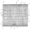
Fig. 1 is a side view of the outer circumferential surface of the instant inventive printing assembly. -
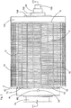
Fig. 2 is a sectional view as indicated inFig. 1 . -
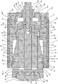
Fig. 3 depicts the assembly ofFig. 1 , the view ofFig. 3 further showing axially received mounting axle components. -
Fig. 4 is a sectional view as indicated inFig. 3 . -
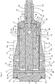
Fig. 5 redepicts the structure shown in the sectional view ofFig. 4 , the view ofFig. 5 omitting radially outer cylinder components of the assembly. -
Fig. 6 is perspective view of a tiered clamping sleeve component of the instant inventive assembly. -
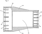
Fig. 7 is a sectional view as indicated inFig. 6 . - Referring now to the drawings, and in particular to Drawing
Fig. 1 , a preferred embodiment of the instant inventive printing assembly includes a cylinder or roll component which is referred to generally byReference Arrow 1. Thecylinder 1 has an outer circumferential surface comprising radially outer aspects ofridges 10 and axial and oppositelyaxial cylinder surfaces axial ends Fig. 2 , the cylinder ends 7 and 8, and axially extendingridges 10 in combination with outer surfaces 6 of the cylinder'sbody 3 advantageously form a plurality of magnet and magnetic polepieces receiving recesses - Multiplicities of
magnets 12, and mild paramagneticsteel pole pieces 14 are preferably fixedly embedded via adhesive bonding within therecesses magnets 12 andpole pieces 14 form with the radially outer surfaces of the ridges 10 a substantially continuous outer circumferential surface for, referring further simultaneously toFig. 4 , secure attachment and mounting of flexible ferro-magnetic printing die 15. - In a preferred embodiment, the poles of the
magnets 12 are axially aligned and themagnets 12 are arranged in relation to each other in an "... NN,SS,NN,SS,NN,SS ..." series order. Eachmagnet 12 of the series preferably abuts apole piece 14 at each of its poles. Such orientation and arrangement of themagnets 12 in relation to thepole pieces 14 advantageously maximizes attractive magnetic die plate holding strength at the cylinder's outer circumferential surface. - Referring simultaneously to
Figs. 1 and2 , the printing assembly preferably further comprises a clamping annulus which is referred to and identified byReference Numerals 20a and 20oa, 20a representing an axial end of such annulus and 20oa representing an oppositely axial end of such annulus. An outer circumferential end or limit of theclamping annulus 20a,20oa is associated withReference Numerals circumferential end clamping annulus 20a is markedly greater than the diameter of the oppositely axial end of the clamping annulus 20oa. Such diameter differential is reflected at a tiered step ortransition 24 between the two annulus portions. In a preferred embodiment, such diameter differential is between 2.54 cm and 5.08 cm (1" and 2"). - Referring to
Fig. 2 , a radially inner periphery or limit of theclamping annulus 20a,20oa is denoted byReference Numeral 28. The enlarged axial end of theclamping annulus 20a,20oa advantageously forms and defines a toroidal guide sleeve receiving space which may advantageously assist in insertions into and receipts of a clamp jaw supporting guide sleeve which is discussed further below. - Referring simultaneously to
Figs. 1 and2 , thecylinder 1 preferably has a hollow bore 5 which is formed and defined by the cylinder's tieredinner wall clamping annulus 20a,20oa, the diameter of the axial end of bore 5 defined byinner wall portion 30 is markedly greater than the corresponding oppositely axial diameter defined byinner wall 34, and a preferably 90° annular step orland 32 forms a transition between such inner wall tiers. Axial and oppositelyaxial compression rings inner wall tiers cylinder 1 as discussed below, thecompression rings midplane 37. Helically threaded mountingplate attachment sockets 40 are preferably presented at the oppositelyaxial end 18 of thecylinder 1. - Referring simultaneously to
Figs. 1 ,2 , and5 , it may be seen that theclamping annulus component 20a,20oa,22,24,26,28 is represented in the drawings. InFig. 5 the cylinder components ofFig. 2 are removed and axle components of the instant inventive assembly are presented. Driveaxle 74 which extends from a printing machine (not shown within views) may provide cantilevering support for and rotational drive to thecylinder 1. Theaxle 74 preferably includes or incorporates an oppositely axialclamp jaw ring 56, such ring preferably having a radially enlarged oppositelyaxial end 54 whoseaxial face 52 is annularly chamfered or beveled. The inside diameter of theclamp jaw ring 56 is preferably closely fitted to the outside diameter of an inwardly stepped oppositely axial end ofaxle 74, and the axial end ofring 56 preferably securely abuts axle step orland 76. In a preferred embodiment,clamp jaw ring 56 is securely held in place againstland 76 by aretainer clip 78. By providingsuch retainer clip 78, and by configuring the oppositely axialclamp jaw ring 56 for function as a removable and attachable component ofaxle 74, the printing assembly allows for axial installations of components over theaxle 74 without interference with the enlargedjaw portion 54 ofring 56. Further structural components of the axle component include atie travel channel 75 and a "T"bar travel channel 80 whose functions are further discussed below. - Referring simultaneously to
Figs. 5-7 , a tiered clamping sleeve component of the printing assembly is referred to generally byReference Arrow 58. The axial end of thetiered clamping sleeve 58 preferably presents an inwardly and annularly chamferedface 72, and the oppositely axial end of such sleeve preferably correspondingly presents an annular inwardly chamferedface 66. The axial and oppositely axial ends of thetiered clamping sleeve 58 preferably respectively present radially arrayedslots wedge clamping sections bore 60 ofsleeve 58 is preferably closely fitted for sliding receipt ofaxle 74, and the oppositely axial end of thebore 60 preferably presents an outward step ortier 59 for guide sleeve receipt and clearance as discussed below. - Referring further simultaneously to
Figs. 5-7 , upon slidable mounting of thetier clamping sleeve 58 over theaxle 70, in the manner depicted inFig. 5 , and upon forceful driving of thesleeve 58 in the oppositely axial direction, chamfered faces 52 and 66 advantageously engage each other to radially outwardly deflectwedge sections 64 within the oppositely axial portion 20oa of the assembly's clamping annulus. In order to effectively exert such oppositely axially directed driving force against thetiered clamping sleeve 58, an annular and outwardly chamferedjaw face 42 is preferably provided, such face preferably being positioned for similarly angled engagements with chamferedaxial face 72 ofsleeve 58. As a result of such matching chamfered engagement offaces faces wedge sections 70 ofsleeve 58 are substantially simultaneously radially outwardly deflected within the clamping annulus'saxial end 20a. - In order to effectively support and guide the oppositely axial driving action of the
axial jaw 42, a ring configuredguide sleeve 44 is preferably fixedly attached to or formed wholly with theaxial jaw 42,such guide sleeve 44 preferably being closely fitted for sliding receipt over theaxle 74 and within the annulus formed bysleeve step 59 andwedge sections 70. The oppositelyaxial end 46 of theguide sleeve 44 preferably terminates short of any interference with or impingement againstsleeve step 59. - Referring further to
Fig. 5 , means for oppositely axially drivingjaw face 42 against thetiered clamping sleeve 58 in the manner described above are preferably provided, such means preferably comprising a jack screw assembly. - Such assembly preferably comprises a
bolt 100 having helical threads at its axial end. Thebolt 100 is preferably rotatably supported at the oppositely axial end of theaxle 74 by means of abearing ring 90 whose axial end is fitted for receiving and bridging over axle end components, and fitted for abutting engagement of ring face 94 against the oppositely axial face ofclamp jaw ring 56. Arotation stopping pin 82 is preferably provided for allowing axial installations and deinstallations of bearingring 90 over the oppositely axial end ofaxle 74 while resisting rotation of that ring with respect to theaxle 74. - The
axial end 96 of thebore 92 which rotatably receivesbolt 100 is preferably enlarged for receipt of a coaxially mounted biasingspring 98 which, in operative engagement withclip 104, axially biases thebolt 100 for easing threaded engagements as discussed below. - Referring further to
Fig. 5 , atie bar 84 which is closely fitted for sliding axial movement within thechannel 75 ofaxle 74 preferably presents an oppositely axially opening helically threadedsocket 88. Upon threaded engagement of thebolt 100 with said socket's threads and upon clockwise and right-handed turning of thebolt 100,tie bar 84 is advantageously pulled in the oppositely axial direction with respect to theaxle 74. A "T"bar 85 preferably extends in the radial direction through aradially extending channel 86 within the axial end of thetie bar 84, and upon such oppositely axial drawing oftie bar 84, "T"bar 85 is simultaneously drawn oppositely axially. - Referring further to
Fig. 5 , the assembly'saxial jaw 42 preferably includes an annularrearward extension 39, such extension preferably forming and defining a "T"bar receiving channel 48. Upon engagement of "T"bar 85 with the "T"bar receiving channel 48, the above described oppositely axial drawing force applied to thetie bar 84 further simultaneously drivesjaw 42 against the axial end of thetiered clamping sleeve 58 for radially outwardly clamping deflections of, referring further simultaneously toFig. 7 wedge clamping sections ring 50 is preferably interposed between theaxle 74 and theaxial extension 39 ofclamp jaw 42. - Referring simultaneously to
Figs. 1 ,2 ,4 , and5 , thecylinder 1 ofFig. 1 is shown inFig. 5 as installed overaxle 74. The above described radially outward clamping deflections of thewedge sections sleeve 58 within the clampingannulus 20a,20oa advantageously drives thosewedge sections - Such radially outward deflections of
wedge sections cylinder 1 at a specifically desired location and orientation with respect toaxle 74, such positioning provides for secure and accurate alignment of a magnetically attached ferro-magnetic printing plate 15. - Referring simultaneously to
Figs. 1 and4 , acylinder end cap 104 is preferably fixedly and removably attached to the oppositely axial end ofcylinder 1 by means of helically threadedbolts 41 which extend throughbolt receiving apertures 103 withinend cap 104, and which threadedly engage helically threadedsockets 40. For purposes of close fitting of theend cap 104, and for sealing the assembly against intrusions of dirt and debris, a closely fittedspacer ring 106 havingflange 108 andretainer clip 107 is interposed betweenend cap 104 and bearingmember 90.
Claims (7)
- A printing assembly comprising:(a) a clamping annulus having a tiered circumferential end (22, 26), an axial end (20a) and an oppositely axial end (20oa), the clamping annulus's axial and oppositely axial ends having outside diameters, the axial end's outside diameter having with respect to said oppositely axial end outside diameter an excess dimension defining a guide sleeve receiving space within the clamping annulus;(b) a cylinder (2) having axial (16) and oppositely axial (18) ends, having a circumferential outer surface (6), and having a tiered inner wall (30, 34), the tiered inner wall having axial and oppositely axial ends, the tiered inner wall's axial end overlying the clamping annulus's axial end, and the tiered inner wall's oppositely axial end overlying the clamping annulus's oppositely axial end;(c) an end cap (104) attached to the oppositely axial end (18) of the cylinder (1) with end cap mounting means (40, 41) fixedly attached to or formed wholly with the cylinder's oppositely axial end and overlying the clamping annulus's axial end;(d) a plurality of magnet receiving recesses (2, 4) each recess among the plurality of magnet receiving recesses extending radially into the cylinder, and each recess among the plurality of magnet receiving recesses opening radially outward from the cylinder's circumferential outer surface; and(e) a multiplicity of permanent magnets (12), each magnet among the multiplicity of permanent magnets being embedded within one of the recesses among the plurality of magnet receiving recesses.
- The printing assembly of Claim 1 wherein the clamping annulus's axial end opens axially for, upon an oppositely axial extension of a guide sleeve (44), receiving the guide sleeve within the clamping annuluses' guide sleeve receiving space.
- The printing assembly of Claim 2 wherein the clamping annulus comprises a radial transition dividing the clamping annulus's axial and oppositely axial ends.
- The printing assembly of Claim 3 further comprising axial and oppositely axial compression rings (36, 38), said rings being fixedly attached to the cylinder's tiered inner wall.
- The printing assembly of Claim 4 wherein the cylinder has an axial length and a midplane bisecting the axial length, wherein the axial compression ring (36) is positioned axially from the midplane, and wherein the oppositely axial compression ring (38) is positioned oppositely axially from the midplane.
- The printing assembly of Claim 5 wherein the axial compression ring (36) is further axially positioned at the cylinder's axial end.
- The printing assembly of any preceding Claim wherein the end cap mounting means comprise a plurality of mounting sockets (40) or a plurality of mounting lugs.
Priority Applications (1)
| Application Number | Priority Date | Filing Date | Title |
|---|---|---|---|
| PL14826777T PL3022057T3 (en) | 2013-07-18 | 2014-07-18 | Printing assembly |
Applications Claiming Priority (2)
| Application Number | Priority Date | Filing Date | Title |
|---|---|---|---|
| US13/945,726 US9162439B2 (en) | 2013-07-18 | 2013-07-18 | Printing assembly |
| PCT/US2014/047184 WO2015010013A2 (en) | 2013-07-18 | 2014-07-18 | Printing assembly |
Publications (3)
| Publication Number | Publication Date |
|---|---|
| EP3022057A2 EP3022057A2 (en) | 2016-05-25 |
| EP3022057A4 EP3022057A4 (en) | 2017-04-26 |
| EP3022057B1 true EP3022057B1 (en) | 2020-04-15 |
Family
ID=50146866
Family Applications (1)
| Application Number | Title | Priority Date | Filing Date |
|---|---|---|---|
| EP14826777.6A Active EP3022057B1 (en) | 2013-07-18 | 2014-07-18 | Printing assembly |
Country Status (4)
| Country | Link |
|---|---|
| US (2) | US9162439B2 (en) |
| EP (1) | EP3022057B1 (en) |
| PL (1) | PL3022057T3 (en) |
| WO (1) | WO2015010013A2 (en) |
Families Citing this family (2)
| Publication number | Priority date | Publication date | Assignee | Title |
|---|---|---|---|---|
| JP6243576B2 (en) * | 2015-04-21 | 2017-12-06 | 株式会社シンク・ラボラトリー | Functional cylinder body and manufacturing method thereof |
| GB201915458D0 (en) | 2019-10-24 | 2019-12-11 | Sandon Global Engraving Tech Limited | Lightweight interchangeable magnetic sleeve and method of manufacture thereof |
Family Cites Families (13)
| Publication number | Priority date | Publication date | Assignee | Title |
|---|---|---|---|---|
| US1674635A (en) * | 1926-02-08 | 1928-06-26 | Paper & Textile Machinery Co | Expansion mandrel |
| US1958299A (en) * | 1930-10-15 | 1934-05-08 | Standard Process Corp | Intaglio printing methods and apparatus |
| US2987994A (en) * | 1958-08-18 | 1961-06-13 | Thomas K Allison | Mandrel and cylinder for gravure printing |
| US3590452A (en) * | 1969-01-09 | 1971-07-06 | Dayco Corp | Roller applicator device |
| US3739722A (en) * | 1971-08-13 | 1973-06-19 | Gross Instr Co | Print roll and mounting means |
| CH549474A (en) * | 1973-01-29 | 1974-05-31 | Buser Ag Maschf Fritz | DEVICE ON ROTARY FILM PRINTING MACHINE FOR DETACHABLE ATTACHMENT OF A ROUND STENCIL. |
| US3919937A (en) * | 1974-03-15 | 1975-11-18 | Donnelley & Sons Co | Magnetic cylinder for printing presses |
| NL8003073A (en) | 1980-05-28 | 1982-01-04 | Stork Screens Bv | PRESSURE CYLINDER PROVIDED WITH AN EXTERNAL COATING, METHOD AND APPARATUS FOR COATING A CYLINDER SURFACE. |
| US4503769A (en) * | 1982-06-21 | 1985-03-12 | Armotek Industries, Inc. | Metal coated thin wall plastic printing cylinder for rotogravure printing |
| US6363850B1 (en) * | 1999-11-22 | 2002-04-02 | Mceachern David A. | Mounting printing plate cylinder having tapered bore to untapered rotatable drive shaft |
| DE50111987D1 (en) * | 2000-05-17 | 2007-03-22 | Eastman Kodak Co | Replaceable cylinder elements on electrographic printing units |
| DE10304117A1 (en) * | 2003-01-31 | 2004-08-05 | Giesecke & Devrient Gmbh | Clamping cylinder for clamping cylindrical stamping dies for stamping rollers |
| EP1555123A1 (en) * | 2004-01-17 | 2005-07-20 | Wilfried Jeurink | Printing press |
-
2013
- 2013-07-18 US US13/945,726 patent/US9162439B2/en active Active
-
2014
- 2014-07-18 WO PCT/US2014/047184 patent/WO2015010013A2/en not_active Ceased
- 2014-07-18 PL PL14826777T patent/PL3022057T3/en unknown
- 2014-07-18 EP EP14826777.6A patent/EP3022057B1/en active Active
-
2015
- 2015-09-17 US US14/857,093 patent/US9308717B2/en active Active
Non-Patent Citations (1)
| Title |
|---|
| None * |
Also Published As
| Publication number | Publication date |
|---|---|
| EP3022057A2 (en) | 2016-05-25 |
| WO2015010013A2 (en) | 2015-01-22 |
| US9308717B2 (en) | 2016-04-12 |
| EP3022057A4 (en) | 2017-04-26 |
| PL3022057T3 (en) | 2020-11-02 |
| US20160001547A1 (en) | 2016-01-07 |
| US9162439B2 (en) | 2015-10-20 |
| US20140053747A1 (en) | 2014-02-27 |
| WO2015010013A3 (en) | 2015-06-04 |
Similar Documents
| Publication | Publication Date | Title |
|---|---|---|
| EP2399673B1 (en) | Roller for high pressure roller grinder, roller grinder and method for assembling a roller for a roller grinder | |
| EP3678820B1 (en) | Systems and methods for removing bearing cups | |
| US9162439B2 (en) | Printing assembly | |
| US8915185B2 (en) | Assembly for axially aligning a print die | |
| CN103964238B (en) | Slitter machine unrolling fixing device and high-speed slitter machine | |
| CN205168036U (en) | Commercial car front axle wheel anti -theft device | |
| CN203114941U (en) | Clutch and center sleeve thereof | |
| US8997322B1 (en) | Compact and portable hydraulic extracting and installing apparatus and associated method | |
| CN205799367U (en) | A kind of pulley extractor and wheel disc thereof | |
| CN203820111U (en) | Unreeling and fixing device for splitting machine and high-speed splitting machine | |
| CN214945903U (en) | Brake of integrated multi-point braking heavy-load elevator tractor | |
| CN201180072Y (en) | External rotor type permanent magnetism synchronous gearless machine | |
| CN115263932A (en) | Tapered roller bearing for automobile hub | |
| CN209250441U (en) | A kind of hydraulic horizontal magneto attaching/detaching apparatus | |
| CN101387318A (en) | Machine element for a shaft-to-hub connection and production method for a shaft-to-hub connection | |
| CN210616372U (en) | A multifunctional simple disassembly device | |
| CN210770125U (en) | Belt pulley | |
| CN221974235U (en) | Connection assembly between reducer hollow shaft and driven shaft | |
| CN220770016U (en) | High-strength light brake cam shaft | |
| CN206344317U (en) | A kind of retractable cable wheel mechanism for silico briquette single line shear | |
| CN218743935U (en) | High-efficient complex function's roll for rolling press | |
| CN223431216U (en) | Pulley removal device | |
| CN210431169U (en) | Clamping assembly tool suitable for disassembly and assembly without disassembly of motor bearing | |
| CN210307620U (en) | Bearing disassembling tool | |
| TW201420416A (en) | Bike hub disc brake structure allowing axial double-sided clamping |
Legal Events
| Date | Code | Title | Description |
|---|---|---|---|
| PUAI | Public reference made under article 153(3) epc to a published international application that has entered the european phase |
Free format text: ORIGINAL CODE: 0009012 |
|
| 17P | Request for examination filed |
Effective date: 20160114 |
|
| AK | Designated contracting states |
Kind code of ref document: A2 Designated state(s): AL AT BE BG CH CY CZ DE DK EE ES FI FR GB GR HR HU IE IS IT LI LT LU LV MC MK MT NL NO PL PT RO RS SE SI SK SM TR |
|
| AX | Request for extension of the european patent |
Extension state: BA ME |
|
| DAX | Request for extension of the european patent (deleted) | ||
| A4 | Supplementary search report drawn up and despatched |
Effective date: 20170324 |
|
| RIC1 | Information provided on ipc code assigned before grant |
Ipc: B41F 27/02 20060101AFI20170320BHEP |
|
| REG | Reference to a national code |
Ref country code: DE Ref legal event code: R079 Ref document number: 602014063879 Country of ref document: DE Free format text: PREVIOUS MAIN CLASS: B41F0013200000 Ipc: B41F0027020000 |
|
| GRAP | Despatch of communication of intention to grant a patent |
Free format text: ORIGINAL CODE: EPIDOSNIGR1 |
|
| STAA | Information on the status of an ep patent application or granted ep patent |
Free format text: STATUS: GRANT OF PATENT IS INTENDED |
|
| RIC1 | Information provided on ipc code assigned before grant |
Ipc: B41F 27/02 20060101AFI20190502BHEP |
|
| INTG | Intention to grant announced |
Effective date: 20190605 |
|
| GRAJ | Information related to disapproval of communication of intention to grant by the applicant or resumption of examination proceedings by the epo deleted |
Free format text: ORIGINAL CODE: EPIDOSDIGR1 |
|
| STAA | Information on the status of an ep patent application or granted ep patent |
Free format text: STATUS: REQUEST FOR EXAMINATION WAS MADE |
|
| GRAP | Despatch of communication of intention to grant a patent |
Free format text: ORIGINAL CODE: EPIDOSNIGR1 |
|
| STAA | Information on the status of an ep patent application or granted ep patent |
Free format text: STATUS: GRANT OF PATENT IS INTENDED |
|
| INTC | Intention to grant announced (deleted) | ||
| INTG | Intention to grant announced |
Effective date: 20191030 |
|
| GRAS | Grant fee paid |
Free format text: ORIGINAL CODE: EPIDOSNIGR3 |
|
| GRAA | (expected) grant |
Free format text: ORIGINAL CODE: 0009210 |
|
| STAA | Information on the status of an ep patent application or granted ep patent |
Free format text: STATUS: THE PATENT HAS BEEN GRANTED |
|
| AK | Designated contracting states |
Kind code of ref document: B1 Designated state(s): AL AT BE BG CH CY CZ DE DK EE ES FI FR GB GR HR HU IE IS IT LI LT LU LV MC MK MT NL NO PL PT RO RS SE SI SK SM TR |
|
| REG | Reference to a national code |
Ref country code: CH Ref legal event code: EP |
|
| REG | Reference to a national code |
Ref country code: DE Ref legal event code: R096 Ref document number: 602014063879 Country of ref document: DE |
|
| REG | Reference to a national code |
Ref country code: IE Ref legal event code: FG4D |
|
| REG | Reference to a national code |
Ref country code: AT Ref legal event code: REF Ref document number: 1256791 Country of ref document: AT Kind code of ref document: T Effective date: 20200515 |
|
| REG | Reference to a national code |
Ref country code: NL Ref legal event code: MP Effective date: 20200415 |
|
| REG | Reference to a national code |
Ref country code: LT Ref legal event code: MG4D |
|
| PG25 | Lapsed in a contracting state [announced via postgrant information from national office to epo] |
Ref country code: SE Free format text: LAPSE BECAUSE OF FAILURE TO SUBMIT A TRANSLATION OF THE DESCRIPTION OR TO PAY THE FEE WITHIN THE PRESCRIBED TIME-LIMIT Effective date: 20200415 Ref country code: IS Free format text: LAPSE BECAUSE OF FAILURE TO SUBMIT A TRANSLATION OF THE DESCRIPTION OR TO PAY THE FEE WITHIN THE PRESCRIBED TIME-LIMIT Effective date: 20200815 Ref country code: NO Free format text: LAPSE BECAUSE OF FAILURE TO SUBMIT A TRANSLATION OF THE DESCRIPTION OR TO PAY THE FEE WITHIN THE PRESCRIBED TIME-LIMIT Effective date: 20200715 Ref country code: FI Free format text: LAPSE BECAUSE OF FAILURE TO SUBMIT A TRANSLATION OF THE DESCRIPTION OR TO PAY THE FEE WITHIN THE PRESCRIBED TIME-LIMIT Effective date: 20200415 Ref country code: GR Free format text: LAPSE BECAUSE OF FAILURE TO SUBMIT A TRANSLATION OF THE DESCRIPTION OR TO PAY THE FEE WITHIN THE PRESCRIBED TIME-LIMIT Effective date: 20200716 Ref country code: LT Free format text: LAPSE BECAUSE OF FAILURE TO SUBMIT A TRANSLATION OF THE DESCRIPTION OR TO PAY THE FEE WITHIN THE PRESCRIBED TIME-LIMIT Effective date: 20200415 Ref country code: NL Free format text: LAPSE BECAUSE OF FAILURE TO SUBMIT A TRANSLATION OF THE DESCRIPTION OR TO PAY THE FEE WITHIN THE PRESCRIBED TIME-LIMIT Effective date: 20200415 Ref country code: PT Free format text: LAPSE BECAUSE OF FAILURE TO SUBMIT A TRANSLATION OF THE DESCRIPTION OR TO PAY THE FEE WITHIN THE PRESCRIBED TIME-LIMIT Effective date: 20200817 |
|
| REG | Reference to a national code |
Ref country code: AT Ref legal event code: MK05 Ref document number: 1256791 Country of ref document: AT Kind code of ref document: T Effective date: 20200415 |
|
| PG25 | Lapsed in a contracting state [announced via postgrant information from national office to epo] |
Ref country code: HR Free format text: LAPSE BECAUSE OF FAILURE TO SUBMIT A TRANSLATION OF THE DESCRIPTION OR TO PAY THE FEE WITHIN THE PRESCRIBED TIME-LIMIT Effective date: 20200415 Ref country code: LV Free format text: LAPSE BECAUSE OF FAILURE TO SUBMIT A TRANSLATION OF THE DESCRIPTION OR TO PAY THE FEE WITHIN THE PRESCRIBED TIME-LIMIT Effective date: 20200415 Ref country code: RS Free format text: LAPSE BECAUSE OF FAILURE TO SUBMIT A TRANSLATION OF THE DESCRIPTION OR TO PAY THE FEE WITHIN THE PRESCRIBED TIME-LIMIT Effective date: 20200415 Ref country code: BG Free format text: LAPSE BECAUSE OF FAILURE TO SUBMIT A TRANSLATION OF THE DESCRIPTION OR TO PAY THE FEE WITHIN THE PRESCRIBED TIME-LIMIT Effective date: 20200715 |
|
| PG25 | Lapsed in a contracting state [announced via postgrant information from national office to epo] |
Ref country code: AL Free format text: LAPSE BECAUSE OF FAILURE TO SUBMIT A TRANSLATION OF THE DESCRIPTION OR TO PAY THE FEE WITHIN THE PRESCRIBED TIME-LIMIT Effective date: 20200415 |
|
| REG | Reference to a national code |
Ref country code: DE Ref legal event code: R097 Ref document number: 602014063879 Country of ref document: DE |
|
| PG25 | Lapsed in a contracting state [announced via postgrant information from national office to epo] |
Ref country code: IT Free format text: LAPSE BECAUSE OF FAILURE TO SUBMIT A TRANSLATION OF THE DESCRIPTION OR TO PAY THE FEE WITHIN THE PRESCRIBED TIME-LIMIT Effective date: 20200415 Ref country code: SM Free format text: LAPSE BECAUSE OF FAILURE TO SUBMIT A TRANSLATION OF THE DESCRIPTION OR TO PAY THE FEE WITHIN THE PRESCRIBED TIME-LIMIT Effective date: 20200415 Ref country code: ES Free format text: LAPSE BECAUSE OF FAILURE TO SUBMIT A TRANSLATION OF THE DESCRIPTION OR TO PAY THE FEE WITHIN THE PRESCRIBED TIME-LIMIT Effective date: 20200415 Ref country code: AT Free format text: LAPSE BECAUSE OF FAILURE TO SUBMIT A TRANSLATION OF THE DESCRIPTION OR TO PAY THE FEE WITHIN THE PRESCRIBED TIME-LIMIT Effective date: 20200415 Ref country code: DK Free format text: LAPSE BECAUSE OF FAILURE TO SUBMIT A TRANSLATION OF THE DESCRIPTION OR TO PAY THE FEE WITHIN THE PRESCRIBED TIME-LIMIT Effective date: 20200415 Ref country code: CZ Free format text: LAPSE BECAUSE OF FAILURE TO SUBMIT A TRANSLATION OF THE DESCRIPTION OR TO PAY THE FEE WITHIN THE PRESCRIBED TIME-LIMIT Effective date: 20200415 Ref country code: EE Free format text: LAPSE BECAUSE OF FAILURE TO SUBMIT A TRANSLATION OF THE DESCRIPTION OR TO PAY THE FEE WITHIN THE PRESCRIBED TIME-LIMIT Effective date: 20200415 Ref country code: RO Free format text: LAPSE BECAUSE OF FAILURE TO SUBMIT A TRANSLATION OF THE DESCRIPTION OR TO PAY THE FEE WITHIN THE PRESCRIBED TIME-LIMIT Effective date: 20200415 |
|
| PLBE | No opposition filed within time limit |
Free format text: ORIGINAL CODE: 0009261 |
|
| STAA | Information on the status of an ep patent application or granted ep patent |
Free format text: STATUS: NO OPPOSITION FILED WITHIN TIME LIMIT |
|
| PG25 | Lapsed in a contracting state [announced via postgrant information from national office to epo] |
Ref country code: SK Free format text: LAPSE BECAUSE OF FAILURE TO SUBMIT A TRANSLATION OF THE DESCRIPTION OR TO PAY THE FEE WITHIN THE PRESCRIBED TIME-LIMIT Effective date: 20200415 Ref country code: MC Free format text: LAPSE BECAUSE OF FAILURE TO SUBMIT A TRANSLATION OF THE DESCRIPTION OR TO PAY THE FEE WITHIN THE PRESCRIBED TIME-LIMIT Effective date: 20200415 |
|
| REG | Reference to a national code |
Ref country code: CH Ref legal event code: PL |
|
| 26N | No opposition filed |
Effective date: 20210118 |
|
| REG | Reference to a national code |
Ref country code: BE Ref legal event code: MM Effective date: 20200731 |
|
| PG25 | Lapsed in a contracting state [announced via postgrant information from national office to epo] |
Ref country code: LU Free format text: LAPSE BECAUSE OF NON-PAYMENT OF DUE FEES Effective date: 20200718 Ref country code: LI Free format text: LAPSE BECAUSE OF NON-PAYMENT OF DUE FEES Effective date: 20200731 Ref country code: CH Free format text: LAPSE BECAUSE OF NON-PAYMENT OF DUE FEES Effective date: 20200731 |
|
| PG25 | Lapsed in a contracting state [announced via postgrant information from national office to epo] |
Ref country code: BE Free format text: LAPSE BECAUSE OF NON-PAYMENT OF DUE FEES Effective date: 20200731 Ref country code: SI Free format text: LAPSE BECAUSE OF FAILURE TO SUBMIT A TRANSLATION OF THE DESCRIPTION OR TO PAY THE FEE WITHIN THE PRESCRIBED TIME-LIMIT Effective date: 20200415 |
|
| PG25 | Lapsed in a contracting state [announced via postgrant information from national office to epo] |
Ref country code: IE Free format text: LAPSE BECAUSE OF NON-PAYMENT OF DUE FEES Effective date: 20200718 |
|
| PG25 | Lapsed in a contracting state [announced via postgrant information from national office to epo] |
Ref country code: TR Free format text: LAPSE BECAUSE OF FAILURE TO SUBMIT A TRANSLATION OF THE DESCRIPTION OR TO PAY THE FEE WITHIN THE PRESCRIBED TIME-LIMIT Effective date: 20200415 Ref country code: MT Free format text: LAPSE BECAUSE OF FAILURE TO SUBMIT A TRANSLATION OF THE DESCRIPTION OR TO PAY THE FEE WITHIN THE PRESCRIBED TIME-LIMIT Effective date: 20200415 Ref country code: CY Free format text: LAPSE BECAUSE OF FAILURE TO SUBMIT A TRANSLATION OF THE DESCRIPTION OR TO PAY THE FEE WITHIN THE PRESCRIBED TIME-LIMIT Effective date: 20200415 |
|
| PG25 | Lapsed in a contracting state [announced via postgrant information from national office to epo] |
Ref country code: MK Free format text: LAPSE BECAUSE OF FAILURE TO SUBMIT A TRANSLATION OF THE DESCRIPTION OR TO PAY THE FEE WITHIN THE PRESCRIBED TIME-LIMIT Effective date: 20200415 |
|
| PGFP | Annual fee paid to national office [announced via postgrant information from national office to epo] |
Ref country code: GB Payment date: 20240625 Year of fee payment: 11 |
|
| PGFP | Annual fee paid to national office [announced via postgrant information from national office to epo] |
Ref country code: DE Payment date: 20240719 Year of fee payment: 11 |
|
| PGFP | Annual fee paid to national office [announced via postgrant information from national office to epo] |
Ref country code: FR Payment date: 20240731 Year of fee payment: 11 |
|
| PGFP | Annual fee paid to national office [announced via postgrant information from national office to epo] |
Ref country code: PL Payment date: 20240705 Year of fee payment: 11 |
|
| REG | Reference to a national code |
Ref country code: DE Ref legal event code: R119 Ref document number: 602014063879 Country of ref document: DE |
|
| GBPC | Gb: european patent ceased through non-payment of renewal fee |
Effective date: 20250718 |
|
| PG25 | Lapsed in a contracting state [announced via postgrant information from national office to epo] |
Ref country code: GB Free format text: LAPSE BECAUSE OF NON-PAYMENT OF DUE FEES Effective date: 20250718 |
|
| PG25 | Lapsed in a contracting state [announced via postgrant information from national office to epo] |
Ref country code: DE Free format text: LAPSE BECAUSE OF NON-PAYMENT OF DUE FEES Effective date: 20260203 |
|
| PG25 | Lapsed in a contracting state [announced via postgrant information from national office to epo] |
Ref country code: FR Free format text: LAPSE BECAUSE OF NON-PAYMENT OF DUE FEES Effective date: 20250731 |
|
| PG25 | Lapsed in a contracting state [announced via postgrant information from national office to epo] |
Ref country code: PL Free format text: LAPSE BECAUSE OF NON-PAYMENT OF DUE FEES Effective date: 20250718 |