EP3021985B1 - Pulvérisateur - Google Patents
Pulvérisateur Download PDFInfo
- Publication number
- EP3021985B1 EP3021985B1 EP14752435.9A EP14752435A EP3021985B1 EP 3021985 B1 EP3021985 B1 EP 3021985B1 EP 14752435 A EP14752435 A EP 14752435A EP 3021985 B1 EP3021985 B1 EP 3021985B1
- Authority
- EP
- European Patent Office
- Prior art keywords
- sprayer
- housing
- fluid
- bridge
- outlet
- Prior art date
- Legal status (The legal status is an assumption and is not a legal conclusion. Google has not performed a legal analysis and makes no representation as to the accuracy of the status listed.)
- Not-in-force
Links
Images







Classifications
-
- B—PERFORMING OPERATIONS; TRANSPORTING
- B05—SPRAYING OR ATOMISING IN GENERAL; APPLYING FLUENT MATERIALS TO SURFACES, IN GENERAL
- B05B—SPRAYING APPARATUS; ATOMISING APPARATUS; NOZZLES
- B05B1/00—Nozzles, spray heads or other outlets, with or without auxiliary devices such as valves, heating means
- B05B1/30—Nozzles, spray heads or other outlets, with or without auxiliary devices such as valves, heating means designed to control volume of flow, e.g. with adjustable passages
- B05B1/3033—Nozzles, spray heads or other outlets, with or without auxiliary devices such as valves, heating means designed to control volume of flow, e.g. with adjustable passages the control being effected by relative coaxial longitudinal movement of the controlling element and the spray head
- B05B1/308—Nozzles, spray heads or other outlets, with or without auxiliary devices such as valves, heating means designed to control volume of flow, e.g. with adjustable passages the control being effected by relative coaxial longitudinal movement of the controlling element and the spray head the controlling element comprising both a lift valve and a deflector separated from the lift valve
-
- B—PERFORMING OPERATIONS; TRANSPORTING
- B05—SPRAYING OR ATOMISING IN GENERAL; APPLYING FLUENT MATERIALS TO SURFACES, IN GENERAL
- B05B—SPRAYING APPARATUS; ATOMISING APPARATUS; NOZZLES
- B05B3/00—Spraying or sprinkling apparatus with moving outlet elements or moving deflecting elements
- B05B3/02—Spraying or sprinkling apparatus with moving outlet elements or moving deflecting elements with rotating elements
- B05B3/04—Spraying or sprinkling apparatus with moving outlet elements or moving deflecting elements with rotating elements driven by the liquid or other fluent material discharged, e.g. the liquid actuating a motor before passing to the outlet
-
- B—PERFORMING OPERATIONS; TRANSPORTING
- B05—SPRAYING OR ATOMISING IN GENERAL; APPLYING FLUENT MATERIALS TO SURFACES, IN GENERAL
- B05B—SPRAYING APPARATUS; ATOMISING APPARATUS; NOZZLES
- B05B1/00—Nozzles, spray heads or other outlets, with or without auxiliary devices such as valves, heating means
- B05B1/26—Nozzles, spray heads or other outlets, with or without auxiliary devices such as valves, heating means with means for mechanically breaking-up or deflecting the jet after discharge, e.g. with fixed deflectors; Breaking-up the discharged liquid or other fluent material by impinging jets
- B05B1/262—Nozzles, spray heads or other outlets, with or without auxiliary devices such as valves, heating means with means for mechanically breaking-up or deflecting the jet after discharge, e.g. with fixed deflectors; Breaking-up the discharged liquid or other fluent material by impinging jets with fixed deflectors
- B05B1/267—Nozzles, spray heads or other outlets, with or without auxiliary devices such as valves, heating means with means for mechanically breaking-up or deflecting the jet after discharge, e.g. with fixed deflectors; Breaking-up the discharged liquid or other fluent material by impinging jets with fixed deflectors the liquid or other fluent material being deflected in determined directions
-
- B—PERFORMING OPERATIONS; TRANSPORTING
- B05—SPRAYING OR ATOMISING IN GENERAL; APPLYING FLUENT MATERIALS TO SURFACES, IN GENERAL
- B05B—SPRAYING APPARATUS; ATOMISING APPARATUS; NOZZLES
- B05B1/00—Nozzles, spray heads or other outlets, with or without auxiliary devices such as valves, heating means
- B05B1/30—Nozzles, spray heads or other outlets, with or without auxiliary devices such as valves, heating means designed to control volume of flow, e.g. with adjustable passages
- B05B1/3006—Nozzles, spray heads or other outlets, with or without auxiliary devices such as valves, heating means designed to control volume of flow, e.g. with adjustable passages the controlling element being actuated by the pressure of the fluid to be sprayed
-
- B—PERFORMING OPERATIONS; TRANSPORTING
- B05—SPRAYING OR ATOMISING IN GENERAL; APPLYING FLUENT MATERIALS TO SURFACES, IN GENERAL
- B05B—SPRAYING APPARATUS; ATOMISING APPARATUS; NOZZLES
- B05B1/00—Nozzles, spray heads or other outlets, with or without auxiliary devices such as valves, heating means
- B05B1/30—Nozzles, spray heads or other outlets, with or without auxiliary devices such as valves, heating means designed to control volume of flow, e.g. with adjustable passages
- B05B1/32—Nozzles, spray heads or other outlets, with or without auxiliary devices such as valves, heating means designed to control volume of flow, e.g. with adjustable passages in which a valve member forms part of the outlet opening
- B05B1/323—Nozzles, spray heads or other outlets, with or without auxiliary devices such as valves, heating means designed to control volume of flow, e.g. with adjustable passages in which a valve member forms part of the outlet opening the valve member being actuated by the pressure of the fluid to be sprayed
-
- B—PERFORMING OPERATIONS; TRANSPORTING
- B05—SPRAYING OR ATOMISING IN GENERAL; APPLYING FLUENT MATERIALS TO SURFACES, IN GENERAL
- B05B—SPRAYING APPARATUS; ATOMISING APPARATUS; NOZZLES
- B05B15/00—Details of spraying plant or spraying apparatus not otherwise provided for; Accessories
- B05B15/70—Arrangements for moving spray heads automatically to or from the working position
-
- B—PERFORMING OPERATIONS; TRANSPORTING
- B05—SPRAYING OR ATOMISING IN GENERAL; APPLYING FLUENT MATERIALS TO SURFACES, IN GENERAL
- B05B—SPRAYING APPARATUS; ATOMISING APPARATUS; NOZZLES
- B05B3/00—Spraying or sprinkling apparatus with moving outlet elements or moving deflecting elements
- B05B3/02—Spraying or sprinkling apparatus with moving outlet elements or moving deflecting elements with rotating elements
- B05B3/04—Spraying or sprinkling apparatus with moving outlet elements or moving deflecting elements with rotating elements driven by the liquid or other fluent material discharged, e.g. the liquid actuating a motor before passing to the outlet
- B05B3/0417—Spraying or sprinkling apparatus with moving outlet elements or moving deflecting elements with rotating elements driven by the liquid or other fluent material discharged, e.g. the liquid actuating a motor before passing to the outlet comprising a liquid driven rotor, e.g. a turbine
- B05B3/0425—Spraying or sprinkling apparatus with moving outlet elements or moving deflecting elements with rotating elements driven by the liquid or other fluent material discharged, e.g. the liquid actuating a motor before passing to the outlet comprising a liquid driven rotor, e.g. a turbine actuated downstream of the outlet elements
- B05B3/0426—Spraying or sprinkling apparatus with moving outlet elements or moving deflecting elements with rotating elements driven by the liquid or other fluent material discharged, e.g. the liquid actuating a motor before passing to the outlet comprising a liquid driven rotor, e.g. a turbine actuated downstream of the outlet elements the liquid driven rotor being a deflecting rotating element
Definitions
- a micro-sprayer in which a jet of irrigation fluid, provided through an inlet of the sprayer, is emitted from an outlet thereof towards a dispersion element of a predetermined geometric shape configured for dispersing the directional jet into different directions, thereby providing the required irrigation fluid to the areas to be irrigated.
- the housing can be constituted by an assembly of two or more components.
- the fluid outlet remains fixedly spaced from the fluid inlet.
- the sprayer can comprise a biasing arrangement configured for constantly urging the bridge into the closed position.
- a biasing arrangement configured for constantly urging the bridge into the closed position.
- One advantage of such an arrangement lies in the ability to position the sprayer at any orientation, regardless of gravitational forces.
- a biasing arrangement can be a biasing spring.
- the bridge can be mounted over the housing by a snap-type arrangement, wherein said arrangement constitutes the top and bottom limiter.
- the bridge can comprise a sleeve configured for being mounted over the housing, said sleeve comprising at least one longitudinal recess configured for receiving therein a projection of the housing.
- At least one of the top and bottom ends can be formed with a nook configured for receiving therein a wedge of the projection of the housing, configured for reducing the bridge's ability to perform a tilting motion about the longitudinal axis.
- the nozzle can be formed with a shaped opening through which irrigation fluid is configured for being discharged.
- the nozzle can comprise several segments between its inlet and outlet so that the diameter of the nozzle is gradually reduced towards the outlet, increasing pressure within the nozzle.
- the housing further comprise two protrusions C configured for reducing the radial degree of freedom of the bridge over the housing, at least when in the open position thereof.
- the protrusions C bridge the gap formed between the bridge 10 and the housing 30.
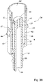
- annular basin B about the nozzle 39, configured for accumulating therein of clogging material (e.g. dirt, mud etc.).
- clogging material e.g. dirt, mud etc.
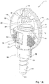
- the bridge 10 comprises a hollow mounting portion 12 configured for receiving therein the sprayer housing 32.
- the mounting portion 12 is formed with two diametrically opposed windows 13 configured for slidingly receiving therein the snap-type latches 44 of the engagement arrangement 40 and two diametrically opposed slots 17 configured for receiving therein the guides 46.
- each of the arms 14 is formed with two sloping surfaces 16 forming a dividing ridge 16 facing the central axis of the sprayer 1.
- the dividing ridge 16 serves to prevent obstruction of the fluid dispersed by the crown 20.
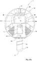
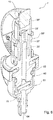
- the sprayer 1 In the position shown in Fig. 4A , the sprayer 1 is in its closed position, the mounting portion 12 of the bridge 10 being received over a bottom portion of the housing body 32 so that the dispersion element 20 rests on the rim of the protecting sleeve 36', thereby sealing it. It is also noted that in the above position, the top end 13b of the window 13 is proximal to the latch 44.
- Fig. 4B in operation, fluid passed into the inlet 34 and emitted from the nozzle 37 as a fluid jet is emitted from the outlet 36 at sufficient pressure as to elevate the crown 20 over the rim of the sleeve 36'. Under such pressure, the entire bridge 10 is displaced upwards so that there is formed a gap g between the crown 20 and the sleeve 36'.
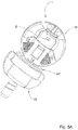
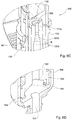
- Figs. 5A and 5B another example of a sprayer is shown, generally designated 1'.
- the sprayer 1' comprises a similar bridge 10, but a modified housing 30' which is configured for articulation to an additional member 50 and comprising a flow-rate regulator 60.
- the bottom portion 162 of element 160 which is configured for holding the diaphragm in place.
- the bottom portion 162 comprises legs 164 circumferentially spaced about the central axis of the sprayer and configured for retaining therein the diaphragm.
Landscapes
- Catching Or Destruction (AREA)
- Special Spraying Apparatus (AREA)
- Nozzles (AREA)
Claims (18)
- Pulvérisateur (1) comprenant :un boîtier (30) présentant une entrée de fluide (34) configurée pour être statiquement couplée à une source de fluide pour recevoir du fluide de celle-ci et une sortie de fluide (36) configurée pour l'évacuation dudit fluide, la distance entre ladite entrée de fluide (34) et ladite sortie de fluide (36, 36') étant fixée ; etun pont (10) monté par-dessus le boîtier (30) et comprenant un élément de dispersion (20) configuré pour la dispersion de fluide évacué de la sortie de fluide (36, 36') du boîtier (30) ;caractérisé en ce que le pont (10) est configuré pour le déplacement par-dessus le boîtier (30) au moins entre une position fermée dans laquelle l'élément de dispersion (20) vient en contact avec la sortie de fluide (36, 36') pour ainsi la sceller, et une position ouverte dans laquelle l'élément de dispersion (20) est espacé de la sortie de fluide (36, 36') par une fente, permettant la dispersion du fluide.
- Pulvérisateur (1) selon la revendication 1, dans lequel le boîtier (30) forme un corps unitaire dans lequel la sortie de fluide (36, 36') est stationnaire par rapport à l'entrée de fluide (34) pendant le fonctionnement et dans lequel l'entrée de fluide (34) et la sortie de fluide (36, 36') sont opposées l'une à l'autre.
- Pulvérisateur (1) selon l'une quelconque des revendications 1 à 2, dans lequel le pont (10) est constamment poussé dans la position fermée et le déplacement du pont (10) de la position fermée à la position ouverte est facilité par la pression de fluide émis par la sortie de fluide (36, 36').
- Pulvérisateur (1) selon la revendication 3, dans lequel le pulvériseur (1) comprend un ressort d'inclinaison configuré pour pousser constamment le pont (10) dans la position fermée.
- Pulvérisateur (1) selon l'une quelconque des revendications 1 à 4, dans lequel le déplacement du pont (10) par-dessus le boîtier (30) est facilité par des guidages (46) formés dans le boîtier (30) et le pont (10) et configurés pour se mettre en prise les uns avec les autres afin de déterminer une voie de déplacement du pont (10).
- Pulvérisateur (1) selon l'une quelconque des revendications 1 à 5, dans lequel le pont (10) comprend une partie de montage (12) configurée pour être insérée de manière déplaçable par-dessus le boîtier (30) et au moins un bras (14) articulant l'élément de dispersion (20) à la partie de montage (12).
- Pulvérisateur (1) selon l'une quelconque des revendications 1 à 6, dans lequel le pulvérisateur (1) comprend au moins un limiteur ouvert configuré pour restreindre le déplacement du pont (10) par-dessus le boîtier (30) au-delà de la position ouverte par limitation de la distance de déplacement entre l'élément de dispersion (20) et la sortie de fluide (36, 36') de sorte à ne pas excéder la fente opérationnelle.
- Pulvérisateur (1) selon l'une quelconque des revendications 1 à 7, dans lequel le pulvérisateur (1) comprend un limiteur fermé, configuré, dans la position fermée, pour empêcher le déplacement du pont (10) par-dessus le boîtier (30) au-delà de la position fermée.
- Pulvérisateur (1) selon les revendications 7 et 8, dans lequel un parmi le pont (10) et le boîtier (30) comprend un canal présentant une première extrémité et une seconde extrémité, et l'autre des deux comprend un organe de restriction configuré pour être reçu dans le canal et déplacé dedans.
- Pulvérisateur (1) selon la revendication 9, dans lequel la limitation du déplacement dans la position ouverte est prévue par mise en prise de l'organe de restriction avec la première extrémité du canal et la limitation du déplacement dans la position fermée est prévue par mise en prise de l'organe de restriction avec la seconde extrémité du canal.
- Pulvérisateur (1) selon l'une quelconque des revendications 1 à 10, dans lequel l'élément de dispersion (20) est espacé de la partie de montage (12) en vertu d'au moins un bras d'articulation (14) présentant une première extrémité associée à la partie de montage (12) et une autre extrémité associée à la sortie de fluide (36, 36').
- Pulvérisateur (1) selon l'une quelconque des revendications 1 à 11, dans lequel le boîtier (30) comprend une partie de manchon présentant une extrémité ouverte délimitée par un bord constituant la sortie de fluide (36') du boîtier (30), et une buse présentant une sortie de buse disposée sur ou sous le niveau du bord.
- Pulvérisateur (1) selon la revendication 12, dans lequel, dans la position fermée du pulvérisateur (1), le bord de la partie de manchon est scellé par l'élément de dispersion (20) alors que la buse est située dans la partie de manchon.
- Pulvérisateur (1) selon la revendication 12 ou 13, dans lequel, dans la position fermée du pulvérisateur (1), une partie de montage (12) du pont (10) est reçue par-dessus une partie inférieure du boîtier de sorte que l'élément de dispersion repose contre le bord de la partie de manchon, le scellant ainsi.
- Pulvérisateur (1) selon la revendication 14, dans lequel, dans la position fermée, le fluide n'est pas passé entre l'entrée et la sortie et le bord de la partie de manchon est scellé, empêchant ainsi de la saleté et des insectes de passer dans un creux du boîtier.
- Pulvérisateur (1) selon la revendication 12 ou 13, dans lequel la partie de manchon présente un diamètre supérieur à celui de la buse, produisant ainsi une cuvette annulaire s'étendant autour de la buse.
- Pulvérisateur (1) selon la revendication 16, dans lequel la cuvette annulaire présente une surface inférieure disposée sous le niveau de la sortie de buse, moyennant quoi de la saleté, de la boue et des matières d'obstruction peuvent être accumulées dans la cuvette, autour de la buse, sans bloquer la sortie de buse.
- Pulvérisateur (1) selon la revendication 16 ou 17, dans lequel la partie de manchon est dotée d'au moins une ouverture de drainage configurée pour drainer des matières de la cuvette.
Applications Claiming Priority (2)
| Application Number | Priority Date | Filing Date | Title |
|---|---|---|---|
| IL227462A IL227462A (en) | 2013-07-14 | 2013-07-14 | spray |
| PCT/IL2014/050633 WO2015008278A1 (fr) | 2013-07-14 | 2014-07-13 | Pulvérisateur |
Publications (2)
| Publication Number | Publication Date |
|---|---|
| EP3021985A1 EP3021985A1 (fr) | 2016-05-25 |
| EP3021985B1 true EP3021985B1 (fr) | 2018-01-10 |
Family
ID=49784230
Family Applications (1)
| Application Number | Title | Priority Date | Filing Date |
|---|---|---|---|
| EP14752435.9A Not-in-force EP3021985B1 (fr) | 2013-07-14 | 2014-07-13 | Pulvérisateur |
Country Status (8)
| Country | Link |
|---|---|
| US (1) | US10183301B2 (fr) |
| EP (1) | EP3021985B1 (fr) |
| CN (1) | CN105682806B (fr) |
| AU (1) | AU2014291661B2 (fr) |
| ES (1) | ES2665448T3 (fr) |
| IL (1) | IL227462A (fr) |
| MX (1) | MX2016000576A (fr) |
| WO (1) | WO2015008278A1 (fr) |
Families Citing this family (2)
| Publication number | Priority date | Publication date | Assignee | Title |
|---|---|---|---|---|
| US10322423B2 (en) | 2016-11-22 | 2019-06-18 | Rain Bird Corporation | Rotary nozzle |
| US11406999B2 (en) * | 2019-05-10 | 2022-08-09 | Rain Bird Corporation | Irrigation nozzle with one or more grit vents |
Family Cites Families (15)
| Publication number | Priority date | Publication date | Assignee | Title |
|---|---|---|---|---|
| US2975981A (en) * | 1959-07-07 | 1961-03-21 | Haggie I Cockman | Sprinkler |
| US3309025A (en) * | 1965-07-06 | 1967-03-14 | Rain Bird Sprinkler Mfg | Self-cleaning spray deflector wedge for sprinklers |
| US3432102A (en) * | 1966-10-03 | 1969-03-11 | Sherman Mfg Co H B | Liquid dispensing apparatus,motor and method |
| US4121769A (en) * | 1976-04-14 | 1978-10-24 | Mordeki Drori | Rotary spraying device particularly useful for water irrigation |
| IT1206446B (it) * | 1978-03-23 | 1989-04-21 | Mair Hermine Ora Ditta Pierre | Irrigatore a pioggia idrodinamico. |
| US4177944A (en) * | 1978-08-16 | 1979-12-11 | Rain Bird Sprinkler Mfg. Corp. | Rotary irrigation sprinkler |
| US4538689A (en) * | 1978-08-17 | 1985-09-03 | Dmi, Inc. | Subsoil plow point |
| US4369922A (en) * | 1978-12-19 | 1983-01-25 | Vikre Merle A | Sprinkler head for a center pivot irrigation system |
| US4512519A (en) | 1982-10-05 | 1985-04-23 | Mifalei Matechet Naan | Sprinkler |
| ZA841115B (en) | 1983-02-22 | 1984-09-26 | Nakachian Raymond J | Distributor or dripper for the micro-irrigation of soils |
| US4754925A (en) * | 1984-10-24 | 1988-07-05 | Zvi Rubinstein | Rotating miniature sprinkler for irrigation systems |
| CN2231580Y (zh) * | 1995-09-13 | 1996-07-24 | 上海万得凯塑料五金制品有限公司 | 微型喷头 |
| CN2254381Y (zh) * | 1996-01-18 | 1997-05-21 | 丁维东 | 水鸟转盘式喷头 |
| CN2557242Y (zh) * | 2002-03-07 | 2003-06-25 | 杜利民 | 喷头 |
| IL157246A (en) | 2003-08-05 | 2012-10-31 | Naan Dan Irrigation Systems Ltd | Pop-up sprinkler |
-
2013
- 2013-07-14 IL IL227462A patent/IL227462A/en active IP Right Grant
-
2014
- 2014-07-13 EP EP14752435.9A patent/EP3021985B1/fr not_active Not-in-force
- 2014-07-13 AU AU2014291661A patent/AU2014291661B2/en not_active Ceased
- 2014-07-13 WO PCT/IL2014/050633 patent/WO2015008278A1/fr not_active Ceased
- 2014-07-13 MX MX2016000576A patent/MX2016000576A/es unknown
- 2014-07-13 ES ES14752435.9T patent/ES2665448T3/es active Active
- 2014-07-13 US US14/905,231 patent/US10183301B2/en active Active
- 2014-07-13 CN CN201480043597.6A patent/CN105682806B/zh not_active Expired - Fee Related
Also Published As
| Publication number | Publication date |
|---|---|
| CN105682806B (zh) | 2019-05-17 |
| EP3021985A1 (fr) | 2016-05-25 |
| IL227462A (en) | 2016-08-31 |
| US20160151795A1 (en) | 2016-06-02 |
| AU2014291661B2 (en) | 2018-09-20 |
| IL227462A0 (en) | 2013-12-31 |
| AU2014291661A1 (en) | 2016-02-04 |
| MX2016000576A (es) | 2016-07-08 |
| ES2665448T3 (es) | 2018-04-25 |
| WO2015008278A1 (fr) | 2015-01-22 |
| US10183301B2 (en) | 2019-01-22 |
| CN105682806A (zh) | 2016-06-15 |
Similar Documents
| Publication | Publication Date | Title |
|---|---|---|
| US9138768B2 (en) | Pop-up irrigation device for use with low-pressure irrigation systems | |
| US6145758A (en) | Variable arc spray nozzle | |
| AU2010202918B2 (en) | Pop-up sprinkler with integrated pressure regulator and drain check | |
| EP2315516B1 (fr) | Dispositif d'arrosage | |
| US6158675A (en) | Sprinkler spray head | |
| US9022059B2 (en) | Flow regulator for agricultural drip emitter | |
| ES2885900T3 (es) | Regulador de presión que comprende un asiento de puntal único con puntal coaxial a un pistón | |
| US4817869A (en) | Rotating miniature sprinkler for irrigation systems | |
| US8567696B2 (en) | Nozzle body for use with irrigation devices | |
| CN107969151B (zh) | 用于液体的压力控制装置 | |
| WO2006034060A1 (fr) | Arroseurs d’irrigation surgissants | |
| US8083158B2 (en) | Pop-up sprinkler | |
| CN110730613B (zh) | 压力调节器中的排泄止回 | |
| US9573145B2 (en) | Pressure regulating nozzle assembly | |
| AU2007311423A2 (en) | Rotary sprinkler | |
| MX2011001376A (es) | Rociador. | |
| US9616435B2 (en) | Self-cleaning sprinkler | |
| AU2014291661B2 (en) | Sprayer | |
| US20070119975A1 (en) | Method and Apparatus for Reducing the Precipitation Rate of an Irrigation Sprinkler | |
| US5381959A (en) | Static sprayer including protective cover | |
| US5358180A (en) | Selectable spray pattern low volume sprinkler | |
| US4616780A (en) | Pop-up sprinkler | |
| US20230088593A1 (en) | Oscillating sprinkler assembly | |
| KR200484312Y1 (ko) | 낙수방지 기능을 포함하는 식물재배용 회전 분출식 분수 호스 | |
| JP5651155B2 (ja) | 散水装置 |
Legal Events
| Date | Code | Title | Description |
|---|---|---|---|
| PUAI | Public reference made under article 153(3) epc to a published international application that has entered the european phase |
Free format text: ORIGINAL CODE: 0009012 |
|
| 17P | Request for examination filed |
Effective date: 20160215 |
|
| AK | Designated contracting states |
Kind code of ref document: A1 Designated state(s): AL AT BE BG CH CY CZ DE DK EE ES FI FR GB GR HR HU IE IS IT LI LT LU LV MC MK MT NL NO PL PT RO RS SE SI SK SM TR |
|
| AX | Request for extension of the european patent |
Extension state: BA ME |
|
| DAX | Request for extension of the european patent (deleted) | ||
| GRAP | Despatch of communication of intention to grant a patent |
Free format text: ORIGINAL CODE: EPIDOSNIGR1 |
|
| INTG | Intention to grant announced |
Effective date: 20170328 |
|
| GRAJ | Information related to disapproval of communication of intention to grant by the applicant or resumption of examination proceedings by the epo deleted |
Free format text: ORIGINAL CODE: EPIDOSDIGR1 |
|
| INTC | Intention to grant announced (deleted) | ||
| GRAS | Grant fee paid |
Free format text: ORIGINAL CODE: EPIDOSNIGR3 |
|
| GRAP | Despatch of communication of intention to grant a patent |
Free format text: ORIGINAL CODE: EPIDOSNIGR1 |
|
| INTG | Intention to grant announced |
Effective date: 20171009 |
|
| GRAA | (expected) grant |
Free format text: ORIGINAL CODE: 0009210 |
|
| AK | Designated contracting states |
Kind code of ref document: B1 Designated state(s): AL AT BE BG CH CY CZ DE DK EE ES FI FR GB GR HR HU IE IS IT LI LT LU LV MC MK MT NL NO PL PT RO RS SE SI SK SM TR |
|
| REG | Reference to a national code |
Ref country code: CH Ref legal event code: EP Ref country code: AT Ref legal event code: REF Ref document number: 961820 Country of ref document: AT Kind code of ref document: T Effective date: 20180115 |
|
| REG | Reference to a national code |
Ref country code: IE Ref legal event code: FG4D |
|
| REG | Reference to a national code |
Ref country code: DE Ref legal event code: R096 Ref document number: 602014019677 Country of ref document: DE |
|
| REG | Reference to a national code |
Ref country code: RO Ref legal event code: EPE |
|
| REG | Reference to a national code |
Ref country code: ES Ref legal event code: FG2A Ref document number: 2665448 Country of ref document: ES Kind code of ref document: T3 Effective date: 20180425 |
|
| REG | Reference to a national code |
Ref country code: NL Ref legal event code: MP Effective date: 20180110 |
|
| REG | Reference to a national code |
Ref country code: AT Ref legal event code: MK05 Ref document number: 961820 Country of ref document: AT Kind code of ref document: T Effective date: 20180110 |
|
| PG25 | Lapsed in a contracting state [announced via postgrant information from national office to epo] |
Ref country code: NL Free format text: LAPSE BECAUSE OF FAILURE TO SUBMIT A TRANSLATION OF THE DESCRIPTION OR TO PAY THE FEE WITHIN THE PRESCRIBED TIME-LIMIT Effective date: 20180110 |
|
| REG | Reference to a national code |
Ref country code: FR Ref legal event code: PLFP Year of fee payment: 5 |
|
| PG25 | Lapsed in a contracting state [announced via postgrant information from national office to epo] |
Ref country code: LT Free format text: LAPSE BECAUSE OF FAILURE TO SUBMIT A TRANSLATION OF THE DESCRIPTION OR TO PAY THE FEE WITHIN THE PRESCRIBED TIME-LIMIT Effective date: 20180110 Ref country code: HR Free format text: LAPSE BECAUSE OF FAILURE TO SUBMIT A TRANSLATION OF THE DESCRIPTION OR TO PAY THE FEE WITHIN THE PRESCRIBED TIME-LIMIT Effective date: 20180110 Ref country code: FI Free format text: LAPSE BECAUSE OF FAILURE TO SUBMIT A TRANSLATION OF THE DESCRIPTION OR TO PAY THE FEE WITHIN THE PRESCRIBED TIME-LIMIT Effective date: 20180110 Ref country code: NO Free format text: LAPSE BECAUSE OF FAILURE TO SUBMIT A TRANSLATION OF THE DESCRIPTION OR TO PAY THE FEE WITHIN THE PRESCRIBED TIME-LIMIT Effective date: 20180410 Ref country code: CY Free format text: LAPSE BECAUSE OF FAILURE TO SUBMIT A TRANSLATION OF THE DESCRIPTION OR TO PAY THE FEE WITHIN THE PRESCRIBED TIME-LIMIT Effective date: 20180110 |
|
| PG25 | Lapsed in a contracting state [announced via postgrant information from national office to epo] |
Ref country code: SE Free format text: LAPSE BECAUSE OF FAILURE TO SUBMIT A TRANSLATION OF THE DESCRIPTION OR TO PAY THE FEE WITHIN THE PRESCRIBED TIME-LIMIT Effective date: 20180110 Ref country code: LV Free format text: LAPSE BECAUSE OF FAILURE TO SUBMIT A TRANSLATION OF THE DESCRIPTION OR TO PAY THE FEE WITHIN THE PRESCRIBED TIME-LIMIT Effective date: 20180110 Ref country code: PL Free format text: LAPSE BECAUSE OF FAILURE TO SUBMIT A TRANSLATION OF THE DESCRIPTION OR TO PAY THE FEE WITHIN THE PRESCRIBED TIME-LIMIT Effective date: 20180110 Ref country code: GR Free format text: LAPSE BECAUSE OF FAILURE TO SUBMIT A TRANSLATION OF THE DESCRIPTION OR TO PAY THE FEE WITHIN THE PRESCRIBED TIME-LIMIT Effective date: 20180411 Ref country code: IS Free format text: LAPSE BECAUSE OF FAILURE TO SUBMIT A TRANSLATION OF THE DESCRIPTION OR TO PAY THE FEE WITHIN THE PRESCRIBED TIME-LIMIT Effective date: 20180510 Ref country code: AT Free format text: LAPSE BECAUSE OF FAILURE TO SUBMIT A TRANSLATION OF THE DESCRIPTION OR TO PAY THE FEE WITHIN THE PRESCRIBED TIME-LIMIT Effective date: 20180110 Ref country code: RS Free format text: LAPSE BECAUSE OF FAILURE TO SUBMIT A TRANSLATION OF THE DESCRIPTION OR TO PAY THE FEE WITHIN THE PRESCRIBED TIME-LIMIT Effective date: 20180110 Ref country code: BG Free format text: LAPSE BECAUSE OF FAILURE TO SUBMIT A TRANSLATION OF THE DESCRIPTION OR TO PAY THE FEE WITHIN THE PRESCRIBED TIME-LIMIT Effective date: 20180410 |
|
| PGFP | Annual fee paid to national office [announced via postgrant information from national office to epo] |
Ref country code: RO Payment date: 20180629 Year of fee payment: 5 |
|
| REG | Reference to a national code |
Ref country code: DE Ref legal event code: R097 Ref document number: 602014019677 Country of ref document: DE |
|
| PG25 | Lapsed in a contracting state [announced via postgrant information from national office to epo] |
Ref country code: AL Free format text: LAPSE BECAUSE OF FAILURE TO SUBMIT A TRANSLATION OF THE DESCRIPTION OR TO PAY THE FEE WITHIN THE PRESCRIBED TIME-LIMIT Effective date: 20180110 Ref country code: EE Free format text: LAPSE BECAUSE OF FAILURE TO SUBMIT A TRANSLATION OF THE DESCRIPTION OR TO PAY THE FEE WITHIN THE PRESCRIBED TIME-LIMIT Effective date: 20180110 |
|
| PGFP | Annual fee paid to national office [announced via postgrant information from national office to epo] |
Ref country code: FR Payment date: 20180724 Year of fee payment: 5 Ref country code: ES Payment date: 20180810 Year of fee payment: 5 Ref country code: GB Payment date: 20180622 Year of fee payment: 5 Ref country code: IT Payment date: 20180724 Year of fee payment: 5 Ref country code: DE Payment date: 20180711 Year of fee payment: 5 |
|
| PLBE | No opposition filed within time limit |
Free format text: ORIGINAL CODE: 0009261 |
|
| STAA | Information on the status of an ep patent application or granted ep patent |
Free format text: STATUS: NO OPPOSITION FILED WITHIN TIME LIMIT |
|
| PG25 | Lapsed in a contracting state [announced via postgrant information from national office to epo] |
Ref country code: DK Free format text: LAPSE BECAUSE OF FAILURE TO SUBMIT A TRANSLATION OF THE DESCRIPTION OR TO PAY THE FEE WITHIN THE PRESCRIBED TIME-LIMIT Effective date: 20180110 Ref country code: SM Free format text: LAPSE BECAUSE OF FAILURE TO SUBMIT A TRANSLATION OF THE DESCRIPTION OR TO PAY THE FEE WITHIN THE PRESCRIBED TIME-LIMIT Effective date: 20180110 Ref country code: CZ Free format text: LAPSE BECAUSE OF FAILURE TO SUBMIT A TRANSLATION OF THE DESCRIPTION OR TO PAY THE FEE WITHIN THE PRESCRIBED TIME-LIMIT Effective date: 20180110 Ref country code: SK Free format text: LAPSE BECAUSE OF FAILURE TO SUBMIT A TRANSLATION OF THE DESCRIPTION OR TO PAY THE FEE WITHIN THE PRESCRIBED TIME-LIMIT Effective date: 20180110 |
|
| 26N | No opposition filed |
Effective date: 20181011 |
|
| RIC2 | Information provided on ipc code assigned after grant |
Ipc: B05B 15/10 20181130AFI20150203BHEP Ipc: B05B 3/04 20060101ALI20150203BHEP |
|
| REG | Reference to a national code |
Ref country code: CH Ref legal event code: PK Free format text: BERICHTIGUNGEN |
|
| REG | Reference to a national code |
Ref country code: CH Ref legal event code: PK Free format text: BERICHTIGUNGEN |
|
| RIC2 | Information provided on ipc code assigned after grant |
Ipc: B05B 15/10 20060101AFI20150203BHEP Ipc: B05B 3/04 20060101ALI20150203BHEP |
|
| PG25 | Lapsed in a contracting state [announced via postgrant information from national office to epo] |
Ref country code: SI Free format text: LAPSE BECAUSE OF FAILURE TO SUBMIT A TRANSLATION OF THE DESCRIPTION OR TO PAY THE FEE WITHIN THE PRESCRIBED TIME-LIMIT Effective date: 20180110 |
|
| REG | Reference to a national code |
Ref country code: CH Ref legal event code: PL |
|
| PG25 | Lapsed in a contracting state [announced via postgrant information from national office to epo] |
Ref country code: MC Free format text: LAPSE BECAUSE OF FAILURE TO SUBMIT A TRANSLATION OF THE DESCRIPTION OR TO PAY THE FEE WITHIN THE PRESCRIBED TIME-LIMIT Effective date: 20180110 Ref country code: LU Free format text: LAPSE BECAUSE OF NON-PAYMENT OF DUE FEES Effective date: 20180713 |
|
| REG | Reference to a national code |
Ref country code: BE Ref legal event code: MM Effective date: 20180731 |
|
| REG | Reference to a national code |
Ref country code: IE Ref legal event code: MM4A |
|
| PG25 | Lapsed in a contracting state [announced via postgrant information from national office to epo] |
Ref country code: LI Free format text: LAPSE BECAUSE OF NON-PAYMENT OF DUE FEES Effective date: 20180731 Ref country code: CH Free format text: LAPSE BECAUSE OF NON-PAYMENT OF DUE FEES Effective date: 20180731 Ref country code: IE Free format text: LAPSE BECAUSE OF NON-PAYMENT OF DUE FEES Effective date: 20180713 |
|
| PG25 | Lapsed in a contracting state [announced via postgrant information from national office to epo] |
Ref country code: BE Free format text: LAPSE BECAUSE OF NON-PAYMENT OF DUE FEES Effective date: 20180731 |
|
| PG25 | Lapsed in a contracting state [announced via postgrant information from national office to epo] |
Ref country code: MT Free format text: LAPSE BECAUSE OF NON-PAYMENT OF DUE FEES Effective date: 20180713 |
|
| REG | Reference to a national code |
Ref country code: DE Ref legal event code: R119 Ref document number: 602014019677 Country of ref document: DE |
|
| GBPC | Gb: european patent ceased through non-payment of renewal fee |
Effective date: 20190713 |
|
| PG25 | Lapsed in a contracting state [announced via postgrant information from national office to epo] |
Ref country code: DE Free format text: LAPSE BECAUSE OF NON-PAYMENT OF DUE FEES Effective date: 20200201 Ref country code: GB Free format text: LAPSE BECAUSE OF NON-PAYMENT OF DUE FEES Effective date: 20190713 Ref country code: RO Free format text: LAPSE BECAUSE OF NON-PAYMENT OF DUE FEES Effective date: 20190713 |
|
| PG25 | Lapsed in a contracting state [announced via postgrant information from national office to epo] |
Ref country code: PT Free format text: LAPSE BECAUSE OF FAILURE TO SUBMIT A TRANSLATION OF THE DESCRIPTION OR TO PAY THE FEE WITHIN THE PRESCRIBED TIME-LIMIT Effective date: 20180110 |
|
| PG25 | Lapsed in a contracting state [announced via postgrant information from national office to epo] |
Ref country code: MK Free format text: LAPSE BECAUSE OF NON-PAYMENT OF DUE FEES Effective date: 20180110 Ref country code: HU Free format text: LAPSE BECAUSE OF FAILURE TO SUBMIT A TRANSLATION OF THE DESCRIPTION OR TO PAY THE FEE WITHIN THE PRESCRIBED TIME-LIMIT; INVALID AB INITIO Effective date: 20140713 Ref country code: FR Free format text: LAPSE BECAUSE OF NON-PAYMENT OF DUE FEES Effective date: 20190731 |
|
| PGFP | Annual fee paid to national office [announced via postgrant information from national office to epo] |
Ref country code: TR Payment date: 20200113 Year of fee payment: 6 |
|
| PG25 | Lapsed in a contracting state [announced via postgrant information from national office to epo] |
Ref country code: IT Free format text: LAPSE BECAUSE OF NON-PAYMENT OF DUE FEES Effective date: 20190713 |
|
| REG | Reference to a national code |
Ref country code: ES Ref legal event code: FD2A Effective date: 20201126 |
|
| PG25 | Lapsed in a contracting state [announced via postgrant information from national office to epo] |
Ref country code: ES Free format text: LAPSE BECAUSE OF NON-PAYMENT OF DUE FEES Effective date: 20190714 |
|
| PG25 | Lapsed in a contracting state [announced via postgrant information from national office to epo] |
Ref country code: TR Free format text: LAPSE BECAUSE OF NON-PAYMENT OF DUE FEES Effective date: 20200713 |