EP3021939B1 - Method of calibration of a stereoscopic camera system for use with a radio therapy treatment apparatus - Google Patents
Method of calibration of a stereoscopic camera system for use with a radio therapy treatment apparatus Download PDFInfo
- Publication number
- EP3021939B1 EP3021939B1 EP14739544.6A EP14739544A EP3021939B1 EP 3021939 B1 EP3021939 B1 EP 3021939B1 EP 14739544 A EP14739544 A EP 14739544A EP 3021939 B1 EP3021939 B1 EP 3021939B1
- Authority
- EP
- European Patent Office
- Prior art keywords
- phantom
- centre
- calibration phantom
- treatment apparatus
- calibration
- Prior art date
- Legal status (The legal status is an assumption and is not a legal conclusion. Google has not performed a legal analysis and makes no representation as to the accuracy of the status listed.)
- Active
Links
Images

Classifications
-
- A—HUMAN NECESSITIES
- A61—MEDICAL OR VETERINARY SCIENCE; HYGIENE
- A61N—ELECTROTHERAPY; MAGNETOTHERAPY; RADIATION THERAPY; ULTRASOUND THERAPY
- A61N5/00—Radiation therapy
- A61N5/10—X-ray therapy; Gamma-ray therapy; Particle-irradiation therapy
- A61N5/1048—Monitoring, verifying, controlling systems and methods
- A61N5/1075—Monitoring, verifying, controlling systems and methods for testing, calibrating, or quality assurance of the radiation treatment apparatus
-
- A—HUMAN NECESSITIES
- A61—MEDICAL OR VETERINARY SCIENCE; HYGIENE
- A61N—ELECTROTHERAPY; MAGNETOTHERAPY; RADIATION THERAPY; ULTRASOUND THERAPY
- A61N5/00—Radiation therapy
- A61N5/10—X-ray therapy; Gamma-ray therapy; Particle-irradiation therapy
- A61N5/1048—Monitoring, verifying, controlling systems and methods
- A61N5/1049—Monitoring, verifying, controlling systems and methods for verifying the position of the patient with respect to the radiation beam
-
- A—HUMAN NECESSITIES
- A61—MEDICAL OR VETERINARY SCIENCE; HYGIENE
- A61B—DIAGNOSIS; SURGERY; IDENTIFICATION
- A61B6/00—Apparatus or devices for radiation diagnosis; Apparatus or devices for radiation diagnosis combined with radiation therapy equipment
- A61B6/58—Testing, adjusting or calibrating thereof
- A61B6/582—Calibration
- A61B6/583—Calibration using calibration phantoms
- A61B6/584—Calibration using calibration phantoms determining position of components of the apparatus or device using images of the phantom
-
- G—PHYSICS
- G06—COMPUTING OR CALCULATING; COUNTING
- G06T—IMAGE DATA PROCESSING OR GENERATION, IN GENERAL
- G06T7/00—Image analysis
- G06T7/0002—Inspection of images, e.g. flaw detection
- G06T7/0012—Biomedical image inspection
-
- G—PHYSICS
- G06—COMPUTING OR CALCULATING; COUNTING
- G06T—IMAGE DATA PROCESSING OR GENERATION, IN GENERAL
- G06T7/00—Image analysis
- G06T7/80—Analysis of captured images to determine intrinsic or extrinsic camera parameters, i.e. camera calibration
- G06T7/85—Stereo camera calibration
-
- A—HUMAN NECESSITIES
- A61—MEDICAL OR VETERINARY SCIENCE; HYGIENE
- A61N—ELECTROTHERAPY; MAGNETOTHERAPY; RADIATION THERAPY; ULTRASOUND THERAPY
- A61N5/00—Radiation therapy
- A61N5/10—X-ray therapy; Gamma-ray therapy; Particle-irradiation therapy
- A61N5/1048—Monitoring, verifying, controlling systems and methods
- A61N5/1049—Monitoring, verifying, controlling systems and methods for verifying the position of the patient with respect to the radiation beam
- A61N2005/1059—Monitoring, verifying, controlling systems and methods for verifying the position of the patient with respect to the radiation beam using cameras imaging the patient
-
- A—HUMAN NECESSITIES
- A61—MEDICAL OR VETERINARY SCIENCE; HYGIENE
- A61N—ELECTROTHERAPY; MAGNETOTHERAPY; RADIATION THERAPY; ULTRASOUND THERAPY
- A61N5/00—Radiation therapy
- A61N5/10—X-ray therapy; Gamma-ray therapy; Particle-irradiation therapy
- A61N5/1048—Monitoring, verifying, controlling systems and methods
- A61N5/1075—Monitoring, verifying, controlling systems and methods for testing, calibrating, or quality assurance of the radiation treatment apparatus
- A61N2005/1076—Monitoring, verifying, controlling systems and methods for testing, calibrating, or quality assurance of the radiation treatment apparatus using a dummy object placed in the radiation field, e.g. phantom
-
- G—PHYSICS
- G06—COMPUTING OR CALCULATING; COUNTING
- G06T—IMAGE DATA PROCESSING OR GENERATION, IN GENERAL
- G06T2207/00—Indexing scheme for image analysis or image enhancement
- G06T2207/30—Subject of image; Context of image processing
- G06T2207/30004—Biomedical image processing
Definitions
- the present invention concerns a method of calibration of a stereoscopic camera system.
- embodiments of the present invention concern a method of calibration of a stereoscopic camera system for use with a radio therapy treatment apparatus.
- Radiotherapy consists of projecting, onto a predetermined region of a patient's body, a radiation beam so as to destroy or eliminate tumours existing therein. Such treatment is usually carried out periodically and repeatedly. At each medical intervention, the radiation source must be positioned with respect to the patient in order to irradiate the selected region with the highest possible accuracy to avoid radiating adjacent tissue on which radiation beams would be harmful.
- images of a patient on a mechanical couch are obtained by a set of stereoscopic cameras which are then processed to generate a 3D wire mesh model of the surface of a patient being monitored.
- This 3D wire mesh model is compared with a reference surface created during treatment planning.
- the relative positioning of the model and the reference surface is compared and used to generate instructions for the mechanical couch to position the couch, vertically, laterally and rotationally so as to match the surfaces and hence locate the patient reliably in the same location relative to the iso-centre of a treatment apparatus.
- the position of a patient is continually monitored and if for any reason the patient moves or repositions themselves, this can be detected and appropriate action can be taken if necessary.
- Radio therapy treatment systems There are several sources of uncertainty in radio therapy treatment systems such as errors in patient positioning, target localization, and dose delivery. It is practically impossible to achieve perfect alignment mainly due to the presence of several geometric errors in the system.
- One of the critical geometric errors in radio therapy treatments is uncertainty in localizing the radiation field centre, which directly affects the dosimetric accuracy and results in incorrect tumour targeting that may lead to the delivery of inadequate dose to the lesion in incorrect tumour targeting that may lead to the delivery of inadequate dose to the lesion and/or serious damage to the healthy adjacent tissues. Therefore, it is necessary to develop methods to reduce the probability of such errors by extensive and efficient quality assurance programs to ensure high-level geometric accuracy of the treatment.
- the collimated beam is used to expose a radiographic test film mounted perpendicular to the beam direction on a stand behind the ball. Differences between the centre of the sphere shadow and the field centre identifies the differences between the true iso-centre and the iso-centre as indicated by the treatment room lasers.
- the offset is read on each film using transparent template guidance scales or scanning the film and software analysis.
- Calibration of stereoscopic camera systems for use in treatment rooms has developed alongside methods for identifying the iso-centre of a treatment apparatus. Calibration techniques used to calibrate the Vision RT patient monitoring system are described in US7348974 and US7889906 .
- a calibration sheet comprising a 40 ⁇ 40 cm sheet of flat rigid material such as aluminium or steel on which a pattern revealing a 20 ⁇ 20 matrix of circles at known positions on the surface of the sheet is provided. Additionally, towards the centre of the calibration sheet are four smaller markers adjacent to four circles the centres of which together identify the four corners of a square of known size.
- Images of the calibration sheet are obtained and processed to identify within the image the positions of the four markers in the images and their associated circles. From the relative positions of circles identified by the markers in the images, a projective transformation is determined which accounts for the estimated centres of the identified circles defining the corners of a parallelogram in the image which arises due to the relative orientation of the calibration sheet and the camera obtaining the image. The calculated transform is then applied to each of the identified circles in turn to transform the oval shapes of the circles. More accurate estimates of the positions of the centres of the four circles are then determined by identifying the centres of the transformed circles and utilising an inverse transform to determine the corresponding position of the estimated circle centre in the original image.
- the relative orientation of the different cameras can then be calculated from the relative positions of these points in the images and the known relative locations of these circles on the surface of the calibration sheet as is described in detail in " A Versatile Camera Calibration Technique for High-Accuracy 3D Machine Vision Metrology Using Off the Shelf TV Cameras and Lenses", Roger Tsai, IEEE Journal of Robotics and Automation, Vol. Ra-3, No. 4, August 1987 . Further from the relative positions of the points in the individual images internal camera parameters such as the focal length and radial distortion within the camera images can also be determined.
- the positioning of the cameras relative to the iso-centre of the treatment apparatus is then determined. This is achieved by imaging a calibration cube of known size which is positioned on a treatment apparatus at a position with its centre at the iso-centre of the treatment apparatus as indicated by the co-incidence of marks on the exterior of the cube with the projection of the laser cross hairs which intersect at the iso-centre.
- the images of the calibration cube are processed utilising the previously obtained measurements of the relative locations of the cameras and any data about the existence of any distortion present in the images to generate a 3D computer model of the surface of the cube. Since the cube has known dimensions and is at a known location and in a known orientation relative to the iso-centre of the treatment apparatus as indicated by the laser cross-hairs, a comparison between the generated 3D model and the known parameters for the size and position of the calibration cube enables measurements made in the co-ordinate system of the modelling software to be converted into real world measurements in the treatment room relative to the treatment iso-centre.
- a method of calibrating a stereoscopic camera system for use with a radio therapy treatment apparatus comprising: positioning a calibration phantom with the phantom's centre at an estimated location for the iso-centre of a radio therapy treatment apparatus; utilizing a stereoscopic camera system to obtain images of the phantom and processing the images to generate a 3D computer model of the surface of the phantom; irradiating the calibration phantom using the radio therapy treatment apparatus and determining the relative location of the centre of the calibration phantom and the iso-centre of the radio therapy treatment apparatus by analysing images of the irradiation of the calibration phantom; and setting the co-ordinate system of the stereoscopic camera system on the basis of the determined relative location of the centre of the calibration phantom and the iso-centre of the radio therapy treatment apparatus and a determined location of the centre of the modelled phantom.
- setting the co-ordinate system of the stereoscopic camera system may comprise: determining the position of the centre of the modelled phantom relative to a current origin for the co-ordinate system for the 3D computer model and adjusting the co-ordinate system for the 3D computer model by the sum of the transformation required to make the current origin for the co-ordinate system for the 3D computer model coincide with the determined position of the centre of the modelled phantom and the transformation required to make location of the centre of the calibration phantom coincident with the iso-centre of the radio therapy treatment apparatus.
- the determination of the transformation required to make the current origin for the co-ordinate system for the 3D computer model coincide with the determined position of the centre of the modelled phantom may in some embodiments be determined by storing a 3D computer model of a surface of a calibration phantom with the centre of the calibration model coincident with the centre of the calibration phantom; and determining the transformation required to make the current origin for the co-ordinate system for the 3D computer model coincide with the determined position of the centre of the modelled phantom on the basis of a comparison of the modelled surface of the phantom generated on the basis of images obtained by the stereoscopic camera with the stored model.
- the iso-centre of an treatment apparatus is established using an approach such as suggested by Winston Lutz. That location was then normally marked using a laser system so that intersecting planes of laser light coincided at the identified iso-centre and laser light system was then utilised to position a calibration cube for calibrating a stereoscopic camera system.
- the use of the laser light system has the potential to introduce additional errors into the calibration and therefore introduce errors into the accuracy of the patient positioning system.
- the use of a laser light system also requires that the accuracy with which the laser lights identify the iso-centre of a treatment apparatus must be repeatedly checked and confirmed in case this varies over time.
- the calibration of a stereoscopic camera system is achieved directly through imaging and irradiating a calibration phantom without having to rely upon the positioning of a phantom using lasers. This both increases the accuracy of the calibration and also avoids the need to calibrate the positioning lasers so that they correctly identify the position of the iso-centre over time.
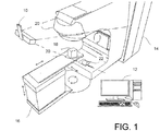
- FIG. 1 is a schematic perspective view of a treatment system.
- the treatment system includes a set of stereoscopic cameras 10 that are connected by wiring (not shown) to a computer 12.
- the computer 12 is also connected to treatment apparatus 14 such as a linear accelerator for applying radiotherapy.
- a mechanical couch 16 is provided as part of the treatment apparatus.
- the treatment apparatus 14 and the mechanical couch 16 are arranged such that, under the control of the computer 12, the relative positions of the mechanical couch 16 and the treatment apparatus 14 may be varied, laterally, vertically, longitudinally and rotationally as is indicated in the figure by the arrows adjacent the couch. Additionally the treatment apparatus 14 is also able to rotate about an axis as indicated by the arrows in the centre of the apparatus in the figure.
- the computer 12 is arranged to process images obtained by the stereoscopic cameras 10 to generate 3D wire mesh computer models of the surfaces of objects and people lying on the mechanical couch 16.
- a comparison of surface of a patient lying on the couch 16 with a reference surface of the same patient generated during the planning stage of treatment can enable the computer 12 to determine a transformation to match the two surfaces and generate a set of instructions to reposition the mechanical couch 16 so as to minimise differences between the surfaces.
- the patient can be treated using the treatment apparatus 14 in the knowledge that the patient is in the same position as the position used to determine treatment planning.
- the stereoscopic camera system 10 and the computer 12 are calibrated to the highest accuracy.
- the co-ordinate system used to generate 3D wire mesh models of the surface of a patient is matched both with the iso-centre of the treatment apparatus 14 and the axes of motion of the mechanical couch 16.
- the iso-centre of the treatment apparatus 14 will be the location of the zero co-ordinates for the modelling system and the axes of the co-ordinate system for the modelling system will be selected to correspond to the axes of motion (i.e. the lateral, vertical and horizontal axes of motion) of the mechanical couch 16. This then simplifies the conversion of transformations to match model surfaces in model space with instructions for relocating the mechanical couch 16 to match the position of a patient so that they can be treated using the treatment apparatus 14.
- Figure 2 is a flow diagram of a method of calibrating the treatment system of Figure 1 .
- the relative locations of the stereoscopic cameras in the stereoscopic camera system 10 are determined by imaging a calibration sheet such as is described in US7348974 and US7889906 . That is to say that a flat rigid calibration sheet such as a 70 ⁇ 70 cm sheet of material such as aluminium or steel on which a pattern revealing a matrix of circles at known positions on the surface of the sheet is placed on the mechanical couch and imaged by the stereoscopic cameras 10. On the sheet in addition to the pattern of circles are four smaller markers adjacent to four circles the centres of which together identify the four corners of a square of known size.
- the images of the sheet obtained by the cameras are then processed by the computer 12 to identify within the image the positions of the four markers in the images. From the relative positions of circles identified by the markers in the images, for each image a first projective transformation is determined which accounts for the estimated centres of the identified circles defining the corners of a projected distorted square in the image which arises due to the relative orientation of the calibration sheet and the camera obtaining the image.
- the calculated transform is then utilised to determine estimated three dimensional co-ordinate centres of each of the circles identified by markers. These calculated co-ordinates then identify an estimated location and orientation for the plane corresponding to the surface of the calibration sheet relative to the position from which an image has been obtained.
- Each pixel in the image obtained by the cameras 10 is then processed in turn to determine where within the plane containing the estimated positions of the circle centres, each pixel corresponds.
- the estimated circle centres are then processed in turn and the pixels in an image corresponding to points lying within a pre-determined distance from each circle centre in the calculated plane are then identified.
- the grey scale values for each of the pixels in each set are then utilised to determine an improved estimate of the co-ordinates for the circle centres.
- x and y co-ordinates for the positions of the points in the estimated plane including the surface of the calibration sheet each pixel represents within the set is determined.
- ⁇ g is the sum of all pixel values in the set identified for a particular circle centre
- ⁇ gx is the sum of the grey scale pixel values for a pixel multiplied by the x co-ordinates for those pixels
- ⁇ gy is the sum of the grey scale pixel values for a pixel multiplied by the y co-ordinates for those pixels
- the colour of the circle is associated with a high grey scale value and the colour of the background corresponding to the calibration sheet is associate with a low grey scale value.
- Co-ordinates for the point within the image corresponding to the new estimated circle centres are then determined from these x,y co-ordinates and these updated estimates of the centres of the marked circles are then utilised to determine a more accurate estimated transformation to account for the location and orientation of the calibration sheet. The above process can then be repeated until an accurate estimate of the actual circle centre positions is made and the true transform required to account for the relative orientation of the calibration sheet is determined.
- the expected positions of all of the circles on the sheet appearing in the image are then calculated, the portions of the images in the vicinity of each of the estimated circle centres are then processed individually in the same way as described above.
- a set of pixels is identified corresponding to points within a pre-set distance to the circle centre and then an improved circle centre co-ordinate is calculated using the grey scale values and co-ordinate values as described above.
- the relative orientation of the different cameras within the stereoscopic camera system 10 can then be calculated from the relative positions of these points in the images and the known relative locations of these circles on the surface of the calibration sheet as is described in detail in " A Versatile Camera Calibration Technique for High-Accuracy 3D Machine Vision Metrology Using Off the Shelf TV Cameras and Lenses", Roger Tsai, IEEE Journal of Robotics and Automation, Vol. Ra-3, No.4, August 1987 . Further from the relative positions of the points in the individual images internal camera parameters such as the focal length and radial distortion within the camera images can also be determined.
- the computer 12 is provided with data which enables the computer to convert stereoscopic images obtained by the stereoscopic camera system 10 into 3D computer wire mesh models of the surfaces of imaged objects. Further, since the initial calibration is performed relative to a calibration sheet of known dimensions, the computer is also provided with data identifying the relationship between distances in the computer models and real world measurements. However, at this stage there is no means by which the computer 12 can relate such measurements to the position of the iso-centre of the treatment room or the axes of motion of the mechanical couch.
- the phantom 18 in this embodiment, comprises a machined cube of known dimensions of a low density material with radiographic attenuation comparable to water and a density comparable to that of human tissue. In this embodiment, this is achieved by the phantom 18 being a machined polystyrene cube with the surface finish of the cube painted to provide optimal imagery for imaging by the stereoscopic camera system 10. In other embodiments other materials could be used. However in any embodiment the materials used should be selected to facilitate imaging using imaging techniques such as kV, stereo x-ray, MV or portal imaging, Cone Beam CT, and conventional axial and helical CT.
- imaging techniques such as kV, stereo x-ray, MV or portal imaging, Cone Beam CT, and conventional axial and helical CT.
- targets may comprise small metallic or ceramic balls.
- the balls may be made of steel, titanium or tungsten or may be made of a ceramic material or any other material which provides a good contrast to the material forming the body of the phantom 18 when the phantom is imaged.
- Most suitable materials will be materials which have good radiation stability which are able to withstand considerable radiation dose before undergoing substantial change where the relative density and radiographic attenuation of the targets provided within the body of the phantom 18 is selected to assist with the subsequent imaging of the phantom 18.
- any phantom 18 contains an asymmetrical arrangement of targets as the asymmetry of the targets enables the orientation of the phantom 18 to be determined from images of the phantom 18, enabling the orientation of the phantom 18 with respect to the treatment co-ordinate system to be determined or confirmed if already known.
- Suitable phantoms 18 with an asymmetric arrangement of imaging targets would include the Penta-Guide phantom (Modus Medical Devices, London Ontario, Canada) which consists of an acrylic cube of 16 cm size with five internal air pockets orientated in a unique pattern.
- Penta-Guide phantom Mode Medical Devices, London Ontario, Canada
- the phantom 18 is located at an estimated location for the iso-centre by being placed on an adjustable table 20 mounted on the mechanical couch 16.
- the adjustable table 20 in addition to fixing the location of the phantom 18 on the mechanical couch 16 is arranged to have adjustable feet so that minor adjustments to the orientation of the phantom can be made. This is desirable because the axes of motion of a typical mechanical couch 16 are limited to rotation and lateral, vertical and horizontal motion and hence motion of a mechanical couch 16 can only approximate changes in for example pitch or roll.
- the adjustable table 20 may include a spirit level which can indicate to a user when the table 20 and hence the phantom 18 is level.
- the adjustable table 20 is constructed from materials with low density/radiographic attenuation.
- the table 20 has a clear aperture in the path of the vertical treatment beam, so as not to adversely affect the quality of the radiographic images obtained when the phantom 18 is irradiated.
- the adjustable table 20 may be arranged so that it can only be attached to the mechanical couch 16 at a number of fixed locations and in fixed orientations relative to the surface of the mechanical couch 16. Similarly, the adjustable table 20 may also be arranged so that a phantom 18 may only be placed on the table 20 in one or more fixed orientations. Thus for example the adjustable table 20 may include a recess for receiving the phantom 18 in a particular orientation.
- the attachment of the adjustable table 20 to the mechanical couch 16 and the fixing of the position and orientation of the phantom 18 relative to the adjustable table 20 assists with fixing the positioning and orientation of the phantom relative to the iso-centre and co-ordinate system for the treatment room. In any event the adjustment table 20 should be constructed so as not to slip or move on the surface of the mechanical couch 16.
- the adjustable table may incorporate a micrometer positioning tool for precisely moving the phantom laterally, longitudinally and vertically.
- the advantage of such a positioning tool would be that it would be easier to make fine amendments to the position of the phantom using the tool rather than the mechanical couch 16 since the relocation would only involve movement of the phantom and not the entire couch 16.
- a phantom which incorporated such a tool might be utilized in place of a separate phantom 18 and adjustable table 20.
- An example of such a phantom would be the Varian Exact T Look-Bar (MedTec, Orange City, IA, USA) which consists of five markers embedded in a tissue equivalent material which is mountable on a couch via a cam lock mechanism which incorporates a micrometer tool.
- images of the phantom 18 are obtained (s3) using the stereoscopic cameras 10. These images are then processed by the computer 12 using the previously obtained information about the relative locations and internal parameters of the cameras of the stereoscopic camera system 10 to create a 3D computer model of the surface of the phantom 18 in the current 3D model space.
- the phantom 18 is then (s4) irradiated using the treatment apparatus 14 from a variety of angles and images of the projected radiation are obtained in a conventional manner in a similar way to the conventional Winston-Lutz test using a digital camera 22 arranged at a fixed point opposite the gantry head of the treatment apparatus 14 irradiating the phantom 18.
- the images obtained by the digital camera 22 when the gantry head of the treatment apparatus 14 is orientated in different locations are then processed by the computer 12 in a conventional way to determine from differences between the appearance of the phantom 18 in the images and in particular shadows of the targets contained within the phantom 18 and compared with the expected locations of shadows of the targets within the phantom on the assumption that the phantom 18 is correctly placed at the iso-centre. From this processing, the computer 12 determines the extent to which the centre of the phantom is offset from the true iso-centre of the treatment apparatus 14.
- the computer 12 then (s5) proceeds to apply the determined offset to the modelled surface of the phantom 18 to generate a reference surface for the correct positioning of the phantom 18. Having done so, the computer instructs the mechanical couch 16 to reposition itself laterally, vertically, longitudinally and rotationally so as to relocate the phantom 18 to the position of the true iso-centre. If the phantom 18 is correctly levelled prior to imaging an exact realignment of the phantom 18 should be achievable purely through lateral, vertical, longitudinal and rotational transformations.
- the location of the phantom 18 is monitored (s6) using the stereoscopic camera system 10 with the computer 12 processing images of the phantom 18 to generate a wire mesh models of the surface of the phantom 18 as it is repositioned. Any differences between the modelled surface and the original surface to which the required offset for relocating the phantom 18 to the true iso-centre can be displayed on the screen of the computer 12 to provide visual feedback of errors which remain.
- Monitoring of the motion of the phantom 18 provides an opportunity for confirming that the axes of the co-ordinate system being used to generate wire mesh models corresponds to the axes of the co-ordinate system for the mechanical couch 16. More specifically, the analysis of the images obtained by the digital camera 22 will provide an offset which is the offset for re-positioning the phantom 18 at the true iso-centre for the treatment room. Instructing the mechanical couch 16 to reposition the phantom 18 in a manner corresponding to the offset should result in a motion with corresponds which causes the phantom 18 to be correctly positioned.
- the motion of the phantom 18 due to the repositioning of the couch 16 should also correspond to an equivalent relocation of the surface of the phantom 18 as monitored by the stereoscopic camera system 10. Additionally, this monitoring of the surface of the phantom 18 can highlight the existence of any further minor adjustments to the position or orientation of the phantom 18 such as might be achieved by adjusting the adjustable table 20 after the phantom 18 has been repositioned by the mechanical couch 16.
- the stereoscopic camera 10 system can then use the images of the phantom 18 of known dimensions at a known location together with the known relative locations of the cameras of the stereoscopic camera system 10 to calibrate the co-ordinate system for the 3D surface models generated by the computer 12 relative to the actual location of the iso-centre. This is typically achieved by redefining the co-ordinate system for the computer model so that the origin for the computer model co-ordinate system coincides with the centre of the phantom 18 as determined from the modelled surface of the phantom 18 in its new position.
- Steps S3-S6 can be repeated if desired to obtain further confirmation to the relative position of the phantom 18 to the iso-centre. That is to say, after having relocated the mechanical couch 16 based on the determined offset based on images obtained by the digital camera 22 and monitoring that the phantom 18 has been correctly relocated using the stereoscopic camera system 10, the repositioned phantom 18 could then be re-irradiated and further images of the irradiated phantom 18 could then be obtained to confirm that the phantom 18 was indeed located at the iso-centre and if this was not the case further adjustments in the position of the phantom 18 could be made.
- a phantom 18 could be utilised comprising a single target where the phantom 18 comprises a cube of known dimensions with a single spherical target embedded in the cube where the sphere is located at the centre of the cube.
- Such a phantom 18 could then be imaged and adjustments made on the basis of analysis of images obtained by the digital camera 22 when the phantom is irradiated.
- the benefit of such a phantom 18 is that the target sphere could made to be very small and thereby assist with locating the iso-centre with greater accuracy.
- test phantom which consists of one central 2mm radio-opaque marker embedded in tissue equivalent material would be the Varian cube (Varian Medical Systems, Palo Alto, CA, USA).
- an adjustable table 20 is used which permits attachment of a phantom 18 in a single orientation.
- a phantom 18 containing multiple targets could be used to identify the location of the iso-centre of the treatment apparatus.
- Using the multi-target phantom would have the advantage that because of the asymmetric arrangement of target spheres is apparent, it is possible to determine the orientation of the phantom 18 as it appears in images obtained by the digital camera 22.
- the multi-target phantom 18 could then be replaced with a single target phantom 18 and final minor adjustments could be made to the calibration using the single target phantom.
- the stereoscopic camera system 10 could be utilised to ensure that no change in position occurred when the phantoms 18 were exchanged.
- the multiple phantoms 18 could be marked in a manner (e.g. colour coded) which enabled the individual phantoms 18 to be easily distinguished from one another.
- a phantom 18 could be positioned at the estimated location for an iso-centre and imaged using the stereoscopic camera system 18 and then irradiated with images being obtained using the digital camera 22. The images obtained by the digital camera 22 could then be processed to determine the offset of the phantom relative to the actual iso-centre for the treatment room.
- images of the phantom 18 obtained by the stereoscopic camera system 10 could be processed to generate a 3D computer model of the phantom at its current location.
- An adjustment for the co-ordinate system for the stereoscopic camera 10 could then be calculated by adding the transform calculated by processing the 3D model to relocate the centre of the model of phantom 18 with the origin of the axes for the computer model and the offset as determined by processing the images obtained by the digital camera 22.
Landscapes
- Engineering & Computer Science (AREA)
- Health & Medical Sciences (AREA)
- Life Sciences & Earth Sciences (AREA)
- Biomedical Technology (AREA)
- Nuclear Medicine, Radiotherapy & Molecular Imaging (AREA)
- Radiology & Medical Imaging (AREA)
- General Health & Medical Sciences (AREA)
- Animal Behavior & Ethology (AREA)
- Public Health (AREA)
- Veterinary Medicine (AREA)
- Physics & Mathematics (AREA)
- Pathology (AREA)
- Medical Informatics (AREA)
- Computer Vision & Pattern Recognition (AREA)
- Theoretical Computer Science (AREA)
- General Physics & Mathematics (AREA)
- Biophysics (AREA)
- Molecular Biology (AREA)
- Surgery (AREA)
- Heart & Thoracic Surgery (AREA)
- Optics & Photonics (AREA)
- High Energy & Nuclear Physics (AREA)
- Quality & Reliability (AREA)
- Apparatus For Radiation Diagnosis (AREA)
- Radiation-Therapy Devices (AREA)
Applications Claiming Priority (2)
| Application Number | Priority Date | Filing Date | Title |
|---|---|---|---|
| GB1312808.7A GB2516282B (en) | 2013-07-17 | 2013-07-17 | Method of calibration of a stereoscopic camera system for use with a radio therapy treatment apparatus |
| PCT/GB2014/052125 WO2015008040A2 (en) | 2013-07-17 | 2014-07-11 | Method of calibration of a stereoscopic camera system for use with a radio therapy treatment apparatus |
Publications (2)
| Publication Number | Publication Date |
|---|---|
| EP3021939A2 EP3021939A2 (en) | 2016-05-25 |
| EP3021939B1 true EP3021939B1 (en) | 2020-08-19 |
Family
ID=49081425
Family Applications (1)
| Application Number | Title | Priority Date | Filing Date |
|---|---|---|---|
| EP14739544.6A Active EP3021939B1 (en) | 2013-07-17 | 2014-07-11 | Method of calibration of a stereoscopic camera system for use with a radio therapy treatment apparatus |
Country Status (6)
| Country | Link |
|---|---|
| US (8) | US9962561B2 (enExample) |
| EP (1) | EP3021939B1 (enExample) |
| JP (1) | JP6284635B2 (enExample) |
| CN (1) | CN105473181B (enExample) |
| GB (1) | GB2516282B (enExample) |
| WO (1) | WO2015008040A2 (enExample) |
Families Citing this family (42)
| Publication number | Priority date | Publication date | Assignee | Title |
|---|---|---|---|---|
| GB2516282B (en) * | 2013-07-17 | 2017-07-26 | Vision Rt Ltd | Method of calibration of a stereoscopic camera system for use with a radio therapy treatment apparatus |
| GB2530790B (en) | 2014-10-02 | 2016-10-19 | Vision Rt Ltd | Method of calibrating a patient monitoring system for use with a radiotherapy treatment apparatus |
| US9420177B2 (en) | 2014-10-10 | 2016-08-16 | IEC Infrared Systems LLC | Panoramic view imaging system with laser range finding and blind spot detection |
| GB2532077B (en) | 2014-11-10 | 2017-11-22 | Vision Rt Ltd | Method of calibrating a patient monitoring system for use with a radiotherapy treatment apparatus |
| GB2538260B (en) | 2015-05-12 | 2017-07-05 | Vision Rt Ltd | A method of calibrating a sterescopic camera system |
| GB2538274B8 (en) * | 2015-05-13 | 2017-09-27 | Vision Rt Ltd | A target surface |
| JP6565080B2 (ja) * | 2015-08-11 | 2019-08-28 | 東芝エネルギーシステムズ株式会社 | 放射線治療装置、その作動方法及びプログラム |
| WO2018007518A1 (en) | 2016-07-06 | 2018-01-11 | Respiratory Innovations Pty Ltd | A realtime radiotherapy markerless calibration and measurement system |
| GB2561373A (en) * | 2017-04-11 | 2018-10-17 | Elekta ltd | Radiotherapy apparatus with calibration |
| US10569105B2 (en) * | 2017-05-26 | 2020-02-25 | Accuray Incorporated | Radiation based treatment beam position calibration and verification |
| GB2563256A (en) | 2017-06-07 | 2018-12-12 | Vision Rt Ltd | Patient monitoring system |
| KR102004467B1 (ko) * | 2017-06-23 | 2019-07-26 | 재단법인 아산사회복지재단 | 피부질환치료용 전자선 산란장치, 이를 포함하는 피부질환치료용 방사선치료시스템 및 이를 이용한 피부표면에 대한 호형 전자선 조사방법 |
| EP3421086B1 (en) * | 2017-06-28 | 2020-01-15 | OptiNav Sp. z o.o. | Determination of geometrical information about a medical treatment arrangement comprising a rotatable treatment radiation source unit |
| US11273326B2 (en) * | 2017-06-29 | 2022-03-15 | Canon Medical Systems Corporation | Radiotherapy system and treatment support apparatus |
| GB2565119A (en) * | 2017-08-02 | 2019-02-06 | Vision Rt Ltd | Method of calibrating a patient monitoring system for use with a radiotherapy treatment apparatus |
| GB2565306A (en) * | 2017-08-08 | 2019-02-13 | Vision Rt Ltd | Method and apparatus for measuring the accuracy of models generated by a patient monitoring system |
| CN107684669B (zh) | 2017-08-21 | 2020-04-17 | 上海联影医疗科技有限公司 | 用于校正对准设备的系统和方法 |
| CN107875524B (zh) * | 2017-11-10 | 2020-06-12 | 上海联影医疗科技有限公司 | 放射治疗系统、模体以及等中心校准方法 |
| WO2019136682A1 (zh) * | 2018-01-12 | 2019-07-18 | 新瑞阳光粒子医疗装备(无锡)有限公司 | 束流控制方法、装置、质子放疗系统及存储介质 |
| GB201802597D0 (en) | 2018-02-16 | 2018-04-04 | Vision Rt Ltd | A calibration object for calibrating a patient monitoring system |
| CN108937987B (zh) * | 2018-05-22 | 2021-07-02 | 上海联影医疗科技股份有限公司 | 一种确定模体中标记物位置的方法和系统 |
| DE102018115824B4 (de) | 2018-06-29 | 2021-04-22 | Carl Zeiss Meditec Ag | 3D-Kalibrierkörper, Kalibrierverfahren zum räumlichen Kalibrieren eines optischen Abbildungssystems, Kalibrierelement und Kalibrierverfahren zum Kalibrieren eines optischen Abbildungssystems |
| US12138484B2 (en) | 2018-07-12 | 2024-11-12 | Our United Corporation | Method and system for checking consistency between radiotherapy equipment isocenter and treatment isocenter |
| JP7078955B2 (ja) * | 2018-07-26 | 2022-06-01 | 東芝エネルギーシステムズ株式会社 | 治療システム、キャリブレーション方法、およびプログラム |
| CN109260612B (zh) * | 2018-11-28 | 2021-04-30 | 上海联影医疗科技股份有限公司 | 病床的位置参数检测方法、位置校正方法、装置及系统 |
| CN109464757B (zh) * | 2018-12-29 | 2021-07-20 | 上海联影医疗科技股份有限公司 | 一种确定目标对象位置的方法、系统、装置及存储介质 |
| CN109498051B (zh) * | 2018-12-30 | 2022-07-05 | 深圳安科高技术股份有限公司 | 一种ct病床机架自动位置校准方法及其系统 |
| CN110101977B (zh) * | 2019-05-07 | 2021-08-24 | 沈阳东软智睿放疗技术有限公司 | 一种实现医用直线加速器位置校准的方法及装置 |
| TR201912780A2 (tr) * | 2019-08-23 | 2021-03-22 | Deniz Celik | Akilli küp |
| WO2021072481A1 (en) * | 2019-10-14 | 2021-04-22 | Biline Calibrations | Medical linear accelerator calibration phantom |
| CN111632278B (zh) * | 2020-05-23 | 2022-04-19 | 四川中测辐射科技有限公司 | 利用多传感器进行三维射束分析仪的摆位误差修正方法 |
| CN115484869B (zh) * | 2020-08-07 | 2024-09-20 | 西安大医集团股份有限公司 | 图像数据的处理方法、放疗设备的等中心验证方法及系统 |
| CN112914591A (zh) * | 2021-02-23 | 2021-06-08 | 中科超精(南京)科技有限公司 | 一种图像引导系统校准装置及方法 |
| KR102556176B1 (ko) * | 2021-05-11 | 2023-07-14 | 영남대학교 산학협력단 | 방사선치료 선량 교정을 위한 워터 팬텀 정밀 자동 레벨링 방법 및 워터 팬텀 정밀 자동 레벨링 장치 |
| US12144671B2 (en) | 2021-12-22 | 2024-11-19 | Siemens Healthineers International Ag | Universal phantom for calibration and verification of optical and radiation systems |
| US12023522B2 (en) | 2022-04-14 | 2024-07-02 | Varian Medical Systems, Inc. | Phantom holder for radiation therapy system |
| DE102022109402A1 (de) | 2022-04-19 | 2023-10-19 | L A P Gmbh Laser Applikationen | Verfahren und System zum Unterstützen der Positionierung eines Patienten |
| CN114887239B (zh) * | 2022-04-28 | 2024-10-01 | 苏州雷泰医疗科技有限公司 | 基于epid的光栅全场自动标定方法、计算设备及存储介质 |
| US20240024703A1 (en) * | 2022-07-21 | 2024-01-25 | Radformation, Inc. | Modular Jig System |
| CN115999079B (zh) * | 2023-01-13 | 2025-09-19 | 南京大学 | 一种调强放疗设备等中心位置校准方法 |
| US20250078257A1 (en) * | 2023-09-01 | 2025-03-06 | Siemens Medical Solutions Usa, Inc. | Calibration of activity concentration uptake |
| CN120267327B (zh) * | 2025-06-09 | 2025-08-26 | 苏州波影医疗技术有限公司 | 扫描对象中心自动识别校准方法及ct系统 |
Citations (1)
| Publication number | Priority date | Publication date | Assignee | Title |
|---|---|---|---|---|
| US7889906B2 (en) * | 2002-07-08 | 2011-02-15 | Vision Rt Limited | Image processing system for use with a patient positioning device |
Family Cites Families (51)
| Publication number | Priority date | Publication date | Assignee | Title |
|---|---|---|---|---|
| US6345114B1 (en) * | 1995-06-14 | 2002-02-05 | Wisconsin Alumni Research Foundation | Method and apparatus for calibration of radiation therapy equipment and verification of radiation treatment |
| US7098435B2 (en) * | 1996-10-25 | 2006-08-29 | Frederick E. Mueller | Method and apparatus for scanning three-dimensional objects |
| US5859922A (en) * | 1997-02-21 | 1999-01-12 | Hoffmann; Kenneth R. | Process of determining the three-dimensional location of a pacemaker leads in the heart of a subject |
| US20020036617A1 (en) * | 1998-08-21 | 2002-03-28 | Timothy R. Pryor | Novel man machine interfaces and applications |
| US6636622B2 (en) * | 1997-10-15 | 2003-10-21 | Wisconsin Alumni Research Foundation | Method and apparatus for calibration of radiation therapy equipment and verification of radiation treatment |
| US6990228B1 (en) * | 1999-12-17 | 2006-01-24 | Canon Kabushiki Kaisha | Image processing apparatus |
| US6856826B2 (en) * | 2000-04-28 | 2005-02-15 | Ge Medical Systems Global Technology Company, Llc | Fluoroscopic tracking and visualization system |
| US6490475B1 (en) * | 2000-04-28 | 2002-12-03 | Ge Medical Systems Global Technology Company, Llc | Fluoroscopic tracking and visualization system |
| TWI229037B (en) | 2000-09-29 | 2005-03-11 | Toray Industries | Fiber structure of heat retaining property |
| US6385287B1 (en) * | 2000-12-06 | 2002-05-07 | Siemens Medical Solutions Usa, Inc. | Method and system for providing virtual grid for portal imaging in a radiotherapy system |
| SE522162C2 (sv) * | 2002-05-06 | 2004-01-20 | Goergen Nilsson | Metod att utföra in vivo-dosimetri vid IMRT-behandling |
| DE10231630A1 (de) * | 2002-07-12 | 2004-01-29 | Brainlab Ag | System zur Patientenpositionierung für die Strahlentherapie/Radiochirurgie basierend auf einer stereoskopischen Röntgenanlage |
| GB0305315D0 (en) * | 2003-03-07 | 2003-04-09 | Weber Martin | Image processing system |
| US20060259282A1 (en) * | 2003-03-14 | 2006-11-16 | Failla Gregory A | Deterministic computation of radiation transport for radiotherapy dose calculations and scatter correction for image reconstruction |
| US20050089213A1 (en) * | 2003-10-23 | 2005-04-28 | Geng Z. J. | Method and apparatus for three-dimensional modeling via an image mosaic system |
| US9493769B2 (en) | 2004-06-02 | 2016-11-15 | Universite D'aix-Marseille | Yeast-based assay for measuring the functional activity of an HIV-1 protease in response to an antiviral agent |
| US8787164B2 (en) | 2004-07-09 | 2014-07-22 | Qualcomm Incorporated | Media delivery system and method for transporting media to desired target devices |
| GB2418495B (en) * | 2004-09-24 | 2010-04-28 | Vision Rt Ltd | Image processing system for use with a patient positioning device |
| JP2007043225A (ja) * | 2005-07-29 | 2007-02-15 | Univ Of Electro-Communications | 撮像画像処理装置及び撮像画像処理方法 |
| EP1920383A4 (en) * | 2005-09-06 | 2010-12-22 | Identification International I | ALORITMIC CORRECTION OF IMAGE FORMATION IN A FINGERPRINT PICTURE SYSTEM |
| US20080219405A1 (en) * | 2005-09-06 | 2008-09-11 | Tony Falco | System and method for patient setup for radiotherapy treatment |
| JP2007101197A (ja) * | 2005-09-30 | 2007-04-19 | Nachi Fujikoshi Corp | 物体探索装置,物体探索装置を備えるロボットシステム及び物体探索方法 |
| KR100809521B1 (ko) * | 2005-12-08 | 2008-03-04 | 한국전자통신연구원 | 복수의 영상간 대응곡선을 이용한 3차원 곡면 생성 기법 |
| GB2441550A (en) | 2006-09-05 | 2008-03-12 | Vision Rt Ltd | Surface-imaging breathing monitor |
| US8385623B2 (en) * | 2007-07-11 | 2013-02-26 | Shimadzu Corporation | Radiographic apparatus |
| US8441476B2 (en) * | 2007-11-16 | 2013-05-14 | Sportvision, Inc. | Image repair interface for providing virtual viewpoints |
| WO2013116694A1 (en) * | 2012-02-03 | 2013-08-08 | The Trustees Of Dartmouth College | Method and apparatus for determining tumor shift during surgery using a stereo-optical three-dimensional surface-mapping system |
| DE102008060141B4 (de) * | 2008-12-03 | 2017-12-21 | Forschungszentrum Jülich GmbH | Verfahren zur Vermessung des Wachstums von Blattscheiben sowie eine dazu geeignete Vorrichtung |
| KR101708516B1 (ko) * | 2008-12-03 | 2017-02-27 | 대니얼 나바로 | 방사선 빔 애널라이저 및 방법 |
| US8602647B2 (en) * | 2008-12-03 | 2013-12-10 | Daniel Navarro | Radiation beam analyzer and method |
| US8039790B2 (en) * | 2009-05-14 | 2011-10-18 | University Health Network | Phantoms and methods for verification in radiotherapy systems |
| WO2011098891A1 (en) * | 2010-02-09 | 2011-08-18 | Hans Schiefer | Rotationally symmetrical coherent verification phantom (virtual patient) with a flat detector disposed on a rotary axis integrated in a multi purpose qc-accessory |
| US8488862B2 (en) * | 2010-06-09 | 2013-07-16 | Siemens Medical Solutions Usa, Inc. | Characterization of source trajectory for radiotherapy |
| JP2012085703A (ja) * | 2010-10-15 | 2012-05-10 | Toshiba Corp | 放射線治療システム及びその精度管理用ファントム |
| CN102049106B (zh) * | 2010-12-14 | 2012-07-25 | 张岩 | 分次放射治疗间放疗系统的精确影像定位系统及方法 |
| US9572539B2 (en) * | 2011-04-08 | 2017-02-21 | Imactis | Device and method for determining the position of an instrument in relation to medical images |
| CN103517736B (zh) * | 2011-04-29 | 2016-06-29 | 医科达公司 | 标定和质量保证的方法 |
| US20120330083A1 (en) * | 2011-06-22 | 2012-12-27 | The Christie NHS Foundation Trust | Radiotherapy phantom |
| US10758209B2 (en) * | 2012-03-09 | 2020-09-01 | The Johns Hopkins University | Photoacoustic tracking and registration in interventional ultrasound |
| US9538940B2 (en) * | 2012-05-03 | 2017-01-10 | University of Pittsburgh—of the Commonwealth System of Higher Education | Intelligent algorithms for tracking three-dimensional skeletal movement from radiographic image sequences |
| EP2910009A4 (en) * | 2012-10-17 | 2016-07-27 | Gelsight Inc | THREE DIMENSIONAL DIGITAL PRINTING AND VISUALIZATION OF OBJECTS |
| US20140222444A1 (en) * | 2013-02-04 | 2014-08-07 | Dixit S.R.L. | Method And System For Clinical Trial Management |
| GB2516282B (en) * | 2013-07-17 | 2017-07-26 | Vision Rt Ltd | Method of calibration of a stereoscopic camera system for use with a radio therapy treatment apparatus |
| GB2532077B (en) * | 2014-11-10 | 2017-11-22 | Vision Rt Ltd | Method of calibrating a patient monitoring system for use with a radiotherapy treatment apparatus |
| GB2538260B (en) * | 2015-05-12 | 2017-07-05 | Vision Rt Ltd | A method of calibrating a sterescopic camera system |
| US10539642B2 (en) * | 2015-09-15 | 2020-01-21 | Koninklijke Philips N.V. | Method for calibrating a magnetic resonance imaging (MRI) phantom |
| WO2017191207A1 (en) * | 2016-05-04 | 2017-11-09 | Brainlab Ag | Monitoring a patient's position using a planning image and subsequent thermal imaging |
| EP3589366B1 (en) * | 2017-02-28 | 2025-12-10 | Sun Nuclear Corporation | Radiation therapy treatment verification with electronic portal imaging device transit images |
| GB201802597D0 (en) * | 2018-02-16 | 2018-04-04 | Vision Rt Ltd | A calibration object for calibrating a patient monitoring system |
| US11600004B2 (en) * | 2019-07-10 | 2023-03-07 | Sun Nuclear Corporation | Image-based radiation therapy quality assurance |
| US12144671B2 (en) * | 2021-12-22 | 2024-11-19 | Siemens Healthineers International Ag | Universal phantom for calibration and verification of optical and radiation systems |
-
2013
- 2013-07-17 GB GB1312808.7A patent/GB2516282B/en active Active
-
2014
- 2014-07-11 JP JP2016526691A patent/JP6284635B2/ja active Active
- 2014-07-11 CN CN201480040129.3A patent/CN105473181B/zh active Active
- 2014-07-11 US US14/899,112 patent/US9962561B2/en active Active
- 2014-07-11 WO PCT/GB2014/052125 patent/WO2015008040A2/en not_active Ceased
- 2014-07-11 EP EP14739544.6A patent/EP3021939B1/en active Active
-
2018
- 2018-04-05 US US15/946,362 patent/US10456601B2/en active Active
-
2019
- 2019-09-23 US US16/578,905 patent/US10933258B2/en active Active
-
2021
- 2021-01-27 US US17/159,845 patent/US11633629B2/en active Active
-
2023
- 2023-03-21 US US18/124,273 patent/US12220601B2/en active Active
- 2023-10-16 US US18/487,148 patent/US12251580B2/en active Active
- 2023-12-18 US US18/542,832 patent/US12042671B2/en active Active
-
2025
- 2025-02-12 US US19/051,239 patent/US20250249288A1/en active Pending
Patent Citations (1)
| Publication number | Priority date | Publication date | Assignee | Title |
|---|---|---|---|---|
| US7889906B2 (en) * | 2002-07-08 | 2011-02-15 | Vision Rt Limited | Image processing system for use with a patient positioning device |
Non-Patent Citations (2)
| Title |
|---|
| GRELEWICZ ZACHARY ET AL: "An EPID based method for performing high accuracy calibration between an optical external marker tracking device and the LINAC reference frame", MEDICAL PHYSICS, AIP, MELVILLE, NY, US, vol. 39, no. 5, 1 May 2012 (2012-05-01), pages 2771 - 2779, XP012161035, ISSN: 0094-2405, [retrieved on 20120424], DOI: 10.1118/1.3703836 * |
| TIDEMAN ARP DENNIS ET AL: "x-ray and beam isocenters-What's the dif", MEDICAL PHYSICS, AIP, MELVILLE, NY, US, vol. 39, no. 3, 1 March 2012 (2012-03-01), pages 1418 - 1423, XP012160894, ISSN: 0094-2405, [retrieved on 20120223], DOI: 10.1118/1.3685581 * |
Also Published As
| Publication number | Publication date |
|---|---|
| JP6284635B2 (ja) | 2018-02-28 |
| US20180221686A1 (en) | 2018-08-09 |
| US20160129283A1 (en) | 2016-05-12 |
| US20230330438A1 (en) | 2023-10-19 |
| EP3021939A2 (en) | 2016-05-25 |
| CN105473181A (zh) | 2016-04-06 |
| US20250249288A1 (en) | 2025-08-07 |
| US20240123260A1 (en) | 2024-04-18 |
| US11633629B2 (en) | 2023-04-25 |
| US20240042241A1 (en) | 2024-02-08 |
| CN105473181B (zh) | 2019-03-05 |
| US12042671B2 (en) | 2024-07-23 |
| US12220601B2 (en) | 2025-02-11 |
| US10456601B2 (en) | 2019-10-29 |
| US10933258B2 (en) | 2021-03-02 |
| GB201312808D0 (en) | 2013-08-28 |
| US9962561B2 (en) | 2018-05-08 |
| US20200016434A1 (en) | 2020-01-16 |
| US12251580B2 (en) | 2025-03-18 |
| GB2516282A (en) | 2015-01-21 |
| WO2015008040A2 (en) | 2015-01-22 |
| JP2016524983A (ja) | 2016-08-22 |
| WO2015008040A3 (en) | 2015-05-21 |
| US20210146162A1 (en) | 2021-05-20 |
| GB2516282B (en) | 2017-07-26 |
Similar Documents
| Publication | Publication Date | Title |
|---|---|---|
| US12220601B2 (en) | Method of calibration of a stereoscopic camera system for use with a radio therapy treatment apparatus | |
| Antypas et al. | Performance evaluation of a CyberKnife® G4 image-guided robotic stereotactic radiosurgery system | |
| US6516046B1 (en) | Exact patient positioning by compairing reconstructed x-ray images and linac x-ray images | |
| CN111132730B (zh) | 与放射治疗设备一起使用的患者监测系统的校准方法 | |
| US8845191B2 (en) | Compound 6D-offset simulating phantom and quality assurance program for precision image-guided radiotherapy and radiosurgery | |
| CN111432878B (zh) | 放射治疗装置的等中心的基于epid的验证、修正和最小化的方法 | |
| EP4201333A1 (en) | Universal phantom for calibration and verification of optical and radiation systems | |
| US20180345040A1 (en) | A target surface | |
| Hayashi et al. | Assessment of spatial uncertainties in the radiotherapy process with the Novalis system | |
| Sutton et al. | Accuracy and precision of cone-beam computed tomography guided intensity modulated radiation therapy | |
| Pantelis et al. | Quality Control | |
| Park et al. | Feasibility of an In-House Phantom for Mechanical and Geometrical QA | |
| Torfeh et al. | 3D numerical test objects for the evaluation of a software used for an automatic analysis of a linear accelerator mechanical stability |
Legal Events
| Date | Code | Title | Description |
|---|---|---|---|
| PUAI | Public reference made under article 153(3) epc to a published international application that has entered the european phase |
Free format text: ORIGINAL CODE: 0009012 |
|
| 17P | Request for examination filed |
Effective date: 20160205 |
|
| AK | Designated contracting states |
Kind code of ref document: A2 Designated state(s): AL AT BE BG CH CY CZ DE DK EE ES FI FR GB GR HR HU IE IS IT LI LT LU LV MC MK MT NL NO PL PT RO RS SE SI SK SM TR |
|
| AX | Request for extension of the european patent |
Extension state: BA ME |
|
| DAX | Request for extension of the european patent (deleted) | ||
| PUAG | Search results despatched under rule 164(2) epc together with communication from examining division |
Free format text: ORIGINAL CODE: 0009017 |
|
| STAA | Information on the status of an ep patent application or granted ep patent |
Free format text: STATUS: EXAMINATION IS IN PROGRESS |
|
| 17Q | First examination report despatched |
Effective date: 20171207 |
|
| B565 | Issuance of search results under rule 164(2) epc |
Effective date: 20171207 |
|
| RIC1 | Information provided on ipc code assigned before grant |
Ipc: G06T 7/00 20170101ALI20171204BHEP Ipc: A61B 6/00 20060101ALI20171204BHEP Ipc: A61N 5/10 20060101AFI20171204BHEP |
|
| GRAP | Despatch of communication of intention to grant a patent |
Free format text: ORIGINAL CODE: EPIDOSNIGR1 |
|
| STAA | Information on the status of an ep patent application or granted ep patent |
Free format text: STATUS: GRANT OF PATENT IS INTENDED |
|
| INTG | Intention to grant announced |
Effective date: 20200312 |
|
| GRAS | Grant fee paid |
Free format text: ORIGINAL CODE: EPIDOSNIGR3 |
|
| GRAA | (expected) grant |
Free format text: ORIGINAL CODE: 0009210 |
|
| STAA | Information on the status of an ep patent application or granted ep patent |
Free format text: STATUS: THE PATENT HAS BEEN GRANTED |
|
| AK | Designated contracting states |
Kind code of ref document: B1 Designated state(s): AL AT BE BG CH CY CZ DE DK EE ES FI FR GB GR HR HU IE IS IT LI LT LU LV MC MK MT NL NO PL PT RO RS SE SI SK SM TR |
|
| REG | Reference to a national code |
Ref country code: CH Ref legal event code: EP |
|
| REG | Reference to a national code |
Ref country code: DE Ref legal event code: R096 Ref document number: 602014069133 Country of ref document: DE |
|
| REG | Reference to a national code |
Ref country code: AT Ref legal event code: REF Ref document number: 1303269 Country of ref document: AT Kind code of ref document: T Effective date: 20200915 |
|
| REG | Reference to a national code |
Ref country code: IE Ref legal event code: FG4D |
|
| REG | Reference to a national code |
Ref country code: SE Ref legal event code: TRGR |
|
| REG | Reference to a national code |
Ref country code: LT Ref legal event code: MG4D |
|
| REG | Reference to a national code |
Ref country code: NL Ref legal event code: MP Effective date: 20200819 |
|
| PG25 | Lapsed in a contracting state [announced via postgrant information from national office to epo] |
Ref country code: BG Free format text: LAPSE BECAUSE OF FAILURE TO SUBMIT A TRANSLATION OF THE DESCRIPTION OR TO PAY THE FEE WITHIN THE PRESCRIBED TIME-LIMIT Effective date: 20201119 Ref country code: PT Free format text: LAPSE BECAUSE OF FAILURE TO SUBMIT A TRANSLATION OF THE DESCRIPTION OR TO PAY THE FEE WITHIN THE PRESCRIBED TIME-LIMIT Effective date: 20201221 Ref country code: NO Free format text: LAPSE BECAUSE OF FAILURE TO SUBMIT A TRANSLATION OF THE DESCRIPTION OR TO PAY THE FEE WITHIN THE PRESCRIBED TIME-LIMIT Effective date: 20201119 Ref country code: FI Free format text: LAPSE BECAUSE OF FAILURE TO SUBMIT A TRANSLATION OF THE DESCRIPTION OR TO PAY THE FEE WITHIN THE PRESCRIBED TIME-LIMIT Effective date: 20200819 Ref country code: GR Free format text: LAPSE BECAUSE OF FAILURE TO SUBMIT A TRANSLATION OF THE DESCRIPTION OR TO PAY THE FEE WITHIN THE PRESCRIBED TIME-LIMIT Effective date: 20201120 Ref country code: LT Free format text: LAPSE BECAUSE OF FAILURE TO SUBMIT A TRANSLATION OF THE DESCRIPTION OR TO PAY THE FEE WITHIN THE PRESCRIBED TIME-LIMIT Effective date: 20200819 Ref country code: HR Free format text: LAPSE BECAUSE OF FAILURE TO SUBMIT A TRANSLATION OF THE DESCRIPTION OR TO PAY THE FEE WITHIN THE PRESCRIBED TIME-LIMIT Effective date: 20200819 |
|
| REG | Reference to a national code |
Ref country code: AT Ref legal event code: MK05 Ref document number: 1303269 Country of ref document: AT Kind code of ref document: T Effective date: 20200819 |
|
| PG25 | Lapsed in a contracting state [announced via postgrant information from national office to epo] |
Ref country code: LV Free format text: LAPSE BECAUSE OF FAILURE TO SUBMIT A TRANSLATION OF THE DESCRIPTION OR TO PAY THE FEE WITHIN THE PRESCRIBED TIME-LIMIT Effective date: 20200819 Ref country code: NL Free format text: LAPSE BECAUSE OF FAILURE TO SUBMIT A TRANSLATION OF THE DESCRIPTION OR TO PAY THE FEE WITHIN THE PRESCRIBED TIME-LIMIT Effective date: 20200819 Ref country code: RS Free format text: LAPSE BECAUSE OF FAILURE TO SUBMIT A TRANSLATION OF THE DESCRIPTION OR TO PAY THE FEE WITHIN THE PRESCRIBED TIME-LIMIT Effective date: 20200819 Ref country code: PL Free format text: LAPSE BECAUSE OF FAILURE TO SUBMIT A TRANSLATION OF THE DESCRIPTION OR TO PAY THE FEE WITHIN THE PRESCRIBED TIME-LIMIT Effective date: 20200819 Ref country code: IS Free format text: LAPSE BECAUSE OF FAILURE TO SUBMIT A TRANSLATION OF THE DESCRIPTION OR TO PAY THE FEE WITHIN THE PRESCRIBED TIME-LIMIT Effective date: 20201219 |
|
| PG25 | Lapsed in a contracting state [announced via postgrant information from national office to epo] |
Ref country code: SM Free format text: LAPSE BECAUSE OF FAILURE TO SUBMIT A TRANSLATION OF THE DESCRIPTION OR TO PAY THE FEE WITHIN THE PRESCRIBED TIME-LIMIT Effective date: 20200819 Ref country code: RO Free format text: LAPSE BECAUSE OF FAILURE TO SUBMIT A TRANSLATION OF THE DESCRIPTION OR TO PAY THE FEE WITHIN THE PRESCRIBED TIME-LIMIT Effective date: 20200819 Ref country code: DK Free format text: LAPSE BECAUSE OF FAILURE TO SUBMIT A TRANSLATION OF THE DESCRIPTION OR TO PAY THE FEE WITHIN THE PRESCRIBED TIME-LIMIT Effective date: 20200819 Ref country code: CZ Free format text: LAPSE BECAUSE OF FAILURE TO SUBMIT A TRANSLATION OF THE DESCRIPTION OR TO PAY THE FEE WITHIN THE PRESCRIBED TIME-LIMIT Effective date: 20200819 Ref country code: EE Free format text: LAPSE BECAUSE OF FAILURE TO SUBMIT A TRANSLATION OF THE DESCRIPTION OR TO PAY THE FEE WITHIN THE PRESCRIBED TIME-LIMIT Effective date: 20200819 |
|
| REG | Reference to a national code |
Ref country code: DE Ref legal event code: R097 Ref document number: 602014069133 Country of ref document: DE |
|
| PG25 | Lapsed in a contracting state [announced via postgrant information from national office to epo] |
Ref country code: AT Free format text: LAPSE BECAUSE OF FAILURE TO SUBMIT A TRANSLATION OF THE DESCRIPTION OR TO PAY THE FEE WITHIN THE PRESCRIBED TIME-LIMIT Effective date: 20200819 Ref country code: AL Free format text: LAPSE BECAUSE OF FAILURE TO SUBMIT A TRANSLATION OF THE DESCRIPTION OR TO PAY THE FEE WITHIN THE PRESCRIBED TIME-LIMIT Effective date: 20200819 Ref country code: ES Free format text: LAPSE BECAUSE OF FAILURE TO SUBMIT A TRANSLATION OF THE DESCRIPTION OR TO PAY THE FEE WITHIN THE PRESCRIBED TIME-LIMIT Effective date: 20200819 |
|
| PLBE | No opposition filed within time limit |
Free format text: ORIGINAL CODE: 0009261 |
|
| STAA | Information on the status of an ep patent application or granted ep patent |
Free format text: STATUS: NO OPPOSITION FILED WITHIN TIME LIMIT |
|
| PG25 | Lapsed in a contracting state [announced via postgrant information from national office to epo] |
Ref country code: SK Free format text: LAPSE BECAUSE OF FAILURE TO SUBMIT A TRANSLATION OF THE DESCRIPTION OR TO PAY THE FEE WITHIN THE PRESCRIBED TIME-LIMIT Effective date: 20200819 |
|
| 26N | No opposition filed |
Effective date: 20210520 |
|
| PG25 | Lapsed in a contracting state [announced via postgrant information from national office to epo] |
Ref country code: IT Free format text: LAPSE BECAUSE OF FAILURE TO SUBMIT A TRANSLATION OF THE DESCRIPTION OR TO PAY THE FEE WITHIN THE PRESCRIBED TIME-LIMIT Effective date: 20200819 |
|
| PG25 | Lapsed in a contracting state [announced via postgrant information from national office to epo] |
Ref country code: SI Free format text: LAPSE BECAUSE OF FAILURE TO SUBMIT A TRANSLATION OF THE DESCRIPTION OR TO PAY THE FEE WITHIN THE PRESCRIBED TIME-LIMIT Effective date: 20200819 |
|
| PG25 | Lapsed in a contracting state [announced via postgrant information from national office to epo] |
Ref country code: MC Free format text: LAPSE BECAUSE OF FAILURE TO SUBMIT A TRANSLATION OF THE DESCRIPTION OR TO PAY THE FEE WITHIN THE PRESCRIBED TIME-LIMIT Effective date: 20200819 |
|
| REG | Reference to a national code |
Ref country code: BE Ref legal event code: MM Effective date: 20210731 |
|
| PG25 | Lapsed in a contracting state [announced via postgrant information from national office to epo] |
Ref country code: LU Free format text: LAPSE BECAUSE OF NON-PAYMENT OF DUE FEES Effective date: 20210711 |
|
| PG25 | Lapsed in a contracting state [announced via postgrant information from national office to epo] |
Ref country code: IE Free format text: LAPSE BECAUSE OF NON-PAYMENT OF DUE FEES Effective date: 20210711 Ref country code: BE Free format text: LAPSE BECAUSE OF NON-PAYMENT OF DUE FEES Effective date: 20210731 |
|
| PG25 | Lapsed in a contracting state [announced via postgrant information from national office to epo] |
Ref country code: HU Free format text: LAPSE BECAUSE OF FAILURE TO SUBMIT A TRANSLATION OF THE DESCRIPTION OR TO PAY THE FEE WITHIN THE PRESCRIBED TIME-LIMIT; INVALID AB INITIO Effective date: 20140711 |
|
| PG25 | Lapsed in a contracting state [announced via postgrant information from national office to epo] |
Ref country code: CY Free format text: LAPSE BECAUSE OF FAILURE TO SUBMIT A TRANSLATION OF THE DESCRIPTION OR TO PAY THE FEE WITHIN THE PRESCRIBED TIME-LIMIT Effective date: 20200819 |
|
| PG25 | Lapsed in a contracting state [announced via postgrant information from national office to epo] |
Ref country code: MK Free format text: LAPSE BECAUSE OF FAILURE TO SUBMIT A TRANSLATION OF THE DESCRIPTION OR TO PAY THE FEE WITHIN THE PRESCRIBED TIME-LIMIT Effective date: 20200819 |
|
| PG25 | Lapsed in a contracting state [announced via postgrant information from national office to epo] |
Ref country code: TR Free format text: LAPSE BECAUSE OF FAILURE TO SUBMIT A TRANSLATION OF THE DESCRIPTION OR TO PAY THE FEE WITHIN THE PRESCRIBED TIME-LIMIT Effective date: 20200819 |
|
| PG25 | Lapsed in a contracting state [announced via postgrant information from national office to epo] |
Ref country code: MT Free format text: LAPSE BECAUSE OF FAILURE TO SUBMIT A TRANSLATION OF THE DESCRIPTION OR TO PAY THE FEE WITHIN THE PRESCRIBED TIME-LIMIT Effective date: 20200819 |
|
| PGFP | Annual fee paid to national office [announced via postgrant information from national office to epo] |
Ref country code: GB Payment date: 20250626 Year of fee payment: 12 |
|
| PGFP | Annual fee paid to national office [announced via postgrant information from national office to epo] |
Ref country code: FR Payment date: 20250626 Year of fee payment: 12 |
|
| PGFP | Annual fee paid to national office [announced via postgrant information from national office to epo] |
Ref country code: SE Payment date: 20250626 Year of fee payment: 12 |
|
| PGFP | Annual fee paid to national office [announced via postgrant information from national office to epo] |
Ref country code: DE Payment date: 20250627 Year of fee payment: 12 |
|
| PGFP | Annual fee paid to national office [announced via postgrant information from national office to epo] |
Ref country code: CH Payment date: 20250801 Year of fee payment: 12 |