EP3021102A1 - Banc d'essai pour turbomachine axiale avec eolienne verticale - Google Patents
Banc d'essai pour turbomachine axiale avec eolienne verticale Download PDFInfo
- Publication number
- EP3021102A1 EP3021102A1 EP15194001.2A EP15194001A EP3021102A1 EP 3021102 A1 EP3021102 A1 EP 3021102A1 EP 15194001 A EP15194001 A EP 15194001A EP 3021102 A1 EP3021102 A1 EP 3021102A1
- Authority
- EP
- European Patent Office
- Prior art keywords
- wind turbine
- vertical
- test
- turbomachine
- wind turbines
- Prior art date
- Legal status (The legal status is an assumption and is not a legal conclusion. Google has not performed a legal analysis and makes no representation as to the accuracy of the status listed.)
- Granted
Links
Images

Classifications
-
- G—PHYSICS
- G01—MEASURING; TESTING
- G01M—TESTING STATIC OR DYNAMIC BALANCE OF MACHINES OR STRUCTURES; TESTING OF STRUCTURES OR APPARATUS, NOT OTHERWISE PROVIDED FOR
- G01M15/00—Testing of engines
- G01M15/14—Testing gas-turbine engines or jet-propulsion engines
-
- F—MECHANICAL ENGINEERING; LIGHTING; HEATING; WEAPONS; BLASTING
- F01—MACHINES OR ENGINES IN GENERAL; ENGINE PLANTS IN GENERAL; STEAM ENGINES
- F01D—NON-POSITIVE DISPLACEMENT MACHINES OR ENGINES, e.g. STEAM TURBINES
- F01D15/00—Adaptations of machines or engines for special use; Combinations of engines with devices driven thereby
- F01D15/10—Adaptations for driving, or combinations with, electric generators
-
- F—MECHANICAL ENGINEERING; LIGHTING; HEATING; WEAPONS; BLASTING
- F01—MACHINES OR ENGINES IN GENERAL; ENGINE PLANTS IN GENERAL; STEAM ENGINES
- F01D—NON-POSITIVE DISPLACEMENT MACHINES OR ENGINES, e.g. STEAM TURBINES
- F01D21/00—Shutting-down of machines or engines, e.g. in emergency; Regulating, controlling, or safety means not otherwise provided for
- F01D21/003—Arrangements for testing or measuring
-
- F—MECHANICAL ENGINEERING; LIGHTING; HEATING; WEAPONS; BLASTING
- F02—COMBUSTION ENGINES; HOT-GAS OR COMBUSTION-PRODUCT ENGINE PLANTS
- F02C—GAS-TURBINE PLANTS; AIR INTAKES FOR JET-PROPULSION PLANTS; CONTROLLING FUEL SUPPLY IN AIR-BREATHING JET-PROPULSION PLANTS
- F02C7/00—Features, components parts, details or accessories, not provided for in, or of interest apart form groups F02C1/00 - F02C6/00; Air intakes for jet-propulsion plants
- F02C7/20—Mounting or supporting of plant; Accommodating heat expansion or creep
-
- F—MECHANICAL ENGINEERING; LIGHTING; HEATING; WEAPONS; BLASTING
- F05—INDEXING SCHEMES RELATING TO ENGINES OR PUMPS IN VARIOUS SUBCLASSES OF CLASSES F01-F04
- F05B—INDEXING SCHEME RELATING TO WIND, SPRING, WEIGHT, INERTIA OR LIKE MOTORS, TO MACHINES OR ENGINES FOR LIQUIDS COVERED BY SUBCLASSES F03B, F03D AND F03G
- F05B2220/00—Application
- F05B2220/60—Application making use of surplus or waste energy
- F05B2220/602—Application making use of surplus or waste energy with energy recovery turbines
Definitions
- the invention relates to a test stand for a turbomachine. More particularly, the invention relates to a turbomachine test stand configured for energy recovery generated during a test.
- the patent document WO 2012/171105 A1 discloses a test bench for a turbomachine comprising an energy recovery system.
- the system recovers the kinetic energy of a mixture of combustion gases and air moving in the test stand and converts this kinetic energy into electricity by means of a wind turbine.
- the turbomachine is located in a test chamber and the wind turbine is located in a tube downstream of the test chamber.
- the tube is commonly called “collector tube” in that it collects the combustion gases leaving the turbomachine.
- the high velocity of the combustion gases in the tube makes it possible to draw a minimum of ambient air around the turbomachine so as to satisfy the test conditions required in terms of the minimum air flow in the test chamber.
- the collector tube acts as a kind of pump of the gas mixture with a view to its expulsion, it also avoids localized inversions of the flow downstream of the turbomachine.
- the collecting tube may in particular be configured to absorb the sound waves downstream of the turbomachine.
- the wind turbine comprises blades with variable pitch to adapt to the different flow rates of the gas mixture reached depending on the size of the turbomachines tested; it is connected to an alternator / generator to generate electricity. This teaching is interesting in that the wind turbine positioned in the collector tube receives a substantially laminar gas mixture flow. In addition, the tube limits the size of the wind turbine.
- the teaching is however limited to turbine engine tests for which the speed and the pressure of the exhaust gases of the turbomachine, modified by the presence of the wind turbine in the tube, always guarantee the minimum of ambient air suction. the test chamber necessary for the test. Furthermore, the position of the wind turbine in the tube receiving a gas mixture of high temperature combustion products imposes operating constraints on the wind turbine which increases the cost.
- the patent document EP 2 336 507 A1 discloses a turbomachine test stand comprising a turbine for recovering the kinetic energy of exhaust gas from the turbomachine.
- the turbine is disposed between a test chamber, upstream, in which the turbomachine is located, and an exhaust gas expulsion chamber, downstream.
- the turbine is configured to replace the function of a conventional header tube which is generally of significant length.
- the turbine is able to absorb sound waves, for example infrasound.
- the rotor of the turbine on which are mounted the blades rotated by the kinetic energy of the gas flow also comprises a propeller operating as a fan so as to balance the air pressures between the test chamber and the chamber. expulsion according to the turbomachines tested.
- This teaching is interesting in that the test bench is substantially compact.
- turbomachines for which the temperature of the exhaust gas does not exceed a critical threshold for the components of the turbine.
- the turbine forms a brake on the flow of gases downstream of the engine, and localized inversions of the flow can disturb the test of turbomachines.
- the object of the invention is to propose a test bench solution for a turbomachine that overcomes at least one disadvantage of the state of the art, in particular of the state of the art mentioned above. More particularly, the object of the invention is to propose a test bench solution for a turbomachine, adapted for recovering kinetic energy from the air flow generated by testing turbomachines of various sizes.
- the subject of the invention is a test stand for an axial turbomachine, in particular for a turbojet, comprising: a chamber intended to receive the turbomachine; a vertical input channel connected to the chamber upstream of the turbomachine; and a vertical outlet channel connected to the chamber downstream of the turbomachine; at least one wind turbine which is capable of converting the kinetic energy of a part of the gas flow generated by the turbomachine into mechanical energy, and which comprises at least one or more systems for converting the mechanical energy into electrical energy; remarkable in that the wind turbine or at least one of the wind turbines is located in the vertical inlet channel and / or in the vertical outlet channel.
- Windd turbine means “wind turbine” or "wind turbine generator”.
- the test rig comprises at least one device for projecting water droplets upstream of the wind turbine or one of the wind turbines.
- the or at least one of the projection devices is disposed directly upstream of the corresponding wind turbine, preferably at a distance of less than 1m, more preferably less than 0.5m, from said wind turbine.
- the or each of the projection devices is configured to increase the density of the gas stream by 10%, preferably 20%, more preferably 30%.
- increasing the density of the gas flow increases the mass flow rate in the test stand.
- the wind turbine or at least one of the wind turbines has a vertical axis of rotation.
- the section of the vertical inlet channel and / or vertical outlet channel, at the height of the wind turbine is between 2m 2 and 200 m 2 , preferably between 40m 2 and 70m 2 .
- the test bench comprises an angled portion connecting the vertical inlet channel to the chamber, said elbow comprising baffles for guiding the flow of fresh air from a vertical direction to a horizontal direction. , the or at least one of the wind turbines being disposed at the inlet of said elbow.
- the vertical inlet channel comprises, at its inlet, a device able to guide the flow of air homogeneously from the atmosphere in said inlet channel, the at least one one of the wind turbines being disposed between the baffles and said flow device.
- the or at least one of the wind turbines comprises blades with variable orientation.
- the or at least one of the wind turbines comprises systems for converting mechanical energy into electrical energy.
- At least one system for converting mechanical energy into electrical energy comprises a control capable of determining the electrical power to be converted.
- the test bench comprises a collector tube of the gas stream at the outlet of the turbomachine, said collector tube being disposed horizontally and comprising, at its outlet, a diffuser in the vertical outlet channel.
- the vertical outlet channel comprises, at its output, a noise reduction device, the wind turbine or one of the wind turbines being disposed between the diffuser of the collector tube and the noise reduction device.
- the noise reduction device comprises acoustic baffles and / or acoustic wall coverings.
- the vertical outlet channel comprises acoustic wall coverings and a device for guiding the gas mixture flow, said acoustic coatings being situated between said guiding device and the wind turbine or one of the wind turbines.
- the test bench comprises several wind turbines in the vertical inlet channel and / or the vertical outlet channel.
- the subject of the invention is also a method for recovering energy from a test stand for an axial turbomachine, in particular for a turbojet engine, remarkable in that the test bench is in accordance with the invention, the method comprising generating an air flow by the axial turbomachine and the rotation of the or at least one of the wind turbines of the test bench caused by said air flow, the rotation of said or at least one of said wind generators generating electricity.
- test bench is advantageously configured to test thrust turbomachines of between 1 T and 70 T.
- the test bench is configured to generate a mass air flow rate in the chamber of between 0.1kg / s and 3000kg / s, preferably between 200kg / s and 1200kg / s.
- the speed of rotation of the or at least one of the wind turbines is between 50tr / min and 1000tr / min, preferably between 100tr / min and 500tr / min and the air flow at level of said one or more wind turbines has a speed between 5m / s and 20m / s.
- the or at least one of the water droplet projection devices is configured such that the relative humidity "e" of the air downstream of said one or more devices is between 95% and 100%, preferably between 99.9% and 100%.
- the water is projected into at least one of the vertical inlet and outlet channels in the form of a water mist and over a portion greater than 50%, preferably greater than 80%. % of the section of the channel (s).
- the or at least one of the water spray devices is intended to produce a water flow rate up to 150kg / s, preferably a water flow rate of between 2kg / s and 40kg. / s.
- the or at least one of the wind turbines is capable of producing an electric power of between 1MW and 15MW, or between 0.1MW and 15MW.
- the subject of the invention is also a method of operating a test bench for an axial turbomachine, in particular for a turbojet, which is remarkable in that the test bench is in accordance with the invention, the or at least one of the wind turbines being configured to operate as a fan so as to increase the airflow in the test stand.
- the measurements of the invention are interesting in that the test stand for axial turbomachine is able to recover the kinetic energy energy of the air flow generated in the bench by testing various models of turbomachines.
- the wind turbine positioned in a vertical channel at the entrance and / or the exit of the bench test is detached from the areas around the turbomachine, especially downstream and periphery, areas in which the air movement speeds are high and their modification critical to the quality of the conditions of the test.
- the speed of the air in the vertical channels is lower relative to that in the areas around the turbomachine, and the wind turbines, configured to rotate in such air velocity conditions, are able to generate a suitable electric power.
- the air flow is substantially laminar in the vertical channels, which is favorable to the efficiency of the energy recovery.
- the figure 1 is a view of the inside of a test bench 2 according to the invention, test bench in which is mounted an axial turbomachine 4.
- the turbomachine is in this case an aircraft turbojet engine.
- the turbojet engine 4 is able, depending on the model, to produce a thrust of 1T at 70T. Its passage to the test stand 2 is carried out under various circumstances:
- the turbojet engine 4 can be tested as part of a new development or for quality control after manufacture or following maintenance.
- the turbojet engine 4 generates an air displacement whose mass and velocity produce kinetic energy. Part of this kinetic energy is intended, in the context of the invention, to be recovered.
- the test bench 2 is configured to generate an air mass flow rate of between 0.1 kg / s and 3000 kg / s, preferably between 200 kg / s and 1200 kg / s.
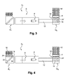
- the figures 2 , 3 and 4 are views of test benches 2 1 , 2 2 and 2 3 according to the invention and in first, second and third embodiments, respectively.
- the test benches 2 1 , 2 2 and 2 3 comprise a test chamber 6 in which the turbojet engine 4 is mounted; a vertical inlet channel 8 1 , 8 2 and 8 3 connected to the chamber 6 upstream of the turbojet engine 4; and a vertical outlet channel 10 1 , 10 2 and 10 3 connected to the chamber 6 downstream of the turbojet engine 4.
- the section of the vertical inlet channels 8 1 , 8 2 and 8 3 and the outlet pipes 10 1 , 10 2 and 10 3 is between 2m 2 and 200 m 2 , preferably between 40m 2 and 70m 2 .
- the input channels 8 1 , 8 2 and 8 3 and output channels 10 1 , 10 2 and 10 3 are in this case square section.
- the test benches 2 1 , 2 2 and 2 3 also comprise a collector tube 12 for the gaseous flow produced by the test downstream of the turbojet engine 4.
- the collector tube 12 is disposed horizontally and comprises at its outlet a diffuser 14 in the vertical outlet channel 10 1 , 10 2 and 10 3 .
- the collector tube 12 is also configured to absorb the noise produced by the test.
- the test benches 2 1 , 2 2 and 2 3 furthermore comprise a wind turbine 18 and 18 'located in the vertical inlet channel 8 1 and 8 3 and / or in the vertical outlet channel 10 2 and 3 .
- the test bench according to the invention may comprise several wind turbines in the vertical input channel and / or in the vertical outlet channel.
- wind turbine is a commonly used term for a wind turbine, or wind turbine, to convert mechanical energy into electrical energy.
- the “wind turbine” can also be understood as a fan for generating an air flow, in this case by transforming electrical energy into mechanical energy.
- the method according to the invention implemented by the test benches 2 1 , 2 2 and 2 3 is that of recovering the kinetic energy of the air flow produced during a test of the turbojet engine 4, the recovery being carried out. by rotating the wind turbine or turbines produced by the air flow, which generates electricity.
- Another method according to the invention and implemented by the test benches 2 1 , 2 2 and 2 3 is that of producing an excess of air flow in the test benches 2 1 , 2 2 and 2 3 , thanks to the wind turbine (s) operating as a fan.
- test bench according to the invention is applicable for test benches 2 1 , 2 2 and 2 3 .
- the figure 2 is a perspective view of a test stand 2 1 according to the invention and in a first embodiment.
- the test stand 2 1 comprises a wind turbine 18 located in the vertical inlet channel 8 1 and converting into mechanical energy the kinetic energy of a portion of the gas flow generated by the turbojet engine test in the bench and passing through the vertical input channel 8 1 . It can be seen that the wind turbine 18 is oriented in a vertical axis, it is precisely located in a bent portion 20 of the test bench 2 1 , portion connecting the vertical inlet channel 8 1 to the chamber 6.
- Deflectors 22 are located in the bend 20 to guide, in the direction of the chamber 6, the flow of fresh air from a vertical axis to a horizontal axis; an arrow is shown in the test stand 2 1 to illustrate the direction of movement of the air.
- the wind turbine 18 is located at the entrance to the bent portion 20 of the test stand 2 1 .
- the vertical input channel 8 1 comprises a noise reduction device 16, in this case acoustic baffles, the wind turbine 18 being situated between the acoustic baffles 16 and the baffles 22.
- vertical input channel 8 1 comprises in this case several rows of acoustic baffles 16.
- the vertical outlet channel 10 1 also comprises acoustic baffles 16 ', a wind turbine can be disposed between the acoustic baffles 16' and the diffuser 14.
- the test stand 2 1 further comprises a water droplet projection device 24 disposed directly upstream of the wind turbine 18, preferably at a distance of less than 1 m, more preferably less than 0.5 m, from said 18.
- This projection device 24 is configured to increase the density of the air flow.
- the density of the air flow can be increased by 10%, preferably by 20%, more preferably by 30%.
- the water is favorably projected in the form of a water mist, the projection being carried out over a portion greater than 50%, preferably greater than 80%, of the section of the vertical inlet channel 8 1 .
- the water flow projected in the vertical inlet channel 8 1 is adjusted so that the relative humidity of the air downstream of the projection device can be greater than 95%, preferably greater than 99.9%. .
- the water projection device 24 is intended to produce a water flow rate of up to 150 kg / s, preferably a water flow rate of between 2 kg / s and 40 kg / s. This measurement is interesting in that the increase in the density of the air mass moving in the test bench increases its kinetic energy. Increasing the kinetic energy of the air is advantageous for the recovery of energy, its high relative humidity is also favorable to the efficiency of the turbojet engine.
- the wind turbine 18 comprises blades 26 with variable orientation, the modification of the orientation of the blades 26 for changing the rotational speed of the wind turbine 18.
- the speed of rotation of the wind turbine is between 50tr / min and 1000tr / min, preferably between 100tr / min and 500tr / min and the air flow at the wind turbine 18 has a speed between 5m / s and 20m / s.
- This measurement is interesting in that the adjustment of the orientation of the blades 26 of the wind turbine 18 makes it possible to establish a rotational speed of the wind turbine adapted for the efficiency of the energy recovery.
- the wind turbine 18 further comprises conversion systems (not shown) of the mechanical energy into electrical energy, which may comprise a control (not shown) determining the electrical power to be converted.
- the wind turbine 18 is configured to recover an electric power of between 1MW and 15MW.
- the figure 3 is a simplified sectional view of a test bench 2 2 according to the invention and in a second embodiment.
- the test stand 2 2 comprises a wind turbine 18 'located in the vertical outlet channel 10 2 downstream of the turbojet engine 4.
- the vertical outlet channel 10 2 comprises in this embodiment a device 15' capable of guiding the engine. flow of the gaseous mixture homogeneously from the vertical outlet channel 2 to the atmosphere. It can be observed that the wind turbine 18 'is disposed between the diffuser 14 and the device 15'; the device 15 'avoids the formation of localized inversions of flow downstream of the wind turbine.
- the vertical outlet channel 10 2 comprises acoustic wall coverings 17 located between the device 15 'for guiding the flow of the gas mixture and the wind turbine 18'.
- the axis of rotation of the wind turbine 18 ' is vertical.
- a water projection device 24 'located upstream of the wind turbine 18' can be observed and making it possible to increase the density of the gaseous mixture as seen in relation to the figure 2 .
- the produced water mist increases the mass flow rate of the gas mixture.
- the gas mixture can favorably reach a relative humidity of 100% downstream of the water projection device 24 '.
- the temperature of the gas mixture at the vertical outlet channel 10 2 is also higher than that at the input of the test bench, it may be greater than 50 ° C. This measure is interesting in that the expansion of the gas mixture, associated with the temperature, increases its speed; the increase in the density of the gas flow added to this increase in the speed is favorable to the increase of the kinetic energy of the gaseous mixture.
- the characteristics of the wind turbine 18 ' are moreover identical to those of the wind turbine seen in connection with the figure 2 , the wind turbine 18 'is able to recover an electrical power of between 1 MW and 15MW.
- the figure 4 is a simplified sectional view of a test stand 2 3 according to the invention and in a third embodiment. It can be seen that a first wind turbine 18 is located in the vertical inlet channel 8 3 as presented in connection with the figure 2 and a second turbine 18 'is situated in the vertical outlet channel 10 3 as presented in relation to the figure 3 .
- the wind turbines 18 and 18 ' comprise water projection devices 24 and 24' as presented in connection with the figures 2 and 3 .
- the vertical inlet channel 8 3 comprises a device 15 capable of guiding the flow of air in a homogeneous manner from the atmosphere in the vertical inlet channel 8 3 . This measure promotes the laminar flow of air in the test stand 2 3 upstream of the wind turbine 18.
- the wind turbine 18 is disposed between the device 15 and the deflectors 22. It can also be seen in the vertical channel 10 3 a device 15 'able to guide the flow of gaseous mixture as well as acoustic wall coverings 17, as presented in connection with the figure 3 .
Landscapes
- Engineering & Computer Science (AREA)
- Chemical & Material Sciences (AREA)
- Combustion & Propulsion (AREA)
- Mechanical Engineering (AREA)
- General Engineering & Computer Science (AREA)
- Physics & Mathematics (AREA)
- General Physics & Mathematics (AREA)
- Wind Motors (AREA)
Abstract
Description
- L'invention a trait à un banc d'essai pour turbomachine. Plus particulièrement l'invention a trait à un banc d'essai pour turbomachine configuré pour la récupération d'énergie générée lors d'un essai.
- Le document de brevet
WO 2012/171105 A1 divulgue un banc d'essai pour turbomachine comprenant un système de valorisation d'énergie. Le système récupère l'énergie cinétique d'un mélange de gaz de combustion et d'air se déplaçant dans le banc d'essai et transforme cette énergie cinétique en électricité au moyen d'une éolienne. La turbomachine est située dans une chambre d'essai et l'éolienne est située dans un tube en aval de la chambre d'essai. Le tube est couramment appelé « tube collecteur » en ce qu'il collecte les gaz de combustion sortant de la turbomachine. La vitesse élevée des gaz de combustion dans le tube permet d'aspirer un minimum d'air ambiant autour de la turbomachine de manière à satisfaire les conditions d'essai requises en termes de flux d'air minimal dans la chambre d'essai. Le tube collecteur joue en quelque sorte un rôle de pompe du mélange gazeux en vue de son expulsion, il évite également des inversions localisées de l'écoulement en aval de la turbomachine. Le tube collecteur peut en particulier être configuré pour absorber les ondes sonores en aval de la turbomachine. L'éolienne comprend des pales à pas variable pour s'adapter aux différentes vitesses de flux du mélange gazeux atteintes selon la taille des turbomachines testées ; elle est connectée à un alternateur/générateur pour générer l'électricité. Cet enseignement est intéressant en ce que l'éolienne positionnée dans le tube collecteur reçoit un flux de mélange de gaz sensiblement laminaire. Par ailleurs, le tube limite la taille de l'éolienne. L'enseignement se limite cependant aux essais de turbomachines pour lesquelles la vitesse et la pression des gaz d'échappements de la turbomachine, modifiés par la présence de l'éolienne dans le tube, garantissent toujours le minimum d'aspiration d'air ambiant de la chambre d'essai nécessaire pour l'essai. Par ailleurs, la position de l'éolienne dans le tube recevant un mélange gazeux de produits de combustion à haute température impose des contraintes de fonctionnement à l'éolienne qui en augmentent le coût. - Le document de brevet
EP 2 336 507 A1 divulgue un banc d'essai pour turbomachine comprenant une turbine destinée à récupérer l'énergie cinétique des gaz d'échappement de la turbomachine. La turbine est disposée entre une chambre d'essai, en amont, dans laquelle est située la turbomachine, et une chambre d'expulsion des gaz d'échappement, en aval. La turbine est configurée pour remplacer la fonction d'un tube collecteur conventionnel qui est généralement d'une longueur importante. En particulier, la turbine est apte à absorber les ondes sonores, par exemple les infrasons. Le rotor de la turbine sur lequel sont montées les pales entrainées en rotation par l'énergie cinétique du flux gazeux, comprend également une hélice fonctionnant en ventilateur de manière à équilibrer les pressions d'air entre la chambre d'essai et la chambre d'expulsion selon les turbomachines testées. Cet enseignement est intéressant en ce que le banc d'essai est sensiblement compact. Il se limite cependant à l'essai de turbomachines pour lesquelles la température des gaz d'échappement ne dépasse pas un seuil critique pour les composants de la turbine. Par ailleurs, la turbine forme un frein à l'écoulement des gaz en aval du moteur, et des inversions localisées de l'écoulement peuvent perturber l'essai des turbomachines. - L'invention a pour objectif de proposer une solution de banc d'essai pour turbomachine palliant au moins un inconvénient de l'état de l'art, en particulier de l'état de l'art susmentionné. Plus particulièrement, l'invention a pour objectif de proposer une solution de banc d'essai pour turbomachine, adaptée pour la récupération d'énergie cinétique du flux d'air généré par l'essai de turbomachines de tailles variées.
- L'invention a pour objet un banc d'essai pour turbomachine axiale, notamment pour turboréacteur, comprenant : une chambre destinée à recevoir la turbomachine ; un canal vertical d'entrée relié à la chambre en amont de la turbomachine ; et un canal vertical de sortie relié à la chambre en aval de la turbomachine ; au moins une éolienne qui est apte à convertir l'énergie cinétique d'une partie du flux gazeux généré par la turbomachine en énergie mécanique, et qui comprend au moins un ou plusieurs systèmes de conversion de l'énergie mécanique en énergie électrique; remarquable en ce que l'éolienne ou au moins une des éoliennes est située dans le canal vertical d'entrée et/ou dans le canal vertical de sortie. Par « éolienne » on entend « turbine éolienne » ou « aérogénérateur ».
- Selon un mode avantageux de l'invention, le banc d'essai comprend au moins un dispositif de projection de gouttelettes d'eau en amont de l'éolienne ou d'une des éoliennes.
- Selon un mode avantageux de l'invention, le ou au moins un des dispositifs de projection est disposé directement en amont de l'éolienne correspondante, préférentiellement à une distance de moins de 1m, plus préférentiellement moins de 0.5m, de ladite éolienne.
- Selon un mode avantageux de l'invention, le ou chacun des dispositifs de projection est configuré pour augmenter la densité du flux gazeux de 10%, préférentiellement de 20%, plus préférentiellement de 30%.
- Avantageusement, l'augmentation de la densité du flux gazeux augmente le débit massique dans le banc d'essai.
- Selon un mode avantageux de l'invention, l'éolienne ou au moins une des éoliennes présente un axe de rotation vertical.
- Selon un mode avantageux de l'invention, la section du canal vertical d'entrée et/ou du canal vertical de sortie, à hauteur de l'éolienne, est comprise entre 2m2 et 200 m2, préférentiellement entre 40m2 et 70m2.
- Selon un mode avantageux de l'invention, le banc d'essai comprend une portion coudée reliant le canal vertical d'entrée à la chambre, ledit coude comprenant des déflecteurs pour guider le flux d'air frais depuis une direction verticale vers une direction horizontale, la ou au moins une des éoliennes étant disposée à l'entrée dudit coude.
- Selon un mode avantageux de l'invention, le canal vertical d'entrée comprend, à son entrée, un dispositif apte à guider l'écoulement d'air de manière homogène depuis l'atmosphère dans ledit canal d'entrée, la ou au moins une des éoliennes étant disposée entre les déflecteurs et ledit dispositif d'écoulement.
- Selon un mode avantageux de l'invention, la ou au moins une des éoliennes comprend des pales à orientation variable.
- Selon un mode avantageux de l'invention, la ou au moins une des éoliennes comprend des systèmes de conversion de l'énergie mécanique en énergie électrique.
- Selon un mode avantageux de l'invention, au moins un système de conversion de l'énergie mécanique en énergie électrique comprend une commande apte à déterminer la puissance électrique à convertir.
- Selon un mode avantageux de l'invention, le banc d'essai comprend un tube collecteur du flux gazeux à la sortie de la turbomachine, ledit tube collecteur étant disposé horizontalement et comprenant, à sa sortie, un diffuseur dans le canal vertical de sortie.
- Selon un mode avantageux de l'invention, le canal vertical de sortie comprend, à sa sortie, un dispositif de réduction de bruit, l'éolienne ou une des éoliennes étant disposée entre le diffuseur du tube collecteur et le dispositif de réduction de bruit.
- Selon un mode avantageux de l'invention, le dispositif de réduction de bruit comprend des baffles acoustiques et/ou des revêtements acoustiques muraux.
- Selon un mode avantageux de l'invention, le canal vertical de sortie comprend des revêtements acoustiques muraux et un dispositif de guidage de l'écoulement de mélange gazeux, lesdits revêtements acoustiques étant situés entre ledit dispositif de guidage et l'éolienne ou une des éoliennes.
- Selon un mode avantageux de l'invention, le banc d'essai comprend plusieurs éoliennes dans le canal vertical d'entrée et/ou le canal vertical de sortie.
- L'invention a également pour objet un procédé de récupération d'énergie d'un banc d'essai pour turbomachine axiale, notamment pour turboréacteur, remarquable en ce que le banc d'essai est conforme à l'invention, le procédé comprenant la génération d'un flux d'air par la turbomachine axiale et la rotation de la ou d'au moins une des éoliennes du banc d'essai provoquée par ledit flux d'air, la rotation de ladite ou d'au moins l'une desdites éoliennes générant de l'électricité.
- Le banc d'essai est avantageusement configuré pour tester des turbomachines de poussée comprise entre 1 T et 70T.
- Selon un mode avantageux de l'invention, le banc d'essai est configuré pour générer un débit massique d'air dans la chambre compris entre 0,1kg/s et 3000kg/s, préférentiellement entre 200kg/s et 1200kg/s.
- Selon un mode avantageux de l'invention, la vitesse de rotation de la ou d'au moins une des éoliennes est comprise entre 50tr/min et 1000tr/min, préférentiellement entre 100tr/min et 500tr/min et le flux d'air au niveau de ladite ou desdites éoliennes présente une vitesse comprise entre 5m/s et 20m/s.
- Selon un mode avantageux de l'invention, le ou au moins un des dispositifs de projection de gouttelettes d'eau est configuré de sorte à ce que l'humidité relative « e » de l'air en aval dudit ou desdits dispositifs est comprise entre 95% et 100%, préférentiellement entre 99,9% et 100%.
- Selon un mode avantageux de l'invention, l'eau est projetée dans au moins un des canaux verticaux d'entrée et de sortie sous la forme d'un brouillard d'eau et sur une portion supérieure à 50%, préférentiellement supérieure à 80% de la section du ou des canaux.
- Selon un mode avantageux de l'invention, le ou au moins un des dispositifs de projection d'eau est destiné à produire un débit d'eau jusqu'à 150kg/s, préférentiellement un débit d'eau compris entre 2kg/s et 40kg/s.
- Selon un mode avantageux de l'invention, la ou au moins une des éoliennes est apte à produire une puissance électrique comprise entre 1MW et 15MW, ou comprise entre 0,1MW et 15MW.
- L'invention a également pour objet un procédé de fonctionnement d'un banc d'essai pour turbomachine axiale, notamment pour turboréacteur, remarquable en ce que le banc d'essai est conforme à l'invention, la ou au moins une des éoliennes étant configurée pour fonctionner en ventilateur de manière à augmenter le flux d'air dans le banc d'essai.
- Les mesures de l'invention sont intéressantes en ce que le banc d'essai pour turbomachine axiale est apte à récupérer en électricité l'énergie cinétique du flux d'air généré dans le banc par l'essai de modèles variés de turbomachines. En effet, l'éolienne positionnée dans un canal vertical à l'entrée et/ou à la sortie du banc d'essai est détachée des zones autour de la turbomachine, notamment en aval et en périphérie, zones dans lesquelles les vitesses de déplacement d'air sont élevées et leur modification critique à la qualité des conditions de l'essai. En outre, la vitesse de l'air dans les canaux verticaux est plus faible relativement à celle dans les zones autour de la turbomachine, et les éoliennes, configurées pour entrer en rotation dans de tels conditions de vitesse d'air, sont aptes à générer une puissance électrique adaptée. Par ailleurs, le flux d'air est sensiblement laminaire dans les canaux verticaux, ce qui est favorable au rendement de la récupération d'énergie.
- D'autres caractéristiques et avantages de la présente invention seront mieux compris à l'aide de la description et des dessins parmi lesquels :
- La
figure 1 est une vue de l'intérieur d'un banc d'essai conforme à l'invention dans lequel est monté une turbomachine axiale ; - La
figure 2 est une vue en perspective du banc d'essai de lafigure 1 dans un premier mode de réalisation ; - La
figure 3 est une vue en coupe simplifiée d'un banc d'essai conforme à l'invention et dans un deuxième mode de réalisation ; - La
figure 4 est une vue en coupe simplifiée d'un banc d'essai conforme à l'invention et dans un troisième mode de réalisation ; - La
figure 1 est une vue de l'intérieur d'un banc d'essai 2 conforme à l'invention, banc d'essai dans lequel est monté une turbomachine axiale 4. La turbomachine est en l'occurrence un turboréacteur d'avion. Le turboréacteur 4 est apte, selon le modèle, à produire une poussée de 1T à 70T. Son passage au banc d'essai 2 est effectué dans des circonstances variées : Le turboréacteur 4 peut passer au banc d'essai dans le cadre d'un nouveau développement ou pour un contrôle qualité après fabrication ou suite à une maintenance. Pour ces différents types d'essais, le turboréacteur 4 génère un déplacement d'air dont la masse et la vitesse produisent de l'énergie cinétique. Une partie de cette énergie cinétique est destinée, dans le cadre de l'invention, à être récupérée. Pour l'essai de tels turboréacteurs 4, le banc d'essai 2 est configuré pour générer un débit massique d'air compris entre 0,1 kg/s et 3000kg/s, préférentiellement entre 200kg/s et 1200kg/s. - Les
figures 2 ,3 et 4 sont des vues de bancs d'essai 21, 22 et 23 conformes à l'invention et dans des premier, deuxième, et troisième modes de réalisation, respectivement. Les bancs d'essai 21, 22 et 23 comprennent une chambre d'essai 6 dans laquelle est monté le turboréacteur 4 ; un canal vertical d'entrée 81, 82 et 83 relié à la chambre 6 en amont du turboréacteur 4 ; et un canal vertical de sortie 101, 102 et 103 relié à la chambre 6 en aval du turboréacteur 4. La section des canaux verticaux d'entrée 81, 82 et 83 et de sortie 101, 102 et 103 est comprise entre 2m2 et 200 m2, préférentiellement entre 40m2 et 70m2. Les canaux d'entrée 81, 82 et 83 et de sortie 101, 102 et 103 sont en l'occurrence de section carrée. Les bancs d'essai 21, 22 et 23 comprennent également un tube collecteur 12 du flux gazeux produit par l'essai en aval du turboréacteur 4. Le tube collecteur 12 est disposé horizontalement et comprend à sa sortie un diffuseur 14 dans le canal vertical de sortie 101, 102 et 103. Le tube collecteur 12 est par ailleurs configuré pour absorber le bruit produit par l'essai. Les bancs d'essai 21, 22 et 23 comprennent en outre une éolienne 18 et 18' située dans le canal vertical d'entrée 81 et 83 et/ou dans le canal vertical de sortie 102 et 103. Dans un mode alternatif de réalisation (non représenté) le banc d'essai conforme à l'invention peut comprendre plusieurs éoliennes dans le canal vertical d'entrée et/ou dans le canal vertical de sortie. - Le terme d' « éolienne » est un terme couramment utilisé pour désigner une turbine éolienne, ou aérogénérateur, destiné à convertir de l'énergie mécanique en énergie électrique. L'« éolienne » peut s'entendre également comme un ventilateur destiné à générer un flux d'air, en l'occurrence par transformation d'une énergie électrique en énergie mécanique.
- Le procédé conforme à l'invention mis en oeuvre par les bancs d'essai 21, 22 et 23 est celui de récupérer l'énergie cinétique du flux d'air produit lors d'un essai du turboréacteur 4, la récupération se faisant par la rotation de la ou des éoliennes produite par le flux d'air, ce qui génère de l'électricité. Un autre procédé conforme à l'invention et mis en oeuvre par les bancs d'essai 21, 22 et 23 est celui de produire un surplus de flux d'air dans les bancs d'essai 21, 22 et 23, grâce à la ou aux éoliennes fonctionnant en ventilateur.
- La configuration du banc d'essai conforme à l'invention et présenté en relation avec la
figure 1 est applicable pour les bancs d'essai 21, 22 et 23. - La
figure 2 est une vue en perspective d'un banc d'essai 21 conforme à l'invention et dans un premier mode de réalisation. Le banc d'essai 21 comprend une éolienne 18 située dans le canal vertical d'entrée 81 et convertissant en énergie mécanique l'énergie cinétique d'une partie du flux gazeux généré par l'essai du turboréacteur dans le banc et traversant le canal vertical d'entrée 81. On peut observer que l'éolienne 18 est orientée dans un axe vertical, elle est précisément située dans une portion coudée 20 du banc d'essai 21, portion reliant le canal vertical d'entrée 81 à la chambre 6. Des déflecteurs 22 sont situés dans le coude 20 pour guider, en direction de la chambre 6, le flux d'air frais depuis un axe vertical vers un axe horizontal ; une flèche est représentée dans le banc d'essai 21 pour illustrer le sens de déplacement de l'air. L'éolienne 18 est située à l'entrée de la portion coudée 20 du banc d'essai 21. Dans le mode de réalisation ici présenté, le canal vertical d'entrée 81 comprend un dispositif de réduction de bruit 16, en l'occurrence des baffles acoustiques, l'éolienne 18 étant située entre les baffles acoustiques 16 et les déflecteurs 22. Le canal vertical d'entrée 81 comprend en l'occurrence plusieurs rangées de baffles acoustiques 16. Le canal vertical de sortie 101 comprend également des baffles acoustiques 16', une éolienne peut être disposée entre les baffles acoustiques 16' et le diffuseur 14. Le banc d'essai 21 comprend, en outre, un dispositif de projection 24 de gouttelettes d'eau disposé directement en amont de l'éolienne 18 préférentiellement à une distance de moins de 1m, plus préférentiellement moins de 0,5m, de ladite éolienne 18. Ce dispositif de projection 24 est configuré pour augmenter la densité du flux d'air. La densité du flux d'air peut être augmentée de 10%, préférentiellement de 20%, plus préférentiellement de 30%. L'eau est favorablement projetée sous forme d'un brouillard d'eau, la projection étant réalisée sur une portion supérieure à 50%, préférentiellement supérieure à 80%, de la section du canal vertical d'entrée 81. Le débit d'eau projetée dans le canal vertical d'entrée 81 est réglé de sorte à ce que l'humidité relative de l'air en aval du dispositif de projection puisse être supérieure à 95%, préférentiellement supérieure à 99,9%. Le dispositif de projection d'eau 24 est destiné à produire un débit d'eau jusqu'à 150kg/s, préférentiellement un débit d'eau compris entre 2kg/s et 40kg/s. Cette mesure est intéressante en ce que l'augmentation de la densité de la masse d'air se déplaçant dans le banc d'essai augmente son énergie cinétique. L'augmentation de l'énergie cinétique de l'air est avantageuse pour la récupération d'énergie, son humidité relative élevée est par ailleurs favorable au rendement du turboréacteur. - L'éolienne 18 comprend des pales 26 à orientation variable, la modification de l'orientation des pales 26 permettant de modifier la vitesse de rotation de l'éolienne 18. La vitesse de rotation de l'éolienne est comprise entre 50tr/min et 1000tr/min, préférentiellement entre 100tr/min et 500tr/min et le flux d'air au niveau de l'éolienne 18 présente une vitesse comprise entre 5m/s et 20m/s. Cette mesure est intéressante en ce que le réglage de l'orientation des pales 26 de l'éolienne 18 permet d'établir une vitesse de rotation de l'éolienne adaptée pour le rendement de la récupération d'énergie. L'éolienne 18 comprend, en outre, des systèmes de conversion (non représentés) de l'énergie mécanique en énergie électrique, ceux-ci pouvant comprendre une commande (non représentée) déterminant la puissance électrique à convertir. L'éolienne 18 est configurée pour récupérer une puissance électrique comprise entre 1MW et 15MW.
- La
figure 3 est une vue en coupe simplifiée d'un banc d'essai 22 conforme à l'invention et dans un deuxième mode de réalisation. A la différence du premier mode de réalisation présenté en relation avec lafigure 2 , le banc d'essai 22 comprend une éolienne 18' située dans le canal vertical de sortie 102 en aval du turboréacteur 4. Le canal vertical de sortie 102 comprend dans ce mode de réalisation un dispositif 15' apte à guider l'écoulement du mélange gazeux de manière homogène depuis le canal vertical de sortie 102 vers l'atmosphère. On peut observer que l'éolienne 18' est disposée entre le diffuseur 14 et le dispositif 15' ; le dispositif 15' évite la formation d'inversions localisées d'écoulement en aval de l'éolienne. Cette mesure est intéressante pour réduire la sensibilité du banc d'essai 22, par exemple à un vent extérieur, et favoriser le rendement de la récupération d'énergie. En outre, le canal vertical de sortie 102 comprend des revêtements acoustiques muraux 17 situés entre le dispositif 15' de guidage de l'écoulement du mélange gazeux et l'éolienne 18'. L'axe de rotation de l'éolienne 18' est vertical. On peut observer un dispositif de projection d'eau 24' situé en amont de l'éolienne 18' et permettant d'augmenter la densité du mélange gazeux comme vue en relation avec lafigure 2 . Le brouillard d'eau produit augmente le débit massique du mélange gazeux. Le mélange gazeux peut favorablement atteindre une humidité relative de 100% en aval du dispositif de projection d'eau 24'. La température du mélange gazeux au niveau du canal vertical de sortie 102 est par ailleurs plus élevée que celle en entrée du banc d'essai, elle peut être supérieure à 50°C. Cette mesure est intéressante en ce que la dilatation du mélange gazeux, associée à la température, augmente sa vitesse ; l'augmentation de la densité du flux gazeux ajoutée à cette augmentation de la vitesse est favorable à l'augmentation de l'énergie cinétique du mélange gazeux. Les caractéristiques de l'éolienne 18' sont par ailleurs identiques à celles de l'éolienne vues en relation avec lafigure 2 , l'éolienne 18' est apte à récupérer une puissance électrique comprise entre 1 MW et 15MW. - La
figure 4 est une vue en coupe simplifiée d'un banc d'essai 23 conforme à l'invention et dans un troisième mode de réalisation. On peut observer qu'une première éolienne 18 est située dans le canal vertical d'entrée 83 comme présenté en relation avec lafigure 2 et qu'une deuxième éolienne 18' est située dans le canal vertical de sortie 103 comme présenté en relation avec lafigure 3 . Les éoliennes 18 et 18' comprennent des dispositifs de projection d'eau 24 et 24' comme présenté en relation avec lesfigures 2 et3 . On peut observer que le canal vertical d'entrée 83 comprend un dispositif 15 apte à guider l'écoulement d'air de manière homogène de l'atmosphère dans le canal vertical d'entrée 83. Cette mesure favorise l'écoulement laminaire de l'air dans le banc d'essai 23 en amont de l'éolienne 18. L'éolienne 18 est disposée entre le dispositif 15 et les déflecteurs 22. On peut également voir dans le canal vertical de sortie 103 un dispositif 15' apte à guider l'écoulement de mélange gazeux ainsi que des revêtements acoustiques muraux 17, comme présenté en relation avec lafigure 3 .
Claims (15)
- Banc d'essai (21 ; 22 ; 23) pour turbomachine axiale (4), notamment pour turboréacteur, comprenant :- une chambre (6) destinée à recevoir la turbomachine (4) ;- un canal vertical d'entrée (81 ; 82 ; 83) relié à la chambre (6) en amont de la turbomachine (4) ; et- un canal vertical de sortie (101 ; 102 ; 103) relié à la chambre (6) en aval de la turbomachine (4) ;- au moins une éolienne (18; 18') qui est apte à convertir l'énergie cinétique d'une partie du flux gazeux généré par la turbomachine (4) en énergie mécanique, et qui comprend au moins un ou plusieurs systèmes de conversion de l'énergie mécanique en énergie électrique ;
caractérisé en ce que l'éolienne (18; 18') ou au moins une des éoliennes (18 ; 18') est située dans le canal vertical d'entrée (81 ; 82 ; 83) et/ou dans le canal vertical de sortie (101 ; 102 ; 103). - Banc d'essai (21 ; 22 ; 23) selon la revendication 1, caractérisé en ce qu'il comprend au moins un dispositif de projection de gouttelettes d'eau (24 ; 24') en amont de l'éolienne (18 ; 18') ou d'une des éoliennes.
- Banc d'essai (21 ; 22 ; 23) selon la revendication 2, caractérisé en ce que le ou au moins un des dispositifs de projection (24 ; 24') est disposé directement en amont de l'éolienne (18; 18') correspondante, préférentiellement à une distance de moins de 1m, plus préférentiellement moins de 0.5m, de ladite éolienne.
- Banc d'essai (21 ; 22 ; 23) selon l'une des revendications 2 et 3, caractérisé en ce que le ou chacun des dispositifs de projection (24 ; 24') est configuré pour augmenter la densité du flux gazeux de 10%, préférentiellement de 20%, plus préférentiellement de 30%.
- Banc d'essai (21 ; 22 ; 23) selon l'une des revendications 1 à 4, caractérisé en ce que l'éolienne (18 ; 18') ou au moins une des éoliennes (18 ; 18') présente un axe de rotation vertical.
- Banc d'essai (21 ; 22 ; 23) selon l'une des revendications 1 à 5, caractérisé en ce que la section du canal vertical d'entrée (81 ; 82 ; 83) et/ou du canal vertical de sortie (101 ; 102 ; 103), à hauteur de l'éolienne (18 ; 18'), est comprise entre 2 et 200m2, préférentiellement entre 40m2 et 70m2.
- Banc d'essai (21 ; 23) selon l'une des revendications 1 à 6, caractérisé en ce qu'il comprend une portion coudée (20) reliant le canal vertical d'entrée (81 ; 83) à la chambre (6), ledit coude comprenant des déflecteurs (22) pour guider le flux d'air frais depuis une direction verticale vers une direction horizontale, la ou au moins une des éoliennes (18) étant disposée à l'entrée dudit coude (20).
- Banc d'essai (21 ; 22 ; 23) selon l'une des revendications 1 à 7, caractérisé en ce que la ou au moins une des éoliennes (18 ; 18') comprend des pales (26) à orientation variable.
- Banc d'essai (21 ; 22 ; 23) selon l'une des revendications 1 à 8, caractérisé en ce que la ou au moins une des éoliennes (18 ; 18') est apte à produire une puissance électrique comprise entre 1MW et 15MW, ou comprise entre 0,1 MW et 15MW.
- Banc d'essai (21 ; 22 ; 23) selon l'une des revendications 1 à 9, caractérisé en ce qu'il comprend un tube collecteur (12) du flux gazeux à la sortie de la turbomachine (4), ledit tube étant disposé horizontalement et comprenant, à sa sortie, un diffuseur (14) dans le canal vertical de sortie (101 ; 102 ; 103).
- Banc d'essai (21 ; 22 ; 23) selon la revendication 10, caractérisé en ce que le canal vertical de sortie (101 ; 102 ; 103) comprend, à sa sortie, un dispositif de réduction de bruit (16' ; 17), l'éolienne (18') ou une des éoliennes (18') étant disposée entre le diffuseur (14) du tube collecteur (12) et le dispositif de réduction de bruit (16' ; 17).
- Procédé de récupération d'énergie d'un banc d'essai (21 ; 22 ; 23) pour turbomachine axiale (4), notamment pour turboréacteur, caractérisé en ce que le banc d'essai (21 ; 22 ; 23) est conforme à l'une des revendications 1 à 11, le procédé comprenant la génération d'un flux d'air par la turbomachine axiale (4) et la rotation de la ou d'au moins une des éoliennes (18 ; 18') du banc d'essai provoquée par ledit flux d'air, la rotation de ladite ou d'au moins l'une desdites éoliennes (18 ; 18') générant de l'électricité.
- Procédé de récupération d'énergie selon la revendication 12, caractérisé en ce que la vitesse de rotation de la ou d'au moins une des éoliennes (18 ; 18') est comprise entre 50tr/min et 1000 tr/min, préférentiellement entre 100tr/min et 500tr/min et le flux d'air au niveau de ladite ou desdites éoliennes (18 ; 18') présente une vitesse comprise entre 5m/s et 20m/s.
- Procédé de récupération d'énergie selon l'une des revendications 12 et 13, caractérisé en ce que le banc d'essai (21 ; 22 ; 23) est conforme à l'une des revendications 2 à 4, le ou au moins un des dispositifs de projection de gouttelettes d'eau (24 ; 24') est configuré de sorte à ce que l'humidité relative (e) de l'air en aval dudit ou desdits dispositifs est compris entre 95% et 100%, préférentiellement entre 99,9% et 100%.
- Procédé de fonctionnement d'un banc d'essai (21 ; 22 ; 23) pour turbomachine axiale (4), notamment pour turboréacteur, caractérisé en ce que le banc d'essai est conforme à l'une des revendications 1 à 11, la ou au moins une des éoliennes (18 ; 18') étant configurée pour fonctionner en ventilateur de manière à augmenter le flux d'air dans ledit banc d'essai.
Priority Applications (1)
| Application Number | Priority Date | Filing Date | Title |
|---|---|---|---|
| PL15194001T PL3021102T3 (pl) | 2014-11-17 | 2015-11-11 | Stanowisko badawcze do testowania osiowej maszyny wirowej z pionowym silnikiem wiatrowym |
Applications Claiming Priority (1)
| Application Number | Priority Date | Filing Date | Title |
|---|---|---|---|
| BE2014/0822A BE1022512B1 (fr) | 2014-11-17 | 2014-11-17 | Banc d'essai pour turbomachine axiale avec eolienne verticale |
Publications (2)
| Publication Number | Publication Date |
|---|---|
| EP3021102A1 true EP3021102A1 (fr) | 2016-05-18 |
| EP3021102B1 EP3021102B1 (fr) | 2019-05-15 |
Family
ID=52462092
Family Applications (1)
| Application Number | Title | Priority Date | Filing Date |
|---|---|---|---|
| EP15194001.2A Active EP3021102B1 (fr) | 2014-11-17 | 2015-11-11 | Banc d'essai pour turbomachine axiale avec eolienne verticale |
Country Status (5)
| Country | Link |
|---|---|
| US (1) | US10107717B2 (fr) |
| EP (1) | EP3021102B1 (fr) |
| BE (1) | BE1022512B1 (fr) |
| ES (1) | ES2734234T3 (fr) |
| PL (1) | PL3021102T3 (fr) |
Cited By (10)
| Publication number | Priority date | Publication date | Assignee | Title |
|---|---|---|---|---|
| EP3290897A1 (fr) * | 2016-09-05 | 2018-03-07 | Safran Aero Boosters SA | Banc d'essai de turbomachine avec contrôle actif du bruit |
| CN110621858A (zh) * | 2017-04-03 | 2019-12-27 | 赛峰直升机发动机公司 | 检查装有两个涡轮发动机的飞机的涡轮发动机的最大可用功率的方法 |
| WO2021009226A1 (fr) * | 2019-07-16 | 2021-01-21 | Safran Aero Boosters | Banc d'essai de turbomachines dépollué |
| FR3102243A1 (fr) * | 2019-10-16 | 2021-04-23 | Safran Aircraft Engines | Banc d’essai auto alimenté en électricité |
| WO2021122448A1 (fr) | 2019-12-19 | 2021-06-24 | Safran Aero Boosters | Methode et systeme d'essai en maintenance de turbomachine |
| CN114326578A (zh) * | 2022-03-10 | 2022-04-12 | 东方电气风电股份有限公司 | 变桨加载柜及控制系统 |
| CN114810352A (zh) * | 2022-07-01 | 2022-07-29 | 华能太原东山燃机热电有限责任公司 | 一种用于燃机试验台的进气装置 |
| BE1028992B1 (fr) * | 2021-01-05 | 2022-08-10 | Safran Aero Boosters | Système de dépollution d’air et procédé de dépollution d’air |
| WO2024209157A1 (fr) | 2023-04-04 | 2024-10-10 | Safran Aircraft Engines | Conduit d'échappement d'un banc d'essai de turbine avec double tube |
| FR3151626A1 (fr) * | 2023-07-26 | 2025-01-31 | Safran Aircraft Engines | Module de soufflante pour un banc d’essai de turbomachine d’aeronef |
Families Citing this family (6)
| Publication number | Priority date | Publication date | Assignee | Title |
|---|---|---|---|---|
| AU2015342726B2 (en) * | 2014-11-06 | 2020-04-02 | Windbidco Pty Ltd | Improved apparatus for sounding the atmosphere and method |
| US10319414B2 (en) * | 2016-09-27 | 2019-06-11 | Seagate Technology Llc | Data storage enclosure with acoustic baffle |
| DE102017210073A1 (de) | 2017-06-14 | 2018-12-20 | Horsch Leeb Application Systems Gmbh | Landwirtschaftliche maschine mit reifendruckregelanlage |
| EP3651304B1 (fr) * | 2018-11-07 | 2021-04-07 | Siemens Gamesa Renewable Energy Innovation & Technology, S.L. | Procédé de réalisation d'une procédure de test d'un système d'alimentation électrique pour éolienne et système d'alimentation électrique |
| CN116104336B (zh) * | 2023-02-03 | 2026-04-17 | 中国航发湖南动力机械研究所 | 一种涡桨发动机试车间 |
| CN119018367B (zh) * | 2024-10-31 | 2025-01-24 | 常州辉天智能科技有限公司 | 一种用于氢动力无人机的动力测试装置 |
Citations (3)
| Publication number | Priority date | Publication date | Assignee | Title |
|---|---|---|---|---|
| JPH1019737A (ja) * | 1996-07-04 | 1998-01-23 | Kobe Steel Ltd | ジェットエンジンテストセル |
| EP2336507A1 (fr) | 2009-12-16 | 2011-06-22 | MDS Aero support corporation | Désaccordeur de turbine pour récupérer l'énergie cinétique de gaz d'échappement de moteurs à turbine à gaz |
| WO2012171105A1 (fr) | 2011-06-15 | 2012-12-20 | C.E.L. Energy Recuperation Inc. | Chambre d'essai pour moteur d'aéronef comprenant un système de récupération d'énergie et procédé de récupération de l'énergie provenant du moteur d'aéronef |
Family Cites Families (14)
| Publication number | Priority date | Publication date | Assignee | Title |
|---|---|---|---|---|
| US6717282B1 (en) * | 2002-07-03 | 2004-04-06 | William J. Maxwell | Combined motor and generator dynamometer system |
| US6952058B2 (en) * | 2003-02-20 | 2005-10-04 | Wecs, Inc. | Wind energy conversion system |
| JP3580810B1 (ja) * | 2004-05-27 | 2004-10-27 | 川崎重工業株式会社 | 超低周波音用吸音装置 |
| GB2438431B (en) * | 2006-05-25 | 2008-08-20 | Rolls Royce Plc | Thrust correction |
| US20120152007A1 (en) * | 2007-01-12 | 2012-06-21 | Richard Holmes | Testing performance of a material for use in a jet engine |
| US8454313B2 (en) * | 2009-08-14 | 2013-06-04 | Benjamin T. Elkin | Independent variable blade pitch and geometry wind turbine |
| US20160251964A1 (en) * | 2009-10-26 | 2016-09-01 | Luis Indefonso Solorzano | Apparatus and methods for energy conversion |
| US8834093B2 (en) * | 2009-11-20 | 2014-09-16 | Peter J. Cucci | System and method for collecting, augmenting and converting wind power |
| US20110318167A1 (en) * | 2010-06-23 | 2011-12-29 | Miller R Scott | Crossflow wind turbine |
| US9080551B2 (en) * | 2012-06-26 | 2015-07-14 | Alexander Jay Yudkovitz | System for generating electrical powerfrom aircraft exhaust |
| US8941256B1 (en) * | 2012-10-01 | 2015-01-27 | Amazon Technologies, Inc. | Energy reclamation from air-moving systems |
| US10208677B2 (en) * | 2012-12-31 | 2019-02-19 | General Electric Company | Gas turbine load control system |
| FR3008185B1 (fr) * | 2013-07-03 | 2017-02-10 | Snecma | Insert comprenant une surface externe faisant partie d'au moins un profil aerodynamique d'une aube de test de turbomachine |
| EP3069016A1 (fr) * | 2013-11-15 | 2016-09-21 | University Of Washington Through Its Center For Commercialization | Systèmes de récupération d'énergie pour ventilation par aspiration et appareils et procédés associés |
-
2014
- 2014-11-17 BE BE2014/0822A patent/BE1022512B1/fr not_active IP Right Cessation
-
2015
- 2015-11-11 EP EP15194001.2A patent/EP3021102B1/fr active Active
- 2015-11-11 ES ES15194001T patent/ES2734234T3/es active Active
- 2015-11-11 PL PL15194001T patent/PL3021102T3/pl unknown
- 2015-11-17 US US14/943,556 patent/US10107717B2/en active Active
Patent Citations (3)
| Publication number | Priority date | Publication date | Assignee | Title |
|---|---|---|---|---|
| JPH1019737A (ja) * | 1996-07-04 | 1998-01-23 | Kobe Steel Ltd | ジェットエンジンテストセル |
| EP2336507A1 (fr) | 2009-12-16 | 2011-06-22 | MDS Aero support corporation | Désaccordeur de turbine pour récupérer l'énergie cinétique de gaz d'échappement de moteurs à turbine à gaz |
| WO2012171105A1 (fr) | 2011-06-15 | 2012-12-20 | C.E.L. Energy Recuperation Inc. | Chambre d'essai pour moteur d'aéronef comprenant un système de récupération d'énergie et procédé de récupération de l'énergie provenant du moteur d'aéronef |
Cited By (16)
| Publication number | Priority date | Publication date | Assignee | Title |
|---|---|---|---|---|
| EP3290897A1 (fr) * | 2016-09-05 | 2018-03-07 | Safran Aero Boosters SA | Banc d'essai de turbomachine avec contrôle actif du bruit |
| CN107796630A (zh) * | 2016-09-05 | 2018-03-13 | 赛峰航空助推器股份有限公司 | 具有有源噪声控制的涡轮机测试台 |
| CN110621858A (zh) * | 2017-04-03 | 2019-12-27 | 赛峰直升机发动机公司 | 检查装有两个涡轮发动机的飞机的涡轮发动机的最大可用功率的方法 |
| CN110621858B (zh) * | 2017-04-03 | 2022-02-08 | 赛峰直升机发动机公司 | 检查装有两个涡轮发动机的飞机的涡轮发动机的最大可用功率的方法 |
| BE1027431B1 (fr) * | 2019-07-16 | 2021-02-15 | Safran Aero Boosters Sa | Banc d'essai de turbomachines dépollué |
| WO2021009226A1 (fr) * | 2019-07-16 | 2021-01-21 | Safran Aero Boosters | Banc d'essai de turbomachines dépollué |
| CN114144575A (zh) * | 2019-07-16 | 2022-03-04 | 赛峰航空助推器有限公司 | 经净化的涡轮机测试台 |
| FR3102243A1 (fr) * | 2019-10-16 | 2021-04-23 | Safran Aircraft Engines | Banc d’essai auto alimenté en électricité |
| WO2021122448A1 (fr) | 2019-12-19 | 2021-06-24 | Safran Aero Boosters | Methode et systeme d'essai en maintenance de turbomachine |
| BE1027893B1 (fr) * | 2019-12-19 | 2021-07-27 | Safran Aero Boosters Sa | Méthode et système d’essai en maintenance de turbomachine |
| BE1028992B1 (fr) * | 2021-01-05 | 2022-08-10 | Safran Aero Boosters | Système de dépollution d’air et procédé de dépollution d’air |
| CN114326578A (zh) * | 2022-03-10 | 2022-04-12 | 东方电气风电股份有限公司 | 变桨加载柜及控制系统 |
| CN114810352A (zh) * | 2022-07-01 | 2022-07-29 | 华能太原东山燃机热电有限责任公司 | 一种用于燃机试验台的进气装置 |
| WO2024209157A1 (fr) | 2023-04-04 | 2024-10-10 | Safran Aircraft Engines | Conduit d'échappement d'un banc d'essai de turbine avec double tube |
| FR3147588A1 (fr) | 2023-04-04 | 2024-10-11 | Safran Aircraft Engines | Conduit d’échappement d’un banc d’essai de turbine avec double tube |
| FR3151626A1 (fr) * | 2023-07-26 | 2025-01-31 | Safran Aircraft Engines | Module de soufflante pour un banc d’essai de turbomachine d’aeronef |
Also Published As
| Publication number | Publication date |
|---|---|
| US10107717B2 (en) | 2018-10-23 |
| EP3021102B1 (fr) | 2019-05-15 |
| PL3021102T3 (pl) | 2019-11-29 |
| US20160139001A1 (en) | 2016-05-19 |
| BE1022512B1 (fr) | 2016-05-18 |
| ES2734234T3 (es) | 2019-12-04 |
Similar Documents
| Publication | Publication Date | Title |
|---|---|---|
| EP3021102B1 (fr) | Banc d'essai pour turbomachine axiale avec eolienne verticale | |
| FR3070448B1 (fr) | Aube de redresseur de soufflante de turbomachine, ensemble de turbomachine comprenant une telle aube et turbomachine equipee de ladite aube ou dudit ensemble | |
| EP3006679B1 (fr) | Carter externe de turbomachine axiale et procédé de commande d'un dispositif d'étanchéité de carter externe de turbomachine axiale | |
| EP3693609B1 (fr) | Mesure de pression totale et température totale dans une turbomachine | |
| CN103016380B (zh) | 汽车发动机冷却风扇叶顶间隙区域的性能确定方法 | |
| KR20080023190A (ko) | 에너지 추출 시스템의 효율을 향상시키는 장치 | |
| EP3290897A1 (fr) | Banc d'essai de turbomachine avec contrôle actif du bruit | |
| EP2878774A1 (fr) | Turbomachine comportant des moyens de support d'au moins un équipement | |
| US20100133849A1 (en) | Power generating skin structure and power generation system therefor | |
| FR3120942A1 (fr) | Banc d’essai de turbomachine comportant un dispositif d’admission d’un polluant | |
| WO1981000286A1 (fr) | Turbine eolienne | |
| US20130101398A1 (en) | Impulse wind machine | |
| FR2612250A1 (fr) | Dispositif d'echappement d'une turbine a gaz, comportant un diffuseur de jets | |
| FR3118792A1 (fr) | Module pour une turbomachine d’aeronef | |
| BE1023825B1 (fr) | Banc d'essai pour turbomachine axiale avec eolienne horizontale | |
| EP3438000B1 (fr) | Système actif générant des interférences acoustiques destructives pour moteur d'aéronef à plusieurs corps de soufflante | |
| CN115306582B (zh) | 一种涡扇发动机的进排气模拟装置 | |
| FR3003311A1 (fr) | Turbine eolienne etagee a carenage venturi multiflux et turbine a gaz | |
| CN112412545A (zh) | 一种叶片角度可调式涡轮机 | |
| FR3068130A1 (fr) | Capteur de temperature de l'air et procede permettant de reduire les erreurs | |
| Qasim et al. | The parameters affect on power coefficient vertical axis wind turbine | |
| FR2854930A1 (fr) | Eolienne a capteur d'air en fuseau, couple a une roue motrice, une turbine ou autre dispositif sur lesquels on fait agir la vitesse de l'air | |
| Shigemitsu et al. | Study on performance improvement of cross-flow wind turbine with symmetrical casing | |
| Venkatesan et al. | Increasing efficiency of a wind turbine using a convergent nozzle in combination with a flanged diffuser | |
| FR3057616B1 (fr) | Turbopropulseur |
Legal Events
| Date | Code | Title | Description |
|---|---|---|---|
| PUAI | Public reference made under article 153(3) epc to a published international application that has entered the european phase |
Free format text: ORIGINAL CODE: 0009012 |
|
| AK | Designated contracting states |
Kind code of ref document: A1 Designated state(s): AL AT BE BG CH CY CZ DE DK EE ES FI FR GB GR HR HU IE IS IT LI LT LU LV MC MK MT NL NO PL PT RO RS SE SI SK SM TR |
|
| AX | Request for extension of the european patent |
Extension state: BA ME |
|
| STAA | Information on the status of an ep patent application or granted ep patent |
Free format text: STATUS: REQUEST FOR EXAMINATION WAS MADE |
|
| 17P | Request for examination filed |
Effective date: 20161115 |
|
| RBV | Designated contracting states (corrected) |
Designated state(s): AL AT BE BG CH CY CZ DE DK EE ES FI FR GB GR HR HU IE IS IT LI LT LU LV MC MK MT NL NO PL PT RO RS SE SI SK SM TR |
|
| RAP1 | Party data changed (applicant data changed or rights of an application transferred) |
Owner name: SAFRAN AERO BOOSTERS SA |
|
| RIC1 | Information provided on ipc code assigned before grant |
Ipc: F01D 15/10 20060101ALI20180928BHEP Ipc: F01D 21/00 20060101ALI20180928BHEP Ipc: F02C 7/20 20060101ALI20180928BHEP Ipc: G01M 15/14 20060101AFI20180928BHEP |
|
| GRAP | Despatch of communication of intention to grant a patent |
Free format text: ORIGINAL CODE: EPIDOSNIGR1 |
|
| STAA | Information on the status of an ep patent application or granted ep patent |
Free format text: STATUS: GRANT OF PATENT IS INTENDED |
|
| INTG | Intention to grant announced |
Effective date: 20181127 |
|
| GRAS | Grant fee paid |
Free format text: ORIGINAL CODE: EPIDOSNIGR3 |
|
| GRAA | (expected) grant |
Free format text: ORIGINAL CODE: 0009210 |
|
| STAA | Information on the status of an ep patent application or granted ep patent |
Free format text: STATUS: THE PATENT HAS BEEN GRANTED |
|
| AK | Designated contracting states |
Kind code of ref document: B1 Designated state(s): AL AT BE BG CH CY CZ DE DK EE ES FI FR GB GR HR HU IE IS IT LI LT LU LV MC MK MT NL NO PL PT RO RS SE SI SK SM TR |
|
| REG | Reference to a national code |
Ref country code: CH Ref legal event code: EP |
|
| REG | Reference to a national code |
Ref country code: DE Ref legal event code: R096 Ref document number: 602015030272 Country of ref document: DE |
|
| REG | Reference to a national code |
Ref country code: IE Ref legal event code: FG4D Free format text: LANGUAGE OF EP DOCUMENT: FRENCH |
|
| REG | Reference to a national code |
Ref country code: SE Ref legal event code: TRGR |
|
| REG | Reference to a national code |
Ref country code: NL Ref legal event code: MP Effective date: 20190515 |
|
| REG | Reference to a national code |
Ref country code: LT Ref legal event code: MG4D |
|
| PG25 | Lapsed in a contracting state [announced via postgrant information from national office to epo] |
Ref country code: FI Free format text: LAPSE BECAUSE OF FAILURE TO SUBMIT A TRANSLATION OF THE DESCRIPTION OR TO PAY THE FEE WITHIN THE PRESCRIBED TIME-LIMIT Effective date: 20190515 Ref country code: HR Free format text: LAPSE BECAUSE OF FAILURE TO SUBMIT A TRANSLATION OF THE DESCRIPTION OR TO PAY THE FEE WITHIN THE PRESCRIBED TIME-LIMIT Effective date: 20190515 Ref country code: AL Free format text: LAPSE BECAUSE OF FAILURE TO SUBMIT A TRANSLATION OF THE DESCRIPTION OR TO PAY THE FEE WITHIN THE PRESCRIBED TIME-LIMIT Effective date: 20190515 Ref country code: PT Free format text: LAPSE BECAUSE OF FAILURE TO SUBMIT A TRANSLATION OF THE DESCRIPTION OR TO PAY THE FEE WITHIN THE PRESCRIBED TIME-LIMIT Effective date: 20190915 Ref country code: NO Free format text: LAPSE BECAUSE OF FAILURE TO SUBMIT A TRANSLATION OF THE DESCRIPTION OR TO PAY THE FEE WITHIN THE PRESCRIBED TIME-LIMIT Effective date: 20190815 Ref country code: NL Free format text: LAPSE BECAUSE OF FAILURE TO SUBMIT A TRANSLATION OF THE DESCRIPTION OR TO PAY THE FEE WITHIN THE PRESCRIBED TIME-LIMIT Effective date: 20190515 Ref country code: LT Free format text: LAPSE BECAUSE OF FAILURE TO SUBMIT A TRANSLATION OF THE DESCRIPTION OR TO PAY THE FEE WITHIN THE PRESCRIBED TIME-LIMIT Effective date: 20190515 |
|
| PG25 | Lapsed in a contracting state [announced via postgrant information from national office to epo] |
Ref country code: RS Free format text: LAPSE BECAUSE OF FAILURE TO SUBMIT A TRANSLATION OF THE DESCRIPTION OR TO PAY THE FEE WITHIN THE PRESCRIBED TIME-LIMIT Effective date: 20190515 Ref country code: BG Free format text: LAPSE BECAUSE OF FAILURE TO SUBMIT A TRANSLATION OF THE DESCRIPTION OR TO PAY THE FEE WITHIN THE PRESCRIBED TIME-LIMIT Effective date: 20190815 Ref country code: GR Free format text: LAPSE BECAUSE OF FAILURE TO SUBMIT A TRANSLATION OF THE DESCRIPTION OR TO PAY THE FEE WITHIN THE PRESCRIBED TIME-LIMIT Effective date: 20190816 Ref country code: LV Free format text: LAPSE BECAUSE OF FAILURE TO SUBMIT A TRANSLATION OF THE DESCRIPTION OR TO PAY THE FEE WITHIN THE PRESCRIBED TIME-LIMIT Effective date: 20190515 |
|
| REG | Reference to a national code |
Ref country code: ES Ref legal event code: FG2A Ref document number: 2734234 Country of ref document: ES Kind code of ref document: T3 Effective date: 20191204 |
|
| REG | Reference to a national code |
Ref country code: AT Ref legal event code: MK05 Ref document number: 1134007 Country of ref document: AT Kind code of ref document: T Effective date: 20190515 |
|
| PG25 | Lapsed in a contracting state [announced via postgrant information from national office to epo] |
Ref country code: RO Free format text: LAPSE BECAUSE OF FAILURE TO SUBMIT A TRANSLATION OF THE DESCRIPTION OR TO PAY THE FEE WITHIN THE PRESCRIBED TIME-LIMIT Effective date: 20190515 Ref country code: SK Free format text: LAPSE BECAUSE OF FAILURE TO SUBMIT A TRANSLATION OF THE DESCRIPTION OR TO PAY THE FEE WITHIN THE PRESCRIBED TIME-LIMIT Effective date: 20190515 Ref country code: DK Free format text: LAPSE BECAUSE OF FAILURE TO SUBMIT A TRANSLATION OF THE DESCRIPTION OR TO PAY THE FEE WITHIN THE PRESCRIBED TIME-LIMIT Effective date: 20190515 Ref country code: EE Free format text: LAPSE BECAUSE OF FAILURE TO SUBMIT A TRANSLATION OF THE DESCRIPTION OR TO PAY THE FEE WITHIN THE PRESCRIBED TIME-LIMIT Effective date: 20190515 Ref country code: AT Free format text: LAPSE BECAUSE OF FAILURE TO SUBMIT A TRANSLATION OF THE DESCRIPTION OR TO PAY THE FEE WITHIN THE PRESCRIBED TIME-LIMIT Effective date: 20190515 Ref country code: CZ Free format text: LAPSE BECAUSE OF FAILURE TO SUBMIT A TRANSLATION OF THE DESCRIPTION OR TO PAY THE FEE WITHIN THE PRESCRIBED TIME-LIMIT Effective date: 20190515 |
|
| REG | Reference to a national code |
Ref country code: DE Ref legal event code: R097 Ref document number: 602015030272 Country of ref document: DE |
|
| PG25 | Lapsed in a contracting state [announced via postgrant information from national office to epo] |
Ref country code: SM Free format text: LAPSE BECAUSE OF FAILURE TO SUBMIT A TRANSLATION OF THE DESCRIPTION OR TO PAY THE FEE WITHIN THE PRESCRIBED TIME-LIMIT Effective date: 20190515 |
|
| PLBE | No opposition filed within time limit |
Free format text: ORIGINAL CODE: 0009261 |
|
| STAA | Information on the status of an ep patent application or granted ep patent |
Free format text: STATUS: NO OPPOSITION FILED WITHIN TIME LIMIT |
|
| PG25 | Lapsed in a contracting state [announced via postgrant information from national office to epo] |
Ref country code: TR Free format text: LAPSE BECAUSE OF FAILURE TO SUBMIT A TRANSLATION OF THE DESCRIPTION OR TO PAY THE FEE WITHIN THE PRESCRIBED TIME-LIMIT Effective date: 20190515 |
|
| 26N | No opposition filed |
Effective date: 20200218 |
|
| PG25 | Lapsed in a contracting state [announced via postgrant information from national office to epo] |
Ref country code: SI Free format text: LAPSE BECAUSE OF FAILURE TO SUBMIT A TRANSLATION OF THE DESCRIPTION OR TO PAY THE FEE WITHIN THE PRESCRIBED TIME-LIMIT Effective date: 20190515 |
|
| REG | Reference to a national code |
Ref country code: CH Ref legal event code: PL |
|
| PG25 | Lapsed in a contracting state [announced via postgrant information from national office to epo] |
Ref country code: MC Free format text: LAPSE BECAUSE OF FAILURE TO SUBMIT A TRANSLATION OF THE DESCRIPTION OR TO PAY THE FEE WITHIN THE PRESCRIBED TIME-LIMIT Effective date: 20190515 Ref country code: LU Free format text: LAPSE BECAUSE OF NON-PAYMENT OF DUE FEES Effective date: 20191111 Ref country code: LI Free format text: LAPSE BECAUSE OF NON-PAYMENT OF DUE FEES Effective date: 20191130 Ref country code: CH Free format text: LAPSE BECAUSE OF NON-PAYMENT OF DUE FEES Effective date: 20191130 |
|
| REG | Reference to a national code |
Ref country code: BE Ref legal event code: MM Effective date: 20191130 |
|
| PG25 | Lapsed in a contracting state [announced via postgrant information from national office to epo] |
Ref country code: IE Free format text: LAPSE BECAUSE OF NON-PAYMENT OF DUE FEES Effective date: 20191111 |
|
| PG25 | Lapsed in a contracting state [announced via postgrant information from national office to epo] |
Ref country code: BE Free format text: LAPSE BECAUSE OF NON-PAYMENT OF DUE FEES Effective date: 20191130 |
|
| PG25 | Lapsed in a contracting state [announced via postgrant information from national office to epo] |
Ref country code: CY Free format text: LAPSE BECAUSE OF FAILURE TO SUBMIT A TRANSLATION OF THE DESCRIPTION OR TO PAY THE FEE WITHIN THE PRESCRIBED TIME-LIMIT Effective date: 20190515 |
|
| PG25 | Lapsed in a contracting state [announced via postgrant information from national office to epo] |
Ref country code: IS Free format text: LAPSE BECAUSE OF FAILURE TO SUBMIT A TRANSLATION OF THE DESCRIPTION OR TO PAY THE FEE WITHIN THE PRESCRIBED TIME-LIMIT Effective date: 20190915 |
|
| PG25 | Lapsed in a contracting state [announced via postgrant information from national office to epo] |
Ref country code: MT Free format text: LAPSE BECAUSE OF FAILURE TO SUBMIT A TRANSLATION OF THE DESCRIPTION OR TO PAY THE FEE WITHIN THE PRESCRIBED TIME-LIMIT Effective date: 20190515 Ref country code: HU Free format text: LAPSE BECAUSE OF FAILURE TO SUBMIT A TRANSLATION OF THE DESCRIPTION OR TO PAY THE FEE WITHIN THE PRESCRIBED TIME-LIMIT; INVALID AB INITIO Effective date: 20151111 |
|
| PG25 | Lapsed in a contracting state [announced via postgrant information from national office to epo] |
Ref country code: MK Free format text: LAPSE BECAUSE OF FAILURE TO SUBMIT A TRANSLATION OF THE DESCRIPTION OR TO PAY THE FEE WITHIN THE PRESCRIBED TIME-LIMIT Effective date: 20190515 |
|
| PGFP | Annual fee paid to national office [announced via postgrant information from national office to epo] |
Ref country code: DE Payment date: 20251118 Year of fee payment: 11 |
|
| PGFP | Annual fee paid to national office [announced via postgrant information from national office to epo] |
Ref country code: GB Payment date: 20251125 Year of fee payment: 11 |
|
| PGFP | Annual fee paid to national office [announced via postgrant information from national office to epo] |
Ref country code: IT Payment date: 20251128 Year of fee payment: 11 |
|
| PGFP | Annual fee paid to national office [announced via postgrant information from national office to epo] |
Ref country code: FR Payment date: 20251125 Year of fee payment: 11 |
|
| PGFP | Annual fee paid to national office [announced via postgrant information from national office to epo] |
Ref country code: SE Payment date: 20251119 Year of fee payment: 11 |
|
| PGFP | Annual fee paid to national office [announced via postgrant information from national office to epo] |
Ref country code: ES Payment date: 20251216 Year of fee payment: 11 |
|
| PGFP | Annual fee paid to national office [announced via postgrant information from national office to epo] |
Ref country code: PL Payment date: 20251107 Year of fee payment: 11 |