EP3020939A1 - Engine system provided with intake bypass device - Google Patents
Engine system provided with intake bypass device Download PDFInfo
- Publication number
- EP3020939A1 EP3020939A1 EP13895188.4A EP13895188A EP3020939A1 EP 3020939 A1 EP3020939 A1 EP 3020939A1 EP 13895188 A EP13895188 A EP 13895188A EP 3020939 A1 EP3020939 A1 EP 3020939A1
- Authority
- EP
- European Patent Office
- Prior art keywords
- exhaust
- bypass
- channel
- turbine
- engine
- Prior art date
- Legal status (The legal status is an assumption and is not a legal conclusion. Google has not performed a legal analysis and makes no representation as to the accuracy of the status listed.)
- Granted
Links
Images



Classifications
-
- F—MECHANICAL ENGINEERING; LIGHTING; HEATING; WEAPONS; BLASTING
- F01—MACHINES OR ENGINES IN GENERAL; ENGINE PLANTS IN GENERAL; STEAM ENGINES
- F01N—GAS-FLOW SILENCERS OR EXHAUST APPARATUS FOR MACHINES OR ENGINES IN GENERAL; GAS-FLOW SILENCERS OR EXHAUST APPARATUS FOR INTERNAL-COMBUSTION ENGINES
- F01N5/00—Exhaust or silencing apparatus combined or associated with devices profiting by exhaust energy
- F01N5/02—Exhaust or silencing apparatus combined or associated with devices profiting by exhaust energy the devices using heat
-
- F—MECHANICAL ENGINEERING; LIGHTING; HEATING; WEAPONS; BLASTING
- F02—COMBUSTION ENGINES; HOT-GAS OR COMBUSTION-PRODUCT ENGINE PLANTS
- F02D—CONTROLLING COMBUSTION ENGINES
- F02D41/00—Electrical control of supply of combustible mixture or its constituents
- F02D41/0002—Controlling intake air
- F02D41/0007—Controlling intake air for control of turbo-charged or super-charged engines
-
- F—MECHANICAL ENGINEERING; LIGHTING; HEATING; WEAPONS; BLASTING
- F01—MACHINES OR ENGINES IN GENERAL; ENGINE PLANTS IN GENERAL; STEAM ENGINES
- F01D—NON-POSITIVE DISPLACEMENT MACHINES OR ENGINES, e.g. STEAM TURBINES
- F01D17/00—Regulating or controlling by varying flow
- F01D17/10—Final actuators
- F01D17/105—Final actuators by passing part of the fluid
-
- F—MECHANICAL ENGINEERING; LIGHTING; HEATING; WEAPONS; BLASTING
- F01—MACHINES OR ENGINES IN GENERAL; ENGINE PLANTS IN GENERAL; STEAM ENGINES
- F01D—NON-POSITIVE DISPLACEMENT MACHINES OR ENGINES, e.g. STEAM TURBINES
- F01D17/00—Regulating or controlling by varying flow
- F01D17/10—Final actuators
- F01D17/12—Final actuators arranged in stator parts
- F01D17/14—Final actuators arranged in stator parts varying effective cross-sectional area of nozzles or guide conduits
- F01D17/146—Final actuators arranged in stator parts varying effective cross-sectional area of nozzles or guide conduits by throttling the volute inlet of radial machines or engines
-
- F—MECHANICAL ENGINEERING; LIGHTING; HEATING; WEAPONS; BLASTING
- F01—MACHINES OR ENGINES IN GENERAL; ENGINE PLANTS IN GENERAL; STEAM ENGINES
- F01D—NON-POSITIVE DISPLACEMENT MACHINES OR ENGINES, e.g. STEAM TURBINES
- F01D25/00—Component parts, details, or accessories, not provided for in, or of interest apart from, other groups
- F01D25/08—Cooling; Heating; Heat-insulation
- F01D25/10—Heating, e.g. warming-up before starting
-
- F—MECHANICAL ENGINEERING; LIGHTING; HEATING; WEAPONS; BLASTING
- F01—MACHINES OR ENGINES IN GENERAL; ENGINE PLANTS IN GENERAL; STEAM ENGINES
- F01N—GAS-FLOW SILENCERS OR EXHAUST APPARATUS FOR MACHINES OR ENGINES IN GENERAL; GAS-FLOW SILENCERS OR EXHAUST APPARATUS FOR INTERNAL-COMBUSTION ENGINES
- F01N3/00—Exhaust or silencing apparatus having means for purifying, rendering innocuous, or otherwise treating exhaust
- F01N3/02—Exhaust or silencing apparatus having means for purifying, rendering innocuous, or otherwise treating exhaust for cooling, or for removing solid constituents of, exhaust
- F01N3/0205—Exhaust or silencing apparatus having means for purifying, rendering innocuous, or otherwise treating exhaust for cooling, or for removing solid constituents of, exhaust using heat exchangers
-
- F—MECHANICAL ENGINEERING; LIGHTING; HEATING; WEAPONS; BLASTING
- F01—MACHINES OR ENGINES IN GENERAL; ENGINE PLANTS IN GENERAL; STEAM ENGINES
- F01N—GAS-FLOW SILENCERS OR EXHAUST APPARATUS FOR MACHINES OR ENGINES IN GENERAL; GAS-FLOW SILENCERS OR EXHAUST APPARATUS FOR INTERNAL-COMBUSTION ENGINES
- F01N3/00—Exhaust or silencing apparatus having means for purifying, rendering innocuous, or otherwise treating exhaust
- F01N3/02—Exhaust or silencing apparatus having means for purifying, rendering innocuous, or otherwise treating exhaust for cooling, or for removing solid constituents of, exhaust
- F01N3/05—Exhaust or silencing apparatus having means for purifying, rendering innocuous, or otherwise treating exhaust for cooling, or for removing solid constituents of, exhaust by means of air, e.g. by mixing exhaust with air
- F01N3/055—Exhaust or silencing apparatus having means for purifying, rendering innocuous, or otherwise treating exhaust for cooling, or for removing solid constituents of, exhaust by means of air, e.g. by mixing exhaust with air without contact between air and exhaust gases
-
- F—MECHANICAL ENGINEERING; LIGHTING; HEATING; WEAPONS; BLASTING
- F01—MACHINES OR ENGINES IN GENERAL; ENGINE PLANTS IN GENERAL; STEAM ENGINES
- F01N—GAS-FLOW SILENCERS OR EXHAUST APPARATUS FOR MACHINES OR ENGINES IN GENERAL; GAS-FLOW SILENCERS OR EXHAUST APPARATUS FOR INTERNAL-COMBUSTION ENGINES
- F01N3/00—Exhaust or silencing apparatus having means for purifying, rendering innocuous, or otherwise treating exhaust
- F01N3/08—Exhaust or silencing apparatus having means for purifying, rendering innocuous, or otherwise treating exhaust for rendering innocuous
- F01N3/10—Exhaust or silencing apparatus having means for purifying, rendering innocuous, or otherwise treating exhaust for rendering innocuous by thermal or catalytic conversion of noxious components of exhaust
-
- F—MECHANICAL ENGINEERING; LIGHTING; HEATING; WEAPONS; BLASTING
- F01—MACHINES OR ENGINES IN GENERAL; ENGINE PLANTS IN GENERAL; STEAM ENGINES
- F01N—GAS-FLOW SILENCERS OR EXHAUST APPARATUS FOR MACHINES OR ENGINES IN GENERAL; GAS-FLOW SILENCERS OR EXHAUST APPARATUS FOR INTERNAL-COMBUSTION ENGINES
- F01N3/00—Exhaust or silencing apparatus having means for purifying, rendering innocuous, or otherwise treating exhaust
- F01N3/08—Exhaust or silencing apparatus having means for purifying, rendering innocuous, or otherwise treating exhaust for rendering innocuous
- F01N3/10—Exhaust or silencing apparatus having means for purifying, rendering innocuous, or otherwise treating exhaust for rendering innocuous by thermal or catalytic conversion of noxious components of exhaust
- F01N3/24—Exhaust or silencing apparatus having means for purifying, rendering innocuous, or otherwise treating exhaust for rendering innocuous by thermal or catalytic conversion of noxious components of exhaust characterised by constructional aspects of converting apparatus
- F01N3/28—Construction of catalytic reactors
- F01N3/2882—Catalytic reactors combined or associated with other devices, e.g. exhaust silencers or other exhaust purification devices
- F01N3/2889—Catalytic reactors combined or associated with other devices, e.g. exhaust silencers or other exhaust purification devices with heat exchangers in a single housing
-
- F—MECHANICAL ENGINEERING; LIGHTING; HEATING; WEAPONS; BLASTING
- F02—COMBUSTION ENGINES; HOT-GAS OR COMBUSTION-PRODUCT ENGINE PLANTS
- F02B—INTERNAL-COMBUSTION PISTON ENGINES; COMBUSTION ENGINES IN GENERAL
- F02B33/00—Engines characterised by provision of pumps for charging or scavenging
- F02B33/32—Engines with pumps other than of reciprocating-piston type
- F02B33/34—Engines with pumps other than of reciprocating-piston type with rotary pumps
- F02B33/40—Engines with pumps other than of reciprocating-piston type with rotary pumps of non-positive-displacement type
-
- F—MECHANICAL ENGINEERING; LIGHTING; HEATING; WEAPONS; BLASTING
- F02—COMBUSTION ENGINES; HOT-GAS OR COMBUSTION-PRODUCT ENGINE PLANTS
- F02B—INTERNAL-COMBUSTION PISTON ENGINES; COMBUSTION ENGINES IN GENERAL
- F02B37/00—Engines characterised by provision of pumps driven at least for part of the time by exhaust
- F02B37/12—Control of the pumps
- F02B37/16—Control of the pumps by bypassing charging air
- F02B37/162—Control of the pumps by bypassing charging air by bypassing, e.g. partially, intake air from pump inlet to pump outlet
-
- F—MECHANICAL ENGINEERING; LIGHTING; HEATING; WEAPONS; BLASTING
- F02—COMBUSTION ENGINES; HOT-GAS OR COMBUSTION-PRODUCT ENGINE PLANTS
- F02B—INTERNAL-COMBUSTION PISTON ENGINES; COMBUSTION ENGINES IN GENERAL
- F02B37/00—Engines characterised by provision of pumps driven at least for part of the time by exhaust
- F02B37/12—Control of the pumps
- F02B37/16—Control of the pumps by bypassing charging air
- F02B37/168—Control of the pumps by bypassing charging air into the exhaust conduit
-
- F—MECHANICAL ENGINEERING; LIGHTING; HEATING; WEAPONS; BLASTING
- F02—COMBUSTION ENGINES; HOT-GAS OR COMBUSTION-PRODUCT ENGINE PLANTS
- F02B—INTERNAL-COMBUSTION PISTON ENGINES; COMBUSTION ENGINES IN GENERAL
- F02B37/00—Engines characterised by provision of pumps driven at least for part of the time by exhaust
- F02B37/12—Control of the pumps
- F02B37/20—Control of the pumps by increasing exhaust energy, e.g. using combustion chamber by after-burning
-
- F—MECHANICAL ENGINEERING; LIGHTING; HEATING; WEAPONS; BLASTING
- F02—COMBUSTION ENGINES; HOT-GAS OR COMBUSTION-PRODUCT ENGINE PLANTS
- F02B—INTERNAL-COMBUSTION PISTON ENGINES; COMBUSTION ENGINES IN GENERAL
- F02B39/00—Component parts, details, or accessories relating to, driven charging or scavenging pumps, not provided for in groups F02B33/00 - F02B37/00
- F02B39/005—Cooling of pump drives
-
- F—MECHANICAL ENGINEERING; LIGHTING; HEATING; WEAPONS; BLASTING
- F02—COMBUSTION ENGINES; HOT-GAS OR COMBUSTION-PRODUCT ENGINE PLANTS
- F02C—GAS-TURBINE PLANTS; AIR INTAKES FOR JET-PROPULSION PLANTS; CONTROLLING FUEL SUPPLY IN AIR-BREATHING JET-PROPULSION PLANTS
- F02C3/00—Gas-turbine plants characterised by the use of combustion products as the working fluid
- F02C3/04—Gas-turbine plants characterised by the use of combustion products as the working fluid having a turbine driving a compressor
- F02C3/13—Gas-turbine plants characterised by the use of combustion products as the working fluid having a turbine driving a compressor having variable working fluid interconnections between turbines or compressors or stages of different rotors
-
- F—MECHANICAL ENGINEERING; LIGHTING; HEATING; WEAPONS; BLASTING
- F02—COMBUSTION ENGINES; HOT-GAS OR COMBUSTION-PRODUCT ENGINE PLANTS
- F02C—GAS-TURBINE PLANTS; AIR INTAKES FOR JET-PROPULSION PLANTS; CONTROLLING FUEL SUPPLY IN AIR-BREATHING JET-PROPULSION PLANTS
- F02C6/00—Plural gas-turbine plants; Combinations of gas-turbine plants with other apparatus; Adaptations of gas-turbine plants for special use
- F02C6/04—Gas-turbine plants providing heated or pressurised working fluid for other apparatus, e.g. without mechanical power output
- F02C6/10—Gas-turbine plants providing heated or pressurised working fluid for other apparatus, e.g. without mechanical power output supplying working fluid to a user, e.g. a chemical process, which returns working fluid to a turbine of the plant
- F02C6/12—Turbochargers, i.e. plants for augmenting mechanical power output of internal-combustion piston engines by increase of charge pressure
-
- F—MECHANICAL ENGINEERING; LIGHTING; HEATING; WEAPONS; BLASTING
- F02—COMBUSTION ENGINES; HOT-GAS OR COMBUSTION-PRODUCT ENGINE PLANTS
- F02C—GAS-TURBINE PLANTS; AIR INTAKES FOR JET-PROPULSION PLANTS; CONTROLLING FUEL SUPPLY IN AIR-BREATHING JET-PROPULSION PLANTS
- F02C9/00—Controlling gas-turbine plants; Controlling fuel supply in air- breathing jet-propulsion plants
- F02C9/16—Control of working fluid flow
- F02C9/18—Control of working fluid flow by bleeding, bypassing or acting on variable working fluid interconnections between turbines or compressors or their stages
-
- F—MECHANICAL ENGINEERING; LIGHTING; HEATING; WEAPONS; BLASTING
- F02—COMBUSTION ENGINES; HOT-GAS OR COMBUSTION-PRODUCT ENGINE PLANTS
- F02D—CONTROLLING COMBUSTION ENGINES
- F02D41/00—Electrical control of supply of combustible mixture or its constituents
- F02D41/24—Electrical control of supply of combustible mixture or its constituents characterised by the use of digital means
- F02D41/26—Electrical control of supply of combustible mixture or its constituents characterised by the use of digital means using computer, e.g. microprocessor
-
- F—MECHANICAL ENGINEERING; LIGHTING; HEATING; WEAPONS; BLASTING
- F04—POSITIVE - DISPLACEMENT MACHINES FOR LIQUIDS; PUMPS FOR LIQUIDS OR ELASTIC FLUIDS
- F04D—NON-POSITIVE-DISPLACEMENT PUMPS
- F04D27/00—Control, e.g. regulation, of pumps, pumping installations or pumping systems specially adapted for elastic fluids
- F04D27/02—Surge control
- F04D27/0207—Surge control by bleeding, bypassing or recycling fluids
- F04D27/0223—Control schemes therefor
-
- F—MECHANICAL ENGINEERING; LIGHTING; HEATING; WEAPONS; BLASTING
- F02—COMBUSTION ENGINES; HOT-GAS OR COMBUSTION-PRODUCT ENGINE PLANTS
- F02B—INTERNAL-COMBUSTION PISTON ENGINES; COMBUSTION ENGINES IN GENERAL
- F02B37/00—Engines characterised by provision of pumps driven at least for part of the time by exhaust
- F02B37/12—Control of the pumps
- F02B2037/125—Control for avoiding pump stall or surge
-
- F—MECHANICAL ENGINEERING; LIGHTING; HEATING; WEAPONS; BLASTING
- F05—INDEXING SCHEMES RELATING TO ENGINES OR PUMPS IN VARIOUS SUBCLASSES OF CLASSES F01-F04
- F05D—INDEXING SCHEME FOR ASPECTS RELATING TO NON-POSITIVE-DISPLACEMENT MACHINES OR ENGINES, GAS-TURBINES OR JET-PROPULSION PLANTS
- F05D2270/00—Control
- F05D2270/01—Purpose of the control system
- F05D2270/10—Purpose of the control system to cope with, or avoid, compressor flow instabilities
- F05D2270/101—Compressor surge or stall
-
- F—MECHANICAL ENGINEERING; LIGHTING; HEATING; WEAPONS; BLASTING
- F05—INDEXING SCHEMES RELATING TO ENGINES OR PUMPS IN VARIOUS SUBCLASSES OF CLASSES F01-F04
- F05D—INDEXING SCHEME FOR ASPECTS RELATING TO NON-POSITIVE-DISPLACEMENT MACHINES OR ENGINES, GAS-TURBINES OR JET-PROPULSION PLANTS
- F05D2270/00—Control
- F05D2270/30—Control parameters, e.g. input parameters
- F05D2270/301—Pressure
-
- F—MECHANICAL ENGINEERING; LIGHTING; HEATING; WEAPONS; BLASTING
- F05—INDEXING SCHEMES RELATING TO ENGINES OR PUMPS IN VARIOUS SUBCLASSES OF CLASSES F01-F04
- F05D—INDEXING SCHEME FOR ASPECTS RELATING TO NON-POSITIVE-DISPLACEMENT MACHINES OR ENGINES, GAS-TURBINES OR JET-PROPULSION PLANTS
- F05D2270/00—Control
- F05D2270/30—Control parameters, e.g. input parameters
- F05D2270/301—Pressure
- F05D2270/3013—Outlet pressure
-
- Y—GENERAL TAGGING OF NEW TECHNOLOGICAL DEVELOPMENTS; GENERAL TAGGING OF CROSS-SECTIONAL TECHNOLOGIES SPANNING OVER SEVERAL SECTIONS OF THE IPC; TECHNICAL SUBJECTS COVERED BY FORMER USPC CROSS-REFERENCE ART COLLECTIONS [XRACs] AND DIGESTS
- Y02—TECHNOLOGIES OR APPLICATIONS FOR MITIGATION OR ADAPTATION AGAINST CLIMATE CHANGE
- Y02T—CLIMATE CHANGE MITIGATION TECHNOLOGIES RELATED TO TRANSPORTATION
- Y02T10/00—Road transport of goods or passengers
- Y02T10/10—Internal combustion engine [ICE] based vehicles
- Y02T10/12—Improving ICE efficiencies
Definitions
- the present disclosure relates to an engine system including an intake bypass device for guiding a part of compressed intake air compressed by a compressor to an upstream side of a turbine bypassing an engine body.
- a known technique to widen the operation range of a compressor while avoiding occurrence of surging is an intake bypass device which guides a part of compressed intake air compressed by a compressor to flow to an upstream side of a turbine bypassing an engine body, as disclosed in Patent Document 1, for instance.
- the intake bypass device of Patent Document 1 includes a bypass channel connecting a downstream side of the compressor in an intake channel and an upstream side of the turbine in an exhaust channel, and a flow-rate adjustment valve disposed in the bypass channel.
- the flow-rate adjustment valve is controlled so that the valve opening degree increases when the operation point of the compressor enters the vicinity of a surge region.
- the valve opening degree of the flow-rate adjustment valve increases, the flow rate of the compressed intake air guided to flow to the upstream side of the turbine via the bypass channel increases.
- the turbine output increases and the operation flow rate of the compressor increases, which makes it possible to prevent surging.
- Patent Document 1 JP2000-64844A
- At least one embodiment of the present invention was made in view of the above conventional problem, and an object of the at least one embodiment is to provide an engine system including an intake bypass device whereby it is possible to widen an operation range of a compressor without causing an output of a turbine to become insufficient.
- An engine system comprises: an engine body; an intake channel for supplying intake air to the engine body; an exhaust channel through which exhaust gas discharged from the engine body flows; a turbocharger including a turbine disposed in the exhaust channel and driven by energy of the exhaust gas discharged from the engine body, and a compressor disposed in the intake channel and driven coaxially with the turbine; and an intake bypass device for guiding a part of compressed intake air compressed by the compressor to flow to an upstream side of the turbine bypassing the engine body.
- the intake bypass device includes a bypass channel connecting a downstream side of the compressor in the intake channel and an upstream side of the turbine in the exhaust channel, a bypass valve disposed in the bypass channel and configured to control a flow of the compressed intake air in the bypass channel, and a heating unit for heating the compressed intake air flowing through the bypass channel.
- the intake bypass device includes the heating unit for heating the compressed intake air flowing through the bypass channel, and is configured so that the compressed intake air having been heated is guided to flow to the upstream side of the turbine.
- the heating unit is configured to utilize the exhaust gas discharged from the engine body as a heat source for heating the compressed intake air flowing through the bypass channel.
- the heating unit comprises a turbine housing of the turbine forming at least a part of an inner wall surface of the bypass channel, in a partial section of the bypass channel.
- At least a part of the turbine housing has a dual structure including an inner housing formed of sheet metal and an outer housing formed of sheet metal covering the inner housing. Further, the space defined by the inner housing and the outer housing forms a partial section of the bypass channel in the above embodiment.
- the space defined by the inner housing and the outer housing constitutes a partial section of the bypass channel in the above embodiment, and the compressed intake air flows through this space, which makes it possible to heat the compressed intake air and cool the turbine housing efficiently.
- the engine system further comprises an exhaust-gas purification device for purifying the exhaust gas discharged from the engine body.
- the exhaust-gas purification device is disposed on a downstream side of the turbine in the exhaust channel.
- the heating unit comprises the exhaust channel on a downstream side of the exhaust-gas purification device forming at least a part of an inner wall surface of the bypass channel, in a partial section of the bypass channel.
- At least a part of the exhaust channel on the downstream side of the exhaust-gas purification device has a dual structure including an inner exhaust duct through which the exhaust gas flows and an outer exhaust duct covering the inner exhaust duct. Further, a space defined by the inner exhaust duct and the outer exhaust duct forms a partial section of the bypass channel.
- the space defined by the inner exhaust duct and the outer exhaust duct constitutes a partial section of the bypass channel in the above embodiment, and the compressed intake air flows through this space, which makes it possible to heat the compressed intake air efficiently.
- the heating unit comprises an exhaust manifold connecting the engine body and the exhaust channel forming at least a part of an inner wall surface of the bypass channel, in a partial section of the bypass channel.
- At least a part of the exhaust manifold has a dual structure including an inner exhaust manifold through which the exhaust gas flows and an outer exhaust manifold covering the inner exhaust manifold. Further, a space defined by the inner exhaust manifold and the outer exhaust manifold forms a partial section of the bypass channel.
- the space defined by the inner exhaust manifold and the outer exhaust manifold constitutes a partial section of the bypass channel in the above embodiment, and the compressed intake air flows through this space, which makes it possible to heat the compressed intake air and cool the exhaust manifold efficiently.
- the intake bypass device includes a turbo control unit including a control part and a signal input part separate and independent from an engine control unit for controlling an operation state of the engine body, and the turbo control unit includes a bypass-valve control part for controlling a valve opening degree of the bypass valve.
- the turbo control unit includes a turbo signal input part into which a sensor signal related to an operation state of the engine such as a boost pressure, an intake flow rate, an engine rotation speed, and a turbo rotation speed is inputted, and a turbo control part including an operation-point computing part and the bypass-valve control part, the operation-point computing part being configured to compute an operation point of the compressor on the basis of the sensor signal inputted into the turbo signal input part.
- the bypass-valve control part is configured to control the valve opening degree of the bypass valve to increase when the operation point computed by the operation-point computing part is in the vicinity of a surge region.
- the turbo control unit since the turbo control unit itself computes the operation point of the compressor and controls the valve opening degree of the bypass valve on the basis of the computed operation point, it is possible to control the bypass valve quickly while avoiding an influence of communication delay as compared to a case where the engine control unit controls the valve opening degree of the bypass valve.
- the sensor signal comprises a sensor signal related to a boost pressure of the compressed intake air compressed by the compressor and to an intake flow rate of the intake air flowing through the compressor.
- a DPF regeneration control device whereby it is possible to prevent clogging of a DOC more efficiently than the conventional technique, and to recover the DOC securely from the clogging even if the DOC is actually clogged.
- FIG. 1 is an overall configuration diagram of an engine system including an intake bypass device according to the first embodiment of the present invention.
- the engine system 1 of the present embodiment at least includes an engine body 2, an intake channel 4 for supplying intake air to cylinders 2a of the engine body 2, an exhaust channel 6 for carrying exhaust gas discharged from the cylinders 2a of the engine body 2, a turbocharger 12 for compressing intake air to be supplied to the engine body 2, and an intake bypass device 20 for guiding a part of the compressed intake air compressed by the turbocharger 12 to the exhaust channel 6 bypassing the engine body 2.
- the engine body 2 includes a plurality of cylinders 2a.
- the engine body 2 and the intake channel 4 are connected to each other via an intake manifold 5, and the intake manifold 5 distributes the intake air flowing through the intake channel 4 to each of the plurality of cylinders 2a.
- the engine body 2 and the exhaust channel 6 are connected to each other via an exhaust manifold 7, and the exhaust manifold 7 collects the exhaust air discharged from the plurality of cylinders 2a into the exhaust channel 6.
- the turbocharger 12 includes a turbine 8 disposed in the exhaust channel 6, and a compressor 10 disposed in the intake channel 4 and coupled to the turbine 8 via a rotor to be driven coaxially with the turbine 8.
- the turbine 8 is driven by exhaust energy of the exhaust gas discharged from the engine body 2, and thereby the compressor 10 is coaxially driven, so as to compress the intake air flowing through the intake channel 4.
- an airflow meter 31 for measuring an intake flow rate is disposed on the upstream side of the compressor 10 of the intake channel 4. Further, on the downstream side of the compressor 10 of the intake channel 4, a pressure sensor 33 for measuring a boost pressure of the compressed intake air is disposed.
- the intake bypass device 20 includes a bypass channel 14 connecting the downstream side of the compressor 10 in the intake channel 4 and the upstream side of the turbine 8 in the exhaust channel 6, a bypass valve 16 disposed in the bypass channel 14, and a heating unit 18 for heating the compressed intake air flowing through the bypass channel 14.
- the bypass valve 16 of the present embodiment is configured as a flow-rate control valve for controlling the flow rate of the compressed intake air guided to flow to the exhaust channel 6 from the intake channel 4.
- the valve opening degree of the bypass valve 16 is controlled by a turbo ECU (turbo control unit) 24 described below, so that surging does not occur in the compressor 10.
- the type of the bypass valve 16 is not limited to a flow-rate control valve. It is sufficient if the bypass valve 16 can at least prevent a backward flow of the exhaust gas from the exhaust channel 6 to the intake channel 4, and the bypass valve 16 may be a check valve or the like.
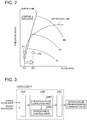
- FIG. 2 is a compressor map showing the operation characteristics of a compressor.
- x-axis is the flow rate and y-axis is the pressure ratio of the pressure at the inlet to that at the outlet of the compressor 10.
- the reference signs N1, N2, N3 in the drawing each represent the rotation speed of the compressor.
- the operating point P1 may shift to the left side of the surge line to enter the surge region.
- the operating point (operation line) of the compressor 10 entering the surge region represents occurrence of surging in the compressor 10.
- the bypass valve 16 is controlled to have a large valve-opening degree, to increase the flow rate of the compressed intake air guided to flow to the exhaust channel 6 from the intake channel 4.
- the turbine output increases and the operation flow rate of the compressor 10 increases (Q1 to Q2), and thereby the operation point P2 shifts out of the surge region.
- surging is prevented.
- FIG. 3 is a block diagram for describing the function of a turbo ECU.
- the turbo ECU 24 is a control unit independent from an engine electronic control unit (ECU) 22 for controlling the operation state of the engine body 2, and includes a control part 24B and a signal input part 24A separate and independent from the engine ECU 22.
- the turbo ECU 24 and the engine ECU 22 are configured as a microcomputer including a central processing unit (CPU), a random access memory (RAM), a read only memory (ROM), and an I/O interface.
- the turbo ECU 24 includes the signal input part 24A, the turbo control part 24B, and a signal output part 24C.
- signals related to an intake flow rate measured by the airflow meter 31 and a boost pressure measured by the pressure sensor 33 are inputted.
- the turbo control part 24B includes an operation-point computing part 24B1 and a bypass-valve control part 24B2.
- the operation-point computing part 24B1 computes the operation point of the compressor 10 from the compressor map illustrated in FIG. 2 , from the intake flow rate and the boost pressure inputted into the signal input part 24A.
- the bypass-valve control part 24B2 generates a bypass-valve opening degree command value such that increases the valve opening degree of the bypass valve 16, when the operation point computed by the operation-point computing part 24B1 is in the vicinity of the surge region.
- the signal related to the generated bypass-valve opening degree command value is outputted to the bypass valve 16 from the signal output part 24C, and thereby the valve opening degree of the bypass valve 16 is controlled.
- the control logic and hardware configuration of the engine ECU 22 have become increasingly complicated.
- the bypass-valve control part 24B2 for controlling the valve opening degree of the bypass valve 16 is mounted to the engine ECU 22, the control logic and hardware configuration of the engine ECU 22 would become even more complicated.
- communication delay of the engine ECU may be a problem.
- the turbo ECU 24 itself computes the operation point of the compressor 10 and controls the valve opening degree of the bypass valve 16 on the basis of the computed operation point, it is possible to control the bypass valve 16 quickly while avoiding an influence of communication delay as compared to a case where the engine ECU 22 controls the valve opening degree of the bypass valve 16.
- the heating unit 18 is to heat the compressed intake air flowing through the bypass channel 14.
- a heater may be provided, for instance, to be used as a heat source, or exhaust gas discharged from the engine body 2 may be used as a heat source as in the embodiments described below.
- the intake bypass device 20 includes the heating unit 18 for heating the compressed intake air flowing through the bypass channel 14, and is configured so that the compressed intake air having been heated is guided to flow to the upstream side of the turbine 8.
- the heating unit 18 for heating the compressed intake air flowing through the bypass channel 14, and is configured so that the compressed intake air having been heated is guided to flow to the upstream side of the turbine 8.
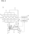
- FIG. 4 is an overall configuration diagram of an engine system including an intake bypass device according to the second embodiment of the present invention.
- the engine system 1a of the present embodiment basically has a similar configuration to that of the engine system 1 of the above described embodiment, except for the above described heating unit 18.
- the same components are associated with the same reference numerals and not described in detail.
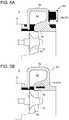
- FIG. 5 is a schematic cross-sectional view illustrating an example of a heating unit of the second embodiment.
- the heating unit 18 of the embodiment illustrated in FIGs. 5A and 5B is constituted by a turbine housing 8A of the turbine 8 forming at least a part of an inner wall surface of the bypass channel 14, at least in a partial section of the bypass channel 14.
- a part of an outer wall surface of a scroll portion 8a forming a scroll channel 8d forms a part of the inner wall surface of the bypass channel 14.
- the part of the outer wall surface of the scroll portion 8a indicated by the reference numeral 14a in the drawing corresponds to the heating unit 18 of the present embodiment.
- a through hole formed inside a shroud portion 8e of the turbine housing 8A constitutes the bypass channel 14, and an inner section of the shroud portion 8e of the turbine housing 8A forms the inner wall surface of the bypass channel 14.
- the entire inner wall surface indicated by the reference numeral 14a in the drawing corresponds to the heating unit 18 of the present embodiment.
- the reference numeral 8b indicates a hub
- 8c indicates an impeller
- 9 indicates a bearing housing.
- FIG. 6 is a schematic cross-sectional view illustrating another example of a heating unit of the second embodiment.
- a part of the turbine housing 8A has a dual structure including an inner housing 8A1 formed of sheet metal forming the scroll channel 8d and an outer housing 8A2 formed of sheet metal covering the inner housing 8A1.
- the space defined by the inner housing 8A1 and the outer housing 8A2 forms a partial section of the above described bypass channel 14.
- an outer wall surface of the inner housing 8A1 forms a part of the inner wall surface of the bypass channel 14, and the outer wall surface (indicated by the reference numeral 14a in the drawing) of the inner housing 8A1 corresponds to the heating unit 18 of the present embodiment.
- the space defined by the inner housing 8A1 and the outer housing 8A2 constitutes a partial section of the above described bypass channel, and the compressed intake air flows through this space, which makes it possible to heat the compressed intake air and cool the turbine housing 8A efficiently.
- FIG. 7 is an overall configuration diagram of an engine system including an intake bypass device according to the third embodiment of the present invention.
- the engine system 1b of the present embodiment further includes an exhaust-gas purification device 26 for purifying exhaust gas discharged from the engine body 2.
- the exhaust-gas purification device 26 is disposed on the downstream side of the turbine 8 in the exhaust channel 6.
- the above described heating unit 18 is disposed on the downstream side of the exhaust-gas purification device 26.
- the engine system 1b of the present embodiment has a similar configuration to that of the above described embodiment, and thus the same components are associated with the same reference numerals and not described in detail.
- FIG. 8 is a schematic cross-sectional view illustrating an example of a heating unit of the third embodiment.
- the heating unit 18 of the embodiment illustrated in FIG. 8 is constituted by a part of an outer surface of an exhaust duct 6a of the exhaust channel 6 at the downstream side of the exhaust-gas purification device 26 forming at least a part of the inner wall surface of the bypass channel 14, in a partial section of the bypass channel 14.
- the part of the outer surface of the exhaust duct 6a indicated by the reference numeral 14a in the drawing corresponds to the heating unit 18 of the present embodiment.
- FIG. 9 is a schematic cross-sectional view illustrating another example of a heating unit of the third embodiment.
- the exhaust channel 6 at the downstream side of the exhaust-gas purification device 26 has a dual structure including an inner exhaust duct 6b through which the exhaust gas flows and an outer exhaust duct 6c covering the inner exhaust duct.
- the space defined by the inner exhaust duct 6b and the outer exhaust duct 6c forms a partial section of the above described bypass channel 14.
- an outer surface of the inner exhaust duct 6b forms a part of the inner wall surface of the bypass channel 14, and the outer surface (indicated by the reference numeral 14a in the drawing) of the inner exhaust duct 6b corresponds to the heating unit 18 of the present embodiment.
- the space defined by the inner exhaust duct 6b and the outer exhaust duct 6c constitutes a partial section of the above described bypass channel, and the compressed intake air flows through this space, which makes it possible to heat the compressed intake air efficiently.
- FIG. 10 is an overall configuration diagram of an engine system including an intake bypass device according to the fourth embodiment of the present invention.
- the engine system 1c of the present embodiment basically has a similar configuration to that of the engine system 1 of the above described embodiment, except for the above described heating unit 18.
- the same components are associated with the same reference numerals and not described in detail.
- FIG. 11 is a schematic cross-sectional view illustrating an example of a heating unit of the fourth embodiment.
- the heating unit 18 of the embodiment illustrated in FIG. 11 is constituted by a part of an outer wall surface of an exhaust manifold 7 forming a part of the inner wall surface of the bypass channel 14, in a partial section of the bypass channel 14.
- the part of the outer surface of the exhaust manifold 7 indicated by the reference numeral 14a in the drawing corresponds to the heating unit 18 of the present embodiment.
- FIG. 12 is a schematic cross-sectional view illustrating another example of a heating unit of the fourth embodiment.
- the exhaust manifold 7 has a dual structure including an inner exhaust manifold 7a through which the exhaust gas flows and an outer exhaust manifold 7b covering the inner exhaust manifold 7a.
- the space defined by the inner exhaust manifold 7a and the outer exhaust manifold 7b forms a partial section of the above described bypass channel 14.
- an outer surface of the inner exhaust manifold 7a forms a part of the inner wall surface of the bypass channel 14, and the outer surface (indicated by the reference numeral 14a in the drawing) of the inner exhaust manifold 7a corresponds to the heating unit 18 of the present embodiment.
- the space defined by the inner exhaust manifold 7a and the outer exhaust manifold 7b constitutes a partial section of the above described bypass channel 14, and the compressed intake air flows through this space, which makes it possible to heat the compressed intake air and cool the exhaust manifold 7 efficiently.
- At least one embodiment of the present invention can be suitably used in an engine including a turbocharger for not only automobiles but also for ships and other industrial usages.
Landscapes
- Engineering & Computer Science (AREA)
- Chemical & Material Sciences (AREA)
- Mechanical Engineering (AREA)
- General Engineering & Computer Science (AREA)
- Combustion & Propulsion (AREA)
- Chemical Kinetics & Catalysis (AREA)
- Health & Medical Sciences (AREA)
- Toxicology (AREA)
- Sustainable Development (AREA)
- Life Sciences & Earth Sciences (AREA)
- Physics & Mathematics (AREA)
- Fluid Mechanics (AREA)
- General Chemical & Material Sciences (AREA)
- Computer Hardware Design (AREA)
- Microelectronics & Electronic Packaging (AREA)
- Supercharger (AREA)
Abstract
Description
- The present disclosure relates to an engine system including an intake bypass device for guiding a part of compressed intake air compressed by a compressor to an upstream side of a turbine bypassing an engine body.
- As a technique to improve an output of an engine, a method (supercharging) of compressing intake air with a turbocharger and supplying an engine with the compressed intake air is known, and widely used in engines for automobiles and the like. Especially in recent years, supercharging is applied to a wide operation range of from a low-output range to a high-output range, in view of the regulations on exhaust gas and fuel consumption rate that have become increasingly stricter.
- On the other hand, in a turbocharger, surging may occur transitionally depending on the operation state of the turbocharger. Occurrence of surging in a turbocharger may lead to breakage of various devices such as an impeller, and thus needs to be prevented as much as possible. In view of this, a technique to widen the operation range of a compressor while avoiding occurrence of surging has been required.
- A known technique to widen the operation range of a compressor while avoiding occurrence of surging is an intake bypass device which guides a part of compressed intake air compressed by a compressor to flow to an upstream side of a turbine bypassing an engine body, as disclosed in
Patent Document 1, for instance. - The intake bypass device of
Patent Document 1 includes a bypass channel connecting a downstream side of the compressor in an intake channel and an upstream side of the turbine in an exhaust channel, and a flow-rate adjustment valve disposed in the bypass channel. The flow-rate adjustment valve is controlled so that the valve opening degree increases when the operation point of the compressor enters the vicinity of a surge region. When the valve opening degree of the flow-rate adjustment valve increases, the flow rate of the compressed intake air guided to flow to the upstream side of the turbine via the bypass channel increases. As a result, the turbine output increases and the operation flow rate of the compressor increases, which makes it possible to prevent surging. - Patent Document 1:
JP2000-64844A - However, in the intake bypass device disclosed in the above described
Patent Document 1, compressed intake air having a relatively low temperature merges with exhaust gas having a high temperature discharged from the engine, and the turbine is driven by the exhaust gas having incorporated the compressed intake air. Thus, the energy of exhaust gas that drives the turbine may decrease, and the output of the turbine may be insufficient. - At least one embodiment of the present invention was made in view of the above conventional problem, and an object of the at least one embodiment is to provide an engine system including an intake bypass device whereby it is possible to widen an operation range of a compressor without causing an output of a turbine to become insufficient.
- An engine system according to at least one embodiment of the present invention comprises: an engine body; an intake channel for supplying intake air to the engine body; an exhaust channel through which exhaust gas discharged from the engine body flows; a turbocharger including a turbine disposed in the exhaust channel and driven by energy of the exhaust gas discharged from the engine body, and a compressor disposed in the intake channel and driven coaxially with the turbine; and an intake bypass device for guiding a part of compressed intake air compressed by the compressor to flow to an upstream side of the turbine bypassing the engine body. The intake bypass device includes a bypass channel connecting a downstream side of the compressor in the intake channel and an upstream side of the turbine in the exhaust channel, a bypass valve disposed in the bypass channel and configured to control a flow of the compressed intake air in the bypass channel, and a heating unit for heating the compressed intake air flowing through the bypass channel.
- In the engine system including the above intake bypass device, the intake bypass device includes the heating unit for heating the compressed intake air flowing through the bypass channel, and is configured so that the compressed intake air having been heated is guided to flow to the upstream side of the turbine. Thus, it is possible to prevent a decrease in the energy of the exhaust gas for driving the turbine and to prevent shortage of the output of the turbine.
- In some embodiments, the heating unit is configured to utilize the exhaust gas discharged from the engine body as a heat source for heating the compressed intake air flowing through the bypass channel.
- According to the above embodiment, it is possible to heat the compressed intake air flowing through the bypass channel by effectively utilizing the thermal energy of the exhaust gas discharged from the engine body without providing an additional heat source such as a heater separately.
- In some embodiments, the heating unit comprises a turbine housing of the turbine forming at least a part of an inner wall surface of the bypass channel, in a partial section of the bypass channel.
- According to the above embodiment, it is possible to heat the compressed intake air flowing through the bypass channel using the thermal energy of the exhaust gas flowing through the turbine housing. In addition, since it is possible to cool the turbine housing with the compressed intake air flowing through the bypass channel, it is no longer necessary to use an expensive heat-resistant material for the turbine housing, which makes it possible to reduce the cost.
- In the above embodiment, at least a part of the turbine housing has a dual structure including an inner housing formed of sheet metal and an outer housing formed of sheet metal covering the inner housing. Further, the space defined by the inner housing and the outer housing forms a partial section of the bypass channel in the above embodiment.
- According to the above embodiment, the space defined by the inner housing and the outer housing constitutes a partial section of the bypass channel in the above embodiment, and the compressed intake air flows through this space, which makes it possible to heat the compressed intake air and cool the turbine housing efficiently.
- In some embodiments, the engine system further comprises an exhaust-gas purification device for purifying the exhaust gas discharged from the engine body. The exhaust-gas purification device is disposed on a downstream side of the turbine in the exhaust channel. The heating unit comprises the exhaust channel on a downstream side of the exhaust-gas purification device forming at least a part of an inner wall surface of the bypass channel, in a partial section of the bypass channel.
- According to the above embodiment, it is possible to heat the compressed intake air flowing through the bypass channel using the thermal energy of the exhaust gas flowing through the exhaust channel. In addition, since the remaining thermal energy of the exhaust gas after having driven the turbine and passed through the exhaust-gas purification device to heat a medium is recovered, it is possible to heat the compressed intake air without affecting the output of the turbine or the purification performance of the exhaust-gas purification device.
- In the above embodiments, at least a part of the exhaust channel on the downstream side of the exhaust-gas purification device has a dual structure including an inner exhaust duct through which the exhaust gas flows and an outer exhaust duct covering the inner exhaust duct. Further, a space defined by the inner exhaust duct and the outer exhaust duct forms a partial section of the bypass channel.
- According to the above embodiment, the space defined by the inner exhaust duct and the outer exhaust duct constitutes a partial section of the bypass channel in the above embodiment, and the compressed intake air flows through this space, which makes it possible to heat the compressed intake air efficiently.
- In some embodiments, the heating unit comprises an exhaust manifold connecting the engine body and the exhaust channel forming at least a part of an inner wall surface of the bypass channel, in a partial section of the bypass channel.
- According to the above embodiment, it is possible to heat the compressed intake air flowing through the bypass channel using the thermal energy of the exhaust gas flowing through the exhaust manifold. In addition, since the heat is exchanged with the high-temperature exhaust gas flowing through the exhaust manifold, it is no longer necessary to use an expensive thermal-resistant material for the exhaust manifold and the exhaust channel or the like disposed on the downstream side of the exhaust manifold, which makes it possible to reduce the cost.
- In the above embodiments, at least a part of the exhaust manifold has a dual structure including an inner exhaust manifold through which the exhaust gas flows and an outer exhaust manifold covering the inner exhaust manifold. Further, a space defined by the inner exhaust manifold and the outer exhaust manifold forms a partial section of the bypass channel.
- According to the above embodiment, the space defined by the inner exhaust manifold and the outer exhaust manifold constitutes a partial section of the bypass channel in the above embodiment, and the compressed intake air flows through this space, which makes it possible to heat the compressed intake air and cool the exhaust manifold efficiently.
- In some embodiments, the intake bypass device includes a turbo control unit including a control part and a signal input part separate and independent from an engine control unit for controlling an operation state of the engine body, and the turbo control unit includes a bypass-valve control part for controlling a valve opening degree of the bypass valve.
- In accordance with the improvement of the engines in recent years, the control logic and hardware configuration of an engine controller is becoming increasingly complicated. Thus, if the bypass-valve control part for controlling the valve opening degree of the bypass valve is mounted to the engine controller, the control logic and hardware configuration of the engine would become even more complicated. Further, if a quickly-changing transitional phenomenon like surging is to be controlled by an engine controller having a control logic and hardware configuration which are complicated, communication delay of the engine controller may be a problem.
- Thus, as in the present embodiment, it is possible to prevent the engine control unit from becoming complicated by mounting the bypass-valve control part to the turbo control unit configured separately from the engine control unit.
- In the above embodiment, the turbo control unit includes a turbo signal input part into which a sensor signal related to an operation state of the engine such as a boost pressure, an intake flow rate, an engine rotation speed, and a turbo rotation speed is inputted, and a turbo control part including an operation-point computing part and the bypass-valve control part, the operation-point computing part being configured to compute an operation point of the compressor on the basis of the sensor signal inputted into the turbo signal input part. Further, the bypass-valve control part is configured to control the valve opening degree of the bypass valve to increase when the operation point computed by the operation-point computing part is in the vicinity of a surge region.
- According to the above embodiment, since the turbo control unit itself computes the operation point of the compressor and controls the valve opening degree of the bypass valve on the basis of the computed operation point, it is possible to control the bypass valve quickly while avoiding an influence of communication delay as compared to a case where the engine control unit controls the valve opening degree of the bypass valve.
- In the above embodiment, the sensor signal comprises a sensor signal related to a boost pressure of the compressed intake air compressed by the compressor and to an intake flow rate of the intake air flowing through the compressor.
- According to the above embodiment, it is possible to compute the operation point of the compressor from the boost pressure and the intake flow rate accurately.
- According to at least one embodiment of the present invention, it is possible to provide a DPF regeneration control device whereby it is possible to prevent clogging of a DOC more efficiently than the conventional technique, and to recover the DOC securely from the clogging even if the DOC is actually clogged.
-
-
FIG. 1 is an overall configuration diagram of an engine system including an intake bypass device according to the first embodiment of the present invention. -
FIG. 2 is a compressor map showing the operation characteristics of a compressor. -
FIG. 3 is a block diagram for describing the function of a turbo ECU. -
FIG. 4 is an overall configuration diagram of an engine system including an intake bypass device according to the second embodiment of the present invention. -
FIG. 5 is a schematic cross-sectional view illustrating an example of a heating unit of the second embodiment. -
FIG. 6 is a schematic cross-sectional view illustrating another example of a heating unit of the second embodiment. -
FIG. 7 is an overall configuration diagram of an engine system including an intake bypass device according to the third embodiment of the present invention. -
FIG. 8 is a schematic cross-sectional view illustrating an example of a heating unit of the third embodiment. -
FIG. 9 is a schematic cross-sectional view illustrating another example of a heating unit of the third embodiment. -
FIG. 10 is an overall configuration diagram of an engine system including an intake bypass device according to the fourth embodiment of the present invention. -
FIG. 11 is a schematic cross-sectional view illustrating an example of a heating unit of the fourth embodiment. -
FIG. 12 is a schematic cross-sectional view illustrating another example of a heating unit of the fourth embodiment. - Embodiments of the present invention will now be described in more detail with reference to the accompanying drawings.
- However, the scope of the present invention is not limited to the following embodiments. It is intended that dimensions, materials, shapes, relative positions and the like of components described in the embodiments shall be interpreted as illustrative only and not limitative of the scope of the present invention.
-
FIG. 1 is an overall configuration diagram of an engine system including an intake bypass device according to the first embodiment of the present invention. - As illustrated in
FIG. 1 , theengine system 1 of the present embodiment at least includes anengine body 2, anintake channel 4 for supplying intake air tocylinders 2a of theengine body 2, anexhaust channel 6 for carrying exhaust gas discharged from thecylinders 2a of theengine body 2, aturbocharger 12 for compressing intake air to be supplied to theengine body 2, and anintake bypass device 20 for guiding a part of the compressed intake air compressed by theturbocharger 12 to theexhaust channel 6 bypassing theengine body 2. - The
engine body 2 includes a plurality ofcylinders 2a. Theengine body 2 and theintake channel 4 are connected to each other via anintake manifold 5, and theintake manifold 5 distributes the intake air flowing through theintake channel 4 to each of the plurality ofcylinders 2a. Further, theengine body 2 and theexhaust channel 6 are connected to each other via anexhaust manifold 7, and theexhaust manifold 7 collects the exhaust air discharged from the plurality ofcylinders 2a into theexhaust channel 6. - The
turbocharger 12 includes aturbine 8 disposed in theexhaust channel 6, and acompressor 10 disposed in theintake channel 4 and coupled to theturbine 8 via a rotor to be driven coaxially with theturbine 8. Theturbine 8 is driven by exhaust energy of the exhaust gas discharged from theengine body 2, and thereby thecompressor 10 is coaxially driven, so as to compress the intake air flowing through theintake channel 4. - Further, on the upstream side of the
compressor 10 of theintake channel 4, anairflow meter 31 for measuring an intake flow rate is disposed. Further, on the downstream side of thecompressor 10 of theintake channel 4, apressure sensor 33 for measuring a boost pressure of the compressed intake air is disposed. - The
intake bypass device 20 includes abypass channel 14 connecting the downstream side of thecompressor 10 in theintake channel 4 and the upstream side of theturbine 8 in theexhaust channel 6, abypass valve 16 disposed in thebypass channel 14, and aheating unit 18 for heating the compressed intake air flowing through thebypass channel 14. - The
bypass valve 16 of the present embodiment is configured as a flow-rate control valve for controlling the flow rate of the compressed intake air guided to flow to theexhaust channel 6 from theintake channel 4. The valve opening degree of thebypass valve 16 is controlled by a turbo ECU (turbo control unit) 24 described below, so that surging does not occur in thecompressor 10. In the present invention, the type of thebypass valve 16 is not limited to a flow-rate control valve. It is sufficient if thebypass valve 16 can at least prevent a backward flow of the exhaust gas from theexhaust channel 6 to theintake channel 4, and thebypass valve 16 may be a check valve or the like. -
FIG. 2 is a compressor map showing the operation characteristics of a compressor. In the drawing, x-axis is the flow rate and y-axis is the pressure ratio of the pressure at the inlet to that at the outlet of thecompressor 10. The reference signs N1, N2, N3 in the drawing each represent the rotation speed of the compressor. - As illustrated in
FIG. 2 , when thecompressor 10 is operating at a small flow rate and at a high pressure ratio, the operating point P1 may shift to the left side of the surge line to enter the surge region. The operating point (operation line) of thecompressor 10 entering the surge region represents occurrence of surging in thecompressor 10. Thus, when the operation point (operation line) of thecompressor 10 is in the vicinity of the surge region, thebypass valve 16 is controlled to have a large valve-opening degree, to increase the flow rate of the compressed intake air guided to flow to theexhaust channel 6 from theintake channel 4. In this way, the turbine output increases and the operation flow rate of thecompressor 10 increases (Q1 to Q2), and thereby the operation point P2 shifts out of the surge region. As a result, surging is prevented. -
FIG. 3 is a block diagram for describing the function of a turbo ECU. - The
turbo ECU 24 is a control unit independent from an engine electronic control unit (ECU) 22 for controlling the operation state of theengine body 2, and includes acontrol part 24B and asignal input part 24A separate and independent from theengine ECU 22. Theturbo ECU 24 and theengine ECU 22 are configured as a microcomputer including a central processing unit (CPU), a random access memory (RAM), a read only memory (ROM), and an I/O interface. - As illustrated in
FIG. 3 , theturbo ECU 24 includes thesignal input part 24A, theturbo control part 24B, and asignal output part 24C. To thesignal input part 24A, signals related to an intake flow rate measured by theairflow meter 31 and a boost pressure measured by thepressure sensor 33 are inputted. Theturbo control part 24B includes an operation-point computing part 24B1 and a bypass-valve control part 24B2. The operation-point computing part 24B1 computes the operation point of thecompressor 10 from the compressor map illustrated inFIG. 2 , from the intake flow rate and the boost pressure inputted into thesignal input part 24A. The bypass-valve control part 24B2 generates a bypass-valve opening degree command value such that increases the valve opening degree of thebypass valve 16, when the operation point computed by the operation-point computing part 24B1 is in the vicinity of the surge region. The signal related to the generated bypass-valve opening degree command value is outputted to thebypass valve 16 from thesignal output part 24C, and thereby the valve opening degree of thebypass valve 16 is controlled. - In accordance with the improvement of the engines in recent years, the control logic and hardware configuration of the
engine ECU 22 have become increasingly complicated. Thus, if the bypass-valve control part 24B2 for controlling the valve opening degree of thebypass valve 16 is mounted to theengine ECU 22, the control logic and hardware configuration of theengine ECU 22 would become even more complicated. Further, if a quickly-changing transitional phenomenon like surging is to be controlled by an engine ECU having a control logic and hardware configuration which are complicated, communication delay of the engine ECU may be a problem. - Thus, as in the present embodiment, it is possible to prevent the
engine ECU 22 from becoming complicated by mounting the bypass-valve control part 24B2 to theturbo ECU 24 configured separately from theengine ECU 22. Further, since theturbo ECU 24 itself computes the operation point of thecompressor 10 and controls the valve opening degree of thebypass valve 16 on the basis of the computed operation point, it is possible to control thebypass valve 16 quickly while avoiding an influence of communication delay as compared to a case where theengine ECU 22 controls the valve opening degree of thebypass valve 16. - The
heating unit 18 is to heat the compressed intake air flowing through thebypass channel 14. As the heating unit 28, a heater may be provided, for instance, to be used as a heat source, or exhaust gas discharged from theengine body 2 may be used as a heat source as in the embodiments described below. - In the
engine system 1 including the aboveintake bypass device 20, theintake bypass device 20 includes theheating unit 18 for heating the compressed intake air flowing through thebypass channel 14, and is configured so that the compressed intake air having been heated is guided to flow to the upstream side of theturbine 8. Thus, it is possible to prevent a decrease in the energy of the exhaust gas for driving theturbine 8 and to prevent insufficiency of the output of theturbine 8. -
FIG. 4 is an overall configuration diagram of an engine system including an intake bypass device according to the second embodiment of the present invention. Theengine system 1a of the present embodiment basically has a similar configuration to that of theengine system 1 of the above described embodiment, except for the above describedheating unit 18. Thus, the same components are associated with the same reference numerals and not described in detail. -
FIG. 5 is a schematic cross-sectional view illustrating an example of a heating unit of the second embodiment. Theheating unit 18 of the embodiment illustrated inFIGs. 5A and 5B is constituted by aturbine housing 8A of theturbine 8 forming at least a part of an inner wall surface of thebypass channel 14, at least in a partial section of thebypass channel 14. - In the embodiment illustrated in
FIG. 5A , in theturbine housing 8A, a part of an outer wall surface of ascroll portion 8a forming ascroll channel 8d forms a part of the inner wall surface of thebypass channel 14. The part of the outer wall surface of thescroll portion 8a indicated by thereference numeral 14a in the drawing corresponds to theheating unit 18 of the present embodiment. Further, in the embodiment illustrated inFIG. 5B , a through hole formed inside ashroud portion 8e of theturbine housing 8A constitutes thebypass channel 14, and an inner section of theshroud portion 8e of theturbine housing 8A forms the inner wall surface of thebypass channel 14. The entire inner wall surface indicated by thereference numeral 14a in the drawing corresponds to theheating unit 18 of the present embodiment. In the drawing, thereference numeral 8b indicates a hub, 8c indicates an impeller, and 9 indicates a bearing housing. - According to the above embodiment, it is possible to heat the compressed intake air flowing through the
bypass channel 14 with the thermal energy of the exhaust gas flowing through theturbine housing 8A, which makes is possible to prevent a decrease in the energy of the exhaust gas for driving theturbine 8 and to prevent insufficiency of the output of theturbine 8. In addition, since it is possible to cool theturbine housing 8A with the compressed intake air flowing through thebypass channel 14, it is no longer necessary to use an expensive heat-resistant material for theturbine housing 8A, which makes it possible to reduce the cost. -
FIG. 6 is a schematic cross-sectional view illustrating another example of a heating unit of the second embodiment. In the embodiment illustrated inFIG. 6 , a part of theturbine housing 8A has a dual structure including an inner housing 8A1 formed of sheet metal forming thescroll channel 8d and an outer housing 8A2 formed of sheet metal covering the inner housing 8A1. The space defined by the inner housing 8A1 and the outer housing 8A2 forms a partial section of the above describedbypass channel 14. Specifically, an outer wall surface of the inner housing 8A1 forms a part of the inner wall surface of thebypass channel 14, and the outer wall surface (indicated by thereference numeral 14a in the drawing) of the inner housing 8A1 corresponds to theheating unit 18 of the present embodiment. - According to the above embodiment, the space defined by the inner housing 8A1 and the outer housing 8A2 constitutes a partial section of the above described bypass channel, and the compressed intake air flows through this space, which makes it possible to heat the compressed intake air and cool the
turbine housing 8A efficiently. -
FIG. 7 is an overall configuration diagram of an engine system including an intake bypass device according to the third embodiment of the present invention. Theengine system 1b of the present embodiment further includes an exhaust-gas purification device 26 for purifying exhaust gas discharged from theengine body 2. The exhaust-gas purification device 26 is disposed on the downstream side of theturbine 8 in theexhaust channel 6. The above describedheating unit 18 is disposed on the downstream side of the exhaust-gas purification device 26. For the rest, theengine system 1b of the present embodiment has a similar configuration to that of the above described embodiment, and thus the same components are associated with the same reference numerals and not described in detail. -
FIG. 8 is a schematic cross-sectional view illustrating an example of a heating unit of the third embodiment. Theheating unit 18 of the embodiment illustrated inFIG. 8 is constituted by a part of an outer surface of anexhaust duct 6a of theexhaust channel 6 at the downstream side of the exhaust-gas purification device 26 forming at least a part of the inner wall surface of thebypass channel 14, in a partial section of thebypass channel 14. The part of the outer surface of theexhaust duct 6a indicated by thereference numeral 14a in the drawing corresponds to theheating unit 18 of the present embodiment. - According to the above embodiment, it is possible to heat the compressed intake air flowing through the
bypass channel 14 with the thermal energy of the exhaust gas flowing through theexhaust channel 6, which makes is possible to prevent a decrease in the energy of the exhaust gas for driving theturbine 8 and to prevent shortage of the output of theturbine 8. In addition, since the remaining thermal energy of the exhaust gas after having driven theturbine 8 and passed through the exhaust-gas purification device 26 to heat a medium is recovered, it is possible to heat the compressed intake air without affecting the output of theturbine 8 or the purification performance of the exhaust-gas purification device 26. -
FIG. 9 is a schematic cross-sectional view illustrating another example of a heating unit of the third embodiment. In the embodiment illustrated inFIG. 9 , at least a part of theexhaust channel 6 at the downstream side of the exhaust-gas purification device 26 has a dual structure including aninner exhaust duct 6b through which the exhaust gas flows and anouter exhaust duct 6c covering the inner exhaust duct. The space defined by theinner exhaust duct 6b and theouter exhaust duct 6c forms a partial section of the above describedbypass channel 14. Specifically, an outer surface of theinner exhaust duct 6b forms a part of the inner wall surface of thebypass channel 14, and the outer surface (indicated by thereference numeral 14a in the drawing) of theinner exhaust duct 6b corresponds to theheating unit 18 of the present embodiment. - According to the above embodiment, the space defined by the
inner exhaust duct 6b and theouter exhaust duct 6c constitutes a partial section of the above described bypass channel, and the compressed intake air flows through this space, which makes it possible to heat the compressed intake air efficiently. -
FIG. 10 is an overall configuration diagram of an engine system including an intake bypass device according to the fourth embodiment of the present invention. Theengine system 1c of the present embodiment basically has a similar configuration to that of theengine system 1 of the above described embodiment, except for the above describedheating unit 18. Thus, the same components are associated with the same reference numerals and not described in detail. -
FIG. 11 is a schematic cross-sectional view illustrating an example of a heating unit of the fourth embodiment. Theheating unit 18 of the embodiment illustrated inFIG. 11 is constituted by a part of an outer wall surface of anexhaust manifold 7 forming a part of the inner wall surface of thebypass channel 14, in a partial section of thebypass channel 14. The part of the outer surface of theexhaust manifold 7 indicated by thereference numeral 14a in the drawing corresponds to theheating unit 18 of the present embodiment. - According to the above embodiment, it is possible to heat the compressed intake air flowing through the
bypass channel 14 with the thermal energy of the exhaust gas flowing through theexhaust manifold 7, which makes is possible to prevent a decrease in the energy of the exhaust gas for driving theturbine 8 and to prevent shortage of the output of theturbine 8. In addition, since the heat is exchanged with the high-temperature exhaust gas flowing through theexhaust manifold 7, it is no longer necessary to use an expensive thermal-resistant material for theexhaust manifold 7 and theexhaust channel 6 or the like disposed on the downstream side of theexhaust manifold 7, which makes it possible to reduce the cost. -
FIG. 12 is a schematic cross-sectional view illustrating another example of a heating unit of the fourth embodiment. In the embodiment illustrated inFIG. 12 , at least a part of theexhaust manifold 7 has a dual structure including aninner exhaust manifold 7a through which the exhaust gas flows and anouter exhaust manifold 7b covering theinner exhaust manifold 7a. The space defined by theinner exhaust manifold 7a and theouter exhaust manifold 7b forms a partial section of the above describedbypass channel 14. Specifically, an outer surface of theinner exhaust manifold 7a forms a part of the inner wall surface of thebypass channel 14, and the outer surface (indicated by thereference numeral 14a in the drawing) of theinner exhaust manifold 7a corresponds to theheating unit 18 of the present embodiment. - According to the above embodiment, the space defined by the
inner exhaust manifold 7a and theouter exhaust manifold 7b constitutes a partial section of the above describedbypass channel 14, and the compressed intake air flows through this space, which makes it possible to heat the compressed intake air and cool theexhaust manifold 7 efficiently. - The embodiments of the present invention have been described above. However, the present invention is not limited thereto. For instance, various modifications may be applied as long as they do not depart from the object of the present invention.
- At least one embodiment of the present invention can be suitably used in an engine including a turbocharger for not only automobiles but also for ships and other industrial usages.
-
- 1, 1a to 1c
- Engine system
- 2
- Engine body
- 2a
- Cylinder
- 4
- Intake channel
- 5
- Intake manifold
- 6
- Exhaust channel
- 6a
- Exhaust duct
- 6b
- Inner exhaust duct
- 6c
- Outer exhaust duct
- 7
- Exhaust manifold
- 7a
- Inner exhaust manifold
- 7b
- Outer exhaust manifold
- 8
- Turbine
- 8A
- Turbine housing
- 8A1
- Inner housing
- 8A2
- Outer housing
- 8a
- Scroll portion
- 8b
- Hub
- 8c
- Impeller
- 8d
- Scroll channel
- 8e
- Shroud portion
- 10
- Compressor
- 12
- Turbocharger
- 14
- Bypass channel
- 16
- Bypass valve
- 18
- Heating unit
- 20
- Intake bypass device
- 22
- Engine ECU
- 24
- Turbo ECU
- 26
- Exhaust-gas purification device
- 31
- Airflow meter
- 33
- Pressure sensor
Claims (11)
- An engine system comprising:an engine body;an intake channel for supplying intake air to the engine body;an exhaust channel through which exhaust gas discharged from the engine body flows;a turbocharger including a turbine disposed in the exhaust channel and driven by energy of the exhaust gas discharged from the engine body, and a compressor disposed in the intake channel and driven coaxially with the turbine; andan intake bypass device for guiding a part of compressed intake air compressed by the compressor to flow to an upstream side of the turbine bypassing the engine body,wherein the intake bypass device includesa bypass channel connecting a downstream side of the compressor in the intake channel and an upstream side of the turbine in the exhaust channel,a bypass valve disposed in the bypass channel and configured to control a flow of the compressed intake air in the bypass channel, anda heating unit for heating the compressed intake air flowing through the bypass channel.
- The engine system according to claim 1,
wherein the heating unit is configured to utilize the exhaust gas discharged from the engine body as a heat source for heating the compressed intake air flowing through the bypass channel. - The engine system according to claim 2,
wherein the heating unit comprises a turbine housing of the turbine forming at least a part of an inner wall surface of the bypass channel, in a partial section of the bypass channel. - The engine system according to claim 3,
wherein at least a part of the turbine housing has a dual structure including an inner housing formed of sheet metal and an outer housing formed of sheet metal and covering the inner housing, and a space defined by the inner housing and the outer housing forms a partial section of the bypass channel. - The engine system according to claim 2,
further comprising an exhaust-gas purification device for purifying the exhaust gas discharged from the engine body, the exhaust-gas purification device being disposed on a downstream side of the turbine in the exhaust channel,
wherein the heating unit comprises the exhaust channel on a downstream side of the exhaust-gas purification device forming at least a part of an inner wall surface of the bypass channel, in a partial section of the bypass channel. - The engine system according to claim 5,
wherein at least a part of the exhaust channel on the downstream side of the exhaust-gas purification device has a dual structure including an inner exhaust duct through which the exhaust gas flows and an outer exhaust duct covering the inner exhaust duct, and a space defined by the inner exhaust duct and the outer exhaust duct forms a partial section of the bypass channel. - The engine system according to claim 2,
wherein the heating unit comprises an exhaust manifold connecting the engine body and the exhaust channel forming at least a part of an inner wall surface of the bypass channel, in a partial section of the bypass channel. - The engine system according to claim 7,
wherein at least a part of the exhaust manifold has a dual structure including an inner exhaust manifold through which the exhaust gas flows and an outer exhaust manifold covering the inner exhaust manifold, and a space defined by the inner exhaust manifold and the outer exhaust manifold forms a partial section of the bypass channel. - The engine system according to claim 1,
wherein the intake bypass device includes a turbo control unit including a control part and a signal input part separate and independent from an engine control unit for controlling an operation state of the engine body, and the turbo control unit includes a bypass-valve control part for controlling a valve opening degree of the bypass valve. - The engine system according to claim 9,
wherein the turbo control unit includesa turbo signal input part into which a sensor signal related to an operation state of the engine is inputted, anda turbo control part including an operation-point computing part and the bypass-valve control part, the operation-point computing part being configured to compute an operation point of the compressor on the basis of the sensor signal inputted into the turbo signal input part,wherein the bypass-valve control part is configured to control the valve opening degree of the bypass valve to increase when the operation point computed by the operation-point computing part is in the vicinity of a surge region. - The engine system according to claim 10,
wherein the sensor signal comprises a sensor signal related to a boost pressure of the compressed intake air compressed by the compressor and to an intake flow rate of the intake air flowing through the compressor.
Applications Claiming Priority (1)
| Application Number | Priority Date | Filing Date | Title |
|---|---|---|---|
| PCT/JP2013/077786 WO2015052837A1 (en) | 2013-10-11 | 2013-10-11 | Engine system provided with intake bypass device |
Publications (3)
| Publication Number | Publication Date |
|---|---|
| EP3020939A1 true EP3020939A1 (en) | 2016-05-18 |
| EP3020939A4 EP3020939A4 (en) | 2016-10-26 |
| EP3020939B1 EP3020939B1 (en) | 2019-12-04 |
Family
ID=52812684
Family Applications (1)
| Application Number | Title | Priority Date | Filing Date |
|---|---|---|---|
| EP13895188.4A Active EP3020939B1 (en) | 2013-10-11 | 2013-10-11 | Engine system provided with intake bypass device |
Country Status (5)
| Country | Link |
|---|---|
| US (1) | US9797320B2 (en) |
| EP (1) | EP3020939B1 (en) |
| JP (1) | JP6072277B2 (en) |
| CN (1) | CN105324558B (en) |
| WO (1) | WO2015052837A1 (en) |
Cited By (4)
| Publication number | Priority date | Publication date | Assignee | Title |
|---|---|---|---|---|
| EP3121432A4 (en) * | 2014-03-20 | 2017-08-16 | Nissan Motor Co., Ltd | Control device and control method for diesel engine |
| DK201670345A1 (en) * | 2016-05-24 | 2017-12-11 | Man Diesel & Turbo Filial Af Man Diesel & Turbo Se Tyskland | Method for operating a two-stroke engine system |
| AT522942A2 (en) * | 2019-12-16 | 2021-03-15 | Avl List Gmbh | COMBUSTION ENGINE |
| WO2022028886A1 (en) * | 2020-08-05 | 2022-02-10 | Daimler Ag | Internal combustion engine for a motor vehicle, and motor vehicle |
Families Citing this family (9)
| Publication number | Priority date | Publication date | Assignee | Title |
|---|---|---|---|---|
| FR3035443B1 (en) * | 2015-04-21 | 2017-04-21 | Ifp Energies Now | IMPROVED DEVICE FOR CONTROLLING THE AIR QUANTITY INTRODUCED TO THE ADMISSION OF A SUPERIOR INTERNAL COMBUSTION ENGINE AND METHOD USING SUCH A DEVICE |
| DK178780B1 (en) * | 2015-06-19 | 2017-01-23 | Man Diesel & Turbo Filial Af Man Diesel & Turbo Se Tyskland | Large two-stroke turbocharged compression ignited internal combustion engine with an exhaust gas purification system |
| EP3176396A1 (en) * | 2015-12-04 | 2017-06-07 | Winterthur Gas & Diesel Ltd. | Combustion engine and method for optimizing exhaust gas aftertreatment |
| EP3176397A1 (en) * | 2015-12-04 | 2017-06-07 | Winterthur Gas & Diesel Ltd. | Combustion engine and method for optimizing the exhaust-gas aftertreatment of a combustion engine |
| FR3051225B1 (en) * | 2016-05-11 | 2019-09-13 | IFP Energies Nouvelles | METHOD OF CONTROLLING THE QUANTITY OF AIR INTRODUCED AT THE ADMISSION OF A SUPERIOR INTERNAL COMBUSTION ENGINE BY A SINGLE-INLET TURBOCHARGER |
| US10934979B2 (en) * | 2017-05-30 | 2021-03-02 | Ford Global Technologies, Llc | Methods and system diagnosing a variable geometry compressor for an internal combustion engine |
| CN114233473B (en) * | 2021-09-19 | 2025-04-29 | 江鹏 | Engine intake bypass device |
| CN114458440B (en) * | 2021-12-28 | 2023-04-25 | 中国北方发动机研究所(天津) | Cross afterburning exhaust gas turbocharging system |
| GB2629424A (en) * | 2023-04-28 | 2024-10-30 | Jaguar Land Rover Ltd | Turbomachine housing with heating system inlet and valve |
Family Cites Families (27)
| Publication number | Priority date | Publication date | Assignee | Title |
|---|---|---|---|---|
| JPS5225486B1 (en) * | 1970-05-02 | 1977-07-08 | ||
| US4122673A (en) * | 1973-09-28 | 1978-10-31 | J. Eberspacher | Internal combustion engine with afterburning and catalytic reaction in a supercharger turbine casing |
| FR2478736A1 (en) * | 1980-03-21 | 1981-09-25 | Semt | METHOD AND SYSTEM FOR POWER GENERATION BY SUPERIOR INTERNAL COMBUSTION ENGINE |
| JP2527559B2 (en) * | 1987-06-16 | 1996-08-28 | ヤマハ発動機株式会社 | Turbocharged engine |
| DE3818230A1 (en) * | 1988-05-28 | 1989-12-07 | Johann Wimmer | Unit for increasing the charge pressure on supercharged internal combustion engines in the partial load and lower engine speed range |
| JP2921434B2 (en) * | 1995-03-24 | 1999-07-19 | トヨタ自動車株式会社 | Cooling structure of vertical engine for vehicles |
| US6003315A (en) * | 1997-03-31 | 1999-12-21 | Caterpillar Inc. | Exhaust gas recirculation system for an internal combustion engine |
| US5987885A (en) * | 1998-01-29 | 1999-11-23 | Chrysler Corporation | Combination catalytic converter and heat exchanger that maintains a catalyst substrate within an efficient operating temperature range for emmisions reduction |
| JP2000064844A (en) * | 1998-08-12 | 2000-02-29 | Mitsubishi Heavy Ind Ltd | Supercharging device for internal combustion engine |
| US6358109B1 (en) * | 1999-12-08 | 2002-03-19 | Bombardier Motor Corporation Of America | Air cooled marine engine exhaust |
| DE10062377B4 (en) * | 2000-12-14 | 2005-10-20 | Siemens Ag | Apparatus and method for heating an exhaust catalyst for a supercharged internal combustion engine |
| JP2004346776A (en) * | 2003-05-20 | 2004-12-09 | Komatsu Ltd | Internal combustion engine with air supply bypass control device |
| US6990814B2 (en) * | 2003-12-18 | 2006-01-31 | Caterpillar Inc. | Engine turbocharger control management system |
| JP4098712B2 (en) * | 2003-12-25 | 2008-06-11 | 本田技研工業株式会社 | Exhaust manifold integrated engine cooling structure |
| DE102004009109A1 (en) * | 2004-02-25 | 2005-09-15 | Borgwarner Turbo Systems Gmbh | Method for connecting a sheet metal component such as a pipe with a cast metal component such as an opening of a housing, in particular for exhaust system |
| JP4389739B2 (en) * | 2004-09-29 | 2009-12-24 | 三菱自動車工業株式会社 | Internal combustion engine with a supercharger |
| SE0501177L (en) * | 2005-05-25 | 2007-01-25 | Gm Global Tech Operations Inc | Control unit of an internal combustion engine equipped with a supercharger system as well as a system, a vehicle and a method comprising such a control unit |
| JP2007085266A (en) * | 2005-09-22 | 2007-04-05 | Toyota Motor Corp | Exhaust heat exchanger |
| JP2007162545A (en) | 2005-12-13 | 2007-06-28 | Isuzu Motors Ltd | Engine supercharger system |
| JP4940927B2 (en) | 2006-12-15 | 2012-05-30 | トヨタ自動車株式会社 | Turbocharger control device |
| JP4803059B2 (en) * | 2007-02-07 | 2011-10-26 | トヨタ自動車株式会社 | Cylinder head of internal combustion engine |
| JP2010038201A (en) * | 2008-08-01 | 2010-02-18 | Aisan Ind Co Ltd | Hollow fluid passage component and manufacturing method therefor |
| US8677751B2 (en) * | 2009-07-24 | 2014-03-25 | Vandyne Superturbo, Inc. | Rich fuel mixture super-turbocharged engine system |
| US8042335B2 (en) * | 2010-06-03 | 2011-10-25 | Ford Global Technologies, Llc | Intake air heating and exhaust cooling |
| DK177388B1 (en) | 2011-01-31 | 2013-03-04 | Man Diesel & Turbo Deutschland | Large turbocharged two-stroke diesel engine with exhaust gas recirculation |
| US8627662B2 (en) * | 2011-10-19 | 2014-01-14 | General Electric Company | Exhaust gas recirculation heat recovery system and method |
| JP5903917B2 (en) * | 2012-02-08 | 2016-04-13 | トヨタ自動車株式会社 | Cooling device for internal combustion engine |
-
2013
- 2013-10-11 US US14/911,591 patent/US9797320B2/en not_active Expired - Fee Related
- 2013-10-11 JP JP2015541405A patent/JP6072277B2/en not_active Expired - Fee Related
- 2013-10-11 EP EP13895188.4A patent/EP3020939B1/en active Active
- 2013-10-11 CN CN201380077737.7A patent/CN105324558B/en not_active Expired - Fee Related
- 2013-10-11 WO PCT/JP2013/077786 patent/WO2015052837A1/en not_active Ceased
Cited By (6)
| Publication number | Priority date | Publication date | Assignee | Title |
|---|---|---|---|---|
| EP3121432A4 (en) * | 2014-03-20 | 2017-08-16 | Nissan Motor Co., Ltd | Control device and control method for diesel engine |
| US10072590B2 (en) | 2014-03-20 | 2018-09-11 | Nissan Motor Co., Ltd. | Control device and control method for diesel engine |
| DK201670345A1 (en) * | 2016-05-24 | 2017-12-11 | Man Diesel & Turbo Filial Af Man Diesel & Turbo Se Tyskland | Method for operating a two-stroke engine system |
| AT522942A2 (en) * | 2019-12-16 | 2021-03-15 | Avl List Gmbh | COMBUSTION ENGINE |
| WO2022028886A1 (en) * | 2020-08-05 | 2022-02-10 | Daimler Ag | Internal combustion engine for a motor vehicle, and motor vehicle |
| US12025042B2 (en) | 2020-08-05 | 2024-07-02 | Mercedes-Benz Group AG | Internal combustion engine for a motor vehicle, and motor vehicle |
Also Published As
| Publication number | Publication date |
|---|---|
| JP6072277B2 (en) | 2017-02-01 |
| CN105324558A (en) | 2016-02-10 |
| CN105324558B (en) | 2018-10-09 |
| EP3020939B1 (en) | 2019-12-04 |
| WO2015052837A1 (en) | 2015-04-16 |
| US9797320B2 (en) | 2017-10-24 |
| EP3020939A4 (en) | 2016-10-26 |
| US20160215712A1 (en) | 2016-07-28 |
| JPWO2015052837A1 (en) | 2017-03-09 |
Similar Documents
| Publication | Publication Date | Title |
|---|---|---|
| EP3020939B1 (en) | Engine system provided with intake bypass device | |
| CN105822379B (en) | Engine braking device and method for operating an engine braking device | |
| JP5853403B2 (en) | Control device for internal combustion engine | |
| US20070095063A1 (en) | Apparatus and method for avoidance of turbocharger surge on locomotive diesel engines | |
| CN103930656A (en) | Blow-by gas ventilation device | |
| CN101675223A (en) | Method of controlling a turbocharger | |
| CN102639837B (en) | Explosive motor | |
| US20150063980A1 (en) | Functionally asymmetric two-sided turbocharger wheel and diffuser | |
| JP2010516945A (en) | Auxiliary air system for combustion engine intake and exhaust systems | |
| CN105840296B (en) | Twin scroll turbocharger arrangement with improved turbine response | |
| CN103392058A (en) | Multi-stage turbocharger arrangement | |
| US20120152214A1 (en) | Turbocharger system | |
| US9546569B2 (en) | Turbocharger with cooled turbine housing, cooled bearing housing, and a common coolant supply | |
| CN102562264A (en) | Method For Operating A Motor Vehicle With Two Turbochargers | |
| CN103032108A (en) | Flow control module for a turbomachine | |
| CN105705745B (en) | exhaust structure | |
| CN103195555B (en) | Control systems and methods for super turbo-charged engines | |
| EP1323912B1 (en) | Method for controlling the boost pressure of a turbocharged internal combustion engine | |
| CN100465417C (en) | Two-stage supercharging system | |
| KR101472910B1 (en) | Intake air cooling apparatus using vortex tube | |
| JP2010138787A (en) | Egr device for internal combustion engine | |
| JP2013047523A (en) | Supercharging pressure regulating method in internal combustion engine provided with pressure wave supercharger | |
| CN102220896A (en) | Device and method for turbocharging an internal combustion engine and vehicle tool | |
| JP5964260B2 (en) | Engine exhaust gas energy recovery system | |
| EP3236042B1 (en) | Supercharging system for internal combustion engine and control method for supercharging system |
Legal Events
| Date | Code | Title | Description |
|---|---|---|---|
| PUAI | Public reference made under article 153(3) epc to a published international application that has entered the european phase |
Free format text: ORIGINAL CODE: 0009012 |
|
| 17P | Request for examination filed |
Effective date: 20160210 |
|
| AK | Designated contracting states |
Kind code of ref document: A1 Designated state(s): AL AT BE BG CH CY CZ DE DK EE ES FI FR GB GR HR HU IE IS IT LI LT LU LV MC MK MT NL NO PL PT RO RS SE SI SK SM TR |
|
| AX | Request for extension of the european patent |
Extension state: BA ME |
|
| A4 | Supplementary search report drawn up and despatched |
Effective date: 20160922 |
|
| RIC1 | Information provided on ipc code assigned before grant |
Ipc: F01N 5/02 20060101ALI20160916BHEP Ipc: F01D 25/26 20060101ALI20160916BHEP Ipc: F02B 33/00 20060101AFI20160916BHEP Ipc: F01N 3/02 20060101ALI20160916BHEP Ipc: F01D 25/12 20060101ALI20160916BHEP Ipc: F02B 39/00 20060101ALI20160916BHEP Ipc: F01N 3/05 20060101ALI20160916BHEP Ipc: F02B 37/16 20060101ALI20160916BHEP Ipc: F01N 3/28 20060101ALI20160916BHEP Ipc: F02B 37/20 20060101ALI20160916BHEP Ipc: F01D 25/14 20060101ALI20160916BHEP |
|
| DAX | Request for extension of the european patent (deleted) | ||
| STAA | Information on the status of an ep patent application or granted ep patent |
Free format text: STATUS: EXAMINATION IS IN PROGRESS |
|
| 17Q | First examination report despatched |
Effective date: 20181018 |
|
| RIC1 | Information provided on ipc code assigned before grant |
Ipc: F01D 25/12 20060101ALI20190220BHEP Ipc: F02B 37/20 20060101ALI20190220BHEP Ipc: F02B 37/16 20060101AFI20190220BHEP Ipc: F01N 3/05 20060101ALI20190220BHEP |
|
| REG | Reference to a national code |
Ref country code: DE Ref legal event code: R079 Ref document number: 602013063769 Country of ref document: DE Free format text: PREVIOUS MAIN CLASS: F02B0033000000 Ipc: F02B0037160000 |
|
| GRAP | Despatch of communication of intention to grant a patent |
Free format text: ORIGINAL CODE: EPIDOSNIGR1 |
|
| STAA | Information on the status of an ep patent application or granted ep patent |
Free format text: STATUS: GRANT OF PATENT IS INTENDED |
|
| RIC1 | Information provided on ipc code assigned before grant |
Ipc: F02B 37/16 20060101AFI20190709BHEP Ipc: F01D 25/12 20060101ALI20190709BHEP Ipc: F02C 9/18 20060101ALI20190709BHEP Ipc: F01D 17/10 20060101ALI20190709BHEP Ipc: F01N 3/05 20060101ALI20190709BHEP Ipc: F02B 37/20 20060101ALI20190709BHEP Ipc: F02C 6/12 20060101ALI20190709BHEP Ipc: F02B 39/00 20060101ALI20190709BHEP |
|
| INTG | Intention to grant announced |
Effective date: 20190730 |
|
| GRAS | Grant fee paid |
Free format text: ORIGINAL CODE: EPIDOSNIGR3 |
|
| GRAA | (expected) grant |
Free format text: ORIGINAL CODE: 0009210 |
|
| STAA | Information on the status of an ep patent application or granted ep patent |
Free format text: STATUS: THE PATENT HAS BEEN GRANTED |
|
| AK | Designated contracting states |
Kind code of ref document: B1 Designated state(s): AL AT BE BG CH CY CZ DE DK EE ES FI FR GB GR HR HU IE IS IT LI LT LU LV MC MK MT NL NO PL PT RO RS SE SI SK SM TR |
|
| REG | Reference to a national code |
Ref country code: GB Ref legal event code: FG4D |
|
| REG | Reference to a national code |
Ref country code: CH Ref legal event code: EP |
|
| REG | Reference to a national code |
Ref country code: AT Ref legal event code: REF Ref document number: 1209680 Country of ref document: AT Kind code of ref document: T Effective date: 20191215 |
|
| REG | Reference to a national code |
Ref country code: DE Ref legal event code: R096 Ref document number: 602013063769 Country of ref document: DE |
|
| REG | Reference to a national code |
Ref country code: IE Ref legal event code: FG4D |
|
| REG | Reference to a national code |
Ref country code: NL Ref legal event code: FP |
|
| REG | Reference to a national code |
Ref country code: LT Ref legal event code: MG4D |
|
| PG25 | Lapsed in a contracting state [announced via postgrant information from national office to epo] |
Ref country code: FI Free format text: LAPSE BECAUSE OF FAILURE TO SUBMIT A TRANSLATION OF THE DESCRIPTION OR TO PAY THE FEE WITHIN THE PRESCRIBED TIME-LIMIT Effective date: 20191204 Ref country code: BG Free format text: LAPSE BECAUSE OF FAILURE TO SUBMIT A TRANSLATION OF THE DESCRIPTION OR TO PAY THE FEE WITHIN THE PRESCRIBED TIME-LIMIT Effective date: 20200304 Ref country code: LT Free format text: LAPSE BECAUSE OF FAILURE TO SUBMIT A TRANSLATION OF THE DESCRIPTION OR TO PAY THE FEE WITHIN THE PRESCRIBED TIME-LIMIT Effective date: 20191204 Ref country code: GR Free format text: LAPSE BECAUSE OF FAILURE TO SUBMIT A TRANSLATION OF THE DESCRIPTION OR TO PAY THE FEE WITHIN THE PRESCRIBED TIME-LIMIT Effective date: 20200305 Ref country code: NO Free format text: LAPSE BECAUSE OF FAILURE TO SUBMIT A TRANSLATION OF THE DESCRIPTION OR TO PAY THE FEE WITHIN THE PRESCRIBED TIME-LIMIT Effective date: 20200304 Ref country code: SE Free format text: LAPSE BECAUSE OF FAILURE TO SUBMIT A TRANSLATION OF THE DESCRIPTION OR TO PAY THE FEE WITHIN THE PRESCRIBED TIME-LIMIT Effective date: 20191204 Ref country code: LV Free format text: LAPSE BECAUSE OF FAILURE TO SUBMIT A TRANSLATION OF THE DESCRIPTION OR TO PAY THE FEE WITHIN THE PRESCRIBED TIME-LIMIT Effective date: 20191204 |
|
| PG25 | Lapsed in a contracting state [announced via postgrant information from national office to epo] |
Ref country code: HR Free format text: LAPSE BECAUSE OF FAILURE TO SUBMIT A TRANSLATION OF THE DESCRIPTION OR TO PAY THE FEE WITHIN THE PRESCRIBED TIME-LIMIT Effective date: 20191204 Ref country code: RS Free format text: LAPSE BECAUSE OF FAILURE TO SUBMIT A TRANSLATION OF THE DESCRIPTION OR TO PAY THE FEE WITHIN THE PRESCRIBED TIME-LIMIT Effective date: 20191204 |
|
| PG25 | Lapsed in a contracting state [announced via postgrant information from national office to epo] |
Ref country code: AL Free format text: LAPSE BECAUSE OF FAILURE TO SUBMIT A TRANSLATION OF THE DESCRIPTION OR TO PAY THE FEE WITHIN THE PRESCRIBED TIME-LIMIT Effective date: 20191204 |
|
| PG25 | Lapsed in a contracting state [announced via postgrant information from national office to epo] |
Ref country code: EE Free format text: LAPSE BECAUSE OF FAILURE TO SUBMIT A TRANSLATION OF THE DESCRIPTION OR TO PAY THE FEE WITHIN THE PRESCRIBED TIME-LIMIT Effective date: 20191204 Ref country code: RO Free format text: LAPSE BECAUSE OF FAILURE TO SUBMIT A TRANSLATION OF THE DESCRIPTION OR TO PAY THE FEE WITHIN THE PRESCRIBED TIME-LIMIT Effective date: 20191204 Ref country code: ES Free format text: LAPSE BECAUSE OF FAILURE TO SUBMIT A TRANSLATION OF THE DESCRIPTION OR TO PAY THE FEE WITHIN THE PRESCRIBED TIME-LIMIT Effective date: 20191204 Ref country code: CZ Free format text: LAPSE BECAUSE OF FAILURE TO SUBMIT A TRANSLATION OF THE DESCRIPTION OR TO PAY THE FEE WITHIN THE PRESCRIBED TIME-LIMIT Effective date: 20191204 Ref country code: PT Free format text: LAPSE BECAUSE OF FAILURE TO SUBMIT A TRANSLATION OF THE DESCRIPTION OR TO PAY THE FEE WITHIN THE PRESCRIBED TIME-LIMIT Effective date: 20200429 |
|
| PG25 | Lapsed in a contracting state [announced via postgrant information from national office to epo] |
Ref country code: SM Free format text: LAPSE BECAUSE OF FAILURE TO SUBMIT A TRANSLATION OF THE DESCRIPTION OR TO PAY THE FEE WITHIN THE PRESCRIBED TIME-LIMIT Effective date: 20191204 Ref country code: IS Free format text: LAPSE BECAUSE OF FAILURE TO SUBMIT A TRANSLATION OF THE DESCRIPTION OR TO PAY THE FEE WITHIN THE PRESCRIBED TIME-LIMIT Effective date: 20200404 Ref country code: SK Free format text: LAPSE BECAUSE OF FAILURE TO SUBMIT A TRANSLATION OF THE DESCRIPTION OR TO PAY THE FEE WITHIN THE PRESCRIBED TIME-LIMIT Effective date: 20191204 |
|
| REG | Reference to a national code |
Ref country code: DE Ref legal event code: R097 Ref document number: 602013063769 Country of ref document: DE |
|
| REG | Reference to a national code |
Ref country code: AT Ref legal event code: MK05 Ref document number: 1209680 Country of ref document: AT Kind code of ref document: T Effective date: 20191204 |
|
| PLBE | No opposition filed within time limit |
Free format text: ORIGINAL CODE: 0009261 |
|
| STAA | Information on the status of an ep patent application or granted ep patent |
Free format text: STATUS: NO OPPOSITION FILED WITHIN TIME LIMIT |
|
| PG25 | Lapsed in a contracting state [announced via postgrant information from national office to epo] |
Ref country code: DK Free format text: LAPSE BECAUSE OF FAILURE TO SUBMIT A TRANSLATION OF THE DESCRIPTION OR TO PAY THE FEE WITHIN THE PRESCRIBED TIME-LIMIT Effective date: 20191204 |
|
| 26N | No opposition filed |
Effective date: 20200907 |
|
| PG25 | Lapsed in a contracting state [announced via postgrant information from national office to epo] |
Ref country code: SI Free format text: LAPSE BECAUSE OF FAILURE TO SUBMIT A TRANSLATION OF THE DESCRIPTION OR TO PAY THE FEE WITHIN THE PRESCRIBED TIME-LIMIT Effective date: 20191204 Ref country code: AT Free format text: LAPSE BECAUSE OF FAILURE TO SUBMIT A TRANSLATION OF THE DESCRIPTION OR TO PAY THE FEE WITHIN THE PRESCRIBED TIME-LIMIT Effective date: 20191204 Ref country code: PL Free format text: LAPSE BECAUSE OF FAILURE TO SUBMIT A TRANSLATION OF THE DESCRIPTION OR TO PAY THE FEE WITHIN THE PRESCRIBED TIME-LIMIT Effective date: 20191204 |
|
| PG25 | Lapsed in a contracting state [announced via postgrant information from national office to epo] |
Ref country code: IT Free format text: LAPSE BECAUSE OF FAILURE TO SUBMIT A TRANSLATION OF THE DESCRIPTION OR TO PAY THE FEE WITHIN THE PRESCRIBED TIME-LIMIT Effective date: 20191204 |
|
| REG | Reference to a national code |
Ref country code: CH Ref legal event code: PL |
|
| PG25 | Lapsed in a contracting state [announced via postgrant information from national office to epo] |
Ref country code: MC Free format text: LAPSE BECAUSE OF FAILURE TO SUBMIT A TRANSLATION OF THE DESCRIPTION OR TO PAY THE FEE WITHIN THE PRESCRIBED TIME-LIMIT Effective date: 20191204 Ref country code: LU Free format text: LAPSE BECAUSE OF NON-PAYMENT OF DUE FEES Effective date: 20201011 |
|
| REG | Reference to a national code |
Ref country code: BE Ref legal event code: MM Effective date: 20201031 |
|
| PG25 | Lapsed in a contracting state [announced via postgrant information from national office to epo] |
Ref country code: LI Free format text: LAPSE BECAUSE OF NON-PAYMENT OF DUE FEES Effective date: 20201031 Ref country code: BE Free format text: LAPSE BECAUSE OF NON-PAYMENT OF DUE FEES Effective date: 20201031 Ref country code: CH Free format text: LAPSE BECAUSE OF NON-PAYMENT OF DUE FEES Effective date: 20201031 |
|
| PG25 | Lapsed in a contracting state [announced via postgrant information from national office to epo] |
Ref country code: IE Free format text: LAPSE BECAUSE OF NON-PAYMENT OF DUE FEES Effective date: 20201011 |
|
| PG25 | Lapsed in a contracting state [announced via postgrant information from national office to epo] |
Ref country code: TR Free format text: LAPSE BECAUSE OF FAILURE TO SUBMIT A TRANSLATION OF THE DESCRIPTION OR TO PAY THE FEE WITHIN THE PRESCRIBED TIME-LIMIT Effective date: 20191204 Ref country code: MT Free format text: LAPSE BECAUSE OF FAILURE TO SUBMIT A TRANSLATION OF THE DESCRIPTION OR TO PAY THE FEE WITHIN THE PRESCRIBED TIME-LIMIT Effective date: 20191204 Ref country code: CY Free format text: LAPSE BECAUSE OF FAILURE TO SUBMIT A TRANSLATION OF THE DESCRIPTION OR TO PAY THE FEE WITHIN THE PRESCRIBED TIME-LIMIT Effective date: 20191204 |
|
| PG25 | Lapsed in a contracting state [announced via postgrant information from national office to epo] |
Ref country code: MK Free format text: LAPSE BECAUSE OF FAILURE TO SUBMIT A TRANSLATION OF THE DESCRIPTION OR TO PAY THE FEE WITHIN THE PRESCRIBED TIME-LIMIT Effective date: 20191204 |
|
| PGFP | Annual fee paid to national office [announced via postgrant information from national office to epo] |
Ref country code: NL Payment date: 20220916 Year of fee payment: 10 Ref country code: GB Payment date: 20220901 Year of fee payment: 10 |
|
| PGFP | Annual fee paid to national office [announced via postgrant information from national office to epo] |
Ref country code: FR Payment date: 20220908 Year of fee payment: 10 |
|
| PGFP | Annual fee paid to national office [announced via postgrant information from national office to epo] |
Ref country code: DE Payment date: 20220621 Year of fee payment: 10 |
|
| REG | Reference to a national code |
Ref country code: DE Ref legal event code: R119 Ref document number: 602013063769 Country of ref document: DE |
|
| REG | Reference to a national code |
Ref country code: NL Ref legal event code: MM Effective date: 20231101 |
|
| GBPC | Gb: european patent ceased through non-payment of renewal fee |
Effective date: 20231011 |
|
| PG25 | Lapsed in a contracting state [announced via postgrant information from national office to epo] |
Ref country code: GB Free format text: LAPSE BECAUSE OF NON-PAYMENT OF DUE FEES Effective date: 20231011 |
|
| PG25 | Lapsed in a contracting state [announced via postgrant information from national office to epo] |
Ref country code: NL Free format text: LAPSE BECAUSE OF NON-PAYMENT OF DUE FEES Effective date: 20231101 |
|
| PG25 | Lapsed in a contracting state [announced via postgrant information from national office to epo] |
Ref country code: NL Free format text: LAPSE BECAUSE OF NON-PAYMENT OF DUE FEES Effective date: 20231101 Ref country code: GB Free format text: LAPSE BECAUSE OF NON-PAYMENT OF DUE FEES Effective date: 20231011 Ref country code: FR Free format text: LAPSE BECAUSE OF NON-PAYMENT OF DUE FEES Effective date: 20231031 Ref country code: DE Free format text: LAPSE BECAUSE OF NON-PAYMENT OF DUE FEES Effective date: 20240501 |