EP3020925A1 - Pale de rotor avec protection des bords - Google Patents
Pale de rotor avec protection des bords Download PDFInfo
- Publication number
- EP3020925A1 EP3020925A1 EP15187411.2A EP15187411A EP3020925A1 EP 3020925 A1 EP3020925 A1 EP 3020925A1 EP 15187411 A EP15187411 A EP 15187411A EP 3020925 A1 EP3020925 A1 EP 3020925A1
- Authority
- EP
- European Patent Office
- Prior art keywords
- blade
- sheath
- rotating blade
- radial
- core
- Prior art date
- Legal status (The legal status is an assumption and is not a legal conclusion. Google has not performed a legal analysis and makes no representation as to the accuracy of the status listed.)
- Withdrawn
Links
Images


Classifications
-
- F—MECHANICAL ENGINEERING; LIGHTING; HEATING; WEAPONS; BLASTING
- F01—MACHINES OR ENGINES IN GENERAL; ENGINE PLANTS IN GENERAL; STEAM ENGINES
- F01D—NON-POSITIVE DISPLACEMENT MACHINES OR ENGINES, e.g. STEAM TURBINES
- F01D5/00—Blades; Blade-carrying members; Heating, heat-insulating, cooling or antivibration means on the blades or the members
- F01D5/12—Blades
- F01D5/28—Selecting particular materials; Particular measures relating thereto; Measures against erosion or corrosion
-
- F—MECHANICAL ENGINEERING; LIGHTING; HEATING; WEAPONS; BLASTING
- F01—MACHINES OR ENGINES IN GENERAL; ENGINE PLANTS IN GENERAL; STEAM ENGINES
- F01D—NON-POSITIVE DISPLACEMENT MACHINES OR ENGINES, e.g. STEAM TURBINES
- F01D5/00—Blades; Blade-carrying members; Heating, heat-insulating, cooling or antivibration means on the blades or the members
- F01D5/12—Blades
- F01D5/14—Form or construction
- F01D5/147—Construction, i.e. structural features, e.g. of weight-saving hollow blades
-
- F—MECHANICAL ENGINEERING; LIGHTING; HEATING; WEAPONS; BLASTING
- F01—MACHINES OR ENGINES IN GENERAL; ENGINE PLANTS IN GENERAL; STEAM ENGINES
- F01D—NON-POSITIVE DISPLACEMENT MACHINES OR ENGINES, e.g. STEAM TURBINES
- F01D5/00—Blades; Blade-carrying members; Heating, heat-insulating, cooling or antivibration means on the blades or the members
- F01D5/12—Blades
- F01D5/28—Selecting particular materials; Particular measures relating thereto; Measures against erosion or corrosion
- F01D5/282—Selecting composite materials, e.g. blades with reinforcing filaments
-
- F—MECHANICAL ENGINEERING; LIGHTING; HEATING; WEAPONS; BLASTING
- F01—MACHINES OR ENGINES IN GENERAL; ENGINE PLANTS IN GENERAL; STEAM ENGINES
- F01D—NON-POSITIVE DISPLACEMENT MACHINES OR ENGINES, e.g. STEAM TURBINES
- F01D5/00—Blades; Blade-carrying members; Heating, heat-insulating, cooling or antivibration means on the blades or the members
- F01D5/12—Blades
- F01D5/28—Selecting particular materials; Particular measures relating thereto; Measures against erosion or corrosion
- F01D5/286—Particular treatment of blades, e.g. to increase durability or resistance against corrosion or erosion
-
- F—MECHANICAL ENGINEERING; LIGHTING; HEATING; WEAPONS; BLASTING
- F05—INDEXING SCHEMES RELATING TO ENGINES OR PUMPS IN VARIOUS SUBCLASSES OF CLASSES F01-F04
- F05D—INDEXING SCHEME FOR ASPECTS RELATING TO NON-POSITIVE-DISPLACEMENT MACHINES OR ENGINES, GAS-TURBINES OR JET-PROPULSION PLANTS
- F05D2250/00—Geometry
- F05D2250/30—Arrangement of components
- F05D2250/38—Arrangement of components angled, e.g. sweep angle
Definitions
- the present disclosure relates in general to the configuration of rotor blade edge protection, including such edge protection applied to composite material blades and more specifically to protection for three dimensionally formed leading and trailing blade edges.
- U.S. Patent no. 7,896,221 B2 discusses a manufacturing method that provides a portion of a blade aerofoil with increased erosion resistance. This is achieved by the use of titanium elements and a beta-stabilizing material. The titanium elements and the beta-stabilizing material are assembled such that the beta-stabilizing material is adjacent to the titanium elements. When heated the beta-stabilizing material diffuses into an adjacent portion of the titanium elements causing the adjacent portion of the one or more elements to have a beta microstructure which provides an increased erosion resistance. This solution requires the assembly of multiple elements in order to from an erosion resistance blade edge.
- U.S patent No 5,782,607 discusses a further method that involves using replaceable ceramic insert that forms part of a protective sheath of a leading edge of a propeller blade providing a protective sheath.
- a securing means such as adhesive, a screw or a pin.
- edge sheaths In particularly for turbines blades that have edges curved in the circumferential direction, these solutions require the edge sheaths to be made of numerous smaller pieces bonded together.
- a blade a sheath fitted to a curved edge wherein the sheath is configured to overcome the problem of how to fit an inflexible sheath as a single piece to a curved edge of the blade.
- the disclosure is based on the general idea of providing a solid leading edge or trailing edge to a blade having a core body that may be made of carbon fiber reinforced polymer or other material susceptible to erosion.
- a feature of the leading/training edge mount is its geometry with respect to the inner shape of the interface between the leading/trailing edge and the core body. The geometry is such that the sheath has a uniform assembly direction over the radial height of the sheath, which can be a straight or curved trajectory. This is achieved by the sheath covering a part of the core to form either a leading or trailing edge being configured such that despite the curvature of the covering edge, the sheath has a fixed assembly angle on the core.
- One general aspect includes a rotating blade having a rotational axis around which the blade rotates and first and second surfaces.
- the blade also includes an edge, defined by a junction, in a radial direction, of the first surface and the second surface, wherein the edge is curved in a circumferential direction.
- a sheath formed around the edge has a radial height between radial distal ends of the sheath and further has a head section that covers the edge of the blade.
- the radial height of the sheath may extend either over a fully radial height of the edge of the blade or a partial radial height of the edge of the blade.
- a first portion that projects from the head section along the first surface of the rotating blade has a first inner surface that, as viewed from a circumferential section defined as a section taken at a fixed distance from the rotational axis, is essentially straight at any point of the radial height, and a first tangential vector projected tangentially to the first inner surface in a direction away from the head section in a longitudinal plain so as to form a first angle with the rotational axis that does not vary over the radial height.
- a second portion, projecting from the head section along the second surface of the rotating blade, comprises a second inner surface, wherein a second tangential vector projected tangentially from any point of the second inner diverges from the first tangential vector in the direction of extension of the second portion from the head portion.
- the first inner surface as viewed in a circumferential section, is essential straight at any point of the radial height.
- the rotating blade edge is a leading edge.
- the first surface is a pressure surface of the blade and the second surface is a suction surface of the blade.
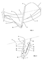
- FIG. 1 An exemplary embodiment shown in Fig. 1 is a rotating blade that is configured and arranged to rotate around a rotational axis 2, which in the radial direction forms a longitudinal plain.
- the blade comprises a leading edge 7, trailing edge 8 a pressure surface 5 and a suction surface 6.
- the leading edge 7 is curved along a radial height 3 in a circumferential direction 4 relative to the rotational axis 2, and additionally comprises a sheath 10 that covers a portion of the core 11 of the blade and forms at least a portion of the leading edge 7.
- a blade comprises a sheath 10 that covers a portion of the core 11 of the blade and forms at least a portion of a curved trailing edge 8 of the blade wherein the curvature is along a radial height 3 of the blade in a circumferential direction 4.
- the sheath 10 including a suction portion 22 and a pressure portion 12 that each project from a head portion 20 of the blade so as to form part of the suction surface 6 and pressure surface 5 respectively.
- maximising the contact surface area of the sheath 10 on the pressure surface 5 maximises the adhesion surface between the sheath 10 and the body of the blade, which is enhanced by the inner surface of the pressure portion 12 and the inner surface of the suction portion 22 forming a cavity between themselves that is shaped to enable the insertion of a portion of the core 11 therein.
- the sheath 10 is configured to protect the blade body from erosion in a circumferential curved edge region of the blade by forming part of an edge 7, 8 region of the blade.
- the sheath 10 is configured such that the sheath 10 has a fixed assembly angle on the core 11 over the radial height 3 of the sheath 10.
- this is achieved by the pressure inner surface 14 of the pressure portion 12 of the sheath 10 being configured such that at any circumferential section of the blade, a tangential vector 18 projected from any point of the pressure inner surface 14 forms a first angle 16 with the rotational axis 2.
- This first angle 16 does not vary over the radial height 3 of the sheath 10. That is, the first angle 16 is uniform over the entire radial height 3 of the sheath 10.
- the first angle 16 is the assembly angle 16 and as a result defines the assembly direction of the sheath 10 on the core 11.
- the length of the pressure portion 12 varies with radial height 3 due to the curvature of the blade resulting in a change in angle of the pressure surface 5 relative to the rotational axis 2.
- the suction inner surface 24 extends from the head portion 20 either parallel to or divergent from the pressure side inner surface 14.
- a tangential vector 28 to the suction inner surface 24 forms a second angle 26 with the tangent line 18 of the pressure inner surface 14.
- the suction inner surface 24 may be either straight or curved.
- the disclosure has been herein shown and described in what is conceived to be the most practical exemplary embodiments, the present disclosure can be embodied in other specific forms.
- the pressure inner surface 14 has a fixed first angle 16
- the fixed suction inner surface 24 may alternatively have the fixed angle rather or in addition to the pressure inner surface 14.
- the pressure inner surface 14 is shown for each circumferential cross-section to be straight, it is possible to provide the inner surface 14 with an outwardly flaring inner surface in which one point of the pressure inner surface 14 defines the assemble angle 16.
Landscapes
- Engineering & Computer Science (AREA)
- Chemical & Material Sciences (AREA)
- Materials Engineering (AREA)
- Mechanical Engineering (AREA)
- General Engineering & Computer Science (AREA)
- Composite Materials (AREA)
- Architecture (AREA)
- Turbine Rotor Nozzle Sealing (AREA)
- Structures Of Non-Positive Displacement Pumps (AREA)
Priority Applications (1)
| Application Number | Priority Date | Filing Date | Title |
|---|---|---|---|
| EP15187411.2A EP3020925A1 (fr) | 2014-10-29 | 2015-09-29 | Pale de rotor avec protection des bords |
Applications Claiming Priority (2)
| Application Number | Priority Date | Filing Date | Title |
|---|---|---|---|
| EP14190777 | 2014-10-29 | ||
| EP15187411.2A EP3020925A1 (fr) | 2014-10-29 | 2015-09-29 | Pale de rotor avec protection des bords |
Publications (1)
| Publication Number | Publication Date |
|---|---|
| EP3020925A1 true EP3020925A1 (fr) | 2016-05-18 |
Family
ID=51868020
Family Applications (1)
| Application Number | Title | Priority Date | Filing Date |
|---|---|---|---|
| EP15187411.2A Withdrawn EP3020925A1 (fr) | 2014-10-29 | 2015-09-29 | Pale de rotor avec protection des bords |
Country Status (4)
| Country | Link |
|---|---|
| US (1) | US9803483B2 (fr) |
| EP (1) | EP3020925A1 (fr) |
| JP (1) | JP2016089832A (fr) |
| CN (1) | CN105569739B (fr) |
Families Citing this family (3)
| Publication number | Priority date | Publication date | Assignee | Title |
|---|---|---|---|---|
| CN109071006B (zh) * | 2017-12-26 | 2022-04-08 | 深圳市大疆创新科技有限公司 | 螺旋桨、动力组件及飞行器 |
| CN111828386B (zh) * | 2019-04-16 | 2022-01-28 | 中国航发商用航空发动机有限责任公司 | 组合式风扇叶片 |
| US11988103B2 (en) * | 2021-10-27 | 2024-05-21 | General Electric Company | Airfoils for a fan section of a turbine engine |
Citations (10)
| Publication number | Priority date | Publication date | Assignee | Title |
|---|---|---|---|---|
| JPS6263101A (ja) * | 1985-09-13 | 1987-03-19 | Toshiba Corp | タ−ビン羽根 |
| US4795313A (en) * | 1986-05-28 | 1989-01-03 | Alsthom | Protective tip for a titanium blade and a method of brazing such a tip |
| US5782607A (en) | 1996-12-11 | 1998-07-21 | United Technologies Corporation | Replaceable ceramic blade insert |
| US6447254B1 (en) * | 2001-05-18 | 2002-09-10 | Sikorsky Aircraft Corporation | Low dieletric constant erosion resistant material |
| US7896221B2 (en) | 2009-04-22 | 2011-03-01 | Rolls-Royce Plc | Method of manufacturing an aerofoil |
| EP2348192A2 (fr) * | 2010-01-26 | 2011-07-27 | United Technologies Corporation | Gaine d'aube de soufflante |
| EP2362066A2 (fr) * | 2010-02-26 | 2011-08-31 | United Technologies Corporation | Aube de soufflante creuse |
| EP2469025A2 (fr) * | 2010-12-21 | 2012-06-27 | United Technologies Corporation | Procédé de fixation d'une gaine à une aube |
| US20120255176A1 (en) * | 2009-12-23 | 2012-10-11 | Snecma | Method for producing a metal reinforcement for a turbine engine blade |
| US20140013599A1 (en) * | 2012-07-11 | 2014-01-16 | Pratt & Whitney | Method of Manufacturing Fan Blade Shields |
Family Cites Families (9)
| Publication number | Priority date | Publication date | Assignee | Title |
|---|---|---|---|---|
| JPS61164002A (ja) * | 1985-01-17 | 1986-07-24 | Toshiba Corp | タ−ビン羽根 |
| GB2293631B (en) * | 1994-09-30 | 1998-09-09 | Gen Electric | Composite fan blade trailing edge reinforcement |
| US5908285A (en) * | 1995-03-10 | 1999-06-01 | United Technologies Corporation | Electroformed sheath |
| FR2867096B1 (fr) * | 2004-03-08 | 2007-04-20 | Snecma Moteurs | Procede de fabrication d'un bord d'attaque ou de fuite de renforcement pour une aube de soufflante |
| JP2011007093A (ja) * | 2009-06-25 | 2011-01-13 | Hitachi Ltd | タービン動翼 |
| US9650897B2 (en) * | 2010-02-26 | 2017-05-16 | United Technologies Corporation | Hybrid metal fan blade |
| US20110229334A1 (en) * | 2010-03-16 | 2011-09-22 | United Technologies Corporation | Composite leading edge sheath and dovetail root undercut |
| FR2993942B1 (fr) * | 2012-07-24 | 2017-03-24 | Snecma | Aube composite de turbomachine a renfort structurel |
| US20160010470A1 (en) * | 2013-03-14 | 2016-01-14 | United Technologies Corporation | Frangible Sheath for a Fan Blade of a Gas Turbine Engine |
-
2015
- 2015-09-29 EP EP15187411.2A patent/EP3020925A1/fr not_active Withdrawn
- 2015-10-28 JP JP2015211515A patent/JP2016089832A/ja not_active Ceased
- 2015-10-28 US US14/925,059 patent/US9803483B2/en not_active Expired - Fee Related
- 2015-10-29 CN CN201510714500.6A patent/CN105569739B/zh not_active Expired - Fee Related
Patent Citations (10)
| Publication number | Priority date | Publication date | Assignee | Title |
|---|---|---|---|---|
| JPS6263101A (ja) * | 1985-09-13 | 1987-03-19 | Toshiba Corp | タ−ビン羽根 |
| US4795313A (en) * | 1986-05-28 | 1989-01-03 | Alsthom | Protective tip for a titanium blade and a method of brazing such a tip |
| US5782607A (en) | 1996-12-11 | 1998-07-21 | United Technologies Corporation | Replaceable ceramic blade insert |
| US6447254B1 (en) * | 2001-05-18 | 2002-09-10 | Sikorsky Aircraft Corporation | Low dieletric constant erosion resistant material |
| US7896221B2 (en) | 2009-04-22 | 2011-03-01 | Rolls-Royce Plc | Method of manufacturing an aerofoil |
| US20120255176A1 (en) * | 2009-12-23 | 2012-10-11 | Snecma | Method for producing a metal reinforcement for a turbine engine blade |
| EP2348192A2 (fr) * | 2010-01-26 | 2011-07-27 | United Technologies Corporation | Gaine d'aube de soufflante |
| EP2362066A2 (fr) * | 2010-02-26 | 2011-08-31 | United Technologies Corporation | Aube de soufflante creuse |
| EP2469025A2 (fr) * | 2010-12-21 | 2012-06-27 | United Technologies Corporation | Procédé de fixation d'une gaine à une aube |
| US20140013599A1 (en) * | 2012-07-11 | 2014-01-16 | Pratt & Whitney | Method of Manufacturing Fan Blade Shields |
Also Published As
| Publication number | Publication date |
|---|---|
| US9803483B2 (en) | 2017-10-31 |
| CN105569739A (zh) | 2016-05-11 |
| JP2016089832A (ja) | 2016-05-23 |
| US20160123158A1 (en) | 2016-05-05 |
| CN105569739B (zh) | 2020-03-03 |
Similar Documents
| Publication | Publication Date | Title |
|---|---|---|
| EP2256296B1 (fr) | Aube de soufflante renforcée en composite et soufflante associée | |
| EP2667019B1 (fr) | Bande de bord de fuite | |
| US9803483B2 (en) | Rotor blade with edge protection | |
| EP2378079A2 (fr) | Gaine composite de bord d'attaque et entaille d'ancrage de queue d'aronde | |
| US9587497B2 (en) | Turbine airfoil of composite material and method of manufacturing thereof | |
| EP2532880B1 (fr) | Pale de rotor pour éolienne | |
| CN108026777B (zh) | 包括折叠前缘防护件的叶片及其制造方法 | |
| EP2697506B1 (fr) | Pale d'éolienne comprenant un moyen de chauffage résistif | |
| CN105221357B (zh) | 风力涡轮、风力涡轮转子叶片、叶片根部及其根部衬套 | |
| CN109642541A (zh) | 风力涡轮机叶片上的涡流发生器装置的真空辅助安装 | |
| ES2853300T3 (es) | Pala de turbina eólica, turbina eólica y método para producir una pala de turbina eólica | |
| BR112017005337B1 (pt) | Processo de fabricação para fabricar uma blindagem de borda dianteira, blindagem de borda dianteira, lâmina, e, turbofan | |
| JP4390026B2 (ja) | 複合材翼 | |
| JP5737739B2 (ja) | 船舶用プロペラ | |
| CN105637182B (zh) | 涡轮叶片和燃气轮机 | |
| SE533559C2 (sv) | Sliphjul | |
| CN108883588A (zh) | 用于风轮机叶片的嵌入元件 | |
| CN107849924A (zh) | 包括由复合材料制成的叶片主体和前缘护罩的叶片 | |
| KR102197433B1 (ko) | 풍력 터빈 블레이드, 풍력 터빈 로터 및 풍력 터빈 발전 장치 | |
| US20150017010A1 (en) | Turbomachine blade comprising an insert protecting the blade tip | |
| EP3090134B1 (fr) | Aube de ventilateur avec orifices passants à travers le pied de l'aube | |
| GB2489222A (en) | Bladed rotor with annulus filler | |
| KR20230065250A (ko) | 풍력 터빈 블레이드를 위한 리딩 에지 보호 | |
| KR101274677B1 (ko) | 제어관을 갖는 로터 블레이드 |
Legal Events
| Date | Code | Title | Description |
|---|---|---|---|
| PUAI | Public reference made under article 153(3) epc to a published international application that has entered the european phase |
Free format text: ORIGINAL CODE: 0009012 |
|
| AK | Designated contracting states |
Kind code of ref document: A1 Designated state(s): AL AT BE BG CH CY CZ DE DK EE ES FI FR GB GR HR HU IE IS IT LI LT LU LV MC MK MT NL NO PL PT RO RS SE SI SK SM TR |
|
| AX | Request for extension of the european patent |
Extension state: BA ME |
|
| RAP1 | Party data changed (applicant data changed or rights of an application transferred) |
Owner name: GENERAL ELECTRIC TECHNOLOGY GMBH |
|
| STAA | Information on the status of an ep patent application or granted ep patent |
Free format text: STATUS: REQUEST FOR EXAMINATION WAS MADE |
|
| 17P | Request for examination filed |
Effective date: 20161118 |
|
| RBV | Designated contracting states (corrected) |
Designated state(s): AL AT BE BG CH CY CZ DE DK EE ES FI FR GB GR HR HU IE IS IT LI LT LU LV MC MK MT NL NO PL PT RO RS SE SI SK SM TR |
|
| STAA | Information on the status of an ep patent application or granted ep patent |
Free format text: STATUS: EXAMINATION IS IN PROGRESS |
|
| 17Q | First examination report despatched |
Effective date: 20180430 |
|
| STAA | Information on the status of an ep patent application or granted ep patent |
Free format text: STATUS: EXAMINATION IS IN PROGRESS |
|
| STAA | Information on the status of an ep patent application or granted ep patent |
Free format text: STATUS: EXAMINATION IS IN PROGRESS |
|
| RAP3 | Party data changed (applicant data changed or rights of an application transferred) |
Owner name: GENERAL ELECTRIC TECHNOLOGY GMBH |
|
| STAA | Information on the status of an ep patent application or granted ep patent |
Free format text: STATUS: THE APPLICATION IS DEEMED TO BE WITHDRAWN |
|
| 18D | Application deemed to be withdrawn |
Effective date: 20220401 |