EP3020600A1 - Vehicle seat - Google Patents
Vehicle seat Download PDFInfo
- Publication number
- EP3020600A1 EP3020600A1 EP15193851.1A EP15193851A EP3020600A1 EP 3020600 A1 EP3020600 A1 EP 3020600A1 EP 15193851 A EP15193851 A EP 15193851A EP 3020600 A1 EP3020600 A1 EP 3020600A1
- Authority
- EP
- European Patent Office
- Prior art keywords
- seat
- width direction
- seatback
- main section
- seat width
- Prior art date
- Legal status (The legal status is an assumption and is not a legal conclusion. Google has not performed a legal analysis and makes no representation as to the accuracy of the status listed.)
- Granted
Links
- 239000000463 material Substances 0.000 claims description 14
- 230000008878 coupling Effects 0.000 description 4
- 238000010168 coupling process Methods 0.000 description 4
- 238000005859 coupling reaction Methods 0.000 description 4
- 230000000694 effects Effects 0.000 description 4
- 239000004744 fabric Substances 0.000 description 3
- 238000003825 pressing Methods 0.000 description 3
- 230000035807 sensation Effects 0.000 description 3
- 101001108245 Cavia porcellus Neuronal pentraxin-2 Proteins 0.000 description 2
- 238000006243 chemical reaction Methods 0.000 description 2
- 239000010985 leather Substances 0.000 description 2
- 238000000465 moulding Methods 0.000 description 2
- 229920005989 resin Polymers 0.000 description 2
- 239000011347 resin Substances 0.000 description 2
- 230000000284 resting effect Effects 0.000 description 2
- 229920005830 Polyurethane Foam Polymers 0.000 description 1
- 239000000853 adhesive Substances 0.000 description 1
- 230000001070 adhesive effect Effects 0.000 description 1
- 210000001217 buttock Anatomy 0.000 description 1
- 229920001971 elastomer Polymers 0.000 description 1
- 238000005516 engineering process Methods 0.000 description 1
- 238000005187 foaming Methods 0.000 description 1
- 238000004519 manufacturing process Methods 0.000 description 1
- 238000012986 modification Methods 0.000 description 1
- 230000004048 modification Effects 0.000 description 1
- 239000011496 polyurethane foam Substances 0.000 description 1
- 229920005749 polyurethane resin Polymers 0.000 description 1
- 239000000725 suspension Substances 0.000 description 1
- 210000000689 upper leg Anatomy 0.000 description 1
Images


Classifications
-
- B—PERFORMING OPERATIONS; TRANSPORTING
- B60—VEHICLES IN GENERAL
- B60N—SEATS SPECIALLY ADAPTED FOR VEHICLES; VEHICLE PASSENGER ACCOMMODATION NOT OTHERWISE PROVIDED FOR
- B60N2/00—Seats specially adapted for vehicles; Arrangement or mounting of seats in vehicles
- B60N2/70—Upholstery springs ; Upholstery
- B60N2/72—Attachment or adjustment thereof
-
- B—PERFORMING OPERATIONS; TRANSPORTING
- B60—VEHICLES IN GENERAL
- B60N—SEATS SPECIALLY ADAPTED FOR VEHICLES; VEHICLE PASSENGER ACCOMMODATION NOT OTHERWISE PROVIDED FOR
- B60N2/00—Seats specially adapted for vehicles; Arrangement or mounting of seats in vehicles
- B60N2/64—Back-rests or cushions
- B60N2/643—Back-rests or cushions shape of the back-rests
-
- B—PERFORMING OPERATIONS; TRANSPORTING
- B60—VEHICLES IN GENERAL
- B60N—SEATS SPECIALLY ADAPTED FOR VEHICLES; VEHICLE PASSENGER ACCOMMODATION NOT OTHERWISE PROVIDED FOR
- B60N2/00—Seats specially adapted for vehicles; Arrangement or mounting of seats in vehicles
- B60N2/90—Details or parts not otherwise provided for
- B60N2/986—Side-rests
Definitions
- the present invention relates to a vehicle seat.
- JP-A Japanese Patent Application Laid-Open ( JP-A) No. 2013-244239 describes a vehicle seat configured to lessen a pressing sensation on the region of both scapulae of a seated occupant, and to fit a seat face to a region of the back between the scapulae while accommodating differences in physical build and seating posture between seated occupants.
- the vehicle seat described in this document includes a first slab pad formed using a softer material than that of a seatback pad (molded pad), provided at a seat width direction intermediate portion of a front face of the seatback pad.
- second slab pads formed using a softer material than that of the seatback pad are provided on both seat width direction side portions of the first slab pad (at portions supporting both scapulae).
- the first slab pad projects out further to the seat front side than the second slab pads, thereby enabling a pressing sensation on both scapulae of the seated occupant to be lessened, and enabling the seat face to fit to the region of the back between the scapulae while accommodating differences in physical build and seating posture between seated occupants.
- JP-A No. 2013-244239 is useful from the perspectives of lessening the pressing sensation on the region of both scapulae of the seated occupant, and of fitting the seat face to the region of the back between the scapulae while accommodating differences in physical build and seating posture between seated occupants, there remains room for improvement from the perspective of improving holding properties with respect to the seated occupant leaning in the seat width direction when lateral G force arises.
- an object of the present invention is to obtain a vehicle seat capable of improving holding properties with respect to a seated occupant leaning in the seat width direction when lateral G force arises.
- a vehicle seat includes: a seatback frame that forms a framework of a seatback that supports the back of a seated occupant; and a seatback pad that is attached to the seatback frame, and that includes a pair of left and right side support sections respectively disposed at both seat width direction end portions of the seatback pad, a main section disposed between the pair of left and right side support sections, and soft angled sections that are provided at seat front side end portions at both seat width direction end portions of the main section, that are softer than a seat width direction intermediate portion of the main section, and that are angled such that seat front side faces of the soft angled sections are disposed further toward the seat front side on progression toward the seat width direction outer side.
- the side support sections, the main section, and the soft angled sections of the seatback pad deform.
- the seat front side faces of the soft angled sections namely the faces of the soft angled sections on the side of the seated occupant, are angled toward the seat front side on progression toward the seat width direction outer side. Accordingly, when the soft angled sections deform so as to stretch out toward the seat width direction outer side due to the seated occupant leaning toward the seat width direction outer side, tension rapidly arises in the occupant side faces of the soft angled sections (the occupant side faces on the soft angled sections are rapidly pulled taut). This thereby enables the seated occupant to rapidly obtain a reaction force from the soft angled sections, thus enabling improved holding properties with respect to the seated occupant leaning in the seat width direction when lateral G force arises.
- a vehicle seat according to a second aspect of the present invention is the vehicle seat of the first aspect, wherein: the seatback pad is covered with a covering material; and the coefficient of friction of a surface of the covering material at a location covering the soft angled section is set higher than the coefficient of friction of a surface of the covering material at a location covering the seat width direction intermediate portion of the main section.
- setting the coefficient of friction of the covering material as described above enables a further improvement in the holding properties with respect to the seated occupant leaning in the seat width direction when lateral G force arises.
- a vehicle seat according to a third aspect of the present invention is the vehicle seat of either the first aspect or the second aspect, wherein: the seatback pad is formed with first recessed grooves opening toward the seat front side between the side support sections and the main section, and is formed with second recessed grooves opening toward the seat front side on both seat width direction sides of the main section and further to the seat width direction inner side than the first recessed grooves: and the soft angled sections are joined to seat front side end faces of the main section at locations between the first recessed grooves and the second recessed grooves.
- the seat front side end faces of the main section at locations between the first recessed grooves and the second recessed grooves configure joint faces of the soft angled sections, thereby enabling easy positioning of the soft angled sections in the seat width direction.
- the vehicle seat according to the present invention exhibits the excellent advantageous effect of enabling an improvement in the holding properties with respect to the seated occupant leaning in the seat width direction when lateral G force arises.
- a vehicle seat according to an exemplary embodiment of the present invention, with reference to Fig. 1 to Fig. 3 .
- reference to the front-rear, left-right, and up-down directions indicates the front-rear, left-right, and up-down directions from the perspective of an occupant sitting in the vehicle seat.
- the arrow FR indicates the front direction
- the arrow UP indicates the upward direction
- the arrow RH indicates the right direction
- the arrow LH indicates the left direction as appropriate.
- the arrow RH and the arrow LH correspond to the seat width direction.
- a vehicle seat 10 of the present exemplary embodiment is employed as a driving seat or a front passenger seat.
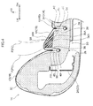
- the vehicle seat 10 includes a seat cushion 12 that supports the buttocks and thighs of an occupant P, a seatback 14 that supports the back of the occupant P, and a headrest 16 that supports the head of the occupant P.
- the seatback 14 is reclinably attached to a rear end portion of the seat cushion 12, and as illustrated in Fig. 1 , the seatback 14 is configured by attaching a seatback pad 20 covered with a covering material 18 to a seatback frame 22.
- the seatback frame 22 that configures framework of the seatback 14 includes a pair of side frames 24 extending in the seat up-down direction at seat width direction right side and left side end portions inside the seatback 14, and an upper frame, not illustrated in the drawings, connecting together upper ends of the pair of side frames 24 along the seat width direction.
- the side frames 24 are substantially formed with U-shaped cross-sections opening toward the seat width direction inner side in plan view of the seat.
- a seatback spring 26 spans between the left and right side frames 24.
- the seatback pad 20 includes a seatback pad body 28 formed by injecting a foamable resin material such as polyurethane resin into a specific mold and foaming inside the mold, and soft angled sections 30 that are formed from polyurethane foam slabs and joined to the seatback pad body 28.
- a foamable resin material such as polyurethane resin
- the seatback pad body 28 includes a pair of left and right side support sections 32 respectively disposed at both seat width direction end portions of the seatback pad body 28, and a main section 34 disposed between the pair of left and right side support sections 32.
- the side support sections 32 are formed projecting out toward the seat front side with respect to the main section 34, thus suppressing seat width direction movement of the occupant P sitting in the vehicle seat 10.
- first recessed grooves 36 opening toward the seat front side are formed at boundaries between the side support sections 32 and the main section 34.
- second recessed grooves 38 opening toward the seat front side are formed on both seat width direction sides of the main section 34, further to the seat width direction inner side than the first recessed grooves 36.
- Seat front side end faces of the main section 34 at locations between the respective first recessed grooves 36 and second recessed grooves 38 configure soft angled section joint faces 34A, to which the soft angled sections 30, described later, are joined.
- the soft angled sections 30 are formed using a softer material than that of the seatback pad body 28, and the soft angled sections 30 are formed with substantially triangular cross-sections in plan view cross-section.
- Seat rear side end faces of the soft angled sections 30 configure joint faces 30A that are joined to the soft angled section joint faces 34A of the seatback pad body 28 using an adhesive or the like.
- seat front side end faces of the soft angled sections 30, namely end faces on the occupant P side of the soft angled sections 30, configure angled faces 30B that are angled toward the seat front side on progression toward the seat width direction outer side.
- the soft angled sections 30 In a joined state of the soft angled sections 30 to the seatback pad body 28, the soft angled sections 30 project out further toward the seat front side than a seat width direction intermediate portion 34B of the main section 34.
- the soft angled sections 30 are disposed at positions facing the scapulae of the occupant P sitting in the vehicle seat 10 along the seat front-rear direction.
- the seat width direction positions of the soft angled sections 30 are set in consideration of the positions of the scapulae of occupants P with physical builds corresponding to an AM50 dummy and a JF05 dummy, in a seated state with standard posture in the vehicle seat 10 that is set in a standard usage state.
- the occupant P labelled P1 is an occupant with a physical build corresponding to an AM50 dummy
- the occupant P labelled P2 is an occupant with a physical build corresponding to a JF05 dummy.
- the covering material 18 covering the seatback pad 20 described above is made from fabric or leather, and the covering material 18 of the present exemplary embodiment is formed by appropriately stitching together a main section cover 40 that covers a seat width direction intermediate portion of the main section 34, side support section covers 42 that cover the side support sections 32, and soft angled section covers 44 that cover the soft angled sections 30. Specifically, seat width direction inner side end portions of the side support section covers 42 are stitched together with seat width direction outer side end portions of the soft angled section covers 44.
- One end of a coupling member (suspension cloth) 46 is stitched to each such stitching location A1, and the other end of the coupling member 46 is coupled using hog rings 50 to an insert wire 48 formed by insert molding to the seatback pad body 28 at a closed end portion of each of the first recessed grooves 36.
- Seat width direction outer side end portions of the main section cover 40 are stitched to seat width direction inner side end portions of the soft angled section covers 44.
- One end of a coupling member 52 is stitched to each such stitching location A2, and the other end of the coupling member 52 is coupled using hog rings 56 to an insert wire 54 formed by insert molding to the seatback pad body 28 at a closed end portion of each of the second recessed grooves 38.
- the coefficient of friction of the surfaces (faces on the occupant P side) of the soft angled section covers 44 is set higher than the coefficient of friction of the surface (face on the occupant P side) of the main section cover 40.
- the coefficients of friction can be set as described above by making the main section cover 40 out of leather, and making the soft angled section covers 44 out of fabric.
- the coefficients of friction can also be set as described above by applying a surface finish employing a resin, rubber, or the like with a high coefficient of friction to the surfaces (faces on the occupant P side) of the soft angled section covers 44.
- the side support sections 32, the main section 34, and the soft angled sections 30 of the seatback pad 20 deform so as to conform to the shape of the occupant P illustrated in Fig. 1 and Fig. 3 .
- the seat front side faces of the soft angled sections 30, namely the faces of the soft angled sections 30 on the side of the seated occupant P configure the angled faces 30B that are angled toward the seat front side on progression toward the seat width direction outer side. Accordingly, when the soft angled sections 30 deform so as to stretch out toward the seat width direction outer side due to the seated occupant P leaning toward the seat width direction outer side, tension rapidly arises in the angled faces 30B of the soft angled sections 30 (the angled faces 30B of the soft angled sections 30 are rapidly pulled taut). This thereby enables the seated occupant P to rapidly obtain a reaction force from the soft angled sections 30, thus enabling improved holding properties with respect to the seated occupant P leaning in the seat width direction.
- the coefficient of friction of the occupant P side faces of the soft angled section covers 44 is set higher than the coefficient of friction of the occupant P side face of the main section cover 40, thereby enabling a further improvement to the holding properties with respect to the seated occupant P leaning in the seat width direction.
- the seat front side end faces of the main section 34 of the seatback pad body 28 at locations between the first recessed grooves 36 and the second recessed grooves 38 configure the soft angled section joint faces 34A to which the soft angled sections 30 are joined, thereby enabling easy positioning of the soft angled sections 30 in the seat width direction.
- soft angled sections 30, formed with substantially triangular cross-sections in plan view cross-section are attached to the seatback pad body 28; however, the present invention is not limited thereto.
- soft angled sections 58, 60 formed with substantially trapezoidal cross-sections in plan view cross-section may be attached to the seatback pad body 28, or as illustrated in Fig. 6 , soft angled sections 62 formed with substantially pentagonal cross-sections in plan view cross-section may be attached to the seatback pad body 28.
- the angle of the angled faces 30B can be set larger with respect to the seat width direction, while securing the rigidity of seat width direction outer side end portions of the soft angled sections 58.
- the soft angled sections 60, 62 illustrated in Fig. 5 and Fig. 6 the soft angled sections 60, 62 can be made to project out further with respect to the seat width direction intermediate portion 34B of the main section 34, while securing rigidity of seat width direction outer side end portions of the soft angled sections 60, 62.
- an integral seatback pad including soft angled sections configured softer than the seat width direction intermediate portion 34B of the main section 34 may be formed by setting the density of locations corresponding to the soft angled sections 30 lower than the density of the seat width direction intermediate portion 34B of the main section 34.
- the hardness of these locations may also be set softer than the seat width direction intermediate portion 34B of the main section 34 by, for example, the addition of grooves or the like at locations corresponding to the soft angled sections 30.
Landscapes
- Engineering & Computer Science (AREA)
- Aviation & Aerospace Engineering (AREA)
- Transportation (AREA)
- Mechanical Engineering (AREA)
- Seats For Vehicles (AREA)
Abstract
Description
- The present invention relates to a vehicle seat.
- Japanese Patent Application Laid-Open (
JP-A) No. 2013-244239 - Moreover, second slab pads formed using a softer material than that of the seatback pad are provided on both seat width direction side portions of the first slab pad (at portions supporting both scapulae). The first slab pad projects out further to the seat front side than the second slab pads, thereby enabling a pressing sensation on both scapulae of the seated occupant to be lessened, and enabling the seat face to fit to the region of the back between the scapulae while accommodating differences in physical build and seating posture between seated occupants.
- However, while the technology described in
JP-A No. 2013-244239 - In consideration of the above circumstances, an object of the present invention is to obtain a vehicle seat capable of improving holding properties with respect to a seated occupant leaning in the seat width direction when lateral G force arises.
- A vehicle seat according to a first aspect of the present invention includes: a seatback frame that forms a framework of a seatback that supports the back of a seated occupant; and a seatback pad that is attached to the seatback frame, and that includes a pair of left and right side support sections respectively disposed at both seat width direction end portions of the seatback pad, a main section disposed between the pair of left and right side support sections, and soft angled sections that are provided at seat front side end portions at both seat width direction end portions of the main section, that are softer than a seat width direction intermediate portion of the main section, and that are angled such that seat front side faces of the soft angled sections are disposed further toward the seat front side on progression toward the seat width direction outer side.
- In the vehicle seat according to the first aspect, when the occupant rests against the seatback such that the back of the occupant presses the seatback, load input from the occupant is transmitted through the seatback pad to the seatback frame. The back of the occupant is thus supported by the seatback. In a state in which the occupant is resting against the seatback, the side support sections, the main section, and the soft angled sections of the seatback pad deform.
- In the vehicle seat according to the first aspect, the seat front side faces of the soft angled sections, namely the faces of the soft angled sections on the side of the seated occupant, are angled toward the seat front side on progression toward the seat width direction outer side. Accordingly, when the soft angled sections deform so as to stretch out toward the seat width direction outer side due to the seated occupant leaning toward the seat width direction outer side, tension rapidly arises in the occupant side faces of the soft angled sections (the occupant side faces on the soft angled sections are rapidly pulled taut). This thereby enables the seated occupant to rapidly obtain a reaction force from the soft angled sections, thus enabling improved holding properties with respect to the seated occupant leaning in the seat width direction when lateral G force arises.
- A vehicle seat according to a second aspect of the present invention is the vehicle seat of the first aspect, wherein: the seatback pad is covered with a covering material; and the coefficient of friction of a surface of the covering material at a location covering the soft angled section is set higher than the coefficient of friction of a surface of the covering material at a location covering the seat width direction intermediate portion of the main section.
- In the vehicle seat of the second aspect, setting the coefficient of friction of the covering material as described above enables a further improvement in the holding properties with respect to the seated occupant leaning in the seat width direction when lateral G force arises.
- A vehicle seat according to a third aspect of the present invention is the vehicle seat of either the first aspect or the second aspect, wherein: the seatback pad is formed with first recessed grooves opening toward the seat front side between the side support sections and the main section, and is formed with second recessed grooves opening toward the seat front side on both seat width direction sides of the main section and further to the seat width direction inner side than the first recessed grooves: and the soft angled sections are joined to seat front side end faces of the main section at locations between the first recessed grooves and the second recessed grooves.
- In the vehicle seat according to the third aspect, the seat front side end faces of the main section at locations between the first recessed grooves and the second recessed grooves configure joint faces of the soft angled sections, thereby enabling easy positioning of the soft angled sections in the seat width direction.
- The vehicle seat according to the present invention exhibits the excellent advantageous effect of enabling an improvement in the holding properties with respect to the seated occupant leaning in the seat width direction when lateral G force arises.
- Embodiments of the present invention will be described in detail based on the following figures, wherein:
-
Fig. 1 is a plan view cross-section illustrating a cross-section of a seatback taken along line 1-1 inFig. 2 ; -
Fig. 2 is a side view illustrating a vehicle seat and an occupant seated in the vehicle seat; -
Fig. 3 is an enlarged plan view cross-section illustrating an enlarged end portion on the left side of a seatback; -
Fig. 4 is an enlarged plan view cross-section corresponding toFig. 3 , illustrating a seatback according to a first modified example; -
Fig. 5 is an enlarged plan view cross-section corresponding toFig. 3 , illustrating a seatback according to a second modified example; and -
Fig. 6 is an enlarged plan view cross-section corresponding toFig. 3 , illustrating a seatback according to a third modified example. - Explanation follows regarding a vehicle seat according to an exemplary embodiment of the present invention, with reference to
Fig. 1 to Fig. 3 . In the following explanation, reference to the front-rear, left-right, and up-down directions indicates the front-rear, left-right, and up-down directions from the perspective of an occupant sitting in the vehicle seat. In each of the drawings, the arrow FR indicates the front direction, the arrow UP indicates the upward direction, the arrow RH indicates the right direction, and the arrow LH indicates the left direction as appropriate. The arrow RH and the arrow LH correspond to the seat width direction. - As illustrated in
Fig. 2 , avehicle seat 10 of the present exemplary embodiment is employed as a driving seat or a front passenger seat. Thevehicle seat 10 includes aseat cushion 12 that supports the buttocks and thighs of an occupant P, aseatback 14 that supports the back of the occupant P, and aheadrest 16 that supports the head of the occupant P. - The
seatback 14 is reclinably attached to a rear end portion of theseat cushion 12, and as illustrated inFig. 1 , theseatback 14 is configured by attaching aseatback pad 20 covered with a coveringmaterial 18 to aseatback frame 22. - The
seatback frame 22 that configures framework of theseatback 14 includes a pair ofside frames 24 extending in the seat up-down direction at seat width direction right side and left side end portions inside theseatback 14, and an upper frame, not illustrated in the drawings, connecting together upper ends of the pair ofside frames 24 along the seat width direction. Theside frames 24 are substantially formed with U-shaped cross-sections opening toward the seat width direction inner side in plan view of the seat. A seatback spring 26 spans between the left andright side frames 24. - The
seatback pad 20 includes aseatback pad body 28 formed by injecting a foamable resin material such as polyurethane resin into a specific mold and foaming inside the mold, and softangled sections 30 that are formed from polyurethane foam slabs and joined to theseatback pad body 28. - The
seatback pad body 28 includes a pair of left and rightside support sections 32 respectively disposed at both seat width direction end portions of theseatback pad body 28, and amain section 34 disposed between the pair of left and rightside support sections 32. Theside support sections 32 are formed projecting out toward the seat front side with respect to themain section 34, thus suppressing seat width direction movement of the occupant P sitting in thevehicle seat 10. As illustrated inFig. 3 , firstrecessed grooves 36 opening toward the seat front side are formed at boundaries between theside support sections 32 and themain section 34. Moreover, secondrecessed grooves 38 opening toward the seat front side are formed on both seat width direction sides of themain section 34, further to the seat width direction inner side than the firstrecessed grooves 36. Seat front side end faces of themain section 34 at locations between the respective firstrecessed grooves 36 and secondrecessed grooves 38 configure soft angledsection joint faces 34A, to which the softangled sections 30, described later, are joined. - The soft
angled sections 30 are formed using a softer material than that of theseatback pad body 28, and the softangled sections 30 are formed with substantially triangular cross-sections in plan view cross-section. Seat rear side end faces of the softangled sections 30 configurejoint faces 30A that are joined to the soft angledsection joint faces 34A of theseatback pad body 28 using an adhesive or the like. Moreover, seat front side end faces of the softangled sections 30, namely end faces on the occupant P side of the softangled sections 30, configureangled faces 30B that are angled toward the seat front side on progression toward the seat width direction outer side. In a joined state of the softangled sections 30 to theseatback pad body 28, the softangled sections 30 project out further toward the seat front side than a seat width directionintermediate portion 34B of themain section 34. The softangled sections 30 are disposed at positions facing the scapulae of the occupant P sitting in thevehicle seat 10 along the seat front-rear direction. The seat width direction positions of the softangled sections 30 are set in consideration of the positions of the scapulae of occupants P with physical builds corresponding to an AM50 dummy and a JF05 dummy, in a seated state with standard posture in thevehicle seat 10 that is set in a standard usage state. The occupant P labelled P1 is an occupant with a physical build corresponding to an AM50 dummy, and the occupant P labelled P2 is an occupant with a physical build corresponding to a JF05 dummy. - The covering
material 18 covering theseatback pad 20 described above is made from fabric or leather, and the coveringmaterial 18 of the present exemplary embodiment is formed by appropriately stitching together amain section cover 40 that covers a seat width direction intermediate portion of themain section 34, side support section covers 42 that cover theside support sections 32, and soft angled section covers 44 that cover the softangled sections 30. Specifically, seat width direction inner side end portions of the side support section covers 42 are stitched together with seat width direction outer side end portions of the soft angled section covers 44. One end of a coupling member (suspension cloth) 46 is stitched to each such stitching location A1, and the other end of thecoupling member 46 is coupled usinghog rings 50 to aninsert wire 48 formed by insert molding to theseatback pad body 28 at a closed end portion of each of the first recessedgrooves 36. Seat width direction outer side end portions of themain section cover 40 are stitched to seat width direction inner side end portions of the soft angled section covers 44. One end of acoupling member 52 is stitched to each such stitching location A2, and the other end of thecoupling member 52 is coupled usinghog rings 56 to aninsert wire 54 formed by insert molding to theseatback pad body 28 at a closed end portion of each of the second recessedgrooves 38. - In the present exemplary embodiment, the coefficient of friction of the surfaces (faces on the occupant P side) of the soft angled section covers 44 is set higher than the coefficient of friction of the surface (face on the occupant P side) of the
main section cover 40. As an example, the coefficients of friction can be set as described above by making the main section cover 40 out of leather, and making the soft angled section covers 44 out of fabric. The coefficients of friction can also be set as described above by applying a surface finish employing a resin, rubber, or the like with a high coefficient of friction to the surfaces (faces on the occupant P side) of the soft angled section covers 44. - Next, explanation follows regarding operation and advantageous effects of the present exemplary embodiment.
- As illustrated in
Fig. 1 to Fig. 3 , in thevehicle seat 10 according to the present exemplary embodiment, when the occupant P rests against theseatback 14 such that the back of the occupant P presses theseatback 14, load input from the occupant P is transmitted through theseatback pad 20 to theseatback frame 22. The back of the occupant P is thus supported by theseatback 14. - In a state in which the occupant P is resting against the
seatback 14, theside support sections 32, themain section 34, and the softangled sections 30 of theseatback pad 20 deform so as to conform to the shape of the occupant P illustrated inFig. 1 andFig. 3 . - In the present exemplary embodiment, the seat front side faces of the soft
angled sections 30, namely the faces of the softangled sections 30 on the side of the seated occupant P, configure the angled faces 30B that are angled toward the seat front side on progression toward the seat width direction outer side. Accordingly, when the softangled sections 30 deform so as to stretch out toward the seat width direction outer side due to the seated occupant P leaning toward the seat width direction outer side, tension rapidly arises in the angled faces 30B of the soft angled sections 30 (the angled faces 30B of the softangled sections 30 are rapidly pulled taut). This thereby enables the seated occupant P to rapidly obtain a reaction force from the softangled sections 30, thus enabling improved holding properties with respect to the seated occupant P leaning in the seat width direction. - In the present exemplary embodiment, the coefficient of friction of the occupant P side faces of the soft angled section covers 44 is set higher than the coefficient of friction of the occupant P side face of the
main section cover 40, thereby enabling a further improvement to the holding properties with respect to the seated occupant P leaning in the seat width direction. - In the present exemplary embodiment, the seat front side end faces of the
main section 34 of theseatback pad body 28 at locations between the first recessedgrooves 36 and the second recessedgrooves 38 configure the soft angled section joint faces 34A to which the softangled sections 30 are joined, thereby enabling easy positioning of the softangled sections 30 in the seat width direction. - In the present exemplary embodiment, explanation has been given regarding an example in which the soft
angled sections 30, formed with substantially triangular cross-sections in plan view cross-section, are attached to theseatback pad body 28; however, the present invention is not limited thereto. For example, as illustrated inFig. 4 andFig. 5 , softangled sections seatback pad body 28, or as illustrated inFig. 6 , softangled sections 62 formed with substantially pentagonal cross-sections in plan view cross-section may be attached to theseatback pad body 28. In the softangled sections 58 illustrated inFig. 4 , the angle of the angled faces 30B can be set larger with respect to the seat width direction, while securing the rigidity of seat width direction outer side end portions of the softangled sections 58. In the softangled sections Fig. 5 andFig. 6 , the softangled sections intermediate portion 34B of themain section 34, while securing rigidity of seat width direction outer side end portions of the softangled sections - In the present exemplary embodiment, explanation has been given regarding an example in which the seat front side end faces of the
main section 34 of theseatback pad body 28 at locations between the first recessedgrooves 36 and the second recessedgrooves 38 configure the soft angled section joint faces 34A to which the softangled sections 30 are joined; however, the present invention is not limited thereto. The positions for providing the soft angled section joint faces 34A to which the softangled sections 30 are joined may be set as appropriate in consideration of design factors, manufacturing processes, and the like of the vehicle seat. - In the present exemplary embodiment, explanation has been given regarding an example in which the coefficient of friction of the occupant P side faces of the soft angled section covers 44 is set higher than the coefficient of friction of the occupant P side face of the
main section cover 40; however, the present invention is not limited thereto. Whether or not the coefficient of friction of the occupant P side faces of the soft angled section covers 44 is set higher than the coefficient of friction of the occupant P side face of themain section cover 40 may be set as appropriate in consideration of the holding properties or the like demanded of the vehicle seat. - In the present exemplary embodiment, explanation has been given regarding an example in which the
seatback pad 20 is formed by attaching the softangled sections 30 to theseatback pad body 28; however, the present invention is not limited thereto. For example, an integral seatback pad including soft angled sections configured softer than the seat width directionintermediate portion 34B of themain section 34 may be formed by setting the density of locations corresponding to the softangled sections 30 lower than the density of the seat width directionintermediate portion 34B of themain section 34. The hardness of these locations may also be set softer than the seat width directionintermediate portion 34B of themain section 34 by, for example, the addition of grooves or the like at locations corresponding to the softangled sections 30. - Although one exemplary embodiment of the present invention has been described above, the present invention is not limited to the above, and obviously various other modifications may be implemented within a range not departing from the spirit of the present invention.
Claims (3)
- A vehicle seat, comprising:a seatback frame that forms a framework of a seatback that supports the back of a seated occupant; anda seatback pad that is attached to the seatback frame, and that includes:a pair of left and right side support sections respectively disposed at both seat width direction end portions of the seatback pad,a main section disposed between the pair of left and right side support sections, andsoft angled sections that are provided at seat front side end portions at both seat width direction end portions of the main section, that are softer than a seat width direction intermediate portion of the main section, and that are angled such that seat front side faces of the soft angled sections are disposed further toward the seat front side on progression toward the seat width direction outer side.
- The vehicle seat of claim 1, wherein:the seatback pad is covered with a covering material; andthe coefficient of friction of a surface of the covering material at a location covering the soft angled section is set higher than the coefficient of friction of a surface of the covering material at a location covering the seat width direction intermediate portion of the main section.
- The vehicle seat of either claim 1 or claim 2, wherein:the seatback pad is formed with first recessed grooves opening toward the seat front side between the side support sections and the main section, and is formed with second recessed grooves opening toward the seat front side on both seat width direction sides of the main section and further to the seat width direction inner side than the first recessed grooves; andthe soft angled sections are joined to seat front side end faces of the main section at locations between the first recessed grooves and the second recessed grooves.
Applications Claiming Priority (1)
| Application Number | Priority Date | Filing Date | Title |
|---|---|---|---|
| JP2014230648A JP6098616B2 (en) | 2014-11-13 | 2014-11-13 | Vehicle seat |
Publications (3)
| Publication Number | Publication Date |
|---|---|
| EP3020600A1 true EP3020600A1 (en) | 2016-05-18 |
| EP3020600B1 EP3020600B1 (en) | 2019-05-29 |
| EP3020600B8 EP3020600B8 (en) | 2019-07-24 |
Family
ID=54478662
Family Applications (1)
| Application Number | Title | Priority Date | Filing Date |
|---|---|---|---|
| EP15193851.1A Not-in-force EP3020600B8 (en) | 2014-11-13 | 2015-11-10 | Vehicle seat |
Country Status (4)
| Country | Link |
|---|---|
| US (1) | US9701228B2 (en) |
| EP (1) | EP3020600B8 (en) |
| JP (1) | JP6098616B2 (en) |
| CN (1) | CN105599655A (en) |
Cited By (3)
| Publication number | Priority date | Publication date | Assignee | Title |
|---|---|---|---|---|
| US10052987B2 (en) * | 2016-08-25 | 2018-08-21 | Ts Tech Co., Ltd. | Vehicle seat |
| US10414308B2 (en) * | 2017-03-09 | 2019-09-17 | Toyota Boshoku Kabushiki Kaisha | Vehicle seat and manufacturing method thereof |
| US20200156503A1 (en) * | 2018-11-19 | 2020-05-21 | Hyundai Motor Company | Side extension device for seat of vehicle |
Families Citing this family (4)
| Publication number | Priority date | Publication date | Assignee | Title |
|---|---|---|---|---|
| JP6102901B2 (en) * | 2014-12-19 | 2017-03-29 | トヨタ自動車株式会社 | Vehicle seat |
| KR102633948B1 (en) * | 2018-11-09 | 2024-02-05 | 현대자동차주식회사 | Seat back for vehicle and method for manufacturing the same |
| JP7103587B2 (en) * | 2018-12-27 | 2022-07-20 | 日本発條株式会社 | Vehicle seat |
| JP7101206B2 (en) * | 2020-03-19 | 2022-07-14 | テイ・エス テック株式会社 | Vehicle seat |
Citations (3)
| Publication number | Priority date | Publication date | Assignee | Title |
|---|---|---|---|---|
| JP2005329090A (en) * | 2004-05-21 | 2005-12-02 | Inoac Corp | Vehicle seat |
| EP2623367A1 (en) * | 2010-10-01 | 2013-08-07 | Nissan Motor Co., Ltd | Vehicle seat and stiffness setting method for vehicle seat |
| JP2013244239A (en) | 2012-05-28 | 2013-12-09 | Toyota Boshoku Corp | Vehicle seat |
Family Cites Families (15)
| Publication number | Priority date | Publication date | Assignee | Title |
|---|---|---|---|---|
| US3612607A (en) * | 1969-07-18 | 1971-10-12 | Allied Chemicals Corp | Plastic foam seat construction |
| GB2199492B (en) * | 1987-01-16 | 1990-02-14 | Tachi S Co | Vehicle seat |
| US4924541A (en) * | 1987-03-10 | 1990-05-15 | Jitsuo Inagaki | Bed pad, an automobile seat pad, a pillow or a similar cushionlike item |
| AU614939B2 (en) * | 1987-09-29 | 1991-09-19 | Tachi-S Co., Ltd. | Automotive seat |
| US4835801A (en) * | 1987-11-19 | 1989-06-06 | Roloke Co. | Back support cushion |
| US5000515A (en) * | 1989-02-14 | 1991-03-19 | Hoover Universal, Inc. | Variable density foam vehicle seat |
| JPH0620455Y2 (en) | 1989-05-29 | 1994-06-01 | アラコ株式会社 | Seat pad structure |
| WO2003082628A1 (en) * | 2002-03-22 | 2003-10-09 | Intier Automotive, Inc. | Seat frame panel for attaching a fabric suspension |
| CA2491299A1 (en) * | 2004-12-20 | 2006-06-20 | Baultar I.D. Inc. | Adjustable backrest for ergonomic seat |
| JP4459948B2 (en) * | 2006-12-11 | 2010-04-28 | 本田技研工業株式会社 | Vehicle seat |
| JP5515655B2 (en) * | 2009-02-10 | 2014-06-11 | トヨタ紡織株式会社 | Vehicle seat and method for manufacturing vehicle seat |
| JP5819142B2 (en) | 2011-08-31 | 2015-11-18 | トヨタ紡織株式会社 | Vehicle seat |
| CN104010876B (en) * | 2011-12-21 | 2016-04-20 | 株式会社东洋座椅 | Automobile seat chair back |
| JP5884639B2 (en) * | 2012-05-28 | 2016-03-15 | トヨタ紡織株式会社 | Vehicle seat |
| JP5951439B2 (en) * | 2012-10-05 | 2016-07-13 | 東洋ゴム工業株式会社 | Seat back pad and manufacturing method thereof |
-
2014
- 2014-11-13 JP JP2014230648A patent/JP6098616B2/en not_active Expired - Fee Related
-
2015
- 2015-11-05 CN CN201510746727.9A patent/CN105599655A/en active Pending
- 2015-11-06 US US14/934,756 patent/US9701228B2/en active Active
- 2015-11-10 EP EP15193851.1A patent/EP3020600B8/en not_active Not-in-force
Patent Citations (3)
| Publication number | Priority date | Publication date | Assignee | Title |
|---|---|---|---|---|
| JP2005329090A (en) * | 2004-05-21 | 2005-12-02 | Inoac Corp | Vehicle seat |
| EP2623367A1 (en) * | 2010-10-01 | 2013-08-07 | Nissan Motor Co., Ltd | Vehicle seat and stiffness setting method for vehicle seat |
| JP2013244239A (en) | 2012-05-28 | 2013-12-09 | Toyota Boshoku Corp | Vehicle seat |
Cited By (4)
| Publication number | Priority date | Publication date | Assignee | Title |
|---|---|---|---|---|
| US10052987B2 (en) * | 2016-08-25 | 2018-08-21 | Ts Tech Co., Ltd. | Vehicle seat |
| US10414308B2 (en) * | 2017-03-09 | 2019-09-17 | Toyota Boshoku Kabushiki Kaisha | Vehicle seat and manufacturing method thereof |
| US20200156503A1 (en) * | 2018-11-19 | 2020-05-21 | Hyundai Motor Company | Side extension device for seat of vehicle |
| US10857908B2 (en) * | 2018-11-19 | 2020-12-08 | Hyundai Motor Company | Side extension device for seat of vehicle |
Also Published As
| Publication number | Publication date |
|---|---|
| US9701228B2 (en) | 2017-07-11 |
| JP6098616B2 (en) | 2017-03-22 |
| US20160137108A1 (en) | 2016-05-19 |
| EP3020600B8 (en) | 2019-07-24 |
| EP3020600B1 (en) | 2019-05-29 |
| CN105599655A (en) | 2016-05-25 |
| JP2016094072A (en) | 2016-05-26 |
Similar Documents
| Publication | Publication Date | Title |
|---|---|---|
| EP3020600B1 (en) | Vehicle seat | |
| EP3034353B1 (en) | Vehicle seat | |
| US9783088B2 (en) | Vehicle seat | |
| US9707917B2 (en) | Vehicle seat | |
| EP3003777B1 (en) | Vehicle seat | |
| US9637034B2 (en) | Foam cord for seating foam stability and rigidity | |
| US20150291070A1 (en) | Vehicle seat | |
| US20150336490A1 (en) | Vehicle seat | |
| US9090188B2 (en) | Vehicular seats | |
| US20160129818A1 (en) | Vehicle seat | |
| WO2016098550A1 (en) | Seat pad and method for manufacturing seat pad | |
| JP2014201244A (en) | Vehicular seat | |
| JP2020203588A (en) | Vehicle seat | |
| US20190193614A1 (en) | Vehicle seat | |
| JP6292100B2 (en) | Vehicle seat | |
| KR101579425B1 (en) | Molding apparatus for vehicle seat pad having different hardness | |
| JP6492918B2 (en) | Vehicle seat cover and vehicle seat | |
| JP2019024937A (en) | Seat pad and chair seat | |
| JP6397097B2 (en) | Vehicle seat | |
| JP2024115296A (en) | Seat pad and vehicle seat | |
| CN111845491A (en) | Chair back | |
| JP2016147671A (en) | Vehicular seat | |
| JP2018015289A (en) | Seat pad for vehicle, manufacturing method thereof, and seat structure | |
| JP2015167672A (en) | vehicle seat | |
| JP2010012092A (en) | Seat back structure |
Legal Events
| Date | Code | Title | Description |
|---|---|---|---|
| PUAI | Public reference made under article 153(3) epc to a published international application that has entered the european phase |
Free format text: ORIGINAL CODE: 0009012 |
|
| 17P | Request for examination filed |
Effective date: 20151110 |
|
| AK | Designated contracting states |
Kind code of ref document: A1 Designated state(s): AL AT BE BG CH CY CZ DE DK EE ES FI FR GB GR HR HU IE IS IT LI LT LU LV MC MK MT NL NO PL PT RO RS SE SI SK SM TR |
|
| AX | Request for extension of the european patent |
Extension state: BA ME |
|
| STAA | Information on the status of an ep patent application or granted ep patent |
Free format text: STATUS: EXAMINATION IS IN PROGRESS |
|
| 17Q | First examination report despatched |
Effective date: 20180525 |
|
| REG | Reference to a national code |
Ref country code: DE Ref legal event code: R079 Ref document number: 602015031068 Country of ref document: DE Free format text: PREVIOUS MAIN CLASS: B60N0002440000 Ipc: B60N0002900000 |
|
| GRAP | Despatch of communication of intention to grant a patent |
Free format text: ORIGINAL CODE: EPIDOSNIGR1 |
|
| STAA | Information on the status of an ep patent application or granted ep patent |
Free format text: STATUS: GRANT OF PATENT IS INTENDED |
|
| RIC1 | Information provided on ipc code assigned before grant |
Ipc: B60N 2/72 20060101ALI20181019BHEP Ipc: B60N 2/64 20060101ALI20181019BHEP Ipc: B60N 2/90 20160518AFI20181019BHEP |
|
| INTG | Intention to grant announced |
Effective date: 20181126 |
|
| RIC1 | Information provided on ipc code assigned before grant |
Ipc: B60N 2/64 20060101ALI20181019BHEP Ipc: B60N 2/72 20060101ALI20181019BHEP Ipc: B60N 2/90 20180101AFI20181019BHEP |
|
| RIC1 | Information provided on ipc code assigned before grant |
Ipc: B60N 2/72 20060101ALI20181019BHEP Ipc: B60N 2/90 20180101AFI20181019BHEP Ipc: B60N 2/64 20060101ALI20181019BHEP |
|
| GRAS | Grant fee paid |
Free format text: ORIGINAL CODE: EPIDOSNIGR3 |
|
| GRAA | (expected) grant |
Free format text: ORIGINAL CODE: 0009210 |
|
| STAA | Information on the status of an ep patent application or granted ep patent |
Free format text: STATUS: THE PATENT HAS BEEN GRANTED |
|
| RIN1 | Information on inventor provided before grant (corrected) |
Inventor name: HORI, HIROKI Inventor name: TAKAHASHI, GEN |
|
| RAP1 | Party data changed (applicant data changed or rights of an application transferred) |
Owner name: TOYOTA JIDOSHA KABUSHIKI KAISHA |
|
| AK | Designated contracting states |
Kind code of ref document: B1 Designated state(s): AL AT BE BG CH CY CZ DE DK EE ES FI FR GB GR HR HU IE IS IT LI LT LU LV MC MK MT NL NO PL PT RO RS SE SI SK SM TR |
|
| REG | Reference to a national code |
Ref country code: GB Ref legal event code: FG4D |
|
| REG | Reference to a national code |
Ref country code: CH Ref legal event code: EP |
|
| GRAT | Correction requested after decision to grant or after decision to maintain patent in amended form |
Free format text: ORIGINAL CODE: EPIDOSNCDEC |
|
| REG | Reference to a national code |
Ref country code: CH Ref legal event code: PK Free format text: BERICHTIGUNGEN |
|
| REG | Reference to a national code |
Ref country code: AT Ref legal event code: REF Ref document number: 1138063 Country of ref document: AT Kind code of ref document: T Effective date: 20190615 |
|
| REG | Reference to a national code |
Ref country code: DE Ref legal event code: R096 Ref document number: 602015031068 Country of ref document: DE |
|
| REG | Reference to a national code |
Ref country code: IE Ref legal event code: FG4D |
|
| REG | Reference to a national code |
Ref country code: CH Ref legal event code: PK Free format text: BERICHTIGUNG B8 |
|
| RIN2 | Information on inventor provided after grant (corrected) |
Inventor name: TAKAHASHI, GEN Inventor name: HORI, HIROKI |
|
| REG | Reference to a national code |
Ref country code: DE Ref legal event code: R084 Ref document number: 602015031068 Country of ref document: DE |
|
| REG | Reference to a national code |
Ref country code: NL Ref legal event code: MP Effective date: 20190529 |
|
| REG | Reference to a national code |
Ref country code: LT Ref legal event code: MG4D |
|
| PG25 | Lapsed in a contracting state [announced via postgrant information from national office to epo] |
Ref country code: ES Free format text: LAPSE BECAUSE OF FAILURE TO SUBMIT A TRANSLATION OF THE DESCRIPTION OR TO PAY THE FEE WITHIN THE PRESCRIBED TIME-LIMIT Effective date: 20190529 Ref country code: LT Free format text: LAPSE BECAUSE OF FAILURE TO SUBMIT A TRANSLATION OF THE DESCRIPTION OR TO PAY THE FEE WITHIN THE PRESCRIBED TIME-LIMIT Effective date: 20190529 Ref country code: HR Free format text: LAPSE BECAUSE OF FAILURE TO SUBMIT A TRANSLATION OF THE DESCRIPTION OR TO PAY THE FEE WITHIN THE PRESCRIBED TIME-LIMIT Effective date: 20190529 Ref country code: PT Free format text: LAPSE BECAUSE OF FAILURE TO SUBMIT A TRANSLATION OF THE DESCRIPTION OR TO PAY THE FEE WITHIN THE PRESCRIBED TIME-LIMIT Effective date: 20190930 Ref country code: NO Free format text: LAPSE BECAUSE OF FAILURE TO SUBMIT A TRANSLATION OF THE DESCRIPTION OR TO PAY THE FEE WITHIN THE PRESCRIBED TIME-LIMIT Effective date: 20190829 Ref country code: FI Free format text: LAPSE BECAUSE OF FAILURE TO SUBMIT A TRANSLATION OF THE DESCRIPTION OR TO PAY THE FEE WITHIN THE PRESCRIBED TIME-LIMIT Effective date: 20190529 Ref country code: AL Free format text: LAPSE BECAUSE OF FAILURE TO SUBMIT A TRANSLATION OF THE DESCRIPTION OR TO PAY THE FEE WITHIN THE PRESCRIBED TIME-LIMIT Effective date: 20190529 Ref country code: SE Free format text: LAPSE BECAUSE OF FAILURE TO SUBMIT A TRANSLATION OF THE DESCRIPTION OR TO PAY THE FEE WITHIN THE PRESCRIBED TIME-LIMIT Effective date: 20190529 |
|
| PG25 | Lapsed in a contracting state [announced via postgrant information from national office to epo] |
Ref country code: LV Free format text: LAPSE BECAUSE OF FAILURE TO SUBMIT A TRANSLATION OF THE DESCRIPTION OR TO PAY THE FEE WITHIN THE PRESCRIBED TIME-LIMIT Effective date: 20190529 Ref country code: BG Free format text: LAPSE BECAUSE OF FAILURE TO SUBMIT A TRANSLATION OF THE DESCRIPTION OR TO PAY THE FEE WITHIN THE PRESCRIBED TIME-LIMIT Effective date: 20190829 Ref country code: RS Free format text: LAPSE BECAUSE OF FAILURE TO SUBMIT A TRANSLATION OF THE DESCRIPTION OR TO PAY THE FEE WITHIN THE PRESCRIBED TIME-LIMIT Effective date: 20190529 Ref country code: GR Free format text: LAPSE BECAUSE OF FAILURE TO SUBMIT A TRANSLATION OF THE DESCRIPTION OR TO PAY THE FEE WITHIN THE PRESCRIBED TIME-LIMIT Effective date: 20190830 |
|
| REG | Reference to a national code |
Ref country code: AT Ref legal event code: MK05 Ref document number: 1138063 Country of ref document: AT Kind code of ref document: T Effective date: 20190529 |
|
| PG25 | Lapsed in a contracting state [announced via postgrant information from national office to epo] |
Ref country code: CZ Free format text: LAPSE BECAUSE OF FAILURE TO SUBMIT A TRANSLATION OF THE DESCRIPTION OR TO PAY THE FEE WITHIN THE PRESCRIBED TIME-LIMIT Effective date: 20190529 Ref country code: RO Free format text: LAPSE BECAUSE OF FAILURE TO SUBMIT A TRANSLATION OF THE DESCRIPTION OR TO PAY THE FEE WITHIN THE PRESCRIBED TIME-LIMIT Effective date: 20190529 Ref country code: NL Free format text: LAPSE BECAUSE OF FAILURE TO SUBMIT A TRANSLATION OF THE DESCRIPTION OR TO PAY THE FEE WITHIN THE PRESCRIBED TIME-LIMIT Effective date: 20190529 Ref country code: EE Free format text: LAPSE BECAUSE OF FAILURE TO SUBMIT A TRANSLATION OF THE DESCRIPTION OR TO PAY THE FEE WITHIN THE PRESCRIBED TIME-LIMIT Effective date: 20190529 Ref country code: AT Free format text: LAPSE BECAUSE OF FAILURE TO SUBMIT A TRANSLATION OF THE DESCRIPTION OR TO PAY THE FEE WITHIN THE PRESCRIBED TIME-LIMIT Effective date: 20190529 Ref country code: SK Free format text: LAPSE BECAUSE OF FAILURE TO SUBMIT A TRANSLATION OF THE DESCRIPTION OR TO PAY THE FEE WITHIN THE PRESCRIBED TIME-LIMIT Effective date: 20190529 Ref country code: DK Free format text: LAPSE BECAUSE OF FAILURE TO SUBMIT A TRANSLATION OF THE DESCRIPTION OR TO PAY THE FEE WITHIN THE PRESCRIBED TIME-LIMIT Effective date: 20190529 |
|
| PG25 | Lapsed in a contracting state [announced via postgrant information from national office to epo] |
Ref country code: IT Free format text: LAPSE BECAUSE OF FAILURE TO SUBMIT A TRANSLATION OF THE DESCRIPTION OR TO PAY THE FEE WITHIN THE PRESCRIBED TIME-LIMIT Effective date: 20190529 Ref country code: SM Free format text: LAPSE BECAUSE OF FAILURE TO SUBMIT A TRANSLATION OF THE DESCRIPTION OR TO PAY THE FEE WITHIN THE PRESCRIBED TIME-LIMIT Effective date: 20190529 |
|
| REG | Reference to a national code |
Ref country code: DE Ref legal event code: R097 Ref document number: 602015031068 Country of ref document: DE |
|
| PG25 | Lapsed in a contracting state [announced via postgrant information from national office to epo] |
Ref country code: TR Free format text: LAPSE BECAUSE OF FAILURE TO SUBMIT A TRANSLATION OF THE DESCRIPTION OR TO PAY THE FEE WITHIN THE PRESCRIBED TIME-LIMIT Effective date: 20190529 |
|
| PLBE | No opposition filed within time limit |
Free format text: ORIGINAL CODE: 0009261 |
|
| STAA | Information on the status of an ep patent application or granted ep patent |
Free format text: STATUS: NO OPPOSITION FILED WITHIN TIME LIMIT |
|
| PG25 | Lapsed in a contracting state [announced via postgrant information from national office to epo] |
Ref country code: PL Free format text: LAPSE BECAUSE OF FAILURE TO SUBMIT A TRANSLATION OF THE DESCRIPTION OR TO PAY THE FEE WITHIN THE PRESCRIBED TIME-LIMIT Effective date: 20190529 |
|
| 26N | No opposition filed |
Effective date: 20200303 |
|
| PG25 | Lapsed in a contracting state [announced via postgrant information from national office to epo] |
Ref country code: SI Free format text: LAPSE BECAUSE OF FAILURE TO SUBMIT A TRANSLATION OF THE DESCRIPTION OR TO PAY THE FEE WITHIN THE PRESCRIBED TIME-LIMIT Effective date: 20190529 |
|
| REG | Reference to a national code |
Ref country code: CH Ref legal event code: PL |
|
| PG25 | Lapsed in a contracting state [announced via postgrant information from national office to epo] |
Ref country code: CH Free format text: LAPSE BECAUSE OF NON-PAYMENT OF DUE FEES Effective date: 20191130 Ref country code: MC Free format text: LAPSE BECAUSE OF FAILURE TO SUBMIT A TRANSLATION OF THE DESCRIPTION OR TO PAY THE FEE WITHIN THE PRESCRIBED TIME-LIMIT Effective date: 20190529 Ref country code: LI Free format text: LAPSE BECAUSE OF NON-PAYMENT OF DUE FEES Effective date: 20191130 Ref country code: LU Free format text: LAPSE BECAUSE OF NON-PAYMENT OF DUE FEES Effective date: 20191110 |
|
| REG | Reference to a national code |
Ref country code: BE Ref legal event code: MM Effective date: 20191130 |
|
| GBPC | Gb: european patent ceased through non-payment of renewal fee |
Effective date: 20191110 |
|
| PG25 | Lapsed in a contracting state [announced via postgrant information from national office to epo] |
Ref country code: GB Free format text: LAPSE BECAUSE OF NON-PAYMENT OF DUE FEES Effective date: 20191110 Ref country code: IE Free format text: LAPSE BECAUSE OF NON-PAYMENT OF DUE FEES Effective date: 20191110 |
|
| PG25 | Lapsed in a contracting state [announced via postgrant information from national office to epo] |
Ref country code: BE Free format text: LAPSE BECAUSE OF NON-PAYMENT OF DUE FEES Effective date: 20191130 |
|
| PG25 | Lapsed in a contracting state [announced via postgrant information from national office to epo] |
Ref country code: CY Free format text: LAPSE BECAUSE OF FAILURE TO SUBMIT A TRANSLATION OF THE DESCRIPTION OR TO PAY THE FEE WITHIN THE PRESCRIBED TIME-LIMIT Effective date: 20190529 |
|
| PG25 | Lapsed in a contracting state [announced via postgrant information from national office to epo] |
Ref country code: IS Free format text: LAPSE BECAUSE OF FAILURE TO SUBMIT A TRANSLATION OF THE DESCRIPTION OR TO PAY THE FEE WITHIN THE PRESCRIBED TIME-LIMIT Effective date: 20190929 |
|
| PG25 | Lapsed in a contracting state [announced via postgrant information from national office to epo] |
Ref country code: MT Free format text: LAPSE BECAUSE OF FAILURE TO SUBMIT A TRANSLATION OF THE DESCRIPTION OR TO PAY THE FEE WITHIN THE PRESCRIBED TIME-LIMIT Effective date: 20190529 Ref country code: HU Free format text: LAPSE BECAUSE OF FAILURE TO SUBMIT A TRANSLATION OF THE DESCRIPTION OR TO PAY THE FEE WITHIN THE PRESCRIBED TIME-LIMIT; INVALID AB INITIO Effective date: 20151110 |
|
| PGFP | Annual fee paid to national office [announced via postgrant information from national office to epo] |
Ref country code: DE Payment date: 20210929 Year of fee payment: 7 |
|
| PGFP | Annual fee paid to national office [announced via postgrant information from national office to epo] |
Ref country code: FR Payment date: 20211018 Year of fee payment: 7 |
|
| PG25 | Lapsed in a contracting state [announced via postgrant information from national office to epo] |
Ref country code: MK Free format text: LAPSE BECAUSE OF FAILURE TO SUBMIT A TRANSLATION OF THE DESCRIPTION OR TO PAY THE FEE WITHIN THE PRESCRIBED TIME-LIMIT Effective date: 20190529 |
|
| REG | Reference to a national code |
Ref country code: DE Ref legal event code: R119 Ref document number: 602015031068 Country of ref document: DE |
|
| PG25 | Lapsed in a contracting state [announced via postgrant information from national office to epo] |
Ref country code: DE Free format text: LAPSE BECAUSE OF NON-PAYMENT OF DUE FEES Effective date: 20230601 |
|
| PG25 | Lapsed in a contracting state [announced via postgrant information from national office to epo] |
Ref country code: FR Free format text: LAPSE BECAUSE OF NON-PAYMENT OF DUE FEES Effective date: 20221130 |