EP3019268B1 - Method for ventilation air methane mitigation - Google Patents
Method for ventilation air methane mitigation Download PDFInfo
- Publication number
- EP3019268B1 EP3019268B1 EP14822890.1A EP14822890A EP3019268B1 EP 3019268 B1 EP3019268 B1 EP 3019268B1 EP 14822890 A EP14822890 A EP 14822890A EP 3019268 B1 EP3019268 B1 EP 3019268B1
- Authority
- EP
- European Patent Office
- Prior art keywords
- ventilation air
- mineral
- methane
- reactor
- carbon dioxide
- Prior art date
- Legal status (The legal status is an assumption and is not a legal conclusion. Google has not performed a legal analysis and makes no representation as to the accuracy of the status listed.)
- Active
Links
Images




Classifications
-
- B—PERFORMING OPERATIONS; TRANSPORTING
- B01—PHYSICAL OR CHEMICAL PROCESSES OR APPARATUS IN GENERAL
- B01D—SEPARATION
- B01D53/00—Separation of gases or vapours; Recovering vapours of volatile solvents from gases; Chemical or biological purification of waste gases, e.g. engine exhaust gases, smoke, fumes, flue gases, aerosols
- B01D53/34—Chemical or biological purification of waste gases
- B01D53/46—Removing components of defined structure
- B01D53/72—Organic compounds not provided for in groups B01D53/48 - B01D53/70, e.g. hydrocarbons
-
- B—PERFORMING OPERATIONS; TRANSPORTING
- B01—PHYSICAL OR CHEMICAL PROCESSES OR APPARATUS IN GENERAL
- B01D—SEPARATION
- B01D53/00—Separation of gases or vapours; Recovering vapours of volatile solvents from gases; Chemical or biological purification of waste gases, e.g. engine exhaust gases, smoke, fumes, flue gases, aerosols
- B01D53/34—Chemical or biological purification of waste gases
- B01D53/46—Removing components of defined structure
- B01D53/62—Carbon oxides
-
- B—PERFORMING OPERATIONS; TRANSPORTING
- B01—PHYSICAL OR CHEMICAL PROCESSES OR APPARATUS IN GENERAL
- B01D—SEPARATION
- B01D53/00—Separation of gases or vapours; Recovering vapours of volatile solvents from gases; Chemical or biological purification of waste gases, e.g. engine exhaust gases, smoke, fumes, flue gases, aerosols
- B01D53/34—Chemical or biological purification of waste gases
- B01D53/74—General processes for purification of waste gases; Apparatus or devices specially adapted therefor
- B01D53/81—Solid phase processes
-
- E—FIXED CONSTRUCTIONS
- E21—EARTH OR ROCK DRILLING; MINING
- E21F—SAFETY DEVICES, TRANSPORT, FILLING-UP, RESCUE, VENTILATION, OR DRAINING IN OR OF MINES OR TUNNELS
- E21F7/00—Methods or devices for drawing- off gases with or without subsequent use of the gas for any purpose
-
- B—PERFORMING OPERATIONS; TRANSPORTING
- B01—PHYSICAL OR CHEMICAL PROCESSES OR APPARATUS IN GENERAL
- B01D—SEPARATION
- B01D2251/00—Reactants
- B01D2251/40—Alkaline earth metal or magnesium compounds
- B01D2251/404—Alkaline earth metal or magnesium compounds of calcium
-
- B—PERFORMING OPERATIONS; TRANSPORTING
- B01—PHYSICAL OR CHEMICAL PROCESSES OR APPARATUS IN GENERAL
- B01D—SEPARATION
- B01D2251/00—Reactants
- B01D2251/60—Inorganic bases or salts
- B01D2251/602—Oxides
-
- B—PERFORMING OPERATIONS; TRANSPORTING
- B01—PHYSICAL OR CHEMICAL PROCESSES OR APPARATUS IN GENERAL
- B01D—SEPARATION
- B01D2253/00—Adsorbents used in seperation treatment of gases and vapours
- B01D2253/10—Inorganic adsorbents
- B01D2253/112—Metals or metal compounds not provided for in B01D2253/104 or B01D2253/106
- B01D2253/1124—Metal oxides
-
- B—PERFORMING OPERATIONS; TRANSPORTING
- B01—PHYSICAL OR CHEMICAL PROCESSES OR APPARATUS IN GENERAL
- B01D—SEPARATION
- B01D2257/00—Components to be removed
- B01D2257/70—Organic compounds not provided for in groups B01D2257/00 - B01D2257/602
- B01D2257/702—Hydrocarbons
- B01D2257/7022—Aliphatic hydrocarbons
- B01D2257/7025—Methane
-
- B—PERFORMING OPERATIONS; TRANSPORTING
- B01—PHYSICAL OR CHEMICAL PROCESSES OR APPARATUS IN GENERAL
- B01D—SEPARATION
- B01D2258/00—Sources of waste gases
- B01D2258/06—Polluted air
-
- Y—GENERAL TAGGING OF NEW TECHNOLOGICAL DEVELOPMENTS; GENERAL TAGGING OF CROSS-SECTIONAL TECHNOLOGIES SPANNING OVER SEVERAL SECTIONS OF THE IPC; TECHNICAL SUBJECTS COVERED BY FORMER USPC CROSS-REFERENCE ART COLLECTIONS [XRACs] AND DIGESTS
- Y02—TECHNOLOGIES OR APPLICATIONS FOR MITIGATION OR ADAPTATION AGAINST CLIMATE CHANGE
- Y02C—CAPTURE, STORAGE, SEQUESTRATION OR DISPOSAL OF GREENHOUSE GASES [GHG]
- Y02C20/00—Capture or disposal of greenhouse gases
- Y02C20/20—Capture or disposal of greenhouse gases of methane
Definitions
- This invention relates to the removal of ventilation air methane using a mineral looping reactor (MLR) or stone dust looping reactor (SDLR) and has been devised not only to remove methane from ventilation air in coal mines at lower operating costs but also to capture CO 2 and thus reduce emissions.
- MLR mineral looping reactor
- SDLR stone dust looping reactor
- VAM Ventilation Air Methane
- VAM can be used as combustion air for conventional power stations, gas turbine/engines, and in kiln processes. Additionally, the lean-burning turbines specifically designed to handle low methane concentration VAM use compression to lower the concentration of methane required for ignition, and catalytic turbines, which employ a catalyst to lower the required temperature of ignition. Both of these processes require some enrichment of the gas stream to operate on VAM which can be achieved by mixing some of the pre-mining drainage gas or gasified coal slurry. The lean-burning turbines and catalytic turbines have potential to generate power.
- TFRR Thermal flow reversal reactors
- CFRR Catalytic flow reversal reactors
- CMR Catalytic monolith reactors
- Open flares are also one of the expensive options to destruct VAM as they need minimum 5% methane to operate. Oxidative coupling to produce the ethylene or other liquid hydrocarbon and catalytic combustion, though attractive options, utilise expensive catalysts made of Au, Ag, Pt, Pd which may deactivate in high dust environment. Furthermore, CH4 conversion rate is slow with such catalysts at low temperature. Activated carbon or carbon composites can also arrest methane in their pores to a certain extent at low temperature which then can be regenerated by releasing methane. However, extent of adsorption is very low and the amount of inventory needed is high which makes their commercial use impractical.
- a method of removing methane from ventilation air including the steps of:
- step i) is performed in a carbonation reactor and step ii) is performed in a separate calcination reactor, with carbon dioxide being captured from the calcination reactor.
- step i) and step ii) occur at the same temperature, without carbon dioxide capture.
- step i) and step ii) occur in the same reactor.
- the decomposed mineral carbonate is reused as the carbon dioxide scavenger in step i).
- metal or metal oxides having a carbonation tendency are used as the carbon dioxide scavenger.
- the carbon dioxide scavenger is a mineral or mineral waste having a carbonation tendency.
- any of the metal, metal oxides, mineral or mineral waste having a carbonation tendency is used once only in the reaction process.
- the carbon dioxide scavenger is formed by stone dust rich in calcium carbonate.
- the stone dust is sourced from or adjacent to a mine site where the ventilation air methane is generated.
- Preferably additional heat generated during the reaction process is used for electricity generation or heating or cooling purposes.
- MCLR Mineral carbonate looping reactor
- SDLR Sonic dust looping reactor
- the reaction 1 is called combustion + carbonation where mineral/mineral oxide (MO) reacts with VAM stream to form mineral carbonate.
- This reaction is exothermic and releases energy.
- This reaction was found to occur at temperatures lower than methane auto ignition temperature. This may be due to catalytic effect of mineral/mineral oxide for low temperature combustion of methane as well as simultaneous capture of CO 2 as mineral carbonate.
- the carbonates are decomposed back to mineral/mineral oxide which then can be used again for methanation reaction. This reaction is endothermic and requires energy.
- the CO 2 released during reaction 2 can be captured and stored or used as a by-product.
- reaction 1 From the energy balance point of view, the heat released from reaction 1 can be utilized for the heat required by reaction 2. However, reaction 1 generates additional heat than the requirement by reaction 2 which further can be utilized/recovered to generate heating, electricity or cooling purposes.
- both MCLR/SDLR processes are self-sufficient and do not need additional heat when the methane concentration in VAM is above 0.2 vol%.
- MCLR Mineral carbonate looping reactor
- SDLR Sonic dust looping reactor
- All metals/metal oxides having a carbonation reaction (i.e. carbonate formation) tendency can be used as CO 2 scavengers in the MCLR processes.
- Examples are PbO, CaO, MgO, Na, K, ZnO, MnO, PbO, Li 2 O, Sr, Fe and CuO.
- Any mineral which has carbonation reaction tendency can also be used in the MCLR process.
- Mg Olivine Mg 2 SiO 4 Mg Serpentine Mg 3 Si 2 O 5 (OH) 4 Wollastonite CaSiO 3 Basalt Varies Magnetite Fe 3 O 4 Brucite Mg(OH)2 Forsterite Mg2SiO4 Harzburgite CaMgSi2O6 Basalt Formula vary Orthopyroxene CaMgSi2O6 Dunite Mg2SiO3 with impurities
- the mineral wastes such as steel making slags, blast furnace slag, construction demolition waste, coal and biomass bottom ash, fly ash with unburnt carbon, oil shale ash, paper mill wastes, incineration ash and municipal solid waste ash can also be used.
- the unburnt carbon in fly ash physically adsorbs methane and the minerals in fly ash catalyse the methane combustion at low temperatures with simultaneous CO 2 capture.
- All the above mentioned minerals/mineral waste can be used as solids or in the form of aqueous solution in once through or in recycling mode.
- Stone dust rich in calcium carbonate, used at mine sites as a primary inert agent in the prevention of coal dust explosions can be used as a CO 2 carrier in the MCLR process wherein the reactor/process is named Stone Duct Looping Reactor (SDLR). It is most effective by using fresh/used stone dust from mine sites for VAM mitigation. After several cycles in the SDLR process, the stone dust will lose its reactivity due to extensive sintering/agglomeration. The sintered/agglomerated used stone dust lumps from SDLR reactor can then be processed further in a ball mill for regrinding before their reuse in the process, or utilized by the mine to avoid coal dust explosions. In this manner, the SDLR process has a zero to low raw material cost for the CO 2 carrier as it is a resource readily available and reusable at mine sites.
- SDLR Stone Duct Looping Reactor
- thermogravimetric analyser TGA
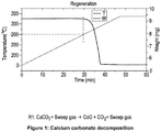
- the raw material used in the experiment was calcium carbonate (CaCO 3 ) which was decomposed to CaO and CO 2 by maintaining appropriate CO 2 partial pressure in the reactor. It can be seen from the Temperature/Time graph in Figure 1 that under certain CO 2 partial pressure, CaCO 3 started decomposing at 600°C (indicated by the dotted line). The kinetics are found to be reasonably fast at temperatures between 650-700°C.
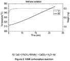
- the reduced calcium carbonate which is converted to CaO then was carbonized back in the presence of VAM at a temperature of 550°C which is well below the auto ignition temperature of methane. This may be due to catalytic effect of CaO on methane combustion and simultaneous capture of CO 2 as CaCO 3 .
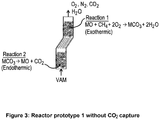
- the reactor prototype 1 as shown in Figure 3 is a lamella type reactor in which the combustion + carbonation reactions occur in upper zone as described by reaction 1.
- the mineral/metal carbonates formed will fall down into a bottom zone due to increased density where decomposition reaction 2 occurs.
- This reactor prototype does not provide an option of CO 2 capture in gaseous form. This only provides an option of CO 2 capture by mineral carbonation by passing several types of minerals as described above in once through mode.
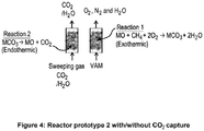
- the reactor prototype 2 as shown in Figure 4 is a fixed bed reactor in which the combustion + carbonation reactions occur in one bed and the regeneration by decomposition in another. The gases will be switched between two reactor beds as soon as the reactions are accomplished.
- This design can be used both with or without CO 2 capture, both as gaseous CO 2 capture or mineral carbonation (i.e. if one bed is used).
- the reactor prototype 3 as shown in Figure 5 is a novel double pipe reactor in which the combustion + carbonation reactions and decomposition are conducted in separate reactors. Instead of gas switching, mineral/metal oxide particles are circulated between the two reactors. This design can be effectively used for gaseous CO 2 capture.
- the reactor prototype 4 as shown in Figure 6 is illustrating the use of heat storage/transfer media made of ceramic and silica gel in the MCLR/SDLR processes.
- the reactor prototype 5 as shown in Figure 7 is another example of the use of heat storage/transfer media made of ceramic and silica gel in the MCLR/SDLR processes.
- Figure 8 shows the integration of MCLR or SDLR where additional heat available from the processes is used for heating, electricity or cooling applications.
- FIG 9 shows how available heat from solar sources and steam input can be utilized with the process to create additional steam or supercritical fluid that may be used for heating, cooling or electricity generation while capturing CO2.
- the carbonation reactor CAR (1) utilizes combustion and carbonation in reaction 1 (see paragraphs 33 and 34) to exchange heat with the Calcination Reactor CAL (2) utilizing the regeneration reaction, while additional heat is provided from solar sources (6) to boost the temperatures in the transfer from CAR to CAL and in the CAL reactor.
- Additional heat exchangers HE1 and HE2 (3,4 & 5) are also employed in this process.
- FIGS 10 , 11 and 12 show how drainage gas, natural gas, or coal can similarly be used to provide the additional heat source both with and without CO2 capture.
Landscapes
- Engineering & Computer Science (AREA)
- Chemical & Material Sciences (AREA)
- Environmental & Geological Engineering (AREA)
- Chemical Kinetics & Catalysis (AREA)
- Biomedical Technology (AREA)
- Analytical Chemistry (AREA)
- General Chemical & Material Sciences (AREA)
- Oil, Petroleum & Natural Gas (AREA)
- Health & Medical Sciences (AREA)
- Mining & Mineral Resources (AREA)
- Life Sciences & Earth Sciences (AREA)
- General Life Sciences & Earth Sciences (AREA)
- Geochemistry & Mineralogy (AREA)
- Geology (AREA)
- Treating Waste Gases (AREA)
- Gas Separation By Absorption (AREA)
- Physical Or Chemical Processes And Apparatus (AREA)
Description
- This invention relates to the removal of ventilation air methane using a mineral looping reactor (MLR) or stone dust looping reactor (SDLR) and has been devised not only to remove methane from ventilation air in coal mines at lower operating costs but also to capture CO2 and thus reduce emissions.
- Globally, ventilation methane exceeds the equivalent of 237 million tonnes of carbon dioxide annually. Of this amount, around 10% has been emitted in Australia. Many countries including Australia are therefore developing emission abatement policies or step change technologies to reduce the emissions stemming from methane released during coal mining as low concentration Ventilation Air Methane (VAM). There are a number of technologies available which can reduce the VAM emissions including the applicants' own process for chemical looping removal of VAM which is the subject of International Patent Application
PCT/AU2012/001173 WO 2013/044308 , the contents of which are hereby incorporated. - VAM can be used as combustion air for conventional power stations, gas turbine/engines, and in kiln processes. Additionally, the lean-burning turbines specifically designed to handle low methane concentration VAM use compression to lower the concentration of methane required for ignition, and catalytic turbines, which employ a catalyst to lower the required temperature of ignition. Both of these processes require some enrichment of the gas stream to operate on VAM which can be achieved by mixing some of the pre-mining drainage gas or gasified coal slurry. The lean-burning turbines and catalytic turbines have potential to generate power.
- However, some of the mine sites where VAM is generated have very low power rates where additional power generation option may not be found very attractive. Also such technology has limited application due to handling large volumes of air with low and fluctuating concentration of methane. Moreover, distance between the possible power plant and mine site VAM source is a critical factor in evaluating economic feasibility of VAM utilization for heat and power generation. Therefore, VAM destruction methods are also being developed. Thermal flow reversal reactors (TFRR), Catalytic flow reversal reactors (CFRR), and Catalytic monolith reactors (CMR) are the technologies developed to mainly destruct VAM but have less potential to generate energy as a side benefit. They all employ heat exchange to bring the VAM to the auto-ignition temperature of methane and use the heat of reaction to compensate for thermal losses through the outlet air.
- Open flares are also one of the expensive options to destruct VAM as they need minimum 5% methane to operate. Oxidative coupling to produce the ethylene or other liquid hydrocarbon and catalytic combustion, though attractive options, utilise expensive catalysts made of Au, Ag, Pt, Pd which may deactivate in high dust environment. Furthermore, CH4 conversion rate is slow with such catalysts at low temperature. Activated carbon or carbon composites can also arrest methane in their pores to a certain extent at low temperature which then can be regenerated by releasing methane. However, extent of adsorption is very low and the amount of inventory needed is high which makes their commercial use impractical.
- According to a first aspect of the present invention, there is provided a method of removing methane from ventilation air including the steps of:
- i) reacting a ventilation air methane stream with a carbon dioxide scavenger to form a mineral carbonate; and
- ii) decomposing the mineral carbonate back to a mineral or mineral oxide.
- Preferably step i) is performed in a carbonation reactor and step ii) is performed in a separate calcination reactor, with carbon dioxide being captured from the calcination reactor.
- Preferably step i) and step ii) occur at the same temperature, without carbon dioxide capture.
- In one form of the invention step i) and step ii) occur in the same reactor.
- In one form of the invention the decomposed mineral carbonate is reused as the carbon dioxide scavenger in step i).
- In another form of the invention metal or metal oxides having a carbonation tendency are used as the carbon dioxide scavenger.
- In another form of the invention the carbon dioxide scavenger is a mineral or mineral waste having a carbonation tendency.
- In some instances any of the metal, metal oxides, mineral or mineral waste having a carbonation tendency is used once only in the reaction process.
- In a still further form of the invention the carbon dioxide scavenger is formed by stone dust rich in calcium carbonate.
- Preferably the stone dust is sourced from or adjacent to a mine site where the ventilation air methane is generated.
- Preferably additional heat generated during the reaction process, is used for electricity generation or heating or cooling purposes.
- Notwithstanding any other forms that may fall within its scope, one preferred form of the invention will now be described by way of example only with reference to the accompanying drawings in which:
-
Figure 1 is a graph showing calcium carbonate decomposition over time. -
Figure 2 is a graph showing ventilation air methane (VAM) carbonation reaction over time. -
Figure 3 shows a first prototype reactor without CO2 capture; -
Figure 4 shows a second prototype reactor both with and without CO2 capture; -
Figure 5 shows a third prototype reactor for CO2 capture; -
Figure 6 shows a fourth prototype reactor for CO2 capture; -
Figure 7 shows the first and second reaction steps in the fourth prototype reactor for CO2 capture; -
Figure 8 is a block diagram showing integration of MCLR/SDLR to utilise VAM for heating, cooling or electricity generation applications; -
Figure 9 shows the integration of the MCLR/SDLR process with steam and solar inputs with CO2 capture; -
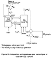
Figure 10 shows the integration of the MCLR/SDLR process with drainage gas, natural gas or coal as fuel with CO2 capture; -
Figure 11 shows the integration of the MCLR/SDLR process with drainage gas, natural gas or coal without CO2 capture; and -
Figure 12 shows the integration of the MCLR/SDLR process with drainage gas, natural gas or coal without CO2 capture. - The present invention using technologies referred to as "Mineral carbonate looping reactor (MCLR)" or "Stone dust looping reactor (SDLR)" is a new VAM destruction technology which can operate at lower costs compared to conventional technologies due to its low operating temperature. Moreover, it has an advantage of further reduction of emissions by capturing CO2 as by-product which is otherwise not captured in the current VAM utilization or destruction technologies due to the very dilute concentration in the VAM exit flue gas stream. The MCLR /SDLR processes suggested here can be explained by
reactions 
MCO3 → MO+ CO2 (2)
- The
reaction 1 is called combustion + carbonation where mineral/mineral oxide (MO) reacts with VAM stream to form mineral carbonate. This reaction is exothermic and releases energy. This reaction was found to occur at temperatures lower than methane auto ignition temperature. This may be due to catalytic effect of mineral/mineral oxide for low temperature combustion of methane as well as simultaneous capture of CO2 as mineral carbonate. In the regeneration reaction as explained byreaction 2, the carbonates are decomposed back to mineral/mineral oxide which then can be used again for methanation reaction. This reaction is endothermic and requires energy. The CO2 released duringreaction 2 can be captured and stored or used as a by-product. - From the energy balance point of view, the heat released from
reaction 1 can be utilized for the heat required byreaction 2. However,reaction 1 generates additional heat than the requirement byreaction 2 which further can be utilized/recovered to generate heating, electricity or cooling purposes. These configurations can be seen in the embodiments shown inFigures 9 and10 of the accompanying drawings. - Generally, both MCLR/SDLR processes are self-sufficient and do not need additional heat when the methane concentration in VAM is above 0.2 vol%.
- While the present invention covers two processes referred to as "Mineral carbonate looping reactor" (MCLR) or "Stone dust looping reactor" (SDLR), both processes undergo the same reactions referred to above. However, they use different CO2 scavengers depending on resources readily available at the particular site of application.
- All metals/metal oxides having a carbonation reaction (i.e. carbonate formation) tendency can be used as CO2 scavengers in the MCLR processes. Examples are PbO, CaO, MgO, Na, K, ZnO, MnO, PbO, Li2O, Sr, Fe and CuO.
- Any mineral which has carbonation reaction tendency can also be used in the MCLR process. Some examples are shown below:
Mg Olivine Mg2SiO4 Mg Serpentine Mg3Si2O5(OH)4 Wollastonite CaSiO3 Basalt Varies Magnetite Fe3O4 Brucite Mg(OH)2 Forsterite Mg2SiO4 Harzburgite CaMgSi2O6 Basalt Formula vary Orthopyroxene CaMgSi2O6 Dunite Mg2SiO3 with impurities - The mineral wastes such as steel making slags, blast furnace slag, construction demolition waste, coal and biomass bottom ash, fly ash with unburnt carbon, oil shale ash, paper mill wastes, incineration ash and municipal solid waste ash can also be used. The unburnt carbon in fly ash physically adsorbs methane and the minerals in fly ash catalyse the methane combustion at low temperatures with simultaneous CO2 capture.
- All the above mentioned minerals/mineral waste can be used as solids or in the form of aqueous solution in once through or in recycling mode.
- Stone dust rich in calcium carbonate, used at mine sites as a primary inert agent in the prevention of coal dust explosions can be used as a CO2 carrier in the MCLR process wherein the reactor/process is named Stone Duct Looping Reactor (SDLR). It is most effective by using fresh/used stone dust from mine sites for VAM mitigation. After several cycles in the SDLR process, the stone dust will lose its reactivity due to extensive sintering/agglomeration. The sintered/agglomerated used stone dust lumps from SDLR reactor can then be processed further in a ball mill for regrinding before their reuse in the process, or utilized by the mine to avoid coal dust explosions. In this manner, the SDLR process has a zero to low raw material cost for the CO2 carrier as it is a resource readily available and reusable at mine sites.
- Both above processes (MCLR and SDLR) are expected to operate between 300-700°C which is well below the auto-ignition temperature of dilute CH4. With proper thermal integration with 80% heat recovery, the processes are expected to require <0.1 m3 CH4 as an additional source of energy per 1000 m3 of VAM theoretically. Moreover, both processes will provide an option to capture and store or utilize CO2 as a by-product which will further reduce the emissions to a greater extent.
- The results of the preliminary experiments using a thermogravimetric analyser (TGA) are set out below. The raw material used in the experiment was calcium carbonate (CaCO3) which was decomposed to CaO and CO2 by maintaining appropriate CO2 partial pressure in the reactor. It can be seen from the Temperature/Time graph in
Figure 1 that under certain CO2 partial pressure, CaCO3 started decomposing at 600°C (indicated by the dotted line). The kinetics are found to be reasonably fast at temperatures between 650-700°C. - As shown in
Figure 2 , the reduced calcium carbonate which is converted to CaO then was carbonized back in the presence of VAM at a temperature of 550°C which is well below the auto ignition temperature of methane. This may be due to catalytic effect of CaO on methane combustion and simultaneous capture of CO2 as CaCO3. - Five examples of general reactor prototypes/layouts are given below.
- The
reactor prototype 1 as shown inFigure 3 is a lamella type reactor in which the combustion + carbonation reactions occur in upper zone as described byreaction 1. The mineral/metal carbonates formed will fall down into a bottom zone due to increased density wheredecomposition reaction 2 occurs. This reactor prototype does not provide an option of CO2 capture in gaseous form. This only provides an option of CO2 capture by mineral carbonation by passing several types of minerals as described above in once through mode. - The
reactor prototype 2 as shown inFigure 4 is a fixed bed reactor in which the combustion + carbonation reactions occur in one bed and the regeneration by decomposition in another. The gases will be switched between two reactor beds as soon as the reactions are accomplished. This design can be used both with or without CO2 capture, both as gaseous CO2 capture or mineral carbonation (i.e. if one bed is used). - The
reactor prototype 3 as shown inFigure 5 is a novel double pipe reactor in which the combustion + carbonation reactions and decomposition are conducted in separate reactors. Instead of gas switching, mineral/metal oxide particles are circulated between the two reactors. This design can be effectively used for gaseous CO2 capture. - The
reactor prototype 4 as shown inFigure 6 is illustrating the use of heat storage/transfer media made of ceramic and silica gel in the MCLR/SDLR processes. - The
reactor prototype 5 as shown inFigure 7 is another example of the use of heat storage/transfer media made of ceramic and silica gel in the MCLR/SDLR processes. -
Figure 8 shows the integration of MCLR or SDLR where additional heat available from the processes is used for heating, electricity or cooling applications. -
Figure 9 shows how available heat from solar sources and steam input can be utilized with the process to create additional steam or supercritical fluid that may be used for heating, cooling or electricity generation while capturing CO2. The carbonation reactor CAR (1) utilizes combustion and carbonation in reaction 1 (see paragraphs 33 and 34) to exchange heat with the Calcination Reactor CAL (2) utilizing the regeneration reaction, while additional heat is provided from solar sources (6) to boost the temperatures in the transfer from CAR to CAL and in the CAL reactor. Additional heat exchangers HE1 and HE2 (3,4 & 5) are also employed in this process. -
Figures 10 ,11 and12 show how drainage gas, natural gas, or coal can similarly be used to provide the additional heat source both with and without CO2 capture. - The MCLR process has many advantages over other VAM mitigation processes including:
- i) Low temperature operation which reduces fire and explosion risk associated with high temperature processes such as TFRR, CFRR and CMM.
- ii) It works at lower VAM concentrations (i.e. < 0.05 CH4 in VAM).
- iii) Low cost raw material (i.e. stone dust-rich in calcium) is readily available at mine sites. (In the case of CFRR, CMM and Chemical looping VAM, catalysts or oxygen carriers are needed and there will be issues of their fabrication, handling and stability for long term cyclic operation while minerals as CO2 scavengers are very low-cost and stable).
- iv) Reuse of the raw material with minimal treatment which eliminates the waste generation and disposal costs.
- v) Highly tolerant to moisture and dust environment compare to catalysts and ceramic pellets.
- vi) Lower energy footprints due to low temperature operation.
- vii) No issues in terms of acceptability and handling at coal mine sites.
- viii) Nearly zero emission process which provides an option to capture, store or use CO2.
Claims (11)
- A method of removing methane from ventilation air including the steps of:i) reacting a ventilation air methane stream with a carbon dioxide scavenger to form a mineral carbonate; andii) decomposing the mineral carbonate back to a mineral or mineral oxide.
- A method of removing methane from ventilation air as claimed in claim 1, wherein step i) is performed in a carbonation reactor and step ii) is performed in a separate calcination reactor, with carbon dioxide being captured from the calcination reactor.
- A method of removing methane from ventilation air as claimed in claim 1, wherein step i) and step ii) occur at the same temperature, without carbon dioxide capture.
- A method of removing methane from ventilation air as claimed in claim 3, wherein step i) and step ii) occur in the same reactor.
- A method of removing methane from ventilation air as claimed in any one of the preceding claims, wherein the decomposed mineral carbonate is reused as the carbon dioxide scavenger in step i).
- A method of removing methane from ventilation air as claimed in any one of the preceding claims, wherein metal or metal oxides having a carbonation tendency are used as the carbon dioxide scavenger.
- A method of removing methane from ventilation air as claimed in any one of the preceding claims, wherein the carbon dioxide scavenger is a mineral or mineral waste having a carbonation tendency.
- A method of removing methane from ventilation air as claimed in either claim 6 or claim 7, wherein any of the metal, metal oxides, mineral or mineral waste having a carbonation tendency is used once only in the reaction process.
- A method of removing methane from ventilation air as claimed in any one of claims 1 to 4, wherein the carbon dioxide scavenger is formed by stone dust rich in calcium carbonate.
- A method of removing methane from ventilation air as claimed in claim 9, wherein the stone dust is sourced from or adjacent to a mine site where the ventilation air methane is generated.
- A method as claimed in any one of the preceding claims, wherein additional heat generated during the reaction process, is used for electricity generation or heating or cooling purposes.
Applications Claiming Priority (2)
| Application Number | Priority Date | Filing Date | Title |
|---|---|---|---|
| AU2013902564A AU2013902564A0 (en) | 2013-07-11 | Mineral carbonate looping reactor for ventilation air methane mitigation | |
| PCT/AU2014/000713 WO2015003219A1 (en) | 2013-07-11 | 2014-07-10 | Mineral carbonate looping reactor for ventilation air methane mitigation |
Publications (3)
| Publication Number | Publication Date |
|---|---|
| EP3019268A1 EP3019268A1 (en) | 2016-05-18 |
| EP3019268A4 EP3019268A4 (en) | 2017-03-22 |
| EP3019268B1 true EP3019268B1 (en) | 2020-05-27 |
Family
ID=52279229
Family Applications (1)
| Application Number | Title | Priority Date | Filing Date |
|---|---|---|---|
| EP14822890.1A Active EP3019268B1 (en) | 2013-07-11 | 2014-07-10 | Method for ventilation air methane mitigation |
Country Status (5)
| Country | Link |
|---|---|
| US (1) | US20160158697A1 (en) |
| EP (1) | EP3019268B1 (en) |
| CN (1) | CN105764598B (en) |
| AU (1) | AU2014289972B2 (en) |
| WO (1) | WO2015003219A1 (en) |
Families Citing this family (4)
| Publication number | Priority date | Publication date | Assignee | Title |
|---|---|---|---|---|
| CN106595363B (en) * | 2016-12-09 | 2018-10-23 | 南京工业大学 | High-temperature calcium circulation thermochemical energy storage method and system |
| WO2022006112A1 (en) | 2020-06-29 | 2022-01-06 | Ohio State Innovation Foundation | Systems and methods for high reactant conversion through multiple reactant flow ratio staging |
| CN113739172A (en) * | 2021-08-12 | 2021-12-03 | 中国矿业大学 | Device and method for extracting gas by low-carbon synergistic utilization of high and low concentrations |
| WO2024086916A1 (en) * | 2022-10-24 | 2024-05-02 | Niall Davidson | Carbon capture in an air-cooled data center or crypto-mine |
Family Cites Families (13)
| Publication number | Priority date | Publication date | Assignee | Title |
|---|---|---|---|---|
| US4305734A (en) * | 1979-09-19 | 1981-12-15 | Mcgill Incorporated | Recovery of hydrocarbon components from a hydrocarbon-carrier gas mixture |
| US6254807B1 (en) * | 1998-01-12 | 2001-07-03 | Regents Of The University Of Minnesota | Control of H2 and CO produced in partial oxidation process |
| ES2575536T3 (en) * | 2003-10-07 | 2016-06-29 | Kao Corporation | Surfactant composition |
| CN101139239B (en) * | 2007-09-06 | 2010-04-14 | 西南化工研究设计院 | Sulfur-tolerant catalytic deoxidation process for methane-rich gas |
| US8740310B2 (en) * | 2008-06-20 | 2014-06-03 | Solvay Chemicals, Inc. | Mining method for co-extraction of non-combustible ore and mine methane |
| DE102008050816B4 (en) * | 2008-10-08 | 2013-09-05 | Alstom Technology Ltd. | Method and arrangement for separating CO2 from combustion exhaust gas |
| EP2385873B1 (en) * | 2008-11-19 | 2018-05-16 | The Ohio State University Research Foundation | Carbonation calcination reaction process for co2 capture using a highly regenerable sorbent |
| RU2550889C2 (en) * | 2010-01-26 | 2015-05-20 | Осака Гэс Ко., Лтд. | Combustible gas enrichment device |
| CN101912783B (en) * | 2010-08-31 | 2012-09-19 | 西南化工研究设计院 | Catalyst for combustion of ventilation air methane and preparation method thereof |
| US9677398B2 (en) * | 2011-04-15 | 2017-06-13 | Solvay Chemicals, Inc. | Use of ventilation air methane exhausted during mining of non-combustible ore in a surface appliance |
| IN2014KN00899A (en) | 2011-09-30 | 2015-10-09 | Newcastle Innovation Ltd | |
| CN202237711U (en) * | 2011-10-11 | 2012-05-30 | 北京科技大学 | Coal mine ventilation air methane enrichment device with adsorption tower exhaust end pumping step |
| US10537870B2 (en) * | 2012-02-01 | 2020-01-21 | Torrey Hills Technologies, Llc | Methane conversion device |
-
2014
- 2014-07-10 AU AU2014289972A patent/AU2014289972B2/en active Active
- 2014-07-10 WO PCT/AU2014/000713 patent/WO2015003219A1/en not_active Ceased
- 2014-07-10 US US14/903,867 patent/US20160158697A1/en not_active Abandoned
- 2014-07-10 EP EP14822890.1A patent/EP3019268B1/en active Active
- 2014-07-10 CN CN201480048471.8A patent/CN105764598B/en active Active
Non-Patent Citations (1)
| Title |
|---|
| None * |
Also Published As
| Publication number | Publication date |
|---|---|
| CN105764598B (en) | 2018-02-27 |
| AU2014289972B2 (en) | 2019-02-14 |
| EP3019268A4 (en) | 2017-03-22 |
| WO2015003219A1 (en) | 2015-01-15 |
| US20160158697A1 (en) | 2016-06-09 |
| CN105764598A (en) | 2016-07-13 |
| EP3019268A1 (en) | 2016-05-18 |
| AU2014289972A1 (en) | 2016-03-03 |
Similar Documents
| Publication | Publication Date | Title |
|---|---|---|
| Martínez et al. | Kinetics of calcination of partially carbonated particles in a Ca-looping system for CO2 capture | |
| CA2773080C (en) | Method of capturing co2 by means of cao and the exothermic reduction of a solid | |
| Manovic et al. | Competition of sulphation and carbonation reactions during looping cycles for CO2 capture by CaO-based sorbents | |
| US20110198861A1 (en) | Method for producing energy and capturing co2 | |
| EP2722094B1 (en) | Capturing of co2 from a process gas | |
| JP6626505B2 (en) | Method for producing hydrogen | |
| EP3986596B1 (en) | Method and a direct reduction plant for producing direct reduced iron | |
| CN104061568B (en) | A kind of Cu/Ca based compounds combined cycle catches CO2Method and device | |
| KR101659441B1 (en) | Device and Process for multi-stage of catalytic reaction occurring in at least two reaction modules including catalytic reactor and adsorption reactor | |
| AU2014289972B2 (en) | Mineral carbonate looping reactor for ventilation air methane mitigation | |
| EP4163266A1 (en) | Method for separating and recovering co2 in cement production exhaust gas, and co2 separation and recovery device | |
| AU2012315483B2 (en) | Chemical looping removal of ventilation air methane | |
| Shah et al. | A feasibility study on a novel stone dust looping process for abatement of ventilation air methane | |
| JP2022000405A (en) | Cement production method and cement production system | |
| JP2013081873A (en) | Co2 recovery method for reactivatable solid absorbent | |
| WO2021246318A1 (en) | Method for producing methane from co2 in cement production exhaust gas, and methanation apparatus | |
| CN212594913U (en) | Denitration, remove dioxin, dust removal function desulfurization dust pelletizing system as an organic whole | |
| JP2018058002A (en) | Gas treatment apparatus and gas treatment method | |
| KR20170087812A (en) | Device and Process for multi-stage of catalytic reaction occurring in at least two reaction modules including catalytic reactor and adsorption reactor | |
| JP7230884B2 (en) | CO2 Utilization Method and CO2 Utilization System in Exhaust Gas from Cement Manufacturing | |
| CN203373290U (en) | Sulfur-containing product manufacturing equipment | |
| JP2009242714A (en) | Waste gasification disposal system | |
| JP2022099610A (en) | Method for producing calcium oxide | |
| JP2021191731A (en) | Method for utilizing co2 in cement production exhaust gas, and co2 utilization system | |
| JP2021187721A (en) | Utilization method of co2 in cement manufacture exhaust gas and co2 utilization system |
Legal Events
| Date | Code | Title | Description |
|---|---|---|---|
| PUAI | Public reference made under article 153(3) epc to a published international application that has entered the european phase |
Free format text: ORIGINAL CODE: 0009012 |
|
| 17P | Request for examination filed |
Effective date: 20160210 |
|
| AK | Designated contracting states |
Kind code of ref document: A1 Designated state(s): AL AT BE BG CH CY CZ DE DK EE ES FI FR GB GR HR HU IE IS IT LI LT LU LV MC MK MT NL NO PL PT RO RS SE SI SK SM TR |
|
| AX | Request for extension of the european patent |
Extension state: BA ME |
|
| DAX | Request for extension of the european patent (deleted) | ||
| A4 | Supplementary search report drawn up and despatched |
Effective date: 20170220 |
|
| RIC1 | Information provided on ipc code assigned before grant |
Ipc: B01J 8/00 20060101ALI20170214BHEP Ipc: B01D 53/72 20060101ALI20170214BHEP Ipc: B01D 53/34 20060101AFI20170214BHEP Ipc: E21F 7/00 20060101ALI20170214BHEP Ipc: B01D 53/46 20060101ALI20170214BHEP |
|
| RAP1 | Party data changed (applicant data changed or rights of an application transferred) |
Owner name: THE UNIVERSITY OF NEWCASTLE |
|
| STAA | Information on the status of an ep patent application or granted ep patent |
Free format text: STATUS: EXAMINATION IS IN PROGRESS |
|
| 17Q | First examination report despatched |
Effective date: 20190618 |
|
| REG | Reference to a national code |
Ref country code: DE Ref legal event code: R079 Ref document number: 602014066003 Country of ref document: DE Free format text: PREVIOUS MAIN CLASS: B01D0053340000 Ipc: B01D0053720000 |
|
| GRAP | Despatch of communication of intention to grant a patent |
Free format text: ORIGINAL CODE: EPIDOSNIGR1 |
|
| STAA | Information on the status of an ep patent application or granted ep patent |
Free format text: STATUS: GRANT OF PATENT IS INTENDED |
|
| RIC1 | Information provided on ipc code assigned before grant |
Ipc: B01J 8/00 20060101ALI20191127BHEP Ipc: B01D 53/81 20060101ALI20191127BHEP Ipc: E21F 7/00 20060101ALI20191127BHEP Ipc: B01D 53/72 20060101AFI20191127BHEP |
|
| INTG | Intention to grant announced |
Effective date: 20191220 |
|
| GRAS | Grant fee paid |
Free format text: ORIGINAL CODE: EPIDOSNIGR3 |
|
| GRAA | (expected) grant |
Free format text: ORIGINAL CODE: 0009210 |
|
| STAA | Information on the status of an ep patent application or granted ep patent |
Free format text: STATUS: THE PATENT HAS BEEN GRANTED |
|
| AK | Designated contracting states |
Kind code of ref document: B1 Designated state(s): AL AT BE BG CH CY CZ DE DK EE ES FI FR GB GR HR HU IE IS IT LI LT LU LV MC MK MT NL NO PL PT RO RS SE SI SK SM TR |
|
| REG | Reference to a national code |
Ref country code: GB Ref legal event code: FG4D |
|
| REG | Reference to a national code |
Ref country code: CH Ref legal event code: EP |
|
| REG | Reference to a national code |
Ref country code: DE Ref legal event code: R096 Ref document number: 602014066003 Country of ref document: DE |
|
| REG | Reference to a national code |
Ref country code: AT Ref legal event code: REF Ref document number: 1273950 Country of ref document: AT Kind code of ref document: T Effective date: 20200615 |
|
| REG | Reference to a national code |
Ref country code: LT Ref legal event code: MG4D |
|
| PG25 | Lapsed in a contracting state [announced via postgrant information from national office to epo] |
Ref country code: IS Free format text: LAPSE BECAUSE OF FAILURE TO SUBMIT A TRANSLATION OF THE DESCRIPTION OR TO PAY THE FEE WITHIN THE PRESCRIBED TIME-LIMIT Effective date: 20200927 Ref country code: GR Free format text: LAPSE BECAUSE OF FAILURE TO SUBMIT A TRANSLATION OF THE DESCRIPTION OR TO PAY THE FEE WITHIN THE PRESCRIBED TIME-LIMIT Effective date: 20200828 Ref country code: LT Free format text: LAPSE BECAUSE OF FAILURE TO SUBMIT A TRANSLATION OF THE DESCRIPTION OR TO PAY THE FEE WITHIN THE PRESCRIBED TIME-LIMIT Effective date: 20200527 Ref country code: NO Free format text: LAPSE BECAUSE OF FAILURE TO SUBMIT A TRANSLATION OF THE DESCRIPTION OR TO PAY THE FEE WITHIN THE PRESCRIBED TIME-LIMIT Effective date: 20200827 Ref country code: SE Free format text: LAPSE BECAUSE OF FAILURE TO SUBMIT A TRANSLATION OF THE DESCRIPTION OR TO PAY THE FEE WITHIN THE PRESCRIBED TIME-LIMIT Effective date: 20200527 Ref country code: FI Free format text: LAPSE BECAUSE OF FAILURE TO SUBMIT A TRANSLATION OF THE DESCRIPTION OR TO PAY THE FEE WITHIN THE PRESCRIBED TIME-LIMIT Effective date: 20200527 Ref country code: PT Free format text: LAPSE BECAUSE OF FAILURE TO SUBMIT A TRANSLATION OF THE DESCRIPTION OR TO PAY THE FEE WITHIN THE PRESCRIBED TIME-LIMIT Effective date: 20200928 |
|
| REG | Reference to a national code |
Ref country code: NL Ref legal event code: MP Effective date: 20200527 |
|
| PG25 | Lapsed in a contracting state [announced via postgrant information from national office to epo] |
Ref country code: HR Free format text: LAPSE BECAUSE OF FAILURE TO SUBMIT A TRANSLATION OF THE DESCRIPTION OR TO PAY THE FEE WITHIN THE PRESCRIBED TIME-LIMIT Effective date: 20200527 Ref country code: LV Free format text: LAPSE BECAUSE OF FAILURE TO SUBMIT A TRANSLATION OF THE DESCRIPTION OR TO PAY THE FEE WITHIN THE PRESCRIBED TIME-LIMIT Effective date: 20200527 Ref country code: RS Free format text: LAPSE BECAUSE OF FAILURE TO SUBMIT A TRANSLATION OF THE DESCRIPTION OR TO PAY THE FEE WITHIN THE PRESCRIBED TIME-LIMIT Effective date: 20200527 Ref country code: BG Free format text: LAPSE BECAUSE OF FAILURE TO SUBMIT A TRANSLATION OF THE DESCRIPTION OR TO PAY THE FEE WITHIN THE PRESCRIBED TIME-LIMIT Effective date: 20200827 |
|
| REG | Reference to a national code |
Ref country code: AT Ref legal event code: MK05 Ref document number: 1273950 Country of ref document: AT Kind code of ref document: T Effective date: 20200527 |
|
| PG25 | Lapsed in a contracting state [announced via postgrant information from national office to epo] |
Ref country code: AL Free format text: LAPSE BECAUSE OF FAILURE TO SUBMIT A TRANSLATION OF THE DESCRIPTION OR TO PAY THE FEE WITHIN THE PRESCRIBED TIME-LIMIT Effective date: 20200527 Ref country code: NL Free format text: LAPSE BECAUSE OF FAILURE TO SUBMIT A TRANSLATION OF THE DESCRIPTION OR TO PAY THE FEE WITHIN THE PRESCRIBED TIME-LIMIT Effective date: 20200527 |
|
| PG25 | Lapsed in a contracting state [announced via postgrant information from national office to epo] |
Ref country code: EE Free format text: LAPSE BECAUSE OF FAILURE TO SUBMIT A TRANSLATION OF THE DESCRIPTION OR TO PAY THE FEE WITHIN THE PRESCRIBED TIME-LIMIT Effective date: 20200527 Ref country code: ES Free format text: LAPSE BECAUSE OF FAILURE TO SUBMIT A TRANSLATION OF THE DESCRIPTION OR TO PAY THE FEE WITHIN THE PRESCRIBED TIME-LIMIT Effective date: 20200527 Ref country code: CZ Free format text: LAPSE BECAUSE OF FAILURE TO SUBMIT A TRANSLATION OF THE DESCRIPTION OR TO PAY THE FEE WITHIN THE PRESCRIBED TIME-LIMIT Effective date: 20200527 Ref country code: RO Free format text: LAPSE BECAUSE OF FAILURE TO SUBMIT A TRANSLATION OF THE DESCRIPTION OR TO PAY THE FEE WITHIN THE PRESCRIBED TIME-LIMIT Effective date: 20200527 Ref country code: AT Free format text: LAPSE BECAUSE OF FAILURE TO SUBMIT A TRANSLATION OF THE DESCRIPTION OR TO PAY THE FEE WITHIN THE PRESCRIBED TIME-LIMIT Effective date: 20200527 Ref country code: DK Free format text: LAPSE BECAUSE OF FAILURE TO SUBMIT A TRANSLATION OF THE DESCRIPTION OR TO PAY THE FEE WITHIN THE PRESCRIBED TIME-LIMIT Effective date: 20200527 Ref country code: SM Free format text: LAPSE BECAUSE OF FAILURE TO SUBMIT A TRANSLATION OF THE DESCRIPTION OR TO PAY THE FEE WITHIN THE PRESCRIBED TIME-LIMIT Effective date: 20200527 Ref country code: IT Free format text: LAPSE BECAUSE OF FAILURE TO SUBMIT A TRANSLATION OF THE DESCRIPTION OR TO PAY THE FEE WITHIN THE PRESCRIBED TIME-LIMIT Effective date: 20200527 |
|
| PG25 | Lapsed in a contracting state [announced via postgrant information from national office to epo] |
Ref country code: PL Free format text: LAPSE BECAUSE OF FAILURE TO SUBMIT A TRANSLATION OF THE DESCRIPTION OR TO PAY THE FEE WITHIN THE PRESCRIBED TIME-LIMIT Effective date: 20200527 Ref country code: MC Free format text: LAPSE BECAUSE OF FAILURE TO SUBMIT A TRANSLATION OF THE DESCRIPTION OR TO PAY THE FEE WITHIN THE PRESCRIBED TIME-LIMIT Effective date: 20200527 Ref country code: SK Free format text: LAPSE BECAUSE OF FAILURE TO SUBMIT A TRANSLATION OF THE DESCRIPTION OR TO PAY THE FEE WITHIN THE PRESCRIBED TIME-LIMIT Effective date: 20200527 |
|
| REG | Reference to a national code |
Ref country code: CH Ref legal event code: PL |
|
| REG | Reference to a national code |
Ref country code: DE Ref legal event code: R097 Ref document number: 602014066003 Country of ref document: DE |
|
| PLBE | No opposition filed within time limit |
Free format text: ORIGINAL CODE: 0009261 |
|
| STAA | Information on the status of an ep patent application or granted ep patent |
Free format text: STATUS: NO OPPOSITION FILED WITHIN TIME LIMIT |
|
| GBPC | Gb: european patent ceased through non-payment of renewal fee |
Effective date: 20200827 |
|
| REG | Reference to a national code |
Ref country code: BE Ref legal event code: MM Effective date: 20200731 |
|
| PG25 | Lapsed in a contracting state [announced via postgrant information from national office to epo] |
Ref country code: LI Free format text: LAPSE BECAUSE OF NON-PAYMENT OF DUE FEES Effective date: 20200731 Ref country code: LU Free format text: LAPSE BECAUSE OF NON-PAYMENT OF DUE FEES Effective date: 20200710 Ref country code: FR Free format text: LAPSE BECAUSE OF NON-PAYMENT OF DUE FEES Effective date: 20200727 Ref country code: CH Free format text: LAPSE BECAUSE OF NON-PAYMENT OF DUE FEES Effective date: 20200731 |
|
| 26N | No opposition filed |
Effective date: 20210302 |
|
| PG25 | Lapsed in a contracting state [announced via postgrant information from national office to epo] |
Ref country code: SI Free format text: LAPSE BECAUSE OF FAILURE TO SUBMIT A TRANSLATION OF THE DESCRIPTION OR TO PAY THE FEE WITHIN THE PRESCRIBED TIME-LIMIT Effective date: 20200527 Ref country code: BE Free format text: LAPSE BECAUSE OF NON-PAYMENT OF DUE FEES Effective date: 20200731 |
|
| PG25 | Lapsed in a contracting state [announced via postgrant information from national office to epo] |
Ref country code: GB Free format text: LAPSE BECAUSE OF NON-PAYMENT OF DUE FEES Effective date: 20200827 Ref country code: IE Free format text: LAPSE BECAUSE OF NON-PAYMENT OF DUE FEES Effective date: 20200710 |
|
| PG25 | Lapsed in a contracting state [announced via postgrant information from national office to epo] |
Ref country code: TR Free format text: LAPSE BECAUSE OF FAILURE TO SUBMIT A TRANSLATION OF THE DESCRIPTION OR TO PAY THE FEE WITHIN THE PRESCRIBED TIME-LIMIT Effective date: 20200527 Ref country code: MT Free format text: LAPSE BECAUSE OF FAILURE TO SUBMIT A TRANSLATION OF THE DESCRIPTION OR TO PAY THE FEE WITHIN THE PRESCRIBED TIME-LIMIT Effective date: 20200527 Ref country code: CY Free format text: LAPSE BECAUSE OF FAILURE TO SUBMIT A TRANSLATION OF THE DESCRIPTION OR TO PAY THE FEE WITHIN THE PRESCRIBED TIME-LIMIT Effective date: 20200527 |
|
| PG25 | Lapsed in a contracting state [announced via postgrant information from national office to epo] |
Ref country code: MK Free format text: LAPSE BECAUSE OF FAILURE TO SUBMIT A TRANSLATION OF THE DESCRIPTION OR TO PAY THE FEE WITHIN THE PRESCRIBED TIME-LIMIT Effective date: 20200527 |
|
| P01 | Opt-out of the competence of the unified patent court (upc) registered |
Effective date: 20230522 |
|
| PGFP | Annual fee paid to national office [announced via postgrant information from national office to epo] |
Ref country code: DE Payment date: 20250722 Year of fee payment: 12 |