EP3018748A1 - Fuel cell device - Google Patents
Fuel cell device Download PDFInfo
- Publication number
- EP3018748A1 EP3018748A1 EP15193005.4A EP15193005A EP3018748A1 EP 3018748 A1 EP3018748 A1 EP 3018748A1 EP 15193005 A EP15193005 A EP 15193005A EP 3018748 A1 EP3018748 A1 EP 3018748A1
- Authority
- EP
- European Patent Office
- Prior art keywords
- stacking direction
- cell stack
- shaft
- case
- fuel cell
- Prior art date
- Legal status (The legal status is an assumption and is not a legal conclusion. Google has not performed a legal analysis and makes no representation as to the accuracy of the status listed.)
- Granted
Links
- 239000000446 fuel Substances 0.000 title claims abstract description 57
- XEEYBQQBJWHFJM-UHFFFAOYSA-N Iron Chemical compound [Fe] XEEYBQQBJWHFJM-UHFFFAOYSA-N 0.000 claims description 22
- 229910052782 aluminium Inorganic materials 0.000 claims description 12
- XAGFODPZIPBFFR-UHFFFAOYSA-N aluminium Chemical compound [Al] XAGFODPZIPBFFR-UHFFFAOYSA-N 0.000 claims description 12
- 229910052742 iron Inorganic materials 0.000 claims description 11
- 230000008859 change Effects 0.000 description 16
- 239000000463 material Substances 0.000 description 12
- 239000007789 gas Substances 0.000 description 8
- 238000010248 power generation Methods 0.000 description 8
- 230000009467 reduction Effects 0.000 description 8
- 238000003780 insertion Methods 0.000 description 6
- 230000037431 insertion Effects 0.000 description 6
- RTAQQCXQSZGOHL-UHFFFAOYSA-N Titanium Chemical compound [Ti] RTAQQCXQSZGOHL-UHFFFAOYSA-N 0.000 description 5
- 239000002826 coolant Substances 0.000 description 5
- 239000010936 titanium Substances 0.000 description 5
- 229910052719 titanium Inorganic materials 0.000 description 5
- 230000000694 effects Effects 0.000 description 3
- 238000012986 modification Methods 0.000 description 3
- 230000004048 modification Effects 0.000 description 3
- 229910000831 Steel Inorganic materials 0.000 description 2
- 229910000963 austenitic stainless steel Inorganic materials 0.000 description 2
- 238000009792 diffusion process Methods 0.000 description 2
- 238000007599 discharging Methods 0.000 description 2
- 239000002737 fuel gas Substances 0.000 description 2
- 230000002452 interceptive effect Effects 0.000 description 2
- 239000007788 liquid Substances 0.000 description 2
- 229910000734 martensite Inorganic materials 0.000 description 2
- 238000012544 monitoring process Methods 0.000 description 2
- 229910001220 stainless steel Inorganic materials 0.000 description 2
- 239000010935 stainless steel Substances 0.000 description 2
- 239000010959 steel Substances 0.000 description 2
- 239000004020 conductor Substances 0.000 description 1
- 238000006073 displacement reaction Methods 0.000 description 1
- 239000012212 insulator Substances 0.000 description 1
- 239000012528 membrane Substances 0.000 description 1
- 229910052751 metal Inorganic materials 0.000 description 1
- 239000002184 metal Substances 0.000 description 1
- 239000007769 metal material Substances 0.000 description 1
- 238000000034 method Methods 0.000 description 1
- 239000007800 oxidant agent Substances 0.000 description 1
- 230000002093 peripheral effect Effects 0.000 description 1
- 239000005518 polymer electrolyte Substances 0.000 description 1
Images

Classifications
-
- H—ELECTRICITY
- H01—ELECTRIC ELEMENTS
- H01M—PROCESSES OR MEANS, e.g. BATTERIES, FOR THE DIRECT CONVERSION OF CHEMICAL ENERGY INTO ELECTRICAL ENERGY
- H01M8/00—Fuel cells; Manufacture thereof
- H01M8/24—Grouping of fuel cells, e.g. stacking of fuel cells
- H01M8/2465—Details of groupings of fuel cells
- H01M8/247—Arrangements for tightening a stack, for accommodation of a stack in a tank or for assembling different tanks
- H01M8/2475—Enclosures, casings or containers of fuel cell stacks
-
- H—ELECTRICITY
- H01—ELECTRIC ELEMENTS
- H01M—PROCESSES OR MEANS, e.g. BATTERIES, FOR THE DIRECT CONVERSION OF CHEMICAL ENERGY INTO ELECTRICAL ENERGY
- H01M8/00—Fuel cells; Manufacture thereof
- H01M8/24—Grouping of fuel cells, e.g. stacking of fuel cells
- H01M8/2465—Details of groupings of fuel cells
- H01M8/247—Arrangements for tightening a stack, for accommodation of a stack in a tank or for assembling different tanks
- H01M8/248—Means for compression of the fuel cell stacks
-
- H—ELECTRICITY
- H01—ELECTRIC ELEMENTS
- H01M—PROCESSES OR MEANS, e.g. BATTERIES, FOR THE DIRECT CONVERSION OF CHEMICAL ENERGY INTO ELECTRICAL ENERGY
- H01M8/00—Fuel cells; Manufacture thereof
- H01M8/24—Grouping of fuel cells, e.g. stacking of fuel cells
- H01M8/2465—Details of groupings of fuel cells
- H01M8/2484—Details of groupings of fuel cells characterised by external manifolds
-
- H—ELECTRICITY
- H01—ELECTRIC ELEMENTS
- H01M—PROCESSES OR MEANS, e.g. BATTERIES, FOR THE DIRECT CONVERSION OF CHEMICAL ENERGY INTO ELECTRICAL ENERGY
- H01M8/00—Fuel cells; Manufacture thereof
- H01M8/10—Fuel cells with solid electrolytes
- H01M2008/1095—Fuel cells with polymeric electrolytes
-
- Y—GENERAL TAGGING OF NEW TECHNOLOGICAL DEVELOPMENTS; GENERAL TAGGING OF CROSS-SECTIONAL TECHNOLOGIES SPANNING OVER SEVERAL SECTIONS OF THE IPC; TECHNICAL SUBJECTS COVERED BY FORMER USPC CROSS-REFERENCE ART COLLECTIONS [XRACs] AND DIGESTS
- Y02—TECHNOLOGIES OR APPLICATIONS FOR MITIGATION OR ADAPTATION AGAINST CLIMATE CHANGE
- Y02E—REDUCTION OF GREENHOUSE GAS [GHG] EMISSIONS, RELATED TO ENERGY GENERATION, TRANSMISSION OR DISTRIBUTION
- Y02E60/00—Enabling technologies; Technologies with a potential or indirect contribution to GHG emissions mitigation
- Y02E60/30—Hydrogen technology
- Y02E60/50—Fuel cells
Definitions
- the invention relates to a fuel cell device.
- JP 2013-012325 A describes a fuel cell device that includes a tension shaft disposed along a bottom surface of a cell stack in a state in which a fuel cell is accommodated in a case.
- One end of the tension shaft is fixed to a case side surface opposing an end surface of the cell stack in a stacking direction and the other end thereof is fixed to an end plate positioned on the opposite side of the cell stack from the above-mentioned case side surface, and the case, the cell stack, and the end plate are thereby fastened to each other.
- the case and the tension shaft are formed of a metal material of the same type such as steel.
- the tension shaft is a rod member, the cross-sectional area of the tension shaft along a direction perpendicular to the stacking direction is smaller than the cross-sectional area of the case along the direction perpendicular to the stacking direction. Consequently, the rigidity of the tension shaft is lower than the rigidity of the case in the direction perpendicular to the stacking direction.
- the temperature of the cell stack increases during power generation, and the cell stack thermally expands and a compressive load increases.
- the invention provides the fuel cell device capable of preventing the reduction in parallelism between the unit cells.
- An aspect of the invention relates to a fuel cell device including: a cell stack including a plurality of unit cells that are stacked; a case including a cover portion that covers one of side surfaces of the cell stack, the side surfaces of the cell stack extending along a stacking direction along which the plurality of unit cells are stacked; an end plate connected to one end portion of the cover portion in the stacking direction and disposed on an outer side of the cell stack in the stacking direction; and a fastening member that extends in parallel with the stacking direction on an opposite side of the cell stack from the cover portion, that includes one end portion in the stacking direction connected to the end plate and another end portion in the stacking direction connected to the case, and that fastens the cell stack, the end plate, and the case to each other in the stacking direction.
- a thermal expansion coefficient of the cover portion is larger than a thermal expansion coefficient of the fastening member. According to the fuel cell device having the above configuration, since the thermal expansion coefficient of the fastening member is lower than the thermal expansion coefficient of the cover portion, in the case where the rigidity of the fastening member is lower than the rigidity of the cover portion, it is possible to reduce a difference in dimensional change in the stacking direction between the side of the fastening member and the side of the cover portion in the cell stack resulting from the difference in rigidity. Accordingly, it is possible to prevent the reduction in parallelism between the unit cells.
- a cross-sectional area of the fastening member along a direction perpendicular to the stacking direction may be smaller than a cross-sectional area of the cover portion along the direction perpendicular to the stacking direction.
- the rigidity of the cover portion is higher than the rigidity of the fastening member.
- the case may be formed of aluminum, and the fastening member may be formed of iron.
- the thermal expansion coefficient of the case is about twice as large as the thermal expansion coefficient of the fastening member, and hence, even in the case where a difference in cross-sectional area between the fastening member and the cover portion is large, it is possible to reduce the difference in dimensional change. Consequently, it is possible to reduce the cross-sectional area of the fastening member, and prevent an increase in the size of the fuel cell device.
- the fastening member may include a plurality of rod members disposed so as to be spaced apart from each other. According to the fuel cell device having the above configuration, since the fastening member include the plurality of the rod members disposed so as to be spaced apart from each other, it is possible to bear a larger compressive load of the cell stack as compared with a configuration in which the fastening member is formed of a plate member having the same cross-sectional area as that of the plurality of the rod members. In addition, it is possible to distribute the load efficiently as compared with a configuration in which the fastening member is constituted by one rod member, and it is possible to fasten the cell stack stably, reduce the cross-sectional area per rod member, and prevent the increase in the size of the fuel cell device.
- FIG. 1 is a cross-sectional view showing a schematic configuration of a fuel cell device as the embodiment of the invention.
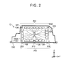
- FIG. 2 is a cross-sectional view showing a cross section of the fuel cell device in a direction perpendicular to a stacking direction.
- FIG. 2 shows a II-II cross section in FIG. 1 .
- a fuel cell device 10 includes what is called a polymer electrolyte fuel cell, and constitutes a fuel cell system with a supply section of reactive gases (a fuel gas and an oxidizer gas), and a supply section of a cooling medium.
- a fuel cell system is mounted on a fuel cell vehicle or the like as, e.g., a system for providing a drive power source, and is used.
- the fuel cell system may also be mounted on any other mobile unit instead of the fuel cell vehicle, and may also be used as a stationary fuel cell.
- the fuel cell device 10 includes a cell stack 102S, a first collector plate 160E, a second collector plate 160F, a pressure plate 170, a stack manifold 180, an end plate 190, a tension shaft 300, a case 500, and a lower cover 550.
- the cell stack 102S has a structure in which a plurality of unit cells 102 are stacked along a stacking direction SD.
- the unit cell 102 includes a membrane electrode assembly (MEA), a pair of gas diffusion layers that hold the MEA between them, and a pair of separators that hold a layered body of the MEA and the gas diffusion layers between them.
- the unit cell 102 has a plurality of flow path forming holes 105 that extend in a thickness direction. With this, the flow path (not shown) for supplying the reactive gas and the cooling medium to the unit cell 102 and the flow path (not shown) for discharging the reactive gas and the cooling medium from the unit cell 102 are formed along the stacking direction SD in the cell stack 102S.
- an X axis and a Y axis are determined such that an X-Y plane is parallel to the horizontal plane.
- the Y axis and a Z axis are directions perpendicular to each other.
- a +Z direction corresponds to a vertically upper direction and a -Z direction corresponds to a vertically lower direction.
- the fuel cell device 10 is placed such that the stacking direction SD is parallel to the X axis.
- the shape of the surface of the unit cell 102 perpendicular to the stacking direction SD is substantially rectangular, and the unit cell 102 is disposed such that its longitudinal direction is parallel to the Y axis.
- Concave portions 106 are formed at four corners of the substantially rectangular shape in a plan view and the center of the lower side.
- the concave portions 106 of each unit cell 102 are arranged in the stacking direction SD, and grooves along the stacking direction SD are thereby formed at boundaries between an upper surface and side surfaces of the cell stack 102S, boundaries between a bottom surface and the side surfaces thereof, and the center of the bottom surface.
- the grooves formed by the concave portions 106 at both corners of the upper side prevent protruding portions 501 and 502 of the case 500 from interfering with the unit cell 102, and the grooves formed by the concave portions 106 at both corners of the lower side and the groove formed by the concave portion 106 at the center of the lower side prevent the tension shaft 300 and a connector for connection with a voltage monitoring unit that is not shown from interfering with the unit cell 102.
- the first collector plate 160E is disposed so as to be in contact with an end surface of the cell stack 102S in a +X direction.
- the first collector plate 160E has a three-layer structure in which a titanium layer, an aluminum layer, and the titanium layer are stacked, and an outer edge of the first collector plate 160E is covered with rubber.
- the second collector plate 160F is disposed so as to be in contact with an end surface of the cell stack 102S in a -X direction.
- the second collector plate 160F has a plurality of flow path forming holes that extend in the thickness direction.
- the second collector plate 160F is formed of aluminum.
- Each of the first collector plate 160E and the second collector plate 160F collects electric power generated by each unit cell 102 and outputs the electric power to the outside from a terminal that is not shown.
- the second collector plate 160F may also be formed by the three-layer structure.
- the two collector plates 160E and 160F may also be formed of any conductive material other than aluminum and titanium. Note that each of the collector plates 160E and 160F has a substantially rectangular shape in a plan view similarly to the unit cell 102.
- the pressure plate 170 is disposed on an outer side of the first collector plate 160E in the stacking direction SD (the +X direction). Note that an insulator (not shown) is disposed between the pressure plate 170 and the first collector plate 160E.
- the pressure plate 170 is fixed using a plurality of load adjustment screws 250 inserted into a plurality of through holes 510 formed in the case 500, and presses the cell stack 102S in the -X direction. Note that a thread is formed in an inner peripheral surface of each through hole 510, and the through hole 510 functions as a female thread.
- the pressure plate 170 similarly to the unit cell 102, the pressure plate 170 has a substantially rectangular shape in a plan view.
- the stack manifold 180 is disposed so as to be in contact with a surface of the second collector 160F in the -X direction.
- a flow path for supplying the reactive gas and the cooling medium to the cell stack 102S and a flow path for discharging the reactive gas and the cooling medium from the cell stack 102S are formed.
- a circulation pipe and a gas-liquid separator are mounted to the stack manifold 180 as components of a fuel gas supply system.
- the end plate 190 is disposed on an outer side of the cell stack 102S in the stacking direction SD, and is in contact with a surface of the stack manifold 180 in the -X direction.
- the end plate 190 is formed of aluminum, and covers an opening formed in a side surface of the case 500 in the -X direction.
- the end plate 190 is connected to an end portion of the tension shaft 300 using a plurality of nuts 450 in the vicinity of an end portion in the -Z direction.
- An end portion of the tension shaft 300 on the opposite side from the end portion connected to the end plate 190 is connected to the case 500 using the nut 450. Consequently, the end plate 190 is connected to the case 500 via the tension shaft 300.
- the end plate 190 is fixed to the case 500 using a plurality of bolts 460 in a portion around the opening formed in the side surface of the case 500 in the -X direction.
- the tension shaft 300 is provided to extend in parallel with the stacking direction SD vertically below the cell stack 102S. In other words, the tension shaft 300 is disposed on the opposite side of the cell stack 102S from a side surface of the case 500 in the +Z direction (hereinafter also referred to as an upper surface portion 503). As shown in FIG. 2 , the tension shaft 300 includes a first shaft 310, a second shaft 320, and a third shaft 330. Each of the first shaft 310, the second shaft 320, and the third shaft 330 has a circular cross section along the direction perpendicular to the stacking direction SD, and has a rod shape with a longitudinal direction along the stacking direction SD as an outer shape thereof.
- the first shaft 310 is accommodated in the groove formed along the stacking direction SD at the center of the bottom surface of the cell stack 102S.
- Each of the second shaft 320 and the third shaft 330 is accommodated in the groove formed along the stacking direction SD at the boundary between the bottom surface and the side surface of the cell stack 102S.
- the first shaft 310, the second shaft 320, and the third shaft 330 are disposed so as to be spaced apart from each other in a direction along the Y axis by a predetermined distance.
- the end portion of the tension shaft 300 in the -X direction is connected to the end plate 190 and the end portion thereof in the +X direction is connected to the case 500, whereby the cell stack 102S, the end plate 190, and the case 500 are fastened to each other, and the stack structure of the cell stack 102S is maintained.
- the three shafts 310 to 330 constituting the tension shaft 300 are formed of iron.
- the diameter of the first shaft 310 is larger than the diameters of the second shaft 320 and the third shaft 330. Note that the diameter of the second shaft 320 is equal to the diameter of the third shaft 330.
- the case 500 has a box shape as an outer shape thereof, and accommodates auxiliary equipment such as the voltage monitoring unit and the gas-liquid separator that are not shown in addition to the fuel cell including the cell stack 102S.
- the upper surface portion 503 of the case 500 has a plate shape as an outer shape thereof, and covers an upper surface of the cell stack 102S.
- the first protruding portion 501 that is provided to extend along the stacking direction SD is formed at an end portion of the upper surface portion 503 in a -Y direction. The first protruding portion 501 protrudes toward the cell stack 102S, and is accommodated in the groove formed at the boundary between the upper surface and the side surface of the cell stack 102S.
- the first protruding portion 501 prevents a positional displacement of each unit cell 102 in the direction perpendicular to the stacking direction SD.
- the second protruding portion 502 is different from the first protruding portion 501 in that the second protruding portion 502 is formed at an end portion of the upper surface portion 503 in a +Y direction, and other configurations are the same as those of the first protruding portion 501, and hence the detailed description thereof will be omitted.
- the cross-sectional area of the upper surface portion 503 along the direction perpendicular to the stacking direction SD is larger than the cross-sectional area of the tension shaft 300 (i.e., the sum of the cross-sectional areas of the three shafts 310 to 330).
- openings are formed in the side surfaces of the case 500 in the -X direction and the -Z direction.
- the opening in the side surface in the -X direction is covered with the end plate 190.
- the opening in the side surface in the -Z direction is covered with the lower cover 550.
- the plurality of the through holes 510 described above, a pressing member insertion hole 520 for inserting a pressing member when the fuel cell device 10 is assembled, and three tension shaft insertion holes 530 for inserting the tension shaft 300 are formed in the side surface of the case 500 in the +X direction.
- each of the other side surfaces of the case 500 (side surfaces in the +Y direction and the -Y direction) has a plate shape as an outer shape thereof.
- the case 500 is formed of an aluminum die-cast.
- the lower cover 550 is disposed vertically below the cell stack 102S, and covers the opening in the side surface of the case 500 in the -Z direction.
- the lower cover 550 is a plate member having a substantially rectangular shape in a plan view, has a size equal to that of the side surface of the case 500 in the -Z direction, and is fixed to the case 500 using a plurality of bolts 470.
- the lower cover 550 is formed of iron in this embodiment, but may also be formed of any other metal such as steel instead of iron.
- the tension shaft 300 functions as a fastening member
- each of the first shaft 310, the second shaft 320, and the third shaft 330 functions as a rod member.
- the upper surface portion 503 of the case 500 functions as a cover portion.
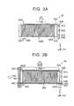
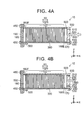
- FIGS. 3A and 3B and FIGS. 4A and 4B are sectional views schematically showing assembly steps of the fuel cell device 10.
- FIGS. 3A and 3B and FIGS. 4A and 4B show the chronological assembly steps of the fuel cell device 10 in this order.
- the cell stack 102S, the two collector plates 160E and 160F, the pressure plate 170, and the stack manifold 180 are inserted into the case 500 from the opening formed in the case 500, and are disposed.
- the cell stack 102S since the cell stack 102S is not compressed, part of the unit cells 102 on the side of an end portion in the -X direction in the cell stack 102S, the second collector plate 160F, and the stack manifold 180 are positioned on the outer side of the case 500 in the stacking direction SD.
- the end plate 190 is disposed so as to cover the opening formed in the side surface of the case 500 in the -X direction.
- the end plate 190 is pressed in a direction indicated by an open arrow in the drawing (the +X direction) by a pressurization unit that is not shown, and the cell stack 102S is compressed in the stacking direction SD.
- the tension shaft 300 is inserted from the tension shaft insertion hole 530.
- the end portion of the tension shaft 300 in the -X direction is fixed to the end plate 190 using the nut 450, and the end portion thereof in the +X direction is fixed to the case 500.
- the end plate 190 is fixed to the case 500 using the plurality of the bolts 460. With the fixation of the end plate 190 to the case 500, the cell stack 102S that is compressed in the stacking direction SD is accommodated in the case 500.
- a pressing member 600 is inserted from the pressing member insertion hole 520 formed in the side surface of the case 500 in the +X direction.
- the pressing member 600 is driven with power of the pressurization unit that is not shown, and presses the pressure plate 170 in a direction indicated by an open arrow in the drawing (the -X direction) with a predetermined load. With this pressing force, the pressure plate 170 presses the first collector plate 160E and the cell stack 102S. With this, the cell stack 102S is further compressed in the stacking direction SD.
- each load adjustment screw 250 is inserted into each through hole 510 in the side surface of the case 500 in the +X direction.
- the load adjustment screw 250 adjusts variations in the length of the cell stack 102S in the stacking direction SD. Accordingly, the load adjustment screw 250 is inserted until the load adjustment screw 250 comes into contact with the pressure plate 170. Since the pressure plate 170 is fixed using the load adjustment screw 250, the compressive load of the cell stack 102S is maintained at a predetermined level.
- the pressing member 600 is pulled out from the pressing member insertion hole 520, and a cover (not shown) is disposed at the pressing member insertion hole 520. Thereafter, the lower cover 550 is disposed at the opening in the side surface of the case 500 in the -Z direction, and the assembly of the fuel cell device 10 shown in FIG. 1 is completed.
- the cell stack 102S is accommodated in the case 500 in the state in which the predetermined compressive load is maintained with the fastening force of the tension shaft 300.
- the temperature of the cell stack 102S increases during power generation, and hence the cell stack 102S expands in the stacking direction SD due to thermal expansion of each unit cell 102. Accordingly, during power generation, the compressive load of the cell stack 102S accommodated in the case 500 increases.
- the cross-sectional area of the tension shaft 300 along the direction perpendicular to the stacking direction SD is smaller than the cross-sectional area of the upper surface portion 503 of the case 500.
- the rigidity of the tension shaft 300 based on the cross-sectional area is lower than the rigidity of the upper surface portion 503 based on the cross-sectional area. Consequently, with the increase of the compressive load of the cell stack 102S, the dimensional change of the tension shaft 300 in the stacking direction SD tends to be larger than the dimensional change of the upper surface portion 503 in the stacking direction SD. Therefore, the dimensional change on the side of the tension shaft 300 (the side of the bottom surface) in the cell stack 102S tends to be larger than the dimensional change on the side of the upper surface portion 503 (the side of the upper surface) in the cell stack 102S.
- the tension shaft 300 is formed of iron
- the upper surface portion 503 (the case 500) is formed of aluminum.
- the thermal expansion coefficient of iron is 11.7 ⁇ 10 -6 / °C
- the thermal expansion coefficient of aluminum is 23 ⁇ 10 -6 / °C. Consequently, when the temperature of the cell stack 102S increases during power generation and the compressive load of the cell stack 102S increases, the expansion of the tension shaft 300 is suppressed as compared with the expansion of the upper surface portion 503.
- the thermal expansion coefficient of the upper surface portion 503 (the case 500) is sufficiently larger than the thermal expansion coefficient of the tension shaft 300. Consequently, when the temperature of the cell stack 102S increases during power generation and the compressive load of the cell stack 102S increases, it is possible to suppress the dimensional change of the tension shaft 300 in the stacking direction SD sufficiently as compared with the dimensional change of the upper surface portion 503 in the stacking direction SD. Therefore, it is possible to reduce the cross-sectional area of the tension shaft 300, i.e., thinly form the tension shaft 300, and hence it is possible to prevent an increase in the size of the fuel cell device 10.
- the tension shaft 300 of this embodiment includes the three shafts 310 to 330. Accordingly, it is possible to distribute the load efficiently as compared with a configuration in which the tension shaft 300 is constituted by one shaft, and stably fasten the cell stack 102S, the end plate 190, and the case 500 to each other. In addition, it is possible to reduce the cross-sectional area per shaft, and prevent the increase in the size of the fuel cell device 10. Further, it is possible to bear a larger compressive load of the cell stack as compared with a configuration in which the fastening member is formed of a plate member having the same cross-sectional area as that of a plurality of shafts.
- the tension shaft 300 is formed of iron and the upper surface portion 503 (the case 500) is formed of aluminum, but the invention is not limited thereto.
- the thermal expansion coefficient of the material forming the upper surface portion 503 is larger than the thermal expansion coefficient of the material forming the tension shaft 300
- at least one of the upper surface portion 503 and the tension shaft 300 may also be formed of any material other than the materials in the above-described embodiment.
- the upper surface portion 503 may be formed of aluminum (thermal expansion coefficient: 23 ⁇ 10 -6 / °C), and the tension shaft 300 may be formed of martensite stainless steel (thermal expansion coefficient of SUS410: 9.9 ⁇ 10 -6 / °C) or titanium (thermal expansion coefficient: 8.4 ⁇ 10 -6 / °C).
- the upper surface portion 503 may be formed of austenitic stainless steel (thermal expansion coefficient of SUS304: 17.3 ⁇ 10 -6 / °C), and the tension shaft 300 may be formed of iron (thermal expansion coefficient: 11.7 ⁇ 10 -6 / °C) or martensite stainless steel (thermal expansion coefficient of SUS410: 9.9 ⁇ 10 -6 / °C).
- austenitic stainless steel thermal expansion coefficient of SUS304: 17.3 ⁇ 10 -6 / °C
- the tension shaft 300 may be formed of iron (thermal expansion coefficient: 11.7 ⁇ 10 -6 / °C) or martensite stainless steel (thermal expansion coefficient of SUS410: 9.9 ⁇ 10 -6 / °C).
- the upper surface portion 503 is preferably formed of the material having the thermal expansion coefficient sufficiently larger than that of the tension shaft 300.
- the thermal expansion coefficient of the material forming the upper surface portion 503 is preferably 1.2 or more times larger than the thermal expansion coefficient of the material forming the tension shaft 300, more preferably 1.5 or more times larger than the thermal expansion coefficient thereof, and even more preferably 1.8 or more times larger than the thermal expansion coefficient thereof.
- the case 500 is formed of the single material, but the upper surface portion 503 and the other portion of the case 500 may also be formed of different materials.
- the thermal expansion coefficient of the upper surface portion 503 larger than the thermal expansion coefficient of the tension shaft 300, effects similar to those of the fuel cell device 10 of the embodiment are achieved. That is, in general, the cover portion having the thermal expansion coefficient larger than the thermal expansion coefficient of the fastening member may be used in the fuel cell device 10 of the invention.
- the first shaft 310, the second shaft 320, and the third shaft 330 are formed of iron, but the invention is not limited thereto. At least one of the first shaft 310, the second shaft 320, and the third shaft 330 may also be formed of a different material.
- the thermal expansion coefficient of the tension shaft 300 means the average value of the individual thermal expansion coefficients of the three shafts 310 to 330. In this configuration as well, the thermal expansion coefficient of the tension shaft 300 is smaller than the thermal expansion coefficient of the upper surface portion 503. Note that the individual thermal expansion coefficients of the first shaft 310, the second shaft 320, and the third shaft 330 are preferably smaller than the thermal expansion coefficient of the upper surface portion 503.
- the tension shaft 300 may also include two or more first shafts 310 that are accommodated in the groove formed along the stacking direction SD in the bottom surface of the cell stack 102S.
- the tension shaft 300 may also include two or more second shafts 320 and two or more third shafts 330 that are accommodated in the grooves formed along the stacking direction SD at the boundaries between the bottom surface and the side surfaces of the cell stack 102S.
- one or two of the first shaft 310, the second shaft 320, and the third shaft 330 may also be omitted.
- first shaft 310, the second shaft 320, and the third shaft 330 are disposed so as to be spaced apart from each other in the direction along the Y axis by the predetermined distance, but the first shaft 310, the second shaft 320, and the third shaft 330 may not be disposed so as to be arranged in the direction along the Y axis, and may also be disposed so as to be in contact with each other.
- each of the cross-sectional shape of the first shaft 310, the cross-sectional shape of the second shaft 320, and the cross-sectional shape of the third shaft 330 is circular, but the cross-sectional shape thereof may also be any other cross-sectional shape such as an oblong shape or a polygonal shape instead of the circular shape.
- at least one of the first shaft 310, the second shaft 320, and the third shaft 330 may have a different cross-sectional shape.
- the diameter of the first shaft 310 is larger than the diameters of the second shaft 320 and the third shaft 330, but the diameter of the first shaft 310 may also be equal to or smaller than the diameters of the second shaft 320 and the third shaft 330. Moreover, the diameter of the second shaft 320 may be different from the diameter of the third shaft 330. Additionally, the tension shaft 300 may also be formed of one plate member.
- the configuration in which the tension shaft 300 is formed of a plurality of the rod members is preferable in the point that the configuration can bear a larger compressive load of the cell stack 102S as compared with the configuration in which the tension shaft 300 is formed of the plate member having the same cross-sectional area as that of the plurality of the rod members.
- the upper surface portion 503 includes the first protruding portion 501 and the second protruding portion 502 that are provided to extend along the stacking direction SD, but the invention is not limited thereto. At least one of the two protruding portions 501 and 502 may be omitted, and a plurality of the protruding portions 501 and 502 may be provided at the end portion in the -Y direction and at the end portion in the +Y direction.
- the cross-sectional area of the tension shaft 300 along the direction perpendicular to the stacking direction SD is smaller than the cross-sectional area of the upper surface portion 503, but the invention is not limited thereto.
- the cross-sectional area of the tension shaft 300 along the direction perpendicular to the stacking direction SD may be equal to or larger than the cross-sectional area of the upper surface portion 503.
- the case 500 may be formed of austenitic stainless steel (Young's modulus of SUS304: 197 GPa), and the tension shaft 300 may be formed of titanium (Young's modulus: 106GPa).
- the rigidity of the tension shaft 300 can be lower than the rigidity of the upper surface portion 503.
- the invention is not limited to the embodiment and the modifications described above, and the invention can be implemented in various configurations without departing from the scope thereof.
- the technical features in the embodiment and the modifications corresponding to the technical features of the invention can be appropriately replaced or combined in order to solve a part or all of the above problems or achieve a part or all of the above effects.
- any of the technical features, if not explained as essential in this specification, may be deleted as appropriate.
- the invention can be implemented in various forms.
- the invention can be implemented in forms such as a fuel cell system including the fuel cell device, and a vehicle on which the fuel cell system is mounted.
Landscapes
- Life Sciences & Earth Sciences (AREA)
- Engineering & Computer Science (AREA)
- Manufacturing & Machinery (AREA)
- Sustainable Development (AREA)
- Sustainable Energy (AREA)
- Chemical & Material Sciences (AREA)
- Chemical Kinetics & Catalysis (AREA)
- Electrochemistry (AREA)
- General Chemical & Material Sciences (AREA)
- Fuel Cell (AREA)
Abstract
Description
- The invention relates to a fuel cell device.
- Conventionally, a cell stack including a plurality of stacked unit cells is used in a fuel cell. The fuel cell including the cell stack is accommodated in a case in a state in which a load is applied to the cell stack in a stacking direction in order to maintain the stack structure of the cell stack. Japanese Patent Application Publication No.
2013-012325 JP 2013-012325 A - In the fuel cell device described in
JP 2013-012325 A JP 2013-012325 A - The invention provides the fuel cell device capable of preventing the reduction in parallelism between the unit cells.
- An aspect of the invention relates to a fuel cell device including: a cell stack including a plurality of unit cells that are stacked; a case including a cover portion that covers one of side surfaces of the cell stack, the side surfaces of the cell stack extending along a stacking direction along which the plurality of unit cells are stacked; an end plate connected to one end portion of the cover portion in the stacking direction and disposed on an outer side of the cell stack in the stacking direction; and a fastening member that extends in parallel with the stacking direction on an opposite side of the cell stack from the cover portion, that includes one end portion in the stacking direction connected to the end plate and another end portion in the stacking direction connected to the case, and that fastens the cell stack, the end plate, and the case to each other in the stacking direction. A thermal expansion coefficient of the cover portion is larger than a thermal expansion coefficient of the fastening member. According to the fuel cell device having the above configuration, since the thermal expansion coefficient of the fastening member is lower than the thermal expansion coefficient of the cover portion, in the case where the rigidity of the fastening member is lower than the rigidity of the cover portion, it is possible to reduce a difference in dimensional change in the stacking direction between the side of the fastening member and the side of the cover portion in the cell stack resulting from the difference in rigidity. Accordingly, it is possible to prevent the reduction in parallelism between the unit cells.
- A cross-sectional area of the fastening member along a direction perpendicular to the stacking direction may be smaller than a cross-sectional area of the cover portion along the direction perpendicular to the stacking direction. According to the fuel cell device having the above configuration, in the case where the Young's modulus of the fastening member is equal to the Young's modulus of the cover portion, the rigidity of the cover portion is higher than the rigidity of the fastening member. However, with the difference in thermal expansion coefficient between the fastening member and the cover portion, it is possible to prevent the reduction in parallelism between the unit cells.
- The case may be formed of aluminum, and the fastening member may be formed of iron. According to the fuel cell device having the above configuration, the thermal expansion coefficient of the case is about twice as large as the thermal expansion coefficient of the fastening member, and hence, even in the case where a difference in cross-sectional area between the fastening member and the cover portion is large, it is possible to reduce the difference in dimensional change. Consequently, it is possible to reduce the cross-sectional area of the fastening member, and prevent an increase in the size of the fuel cell device.
- The fastening member may include a plurality of rod members disposed so as to be spaced apart from each other. According to the fuel cell device having the above configuration, since the fastening member include the plurality of the rod members disposed so as to be spaced apart from each other, it is possible to bear a larger compressive load of the cell stack as compared with a configuration in which the fastening member is formed of a plate member having the same cross-sectional area as that of the plurality of the rod members. In addition, it is possible to distribute the load efficiently as compared with a configuration in which the fastening member is constituted by one rod member, and it is possible to fasten the cell stack stably, reduce the cross-sectional area per rod member, and prevent the increase in the size of the fuel cell device.
- Features, advantages, and technical and industrial significance of exemplary embodiments of the invention will be described below with reference to the accompanying drawings, in which like numerals denote like elements, and wherein:
-
FIG. 1 is a sectional view showing a schematic configuration of a fuel cell device as an embodiment of the invention; -
FIG. 2 is a cross-sectional view showing a cross section of the fuel cell device in a direction perpendicular to a stacking direction; -
FIGS. 3A and 3B are sectional views schematically showing assembly steps of afuel cell device 10; and -
FIGS. 4A and 4B are sectional views schematically showing assembly steps of thefuel cell device 10. - First, an embodiment of the invention will be described.
FIG. 1 is a cross-sectional view showing a schematic configuration of a fuel cell device as the embodiment of the invention.FIG. 2 is a cross-sectional view showing a cross section of the fuel cell device in a direction perpendicular to a stacking direction.FIG. 2 shows a II-II cross section inFIG. 1 . Afuel cell device 10 includes what is called a polymer electrolyte fuel cell, and constitutes a fuel cell system with a supply section of reactive gases (a fuel gas and an oxidizer gas), and a supply section of a cooling medium. Such a fuel cell system is mounted on a fuel cell vehicle or the like as, e.g., a system for providing a drive power source, and is used. Note that the fuel cell system may also be mounted on any other mobile unit instead of the fuel cell vehicle, and may also be used as a stationary fuel cell. - As shown in
FIG. 1 , thefuel cell device 10 includes acell stack 102S, afirst collector plate 160E, asecond collector plate 160F, apressure plate 170, astack manifold 180, anend plate 190, atension shaft 300, acase 500, and alower cover 550. - The
cell stack 102S has a structure in which a plurality ofunit cells 102 are stacked along a stacking direction SD. Theunit cell 102 includes a membrane electrode assembly (MEA), a pair of gas diffusion layers that hold the MEA between them, and a pair of separators that hold a layered body of the MEA and the gas diffusion layers between them. As shown inFIG. 2 , theunit cell 102 has a plurality of flowpath forming holes 105 that extend in a thickness direction. With this, the flow path (not shown) for supplying the reactive gas and the cooling medium to theunit cell 102 and the flow path (not shown) for discharging the reactive gas and the cooling medium from theunit cell 102 are formed along the stacking direction SD in thecell stack 102S. Note that, in this embodiment, an X axis and a Y axis are determined such that an X-Y plane is parallel to the horizontal plane. In addition, the Y axis and a Z axis are directions perpendicular to each other. A +Z direction corresponds to a vertically upper direction and a -Z direction corresponds to a vertically lower direction. As shown inFIG. 1 , thefuel cell device 10 is placed such that the stacking direction SD is parallel to the X axis. - As shown in
FIG. 2 , the shape of the surface of theunit cell 102 perpendicular to the stacking direction SD is substantially rectangular, and theunit cell 102 is disposed such that its longitudinal direction is parallel to the Y axis.Concave portions 106 are formed at four corners of the substantially rectangular shape in a plan view and the center of the lower side. Theconcave portions 106 of eachunit cell 102 are arranged in the stacking direction SD, and grooves along the stacking direction SD are thereby formed at boundaries between an upper surface and side surfaces of thecell stack 102S, boundaries between a bottom surface and the side surfaces thereof, and the center of the bottom surface. The grooves formed by theconcave portions 106 at both corners of the upper side prevent protrudingportions case 500 from interfering with theunit cell 102, and the grooves formed by theconcave portions 106 at both corners of the lower side and the groove formed by theconcave portion 106 at the center of the lower side prevent thetension shaft 300 and a connector for connection with a voltage monitoring unit that is not shown from interfering with theunit cell 102. - As shown in
FIG. 1 , thefirst collector plate 160E is disposed so as to be in contact with an end surface of thecell stack 102S in a +X direction. In this embodiment, thefirst collector plate 160E has a three-layer structure in which a titanium layer, an aluminum layer, and the titanium layer are stacked, and an outer edge of thefirst collector plate 160E is covered with rubber. Thesecond collector plate 160F is disposed so as to be in contact with an end surface of thecell stack 102S in a -X direction. Similarly to theunit cell 102 described above, thesecond collector plate 160F has a plurality of flow path forming holes that extend in the thickness direction. In this embodiment, thesecond collector plate 160F is formed of aluminum. Each of thefirst collector plate 160E and thesecond collector plate 160F collects electric power generated by eachunit cell 102 and outputs the electric power to the outside from a terminal that is not shown. Note that, similarly to thefirst collector plate 160E, thesecond collector plate 160F may also be formed by the three-layer structure. In addition, the twocollector plates collector plates unit cell 102. - The
pressure plate 170 is disposed on an outer side of thefirst collector plate 160E in the stacking direction SD (the +X direction). Note that an insulator (not shown) is disposed between thepressure plate 170 and thefirst collector plate 160E. Thepressure plate 170 is fixed using a plurality of load adjustment screws 250 inserted into a plurality of throughholes 510 formed in thecase 500, and presses thecell stack 102S in the -X direction. Note that a thread is formed in an inner peripheral surface of each throughhole 510, and the throughhole 510 functions as a female thread. Note that, similarly to theunit cell 102, thepressure plate 170 has a substantially rectangular shape in a plan view. - The
stack manifold 180 is disposed so as to be in contact with a surface of thesecond collector 160F in the -X direction. In thestack manifold 180, a flow path for supplying the reactive gas and the cooling medium to thecell stack 102S and a flow path for discharging the reactive gas and the cooling medium from thecell stack 102S are formed. Note that a circulation pipe and a gas-liquid separator are mounted to thestack manifold 180 as components of a fuel gas supply system. - The
end plate 190 is disposed on an outer side of thecell stack 102S in the stacking direction SD, and is in contact with a surface of thestack manifold 180 in the -X direction. Theend plate 190 is formed of aluminum, and covers an opening formed in a side surface of thecase 500 in the -X direction. Theend plate 190 is connected to an end portion of thetension shaft 300 using a plurality ofnuts 450 in the vicinity of an end portion in the -Z direction. An end portion of thetension shaft 300 on the opposite side from the end portion connected to theend plate 190 is connected to thecase 500 using thenut 450. Consequently, theend plate 190 is connected to thecase 500 via thetension shaft 300. In addition, theend plate 190 is fixed to thecase 500 using a plurality ofbolts 460 in a portion around the opening formed in the side surface of thecase 500 in the -X direction. - The
tension shaft 300 is provided to extend in parallel with the stacking direction SD vertically below thecell stack 102S. In other words, thetension shaft 300 is disposed on the opposite side of thecell stack 102S from a side surface of thecase 500 in the +Z direction (hereinafter also referred to as an upper surface portion 503). As shown inFIG. 2 , thetension shaft 300 includes afirst shaft 310, asecond shaft 320, and athird shaft 330. Each of thefirst shaft 310, thesecond shaft 320, and thethird shaft 330 has a circular cross section along the direction perpendicular to the stacking direction SD, and has a rod shape with a longitudinal direction along the stacking direction SD as an outer shape thereof. Thefirst shaft 310 is accommodated in the groove formed along the stacking direction SD at the center of the bottom surface of thecell stack 102S. Each of thesecond shaft 320 and thethird shaft 330 is accommodated in the groove formed along the stacking direction SD at the boundary between the bottom surface and the side surface of thecell stack 102S. Thefirst shaft 310, thesecond shaft 320, and thethird shaft 330 are disposed so as to be spaced apart from each other in a direction along the Y axis by a predetermined distance. The end portion of thetension shaft 300 in the -X direction is connected to theend plate 190 and the end portion thereof in the +X direction is connected to thecase 500, whereby thecell stack 102S, theend plate 190, and thecase 500 are fastened to each other, and the stack structure of thecell stack 102S is maintained. In this embodiment, the threeshafts 310 to 330 constituting thetension shaft 300 are formed of iron. The diameter of thefirst shaft 310 is larger than the diameters of thesecond shaft 320 and thethird shaft 330. Note that the diameter of thesecond shaft 320 is equal to the diameter of thethird shaft 330. - The
case 500 has a box shape as an outer shape thereof, and accommodates auxiliary equipment such as the voltage monitoring unit and the gas-liquid separator that are not shown in addition to the fuel cell including thecell stack 102S. Theupper surface portion 503 of thecase 500 has a plate shape as an outer shape thereof, and covers an upper surface of thecell stack 102S. The first protrudingportion 501 that is provided to extend along the stacking direction SD is formed at an end portion of theupper surface portion 503 in a -Y direction. The first protrudingportion 501 protrudes toward thecell stack 102S, and is accommodated in the groove formed at the boundary between the upper surface and the side surface of thecell stack 102S. The first protrudingportion 501 prevents a positional displacement of eachunit cell 102 in the direction perpendicular to the stacking direction SD. The second protrudingportion 502 is different from the first protrudingportion 501 in that the second protrudingportion 502 is formed at an end portion of theupper surface portion 503 in a +Y direction, and other configurations are the same as those of the first protrudingportion 501, and hence the detailed description thereof will be omitted. In this embodiment, the cross-sectional area of theupper surface portion 503 along the direction perpendicular to the stacking direction SD is larger than the cross-sectional area of the tension shaft 300 (i.e., the sum of the cross-sectional areas of the threeshafts 310 to 330). - As shown in
FIG. 1 , openings are formed in the side surfaces of thecase 500 in the -X direction and the -Z direction. The opening in the side surface in the -X direction is covered with theend plate 190. The opening in the side surface in the -Z direction is covered with thelower cover 550. The plurality of the throughholes 510 described above, a pressingmember insertion hole 520 for inserting a pressing member when thefuel cell device 10 is assembled, and three tension shaft insertion holes 530 for inserting thetension shaft 300 are formed in the side surface of thecase 500 in the +X direction. Note that each of the other side surfaces of the case 500 (side surfaces in the +Y direction and the -Y direction) has a plate shape as an outer shape thereof. In this embodiment, thecase 500 is formed of an aluminum die-cast. - The
lower cover 550 is disposed vertically below thecell stack 102S, and covers the opening in the side surface of thecase 500 in the -Z direction. Thelower cover 550 is a plate member having a substantially rectangular shape in a plan view, has a size equal to that of the side surface of thecase 500 in the -Z direction, and is fixed to thecase 500 using a plurality ofbolts 470. Thelower cover 550 is formed of iron in this embodiment, but may also be formed of any other metal such as steel instead of iron. - In this embodiment, the
tension shaft 300 functions as a fastening member, and each of thefirst shaft 310, thesecond shaft 320, and thethird shaft 330 functions as a rod member. In addition, theupper surface portion 503 of thecase 500 functions as a cover portion. -
FIGS. 3A and 3B andFIGS. 4A and 4B are sectional views schematically showing assembly steps of thefuel cell device 10.FIGS. 3A and 3B andFIGS. 4A and 4B show the chronological assembly steps of thefuel cell device 10 in this order. - As shown in
FIG. 3A , thecell stack 102S, the twocollector plates pressure plate 170, and thestack manifold 180 are inserted into thecase 500 from the opening formed in thecase 500, and are disposed. InFIG. 3A , since thecell stack 102S is not compressed, part of theunit cells 102 on the side of an end portion in the -X direction in thecell stack 102S, thesecond collector plate 160F, and thestack manifold 180 are positioned on the outer side of thecase 500 in the stacking direction SD. - As shown in
FIG. 3B , theend plate 190 is disposed so as to cover the opening formed in the side surface of thecase 500 in the -X direction. At this point, theend plate 190 is pressed in a direction indicated by an open arrow in the drawing (the +X direction) by a pressurization unit that is not shown, and thecell stack 102S is compressed in the stacking direction SD. Next, thetension shaft 300 is inserted from the tensionshaft insertion hole 530. The end portion of thetension shaft 300 in the -X direction is fixed to theend plate 190 using thenut 450, and the end portion thereof in the +X direction is fixed to thecase 500. Theend plate 190 is fixed to thecase 500 using the plurality of thebolts 460. With the fixation of theend plate 190 to thecase 500, thecell stack 102S that is compressed in the stacking direction SD is accommodated in thecase 500. - As shown in
FIG. 4A , a pressingmember 600 is inserted from the pressingmember insertion hole 520 formed in the side surface of thecase 500 in the +X direction. The pressingmember 600 is driven with power of the pressurization unit that is not shown, and presses thepressure plate 170 in a direction indicated by an open arrow in the drawing (the -X direction) with a predetermined load. With this pressing force, thepressure plate 170 presses thefirst collector plate 160E and thecell stack 102S. With this, thecell stack 102S is further compressed in the stacking direction SD. - As shown in
FIG. 4B , in a state in which the pressing force by the pressingmember 600 is maintained, eachload adjustment screw 250 is inserted into each throughhole 510 in the side surface of thecase 500 in the +X direction. Theload adjustment screw 250 adjusts variations in the length of thecell stack 102S in the stacking direction SD. Accordingly, theload adjustment screw 250 is inserted until theload adjustment screw 250 comes into contact with thepressure plate 170. Since thepressure plate 170 is fixed using theload adjustment screw 250, the compressive load of thecell stack 102S is maintained at a predetermined level. - Next, the pressing
member 600 is pulled out from the pressingmember insertion hole 520, and a cover (not shown) is disposed at the pressingmember insertion hole 520. Thereafter, thelower cover 550 is disposed at the opening in the side surface of thecase 500 in the -Z direction, and the assembly of thefuel cell device 10 shown inFIG. 1 is completed. - As described above, the
cell stack 102S is accommodated in thecase 500 in the state in which the predetermined compressive load is maintained with the fastening force of thetension shaft 300. However, the temperature of thecell stack 102S increases during power generation, and hence thecell stack 102S expands in the stacking direction SD due to thermal expansion of eachunit cell 102. Accordingly, during power generation, the compressive load of thecell stack 102S accommodated in thecase 500 increases. Incidentally, in this embodiment, the cross-sectional area of thetension shaft 300 along the direction perpendicular to the stacking direction SD is smaller than the cross-sectional area of theupper surface portion 503 of thecase 500. As a result, the rigidity of thetension shaft 300 based on the cross-sectional area is lower than the rigidity of theupper surface portion 503 based on the cross-sectional area. Consequently, with the increase of the compressive load of thecell stack 102S, the dimensional change of thetension shaft 300 in the stacking direction SD tends to be larger than the dimensional change of theupper surface portion 503 in the stacking direction SD. Therefore, the dimensional change on the side of the tension shaft 300 (the side of the bottom surface) in thecell stack 102S tends to be larger than the dimensional change on the side of the upper surface portion 503 (the side of the upper surface) in thecell stack 102S. - However, in the case of the
fuel cell device 10 of this embodiment, thetension shaft 300 is formed of iron, and the upper surface portion 503 (the case 500) is formed of aluminum. In a temperature range in which thefuel cell device 10 is usually used (e.g., 0°C to 100°C), the thermal expansion coefficient of iron is 11.7 × 10⁻⁶ / °C, and the thermal expansion coefficient of aluminum is 23 × 10-6 / °C. Consequently, when the temperature of thecell stack 102S increases during power generation and the compressive load of thecell stack 102S increases, the expansion of thetension shaft 300 is suppressed as compared with the expansion of theupper surface portion 503. As a result, it is possible to reduce the difference in dimensional change resulting from the difference in rigidity described above, and prevent a reduction in parallelism between theunit cells 102 constituting thecell stack 102S. Consequently, it is possible to prevent surface pressures of theunit cells 102 from becoming uneven, and prevent a reduction in the power generation performance of thefuel cell device 10. Note that the "parallelism" mentioned above means the degree of parallel between theunit cells 102 when theunit cells 102 are stacked along the stacking direction SD. - In addition, since aluminum has the thermal expansion coefficient that is about twice the thermal expansion coefficient of iron, in this embodiment, the thermal expansion coefficient of the upper surface portion 503 (the case 500) is sufficiently larger than the thermal expansion coefficient of the
tension shaft 300. Consequently, when the temperature of thecell stack 102S increases during power generation and the compressive load of thecell stack 102S increases, it is possible to suppress the dimensional change of thetension shaft 300 in the stacking direction SD sufficiently as compared with the dimensional change of theupper surface portion 503 in the stacking direction SD. Therefore, it is possible to reduce the cross-sectional area of thetension shaft 300, i.e., thinly form thetension shaft 300, and hence it is possible to prevent an increase in the size of thefuel cell device 10. In addition, thetension shaft 300 of this embodiment includes the threeshafts 310 to 330. Accordingly, it is possible to distribute the load efficiently as compared with a configuration in which thetension shaft 300 is constituted by one shaft, and stably fasten thecell stack 102S, theend plate 190, and thecase 500 to each other. In addition, it is possible to reduce the cross-sectional area per shaft, and prevent the increase in the size of thefuel cell device 10. Further, it is possible to bear a larger compressive load of the cell stack as compared with a configuration in which the fastening member is formed of a plate member having the same cross-sectional area as that of a plurality of shafts. In addition, after thetension shaft 300 is disposed, it is possible to dispose other components in thecase 500 from between theindividual shafts 310 to 330, from between thesecond shaft 320 and thecase 500, and from between thethird shaft 330 and thecase 500. As a result, it is possible to improve the workability of the assembly of thefuel cell device 10 as compared with a configuration in which the fastening member is formed of one plate member. - Hereinbelow, modifications of the embodiment of the invention will be described. In the above-described embodiment, the
tension shaft 300 is formed of iron and the upper surface portion 503 (the case 500) is formed of aluminum, but the invention is not limited thereto. In the case where the thermal expansion coefficient of the material forming theupper surface portion 503 is larger than the thermal expansion coefficient of the material forming thetension shaft 300, at least one of theupper surface portion 503 and thetension shaft 300 may also be formed of any material other than the materials in the above-described embodiment. For example, theupper surface portion 503 may be formed of aluminum (thermal expansion coefficient: 23 × 10-6 / °C), and thetension shaft 300 may be formed of martensite stainless steel (thermal expansion coefficient of SUS410: 9.9 × 10⁻⁶ / °C) or titanium (thermal expansion coefficient: 8.4 × 10⁻⁶ / °C). In addition, for example, theupper surface portion 503 may be formed of austenitic stainless steel (thermal expansion coefficient of SUS304: 17.3 × 10⁻⁶ / °C), and thetension shaft 300 may be formed of iron (thermal expansion coefficient: 11.7 × 10⁻⁶ / °C) or martensite stainless steel (thermal expansion coefficient of SUS410: 9.9 × 10⁻⁶ / °C). With such configurations as well, effects similar to those of thefuel cell device 10 of the embodiment are achieved. Note that, in order to suppress the dimensional change of thetension shaft 300 in the stacking direction SD sufficiently as compared with the dimensional change of theupper surface portion 503 in the stacking direction SD, theupper surface portion 503 is preferably formed of the material having the thermal expansion coefficient sufficiently larger than that of thetension shaft 300. For example, the thermal expansion coefficient of the material forming theupper surface portion 503 is preferably 1.2 or more times larger than the thermal expansion coefficient of the material forming thetension shaft 300, more preferably 1.5 or more times larger than the thermal expansion coefficient thereof, and even more preferably 1.8 or more times larger than the thermal expansion coefficient thereof. - In addition, in the above-described embodiment, the
case 500 is formed of the single material, but theupper surface portion 503 and the other portion of thecase 500 may also be formed of different materials. In such a configuration as well, by having the thermal expansion coefficient of theupper surface portion 503 larger than the thermal expansion coefficient of thetension shaft 300, effects similar to those of thefuel cell device 10 of the embodiment are achieved. That is, in general, the cover portion having the thermal expansion coefficient larger than the thermal expansion coefficient of the fastening member may be used in thefuel cell device 10 of the invention. - In the above-described embodiment, in the
tension shaft 300, thefirst shaft 310, thesecond shaft 320, and thethird shaft 330 are formed of iron, but the invention is not limited thereto. At least one of thefirst shaft 310, thesecond shaft 320, and thethird shaft 330 may also be formed of a different material. In such a configuration, the thermal expansion coefficient of thetension shaft 300 means the average value of the individual thermal expansion coefficients of the threeshafts 310 to 330. In this configuration as well, the thermal expansion coefficient of thetension shaft 300 is smaller than the thermal expansion coefficient of theupper surface portion 503. Note that the individual thermal expansion coefficients of thefirst shaft 310, thesecond shaft 320, and thethird shaft 330 are preferably smaller than the thermal expansion coefficient of theupper surface portion 503. - The configuration of the
tension shaft 300 in the above-described embodiment is merely an example, and various changes can be made. For example, thetension shaft 300 may also include two or morefirst shafts 310 that are accommodated in the groove formed along the stacking direction SD in the bottom surface of thecell stack 102S. In addition, thetension shaft 300 may also include two or moresecond shafts 320 and two or morethird shafts 330 that are accommodated in the grooves formed along the stacking direction SD at the boundaries between the bottom surface and the side surfaces of thecell stack 102S. Further, one or two of thefirst shaft 310, thesecond shaft 320, and thethird shaft 330 may also be omitted. - In addition, the
first shaft 310, thesecond shaft 320, and thethird shaft 330 are disposed so as to be spaced apart from each other in the direction along the Y axis by the predetermined distance, but thefirst shaft 310, thesecond shaft 320, and thethird shaft 330 may not be disposed so as to be arranged in the direction along the Y axis, and may also be disposed so as to be in contact with each other. - Further, each of the cross-sectional shape of the
first shaft 310, the cross-sectional shape of thesecond shaft 320, and the cross-sectional shape of thethird shaft 330 is circular, but the cross-sectional shape thereof may also be any other cross-sectional shape such as an oblong shape or a polygonal shape instead of the circular shape. In addition, at least one of thefirst shaft 310, thesecond shaft 320, and thethird shaft 330 may have a different cross-sectional shape. - Furthermore, in the embodiment, the diameter of the
first shaft 310 is larger than the diameters of thesecond shaft 320 and thethird shaft 330, but the diameter of thefirst shaft 310 may also be equal to or smaller than the diameters of thesecond shaft 320 and thethird shaft 330. Moreover, the diameter of thesecond shaft 320 may be different from the diameter of thethird shaft 330. Additionally, thetension shaft 300 may also be formed of one plate member. In this configuration as well, in the case where the cross-sectional area of thetension shaft 300 is smaller than the cross-sectional area of theupper surface portion 503, and the rigidity of thetension shaft 300 is lower than the rigidity of theupper surface portion 503, it is possible to reduce the difference in dimensional change in the stacking direction SD between the side of thetension shaft 300 and the side of theupper surface portion 503 in the cell stack, and prevent the reduction in parallelism between theunit cells 102. However, the configuration in which thetension shaft 300 is formed of a plurality of the rod members (thefirst shaft 310, thesecond shaft 320, and the third shaft 330) is preferable in the point that the configuration can bear a larger compressive load of thecell stack 102S as compared with the configuration in which thetension shaft 300 is formed of the plate member having the same cross-sectional area as that of the plurality of the rod members. - In the above-described embodiment, the
upper surface portion 503 includes the first protrudingportion 501 and the second protrudingportion 502 that are provided to extend along the stacking direction SD, but the invention is not limited thereto. At least one of the two protrudingportions portions - In the above-described embodiment, the cross-sectional area of the
tension shaft 300 along the direction perpendicular to the stacking direction SD is smaller than the cross-sectional area of theupper surface portion 503, but the invention is not limited thereto. In a configuration in which the Young's modulus of the material forming thetension shaft 300 is smaller than the Young's modulus of the material forming theupper surface portion 503, the cross-sectional area of thetension shaft 300 along the direction perpendicular to the stacking direction SD may be equal to or larger than the cross-sectional area of theupper surface portion 503. For example, thecase 500 may be formed of austenitic stainless steel (Young's modulus of SUS304: 197 GPa), and thetension shaft 300 may be formed of titanium (Young's modulus: 106GPa). In this configuration as well, the rigidity of thetension shaft 300 can be lower than the rigidity of theupper surface portion 503. In this case as well, it is possible to reduce the difference in dimensional change between thetension shaft 300 and theupper surface portion 503, and hence it is possible to reduce the difference in dimensional change in the stacking direction SD between the side of thetension shaft 300 and the side of theupper surface portion 503 in thecell stack 102S, and prevent the reduction in parallelism between theunit cells 102. - The invention is not limited to the embodiment and the modifications described above, and the invention can be implemented in various configurations without departing from the scope thereof. For example, the technical features in the embodiment and the modifications corresponding to the technical features of the invention can be appropriately replaced or combined in order to solve a part or all of the above problems or achieve a part or all of the above effects. In addition, any of the technical features, if not explained as essential in this specification, may be deleted as appropriate.
- Further, the invention can be implemented in various forms. For example, the invention can be implemented in forms such as a fuel cell system including the fuel cell device, and a vehicle on which the fuel cell system is mounted.
Claims (4)
- A fuel cell device comprising:a cell stack (102S) including a plurality of unit cells (102) that are stacked;a case (500) including a cover portion (503) that covers one of side surfaces of the cell stack (102S), the side surfaces of the cell stack (102S) extending along a stacking direction along which the plurality of unit cells (102) are stacked;an end plate (190) connected to one end portion of the cover portion (503) in the stacking direction and disposed on an outer side of the cell stack (102S) in the stacking direction; anda fastening member (300) that extends in parallel with the stacking direction on an opposite side of the cell stack (102S) from the cover portion (503), that includes one end portion in the stacking direction connected to the end plate (190) and another end portion in the stacking direction connected to the case (500), and that fastens the cell stack (102S), the end plate (190), and the case (500) to each other in the stacking direction, the fuel cell device being characterized in thata thermal expansion coefficient of the cover portion (503) is larger than a thermal expansion coefficient of the fastening member (300).
- The fuel cell device according to claim 1, wherein a cross-sectional area of the fastening member (300) along a direction perpendicular to the stacking direction is smaller than a cross-sectional area of the cover portion (503) along the direction perpendicular to the stacking direction.
- The fuel cell device according to claim 1 or 2, wherein:the case (500) is formed of aluminum; andthe fastening member (300) is formed of iron.
- The fuel cell device according to any one of claims 1 to 3, wherein the fastening member (300) includes a plurality of rod members (310, 320, 330) disposed so as to be spaced apart from each other.
Applications Claiming Priority (1)
| Application Number | Priority Date | Filing Date | Title |
|---|---|---|---|
| JP2014225762A JP6123773B2 (en) | 2014-11-06 | 2014-11-06 | Fuel cell device |
Publications (2)
| Publication Number | Publication Date |
|---|---|
| EP3018748A1 true EP3018748A1 (en) | 2016-05-11 |
| EP3018748B1 EP3018748B1 (en) | 2017-09-13 |
Family
ID=54366140
Family Applications (1)
| Application Number | Title | Priority Date | Filing Date |
|---|---|---|---|
| EP15193005.4A Active EP3018748B1 (en) | 2014-11-06 | 2015-11-04 | Fuel cell device |
Country Status (6)
| Country | Link |
|---|---|
| US (1) | US10483584B2 (en) |
| EP (1) | EP3018748B1 (en) |
| JP (1) | JP6123773B2 (en) |
| KR (2) | KR20160054412A (en) |
| CN (1) | CN105591144B (en) |
| CA (1) | CA2911024C (en) |
Cited By (1)
| Publication number | Priority date | Publication date | Assignee | Title |
|---|---|---|---|---|
| FR3136899A1 (en) * | 2022-06-21 | 2023-12-22 | Symbio France | Fuel cell |
Families Citing this family (4)
| Publication number | Priority date | Publication date | Assignee | Title |
|---|---|---|---|---|
| JP6581067B2 (en) | 2016-11-02 | 2019-09-25 | トヨタ自動車株式会社 | Fuel cell vehicle |
| CN106602119B (en) * | 2016-12-30 | 2019-05-21 | 华中科技大学 | A kind of self-tightening type outflow chamber solid oxide fuel cell pile |
| JP6951657B2 (en) * | 2017-01-30 | 2021-10-20 | 日本電気硝子株式会社 | Manufacturing method of inorganic porous sheet |
| US11125776B2 (en) * | 2018-07-06 | 2021-09-21 | Toyota Jidosha Kabushiki Kaisha | Short circuit inspection method for all-solid-state battery assembly, restraint jig used therefor, kit for short circuit inspection, and method for manufacturing all-solid-state battery |
Citations (5)
| Publication number | Priority date | Publication date | Assignee | Title |
|---|---|---|---|---|
| DE19650904A1 (en) * | 1996-12-07 | 1998-06-10 | Forschungszentrum Juelich Gmbh | Device for safeguarding the mechanical integrity of a fuel cell e.g. SOFC or high temperature type, stack |
| US20020142204A1 (en) * | 2001-03-27 | 2002-10-03 | Dennis Prediger | SOFC stack with thermal compression |
| JP2009146853A (en) * | 2007-12-18 | 2009-07-02 | Toyota Motor Corp | Laminate fastening structure and fuel cell |
| US20100055525A1 (en) * | 2006-05-29 | 2010-03-04 | Ngk Spark Plug Co., Ltd. | Solid electrolyte fuel cell stack |
| JP2013012325A (en) | 2011-06-28 | 2013-01-17 | Toyota Motor Corp | Fuel battery and manufacturing method of fuel battery |
Family Cites Families (11)
| Publication number | Priority date | Publication date | Assignee | Title |
|---|---|---|---|---|
| CA2353210C (en) * | 2000-07-19 | 2006-07-11 | Toyota Jidosha Kabushiki Kaisha | Fuel cell apparatus |
| JP4447133B2 (en) | 2000-08-03 | 2010-04-07 | トヨタ自動車株式会社 | Fuel cell |
| US6797425B2 (en) | 2002-12-24 | 2004-09-28 | Fuelcell Energy, Inc. | Fuel cell stack compressive loading system |
| JP2006286592A (en) * | 2005-03-08 | 2006-10-19 | Nissan Motor Co Ltd | Fuel cell |
| KR101382512B1 (en) * | 2006-01-09 | 2014-04-08 | 소시에떼 비아이씨 | Portable fuel cell systems and methods therefor |
| JP5082331B2 (en) * | 2006-08-11 | 2012-11-28 | トヨタ自動車株式会社 | Fuel cell stack |
| JP2008078148A (en) * | 2007-10-24 | 2008-04-03 | Toyota Motor Corp | Fuel cell |
| JP2010092870A (en) | 2009-11-25 | 2010-04-22 | Toyota Motor Corp | Fuel cell |
| JP5351003B2 (en) * | 2009-12-17 | 2013-11-27 | 本田技研工業株式会社 | Fuel cell stack and starting method thereof |
| JP5293813B2 (en) * | 2010-11-30 | 2013-09-18 | トヨタ自動車株式会社 | FUEL CELL MANUFACTURING METHOD, FUEL CELL MANUFACTURING DEVICE, AND FUEL CELL |
| JP6102887B2 (en) * | 2014-11-05 | 2017-03-29 | トヨタ自動車株式会社 | Insulator and fuel cell device |
-
2014
- 2014-11-06 JP JP2014225762A patent/JP6123773B2/en active Active
-
2015
- 2015-11-03 CA CA2911024A patent/CA2911024C/en active Active
- 2015-11-03 KR KR1020150153636A patent/KR20160054412A/en active Application Filing
- 2015-11-04 CN CN201510742049.9A patent/CN105591144B/en active Active
- 2015-11-04 EP EP15193005.4A patent/EP3018748B1/en active Active
- 2015-11-05 US US14/933,375 patent/US10483584B2/en active Active
-
2018
- 2018-02-09 KR KR1020180016111A patent/KR102256951B1/en active IP Right Grant
Patent Citations (6)
| Publication number | Priority date | Publication date | Assignee | Title |
|---|---|---|---|---|
| DE19650904A1 (en) * | 1996-12-07 | 1998-06-10 | Forschungszentrum Juelich Gmbh | Device for safeguarding the mechanical integrity of a fuel cell e.g. SOFC or high temperature type, stack |
| US20020142204A1 (en) * | 2001-03-27 | 2002-10-03 | Dennis Prediger | SOFC stack with thermal compression |
| US20100055525A1 (en) * | 2006-05-29 | 2010-03-04 | Ngk Spark Plug Co., Ltd. | Solid electrolyte fuel cell stack |
| JP2009146853A (en) * | 2007-12-18 | 2009-07-02 | Toyota Motor Corp | Laminate fastening structure and fuel cell |
| JP2013012325A (en) | 2011-06-28 | 2013-01-17 | Toyota Motor Corp | Fuel battery and manufacturing method of fuel battery |
| US20140147769A1 (en) * | 2011-06-28 | 2014-05-29 | Toyota Jidosha Kabushiki Kaisha | Fuel cell, and method for production of fuel cell |
Cited By (2)
| Publication number | Priority date | Publication date | Assignee | Title |
|---|---|---|---|---|
| FR3136899A1 (en) * | 2022-06-21 | 2023-12-22 | Symbio France | Fuel cell |
| WO2023247556A1 (en) | 2022-06-21 | 2023-12-28 | Symbio France | Fuel cell |
Also Published As
| Publication number | Publication date |
|---|---|
| CA2911024A1 (en) | 2016-05-06 |
| KR20160054412A (en) | 2016-05-16 |
| CN105591144A (en) | 2016-05-18 |
| KR102256951B1 (en) | 2021-05-27 |
| CN105591144B (en) | 2018-06-15 |
| JP2016091840A (en) | 2016-05-23 |
| KR20180019030A (en) | 2018-02-22 |
| JP6123773B2 (en) | 2017-05-10 |
| EP3018748B1 (en) | 2017-09-13 |
| CA2911024C (en) | 2018-05-29 |
| US20160133982A1 (en) | 2016-05-12 |
| US10483584B2 (en) | 2019-11-19 |
Similar Documents
| Publication | Publication Date | Title |
|---|---|---|
| EP3018748B1 (en) | Fuel cell device | |
| EP2693547A1 (en) | Fuel battery cell | |
| JP5293813B2 (en) | FUEL CELL MANUFACTURING METHOD, FUEL CELL MANUFACTURING DEVICE, AND FUEL CELL | |
| JP6112373B2 (en) | Insulation structure, fuel cell and fuel cell stack | |
| JP2016062852A (en) | Assembling method of fuel cell stack | |
| EP2693546B1 (en) | Fuel cell | |
| WO2013161130A1 (en) | Fuel cell stack | |
| JP2008218278A (en) | Flat plate stacking type fuel cell | |
| JP5227015B2 (en) | Fuel cell stack | |
| JP6008202B2 (en) | Fuel cell stack | |
| WO2016125210A1 (en) | Fuel cell stack | |
| JP2007005169A (en) | Fuel cell stack | |
| JP2006114362A (en) | Fuel cell | |
| JP7062728B2 (en) | Manufacturing method and manufacturing equipment for power generation cell laminate | |
| JP2008108485A (en) | Fuel cell | |
| JP5915971B2 (en) | Fuel cell stack | |
| JP2009004308A (en) | Fuel cell | |
| US11101486B2 (en) | Stack case and outer restraining member for fuel cell | |
| JP6126567B2 (en) | Fuel cell stack | |
| JP6730673B2 (en) | Fuel cell power generation inspection device | |
| JP2011253730A (en) | Fuel cell stack | |
| JP5493503B2 (en) | Fuel cell stack | |
| JP5109268B2 (en) | Fuel cell and its elastic module | |
| JP2006066257A (en) | Fuel battery | |
| JP2008269952A (en) | Fuel cell |
Legal Events
| Date | Code | Title | Description |
|---|---|---|---|
| PUAI | Public reference made under article 153(3) epc to a published international application that has entered the european phase |
Free format text: ORIGINAL CODE: 0009012 |
|
| 17P | Request for examination filed |
Effective date: 20151104 |
|
| AK | Designated contracting states |
Kind code of ref document: A1 Designated state(s): AL AT BE BG CH CY CZ DE DK EE ES FI FR GB GR HR HU IE IS IT LI LT LU LV MC MK MT NL NO PL PT RO RS SE SI SK SM TR |
|
| AX | Request for extension of the european patent |
Extension state: BA ME |
|
| STAA | Information on the status of an ep patent application or granted ep patent |
Free format text: STATUS: REQUEST FOR EXAMINATION WAS MADE |
|
| R17P | Request for examination filed (corrected) |
Effective date: 20151104 |
|
| RIC1 | Information provided on ipc code assigned before grant |
Ipc: H01M 8/2475 20160101AFI20170131BHEP Ipc: H01M 8/247 20160101ALI20170131BHEP Ipc: H01M 8/248 20160101ALI20170131BHEP Ipc: H01M 8/1018 20160101ALN20170131BHEP |
|
| RIC1 | Information provided on ipc code assigned before grant |
Ipc: H01M 8/1018 20160101ALN20170216BHEP Ipc: H01M 8/2475 20160101AFI20170216BHEP Ipc: H01M 8/247 20160101ALI20170216BHEP Ipc: H01M 8/248 20160101ALI20170216BHEP |
|
| GRAP | Despatch of communication of intention to grant a patent |
Free format text: ORIGINAL CODE: EPIDOSNIGR1 |
|
| STAA | Information on the status of an ep patent application or granted ep patent |
Free format text: STATUS: GRANT OF PATENT IS INTENDED |
|
| INTG | Intention to grant announced |
Effective date: 20170411 |
|
| GRAS | Grant fee paid |
Free format text: ORIGINAL CODE: EPIDOSNIGR3 |
|
| GRAA | (expected) grant |
Free format text: ORIGINAL CODE: 0009210 |
|
| STAA | Information on the status of an ep patent application or granted ep patent |
Free format text: STATUS: THE PATENT HAS BEEN GRANTED |
|
| AK | Designated contracting states |
Kind code of ref document: B1 Designated state(s): AL AT BE BG CH CY CZ DE DK EE ES FI FR GB GR HR HU IE IS IT LI LT LU LV MC MK MT NL NO PL PT RO RS SE SI SK SM TR |
|
| REG | Reference to a national code |
Ref country code: GB Ref legal event code: FG4D |
|
| REG | Reference to a national code |
Ref country code: CH Ref legal event code: EP |
|
| REG | Reference to a national code |
Ref country code: IE Ref legal event code: FG4D |
|
| REG | Reference to a national code |
Ref country code: AT Ref legal event code: REF Ref document number: 928968 Country of ref document: AT Kind code of ref document: T Effective date: 20171015 |
|
| REG | Reference to a national code |
Ref country code: DE Ref legal event code: R096 Ref document number: 602015004711 Country of ref document: DE |
|
| REG | Reference to a national code |
Ref country code: FR Ref legal event code: PLFP Year of fee payment: 3 |
|
| REG | Reference to a national code |
Ref country code: NO Ref legal event code: T2 Effective date: 20170913 |
|
| REG | Reference to a national code |
Ref country code: NL Ref legal event code: MP Effective date: 20170913 |
|
| REG | Reference to a national code |
Ref country code: LT Ref legal event code: MG4D |
|
| PG25 | Lapsed in a contracting state [announced via postgrant information from national office to epo] |
Ref country code: HR Free format text: LAPSE BECAUSE OF FAILURE TO SUBMIT A TRANSLATION OF THE DESCRIPTION OR TO PAY THE FEE WITHIN THE PRESCRIBED TIME-LIMIT Effective date: 20170913 Ref country code: LT Free format text: LAPSE BECAUSE OF FAILURE TO SUBMIT A TRANSLATION OF THE DESCRIPTION OR TO PAY THE FEE WITHIN THE PRESCRIBED TIME-LIMIT Effective date: 20170913 Ref country code: FI Free format text: LAPSE BECAUSE OF FAILURE TO SUBMIT A TRANSLATION OF THE DESCRIPTION OR TO PAY THE FEE WITHIN THE PRESCRIBED TIME-LIMIT Effective date: 20170913 Ref country code: SE Free format text: LAPSE BECAUSE OF FAILURE TO SUBMIT A TRANSLATION OF THE DESCRIPTION OR TO PAY THE FEE WITHIN THE PRESCRIBED TIME-LIMIT Effective date: 20170913 |
|
| REG | Reference to a national code |
Ref country code: AT Ref legal event code: MK05 Ref document number: 928968 Country of ref document: AT Kind code of ref document: T Effective date: 20170913 |
|
| PG25 | Lapsed in a contracting state [announced via postgrant information from national office to epo] |
Ref country code: GR Free format text: LAPSE BECAUSE OF FAILURE TO SUBMIT A TRANSLATION OF THE DESCRIPTION OR TO PAY THE FEE WITHIN THE PRESCRIBED TIME-LIMIT Effective date: 20171214 Ref country code: ES Free format text: LAPSE BECAUSE OF FAILURE TO SUBMIT A TRANSLATION OF THE DESCRIPTION OR TO PAY THE FEE WITHIN THE PRESCRIBED TIME-LIMIT Effective date: 20170913 Ref country code: BG Free format text: LAPSE BECAUSE OF FAILURE TO SUBMIT A TRANSLATION OF THE DESCRIPTION OR TO PAY THE FEE WITHIN THE PRESCRIBED TIME-LIMIT Effective date: 20171213 Ref country code: LV Free format text: LAPSE BECAUSE OF FAILURE TO SUBMIT A TRANSLATION OF THE DESCRIPTION OR TO PAY THE FEE WITHIN THE PRESCRIBED TIME-LIMIT Effective date: 20170913 Ref country code: RS Free format text: LAPSE BECAUSE OF FAILURE TO SUBMIT A TRANSLATION OF THE DESCRIPTION OR TO PAY THE FEE WITHIN THE PRESCRIBED TIME-LIMIT Effective date: 20170913 |
|
| PG25 | Lapsed in a contracting state [announced via postgrant information from national office to epo] |
Ref country code: NL Free format text: LAPSE BECAUSE OF FAILURE TO SUBMIT A TRANSLATION OF THE DESCRIPTION OR TO PAY THE FEE WITHIN THE PRESCRIBED TIME-LIMIT Effective date: 20170913 |
|
| PG25 | Lapsed in a contracting state [announced via postgrant information from national office to epo] |
Ref country code: CZ Free format text: LAPSE BECAUSE OF FAILURE TO SUBMIT A TRANSLATION OF THE DESCRIPTION OR TO PAY THE FEE WITHIN THE PRESCRIBED TIME-LIMIT Effective date: 20170913 Ref country code: RO Free format text: LAPSE BECAUSE OF FAILURE TO SUBMIT A TRANSLATION OF THE DESCRIPTION OR TO PAY THE FEE WITHIN THE PRESCRIBED TIME-LIMIT Effective date: 20170913 Ref country code: PL Free format text: LAPSE BECAUSE OF FAILURE TO SUBMIT A TRANSLATION OF THE DESCRIPTION OR TO PAY THE FEE WITHIN THE PRESCRIBED TIME-LIMIT Effective date: 20170913 |
|
| PG25 | Lapsed in a contracting state [announced via postgrant information from national office to epo] |
Ref country code: EE Free format text: LAPSE BECAUSE OF FAILURE TO SUBMIT A TRANSLATION OF THE DESCRIPTION OR TO PAY THE FEE WITHIN THE PRESCRIBED TIME-LIMIT Effective date: 20170913 Ref country code: IS Free format text: LAPSE BECAUSE OF FAILURE TO SUBMIT A TRANSLATION OF THE DESCRIPTION OR TO PAY THE FEE WITHIN THE PRESCRIBED TIME-LIMIT Effective date: 20180113 Ref country code: AT Free format text: LAPSE BECAUSE OF FAILURE TO SUBMIT A TRANSLATION OF THE DESCRIPTION OR TO PAY THE FEE WITHIN THE PRESCRIBED TIME-LIMIT Effective date: 20170913 Ref country code: SM Free format text: LAPSE BECAUSE OF FAILURE TO SUBMIT A TRANSLATION OF THE DESCRIPTION OR TO PAY THE FEE WITHIN THE PRESCRIBED TIME-LIMIT Effective date: 20170913 Ref country code: SK Free format text: LAPSE BECAUSE OF FAILURE TO SUBMIT A TRANSLATION OF THE DESCRIPTION OR TO PAY THE FEE WITHIN THE PRESCRIBED TIME-LIMIT Effective date: 20170913 |
|
| REG | Reference to a national code |
Ref country code: DE Ref legal event code: R097 Ref document number: 602015004711 Country of ref document: DE |
|
| PG25 | Lapsed in a contracting state [announced via postgrant information from national office to epo] |
Ref country code: MC Free format text: LAPSE BECAUSE OF FAILURE TO SUBMIT A TRANSLATION OF THE DESCRIPTION OR TO PAY THE FEE WITHIN THE PRESCRIBED TIME-LIMIT Effective date: 20170913 |
|
| PLBE | No opposition filed within time limit |
Free format text: ORIGINAL CODE: 0009261 |
|
| STAA | Information on the status of an ep patent application or granted ep patent |
Free format text: STATUS: NO OPPOSITION FILED WITHIN TIME LIMIT |
|
| PG25 | Lapsed in a contracting state [announced via postgrant information from national office to epo] |
Ref country code: DK Free format text: LAPSE BECAUSE OF FAILURE TO SUBMIT A TRANSLATION OF THE DESCRIPTION OR TO PAY THE FEE WITHIN THE PRESCRIBED TIME-LIMIT Effective date: 20170913 |
|
| 26N | No opposition filed |
Effective date: 20180614 |
|
| REG | Reference to a national code |
Ref country code: DE Ref legal event code: R084 Ref document number: 602015004711 Country of ref document: DE |
|
| PG25 | Lapsed in a contracting state [announced via postgrant information from national office to epo] |
Ref country code: LU Free format text: LAPSE BECAUSE OF NON-PAYMENT OF DUE FEES Effective date: 20171104 |
|
| REG | Reference to a national code |
Ref country code: BE Ref legal event code: MM Effective date: 20171130 |
|
| REG | Reference to a national code |
Ref country code: IE Ref legal event code: MM4A |
|
| REG | Reference to a national code |
Ref country code: GB Ref legal event code: 746 Effective date: 20180829 |
|
| PG25 | Lapsed in a contracting state [announced via postgrant information from national office to epo] |
Ref country code: MT Free format text: LAPSE BECAUSE OF NON-PAYMENT OF DUE FEES Effective date: 20171104 |
|
| REG | Reference to a national code |
Ref country code: FR Ref legal event code: PLFP Year of fee payment: 4 |
|
| PG25 | Lapsed in a contracting state [announced via postgrant information from national office to epo] |
Ref country code: IE Free format text: LAPSE BECAUSE OF NON-PAYMENT OF DUE FEES Effective date: 20171104 |
|
| PG25 | Lapsed in a contracting state [announced via postgrant information from national office to epo] |
Ref country code: BE Free format text: LAPSE BECAUSE OF NON-PAYMENT OF DUE FEES Effective date: 20171130 Ref country code: SI Free format text: LAPSE BECAUSE OF FAILURE TO SUBMIT A TRANSLATION OF THE DESCRIPTION OR TO PAY THE FEE WITHIN THE PRESCRIBED TIME-LIMIT Effective date: 20170913 |
|
| PG25 | Lapsed in a contracting state [announced via postgrant information from national office to epo] |
Ref country code: HU Free format text: LAPSE BECAUSE OF FAILURE TO SUBMIT A TRANSLATION OF THE DESCRIPTION OR TO PAY THE FEE WITHIN THE PRESCRIBED TIME-LIMIT; INVALID AB INITIO Effective date: 20151104 |
|
| REG | Reference to a national code |
Ref country code: CH Ref legal event code: PL |
|
| PG25 | Lapsed in a contracting state [announced via postgrant information from national office to epo] |
Ref country code: CH Free format text: LAPSE BECAUSE OF NON-PAYMENT OF DUE FEES Effective date: 20181130 Ref country code: LI Free format text: LAPSE BECAUSE OF NON-PAYMENT OF DUE FEES Effective date: 20181130 |
|
| PG25 | Lapsed in a contracting state [announced via postgrant information from national office to epo] |
Ref country code: CY Free format text: LAPSE BECAUSE OF FAILURE TO SUBMIT A TRANSLATION OF THE DESCRIPTION OR TO PAY THE FEE WITHIN THE PRESCRIBED TIME-LIMIT Effective date: 20170913 |
|
| PG25 | Lapsed in a contracting state [announced via postgrant information from national office to epo] |
Ref country code: MK Free format text: LAPSE BECAUSE OF FAILURE TO SUBMIT A TRANSLATION OF THE DESCRIPTION OR TO PAY THE FEE WITHIN THE PRESCRIBED TIME-LIMIT Effective date: 20170913 |
|
| PG25 | Lapsed in a contracting state [announced via postgrant information from national office to epo] |
Ref country code: TR Free format text: LAPSE BECAUSE OF FAILURE TO SUBMIT A TRANSLATION OF THE DESCRIPTION OR TO PAY THE FEE WITHIN THE PRESCRIBED TIME-LIMIT Effective date: 20170913 |
|
| PG25 | Lapsed in a contracting state [announced via postgrant information from national office to epo] |
Ref country code: PT Free format text: LAPSE BECAUSE OF FAILURE TO SUBMIT A TRANSLATION OF THE DESCRIPTION OR TO PAY THE FEE WITHIN THE PRESCRIBED TIME-LIMIT Effective date: 20170913 |
|
| PG25 | Lapsed in a contracting state [announced via postgrant information from national office to epo] |
Ref country code: AL Free format text: LAPSE BECAUSE OF FAILURE TO SUBMIT A TRANSLATION OF THE DESCRIPTION OR TO PAY THE FEE WITHIN THE PRESCRIBED TIME-LIMIT Effective date: 20170913 |
|
| PGFP | Annual fee paid to national office [announced via postgrant information from national office to epo] |
Ref country code: NO Payment date: 20211109 Year of fee payment: 7 |
|
| PGFP | Annual fee paid to national office [announced via postgrant information from national office to epo] |
Ref country code: IT Payment date: 20211012 Year of fee payment: 7 |
|
| P01 | Opt-out of the competence of the unified patent court (upc) registered |
Effective date: 20230427 |
|
| REG | Reference to a national code |
Ref country code: NO Ref legal event code: MMEP |
|
| PG25 | Lapsed in a contracting state [announced via postgrant information from national office to epo] |
Ref country code: NO Free format text: LAPSE BECAUSE OF NON-PAYMENT OF DUE FEES Effective date: 20221130 |
|
| PG25 | Lapsed in a contracting state [announced via postgrant information from national office to epo] |
Ref country code: IT Free format text: LAPSE BECAUSE OF NON-PAYMENT OF DUE FEES Effective date: 20221104 |
|
| PGFP | Annual fee paid to national office [announced via postgrant information from national office to epo] |
Ref country code: GB Payment date: 20230928 Year of fee payment: 9 |
|
| PGFP | Annual fee paid to national office [announced via postgrant information from national office to epo] |
Ref country code: FR Payment date: 20230929 Year of fee payment: 9 |
|
| PGFP | Annual fee paid to national office [announced via postgrant information from national office to epo] |
Ref country code: DE Payment date: 20230929 Year of fee payment: 9 |