EP3018733B1 - Stapelbares batteriemodul mit leicht veränderbarer verbindungsstruktur - Google Patents
Stapelbares batteriemodul mit leicht veränderbarer verbindungsstruktur Download PDFInfo
- Publication number
- EP3018733B1 EP3018733B1 EP14837524.9A EP14837524A EP3018733B1 EP 3018733 B1 EP3018733 B1 EP 3018733B1 EP 14837524 A EP14837524 A EP 14837524A EP 3018733 B1 EP3018733 B1 EP 3018733B1
- Authority
- EP
- European Patent Office
- Prior art keywords
- parallel connection
- busbars
- battery module
- electrode terminals
- busbar
- Prior art date
- Legal status (The legal status is an assumption and is not a legal conclusion. Google has not performed a legal analysis and makes no representation as to the accuracy of the status listed.)
- Active
Links
- 230000008878 coupling Effects 0.000 claims description 15
- 238000010168 coupling process Methods 0.000 claims description 15
- 238000005859 coupling reaction Methods 0.000 claims description 15
- 238000003466 welding Methods 0.000 claims description 6
- 239000002184 metal Substances 0.000 claims description 3
- 229910052751 metal Inorganic materials 0.000 claims description 3
- 229920005989 resin Polymers 0.000 claims description 3
- 239000011347 resin Substances 0.000 claims description 3
- 238000000034 method Methods 0.000 description 8
- 230000008569 process Effects 0.000 description 7
- 239000010410 layer Substances 0.000 description 6
- 238000003860 storage Methods 0.000 description 6
- 238000004519 manufacturing process Methods 0.000 description 4
- 238000010276 construction Methods 0.000 description 3
- 238000005516 engineering process Methods 0.000 description 3
- 238000007792 addition Methods 0.000 description 2
- 239000002952 polymeric resin Substances 0.000 description 2
- 229920003002 synthetic resin Polymers 0.000 description 2
- WHXSMMKQMYFTQS-UHFFFAOYSA-N Lithium Chemical compound [Li] WHXSMMKQMYFTQS-UHFFFAOYSA-N 0.000 description 1
- 238000003915 air pollution Methods 0.000 description 1
- 230000004888 barrier function Effects 0.000 description 1
- 230000000903 blocking effect Effects 0.000 description 1
- 239000011247 coating layer Substances 0.000 description 1
- 230000000694 effects Effects 0.000 description 1
- 239000003792 electrolyte Substances 0.000 description 1
- 238000004146 energy storage Methods 0.000 description 1
- 230000001747 exhibiting effect Effects 0.000 description 1
- 239000002803 fossil fuel Substances 0.000 description 1
- 238000009434 installation Methods 0.000 description 1
- 229910052744 lithium Inorganic materials 0.000 description 1
- 239000007769 metal material Substances 0.000 description 1
- 238000012986 modification Methods 0.000 description 1
- 230000004048 modification Effects 0.000 description 1
- 238000013021 overheating Methods 0.000 description 1
- 239000000565 sealant Substances 0.000 description 1
- 238000005476 soldering Methods 0.000 description 1
- 238000006467 substitution reaction Methods 0.000 description 1
Images


Classifications
-
- B—PERFORMING OPERATIONS; TRANSPORTING
- B60—VEHICLES IN GENERAL
- B60L—PROPULSION OF ELECTRICALLY-PROPELLED VEHICLES; SUPPLYING ELECTRIC POWER FOR AUXILIARY EQUIPMENT OF ELECTRICALLY-PROPELLED VEHICLES; ELECTRODYNAMIC BRAKE SYSTEMS FOR VEHICLES IN GENERAL; MAGNETIC SUSPENSION OR LEVITATION FOR VEHICLES; MONITORING OPERATING VARIABLES OF ELECTRICALLY-PROPELLED VEHICLES; ELECTRIC SAFETY DEVICES FOR ELECTRICALLY-PROPELLED VEHICLES
- B60L50/00—Electric propulsion with power supplied within the vehicle
- B60L50/50—Electric propulsion with power supplied within the vehicle using propulsion power supplied by batteries or fuel cells
- B60L50/60—Electric propulsion with power supplied within the vehicle using propulsion power supplied by batteries or fuel cells using power supplied by batteries
- B60L50/66—Arrangements of batteries
-
- B—PERFORMING OPERATIONS; TRANSPORTING
- B60—VEHICLES IN GENERAL
- B60L—PROPULSION OF ELECTRICALLY-PROPELLED VEHICLES; SUPPLYING ELECTRIC POWER FOR AUXILIARY EQUIPMENT OF ELECTRICALLY-PROPELLED VEHICLES; ELECTRODYNAMIC BRAKE SYSTEMS FOR VEHICLES IN GENERAL; MAGNETIC SUSPENSION OR LEVITATION FOR VEHICLES; MONITORING OPERATING VARIABLES OF ELECTRICALLY-PROPELLED VEHICLES; ELECTRIC SAFETY DEVICES FOR ELECTRICALLY-PROPELLED VEHICLES
- B60L50/00—Electric propulsion with power supplied within the vehicle
- B60L50/50—Electric propulsion with power supplied within the vehicle using propulsion power supplied by batteries or fuel cells
- B60L50/60—Electric propulsion with power supplied within the vehicle using propulsion power supplied by batteries or fuel cells using power supplied by batteries
- B60L50/64—Constructional details of batteries specially adapted for electric vehicles
-
- H—ELECTRICITY
- H01—ELECTRIC ELEMENTS
- H01M—PROCESSES OR MEANS, e.g. BATTERIES, FOR THE DIRECT CONVERSION OF CHEMICAL ENERGY INTO ELECTRICAL ENERGY
- H01M50/00—Constructional details or processes of manufacture of the non-active parts of electrochemical cells other than fuel cells, e.g. hybrid cells
- H01M50/10—Primary casings, jackets or wrappings of a single cell or a single battery
- H01M50/116—Primary casings, jackets or wrappings of a single cell or a single battery characterised by the material
- H01M50/117—Inorganic material
- H01M50/119—Metals
-
- H—ELECTRICITY
- H01—ELECTRIC ELEMENTS
- H01M—PROCESSES OR MEANS, e.g. BATTERIES, FOR THE DIRECT CONVERSION OF CHEMICAL ENERGY INTO ELECTRICAL ENERGY
- H01M50/00—Constructional details or processes of manufacture of the non-active parts of electrochemical cells other than fuel cells, e.g. hybrid cells
- H01M50/10—Primary casings, jackets or wrappings of a single cell or a single battery
- H01M50/116—Primary casings, jackets or wrappings of a single cell or a single battery characterised by the material
- H01M50/121—Organic material
-
- H—ELECTRICITY
- H01—ELECTRIC ELEMENTS
- H01M—PROCESSES OR MEANS, e.g. BATTERIES, FOR THE DIRECT CONVERSION OF CHEMICAL ENERGY INTO ELECTRICAL ENERGY
- H01M50/00—Constructional details or processes of manufacture of the non-active parts of electrochemical cells other than fuel cells, e.g. hybrid cells
- H01M50/10—Primary casings, jackets or wrappings of a single cell or a single battery
- H01M50/116—Primary casings, jackets or wrappings of a single cell or a single battery characterised by the material
- H01M50/124—Primary casings, jackets or wrappings of a single cell or a single battery characterised by the material having a layered structure
-
- H—ELECTRICITY
- H01—ELECTRIC ELEMENTS
- H01M—PROCESSES OR MEANS, e.g. BATTERIES, FOR THE DIRECT CONVERSION OF CHEMICAL ENERGY INTO ELECTRICAL ENERGY
- H01M50/00—Constructional details or processes of manufacture of the non-active parts of electrochemical cells other than fuel cells, e.g. hybrid cells
- H01M50/20—Mountings; Secondary casings or frames; Racks, modules or packs; Suspension devices; Shock absorbers; Transport or carrying devices; Holders
- H01M50/204—Racks, modules or packs for multiple batteries or multiple cells
- H01M50/207—Racks, modules or packs for multiple batteries or multiple cells characterised by their shape
- H01M50/211—Racks, modules or packs for multiple batteries or multiple cells characterised by their shape adapted for pouch cells
-
- H—ELECTRICITY
- H01—ELECTRIC ELEMENTS
- H01M—PROCESSES OR MEANS, e.g. BATTERIES, FOR THE DIRECT CONVERSION OF CHEMICAL ENERGY INTO ELECTRICAL ENERGY
- H01M50/00—Constructional details or processes of manufacture of the non-active parts of electrochemical cells other than fuel cells, e.g. hybrid cells
- H01M50/20—Mountings; Secondary casings or frames; Racks, modules or packs; Suspension devices; Shock absorbers; Transport or carrying devices; Holders
- H01M50/262—Mountings; Secondary casings or frames; Racks, modules or packs; Suspension devices; Shock absorbers; Transport or carrying devices; Holders with fastening means, e.g. locks
- H01M50/264—Mountings; Secondary casings or frames; Racks, modules or packs; Suspension devices; Shock absorbers; Transport or carrying devices; Holders with fastening means, e.g. locks for cells or batteries, e.g. straps, tie rods or peripheral frames
-
- H—ELECTRICITY
- H01—ELECTRIC ELEMENTS
- H01M—PROCESSES OR MEANS, e.g. BATTERIES, FOR THE DIRECT CONVERSION OF CHEMICAL ENERGY INTO ELECTRICAL ENERGY
- H01M50/00—Constructional details or processes of manufacture of the non-active parts of electrochemical cells other than fuel cells, e.g. hybrid cells
- H01M50/20—Mountings; Secondary casings or frames; Racks, modules or packs; Suspension devices; Shock absorbers; Transport or carrying devices; Holders
- H01M50/296—Mountings; Secondary casings or frames; Racks, modules or packs; Suspension devices; Shock absorbers; Transport or carrying devices; Holders characterised by terminals of battery packs
-
- H—ELECTRICITY
- H01—ELECTRIC ELEMENTS
- H01M—PROCESSES OR MEANS, e.g. BATTERIES, FOR THE DIRECT CONVERSION OF CHEMICAL ENERGY INTO ELECTRICAL ENERGY
- H01M50/00—Constructional details or processes of manufacture of the non-active parts of electrochemical cells other than fuel cells, e.g. hybrid cells
- H01M50/50—Current conducting connections for cells or batteries
- H01M50/502—Interconnectors for connecting terminals of adjacent batteries; Interconnectors for connecting cells outside a battery casing
- H01M50/503—Interconnectors for connecting terminals of adjacent batteries; Interconnectors for connecting cells outside a battery casing characterised by the shape of the interconnectors
-
- H—ELECTRICITY
- H01—ELECTRIC ELEMENTS
- H01M—PROCESSES OR MEANS, e.g. BATTERIES, FOR THE DIRECT CONVERSION OF CHEMICAL ENERGY INTO ELECTRICAL ENERGY
- H01M50/00—Constructional details or processes of manufacture of the non-active parts of electrochemical cells other than fuel cells, e.g. hybrid cells
- H01M50/50—Current conducting connections for cells or batteries
- H01M50/502—Interconnectors for connecting terminals of adjacent batteries; Interconnectors for connecting cells outside a battery casing
- H01M50/507—Interconnectors for connecting terminals of adjacent batteries; Interconnectors for connecting cells outside a battery casing comprising an arrangement of two or more busbars within a container structure, e.g. busbar modules
-
- H—ELECTRICITY
- H01—ELECTRIC ELEMENTS
- H01M—PROCESSES OR MEANS, e.g. BATTERIES, FOR THE DIRECT CONVERSION OF CHEMICAL ENERGY INTO ELECTRICAL ENERGY
- H01M50/00—Constructional details or processes of manufacture of the non-active parts of electrochemical cells other than fuel cells, e.g. hybrid cells
- H01M50/50—Current conducting connections for cells or batteries
- H01M50/502—Interconnectors for connecting terminals of adjacent batteries; Interconnectors for connecting cells outside a battery casing
- H01M50/509—Interconnectors for connecting terminals of adjacent batteries; Interconnectors for connecting cells outside a battery casing characterised by the type of connection, e.g. mixed connections
- H01M50/512—Connection only in parallel
-
- H—ELECTRICITY
- H01—ELECTRIC ELEMENTS
- H01M—PROCESSES OR MEANS, e.g. BATTERIES, FOR THE DIRECT CONVERSION OF CHEMICAL ENERGY INTO ELECTRICAL ENERGY
- H01M50/00—Constructional details or processes of manufacture of the non-active parts of electrochemical cells other than fuel cells, e.g. hybrid cells
- H01M50/50—Current conducting connections for cells or batteries
- H01M50/543—Terminals
- H01M50/547—Terminals characterised by the disposition of the terminals on the cells
- H01M50/55—Terminals characterised by the disposition of the terminals on the cells on the same side of the cell
-
- H—ELECTRICITY
- H01—ELECTRIC ELEMENTS
- H01M—PROCESSES OR MEANS, e.g. BATTERIES, FOR THE DIRECT CONVERSION OF CHEMICAL ENERGY INTO ELECTRICAL ENERGY
- H01M50/00—Constructional details or processes of manufacture of the non-active parts of electrochemical cells other than fuel cells, e.g. hybrid cells
- H01M50/50—Current conducting connections for cells or batteries
- H01M50/543—Terminals
- H01M50/564—Terminals characterised by their manufacturing process
- H01M50/566—Terminals characterised by their manufacturing process by welding, soldering or brazing
-
- H—ELECTRICITY
- H01—ELECTRIC ELEMENTS
- H01M—PROCESSES OR MEANS, e.g. BATTERIES, FOR THE DIRECT CONVERSION OF CHEMICAL ENERGY INTO ELECTRICAL ENERGY
- H01M2220/00—Batteries for particular applications
- H01M2220/20—Batteries in motive systems, e.g. vehicle, ship, plane
-
- Y—GENERAL TAGGING OF NEW TECHNOLOGICAL DEVELOPMENTS; GENERAL TAGGING OF CROSS-SECTIONAL TECHNOLOGIES SPANNING OVER SEVERAL SECTIONS OF THE IPC; TECHNICAL SUBJECTS COVERED BY FORMER USPC CROSS-REFERENCE ART COLLECTIONS [XRACs] AND DIGESTS
- Y02—TECHNOLOGIES OR APPLICATIONS FOR MITIGATION OR ADAPTATION AGAINST CLIMATE CHANGE
- Y02E—REDUCTION OF GREENHOUSE GAS [GHG] EMISSIONS, RELATED TO ENERGY GENERATION, TRANSMISSION OR DISTRIBUTION
- Y02E60/00—Enabling technologies; Technologies with a potential or indirect contribution to GHG emissions mitigation
- Y02E60/10—Energy storage using batteries
-
- Y—GENERAL TAGGING OF NEW TECHNOLOGICAL DEVELOPMENTS; GENERAL TAGGING OF CROSS-SECTIONAL TECHNOLOGIES SPANNING OVER SEVERAL SECTIONS OF THE IPC; TECHNICAL SUBJECTS COVERED BY FORMER USPC CROSS-REFERENCE ART COLLECTIONS [XRACs] AND DIGESTS
- Y02—TECHNOLOGIES OR APPLICATIONS FOR MITIGATION OR ADAPTATION AGAINST CLIMATE CHANGE
- Y02T—CLIMATE CHANGE MITIGATION TECHNOLOGIES RELATED TO TRANSPORTATION
- Y02T10/00—Road transport of goods or passengers
- Y02T10/60—Other road transportation technologies with climate change mitigation effect
- Y02T10/70—Energy storage systems for electromobility, e.g. batteries
Definitions
- the present invention relates to a stacked battery module having an easily changeable connection structure, and more particularly to a battery module including unit cells, each of which has electrode terminals formed at one side thereof, cartridges for fixing the unit cells, respectively, and busbars coupled to the electrode terminals for electrically interconnecting the unit cells, wherein the unit cells are mounted at the respective cartridges such that the electrode terminals are opposite to each other, and the electrode terminals are connected in parallel to each other via the busbars for parallel connection, which are mounted at the respective cartridges, such that the cartridges have unit cell parallel connection structures, and wherein the cartridges are stacked such that the unit cell parallel connection structures are arranged in a height direction from a ground, and the unit cell parallel connection structures are connected to each other via a series connection member and/or a parallel connection member for connecting the unit cell parallel connection structures in series and/or in parallel to each other.
- a secondary battery which can be charged and discharged, has been widely used as an energy source for wireless mobile devices.
- EP 2 642 334 and CN 202 839 883 thus disclose a battery pack.
- DE10 2011 117235 discloses a battery cell and a frame for said battery cell.
- the secondary battery has attracted considerable attention as a power source for electric vehicles (EV), hybrid electric vehicles (HEV), and plug-in hybrid electric vehicles (Plug-in HEV), which have been developed to solve problems, such as air pollution, caused by existing gasoline and diesel vehicles using fossil fuels.
- EV electric vehicles
- HEV hybrid electric vehicles
- Plug-in HEV plug-in hybrid electric vehicles
- the power storage apparatus is an apparatus that stores electric power when power demand is low and supplies the stored electric power in case of overload or emergency.
- the power storage apparatus provides the effect of improving quality of electric power and energy efficiency.
- a market for a household power storage apparatus and a middle-sized industrial or commercial power storage apparatus has been rapidly expanding as the power storage apparatuses are related to smart grid technology.
- the battery module for a battery module to provide output and capacity required by a predetermined apparatus or device, it is necessary for the battery module to be configured to have a structure in which a plurality of battery cells is electrically connected to each other in series or in parallel. In addition, it is necessary for the battery module to be configured to have a structure which is easily extendable and stable as the capacity of the battery module is increased.
- the present invention has been made to solve the above problems, and other technical problems that have yet to be resolved.
- a battery module including unit cells, each of which has electrode terminals formed at one side thereof, cartridges for fixing the unit cells, respectively, and busbars coupled to the electrode terminals for electrically interconnecting the unit cells, wherein the unit cells are mounted at the respective cartridges such that the electrode terminals are opposite to each other, and the electrode terminals are connected in parallel to each other via the busbars for parallel connection, which are mounted at the respective cartridges, such that the cartridges have unit cell parallel connection structures, and wherein the cartridges are stacked such that the unit cell parallel connection structures are arranged in a height direction from a ground, and the unit cell parallel connection structures are electrically connected to each other via a series connection member and/or a parallel connection member for connecting the unit cell parallel connection structures in series and/or in parallel to each other.
- the battery module according to the present invention includes a structure in which a plurality of battery cells is connected in parallel to each other to constitute unit cell parallel connection structures, and the unit cell parallel connection structures are stacked in a state in which the unit cell parallel connection structures are connected in series or in parallel to each other. Consequently, it is possible to easily assemble the battery module and to extend the battery module to a series structure, a parallel structure, or a series and parallel structure through a simple process.
- the unit cells are mounted at the cartridges in a state in which the unit cells are specifically arranged on the cartridges. Consequently, the battery module is compact, and is structurally stable.
- each of the unit cells is a single plate-shaped battery cell, or is a battery cell assembly configured to have a structure in which two or more plate-shaped battery cells are mounted in a cell cover in a state in which electrode terminals are exposed.
- the plate-shaped battery cell may be a pouch-shaped battery cell configured to have a structure in which an electrode assembly is mounted in a battery case made of a laminate sheet including a metal layer and a resin layer.
- the battery cell may be a pouch-shaped battery cell configured to have a structure in which an electrode assembly of a positive electrode/separator/negative electrode structure is contained in a battery case together with an electrolyte in a sealed state.
- the battery cell may be a plate-shaped battery cell configured to have an approximately rectangular hexahedral structure having a small thickness to width ratio.
- the pouch-shaped battery cell may include a pouch-shaped battery case.
- the battery case is configured to have a laminate sheet structure in which an outer coating layer made of a polymer resin exhibiting high durability, a barrier layer made of a metal material blocking moisture or air, and an inner sealant layer made of a thermally bondable polymer resin are sequentially stacked.
- the battery case of the pouch-shaped battery cell may be configured to have various structures.
- the case of the pouch-shaped battery cell may be configured to have a structure in which an electrode assembly is received in a receiving part formed at an upper inner surface and/or a lower inner surface of a two-unit member, and the upper and lower contact regions of the outer edge of the battery case are sealed by thermal bonding.
- the pouch-shaped battery cell with the above-stated construction is disclosed in PCT International Application No. PCT/KR2004/003312 , which has been filed in the name of the applicant of the present patent application.
- the battery case may be configured to have a structure in which an electrode assembly is received in a receiving part formed at an upper inner surface and/or a lower inner surface of a one-unit member, and the upper and lower contact regions of the outer edge of the battery case are sealed by thermal bonding.
- the battery cell is not particularly restricted so long as the battery cell is capable of providing high voltage and high current when a battery module assembly or a battery pack is manufactured using the battery cell.
- the battery cell may be a lithium secondary battery having a large amount of energy storage per volume.
- the cell cover may include a pair of sheathing members coupled to each other for covering outer surfaces of the battery cells excluding the electrode terminals.
- two battery cells may be mounted in the cell cover, and the two battery cells may be stacked in the cell cover such that electrode terminals having the same polarities are connected in parallel to each other while being adjacent to each other.
- each of the cartridges included in each of the unit cell parallel connection structures may be provided at opposite sides thereof with protrusions, each of which has a fastening hole, and the cartridges may be coupled to each other by inserting cartridge fastening members through the fastening holes.
- each cartridge may be arranged symmetrically with respect to the middle of each cartridge, thereby providing a stable coupling structure between the cartridges.
- the busbars for parallel connection, to which the electrode terminals of the unit cells are coupled, may be coupled to the cartridges.
- opposite ends of the busbars may be coupled to the cartridges.
- the electrode terminals of the unit cells may be coupled to the busbars for parallel connection using various methods, such as welding, soldering, and mechanical fastening.
- the electrode terminals of the unit cells are coupled to the busbars for parallel connection by laser welding or ultrasonic welding.
- the battery module according to the present invention may be configured to have various connection structures based on the form in which the unit cell parallel connection structures are stacked and the selection of connection members.
- one end of a surface of each of the busbars for parallel connection of each of the unit cell parallel connection structures to which the electrode terminals are coupled may be bent upward or downward.
- the series connection member may be coupled to the bent end of each of the busbars for parallel connection, and the bent end of each of the busbars for parallel connection may be located outside the unit cell parallel connection structures, which are stacked.
- the series connection member may interconnect busbars of adjacent unit cell parallel connection structures to form a series structure.
- Coupling holes may be formed at the bent end of each of the busbars for parallel connection and at one end of the series connection member, and bolts, bolts-nuts, or clinching nuts may be electrically and mechanically fastened to the coupling holes.
- the busbars for parallel connection may include a first busbar and a second busbar, wherein the first busbar may be connected to positive electrode terminals of the unit cells, and the second busbar may be connected to negative electrode terminals of the unit cells.
- the unit cell parallel connection structures may be stacked such that the first busbar and the second busbar are alternately arranged.
- the first busbar and the second busbar may be alternately arranged through various processes. For example, an upper cartridge may be stacked on a lower cartridge in s state in which the upper cartridge is rotated by 180 degrees with respect to the lower cartridge on a plane such that the first busbar and the second busbar are alternately arranged.
- the battery module may be configured to have a series connection structure in which the unit cells are connected in parallel to each other to constitute unit cell parallel connection structures, the unit cell parallel connection structures are stacked such that the unit cell parallel connection structures are alternatively arranged, and the unit cell parallel connection structures are connected to each other via the series connection member.
- one end of a surface of each of the busbars for parallel connection of each of the unit cell parallel connection structures to which the electrode terminals are coupled may be bent upward or downward, and the parallel connection member and the series connection member may be coupled to the bent end of each of the busbars for parallel connection.
- Coupling holes may be formed at the bent end of each of the busbars for parallel connection, at one end of the parallel connection member, and at one end of the series connection member, and bolts, bolts-nuts, or clinching nuts may be electrically and mechanically fastened to the coupling holes.
- bent ends of at least two of the busbars for parallel connection may be connected in series to each other via the series connection member, and at least one of the busbars for parallel connection that are connected to each other via the series connection member may be connected in parallel to the remaining busbars for parallel connection via the parallel connection member.
- the number of unit cell parallel connection structures that are connected in series to each other as described above is not particularly restricted.
- the number of unit cell parallel connection structures that are connected in series to each other may be appropriately changed as needed.
- two or more unit cell parallel connection structures that are connected in series to each other may be manufactured, and may then be connected in parallel to each other.
- the busbars for parallel connection may include a first busbar and a second busbar, wherein the first busbar may be connected to positive electrode terminals of the unit cells, and the second busbar may be connected to negative electrode terminals of the unit cells.
- the busbars for parallel connection that are connected in series to each other via the series connection member may be stacked such that the first busbar and the second busbar are alternately arranged on a per cartridge basis.
- the first busbar and the second busbar may be alternately arranged through various processes.
- an upper cartridge may be stacked on a lower cartridge in s state in which the upper cartridge is rotated by 180 degrees with respect to the lower cartridge on a plane such that the first busbar and the second busbar are alternately arranged.
- the first busbar and the second busbar of the cartridges which are vertically stacked, may be connected to each other using the series connection member, thereby achieving series connection.
- the unit cells of each of the unit cell parallel connection structures may be mounted at the respective cartridges in a state in which the unit cells are arranged symmetrically with respect to the busbars for parallel connection. That is, the unit cells having the electrode terminals connected to the busbars for parallel connection may be arranged symmetrically with respect to the busbars for parallel connection.
- the cartridges, which fix the unit cells may also be arranged symmetrically with respect to the busbars for parallel connection such that the cartridges correspond to the respective unit cells.
- the battery module may further include an external input and output terminal, which is electrically connected to the outside.
- the external input and output terminal may be electrically connected to the busbars.
- the external input and output terminal may be formed at one side of the outer surface of the stacked unit cell parallel connection structures, and may be electrically connected to a connection member for interconnecting the busbars and the external input and output terminal.
- a battery pack including the battery module with the above-stated construction as a unit module.
- the battery pack may be manufactured by combining battery modules as unit modules according to desired output and capacity.
- the battery pack may be used as a power source for a household power supply, a power supply for public facilities, a power supply for large-sized stores, a power supply for emergency, a power supply for computer rooms, a portable power supply, a power supply for medical facilities, a power supply for fire extinguishing facilities, a power supply for alarm facilities, a power supply for refuge facilities, an electric vehicle, a hybrid electric vehicle, or a plug-in hybrid electric vehicle.
- the present invention is not limited thereto.
- the device including the battery pack as a power source.
- the device may be a household power supply, a power supply for public facilities, a power supply for large-sized stores, a power supply for emergency, a power supply for computer rooms, a portable power supply, a power supply for medical facilities, a power supply for fire extinguishing facilities, a power supply for alarm facilities, a power supply for refuge facilities, an electric vehicle, a hybrid electric vehicle, or a plug-in hybrid electric vehicle.
- FIG. 1 is a perspective view showing a battery cell constituting a unit cell of a battery module according to the present invention
- FIG. 2 is a perspective view showing a unit cell configured to have a structure in which battery cells, one of which is shown FIG. 1 , are mounted in a cell cover.
- a battery cell 10 is a plate-shaped battery cell 10 having electrode terminals (a positive electrode terminal 11 and a negative electrode terminal 12) formed at one end thereof.
- the plate-shaped battery cell 10 is configured to have a structure in which an electrode assembly (not shown) is mounted in a pouch-shaped battery case 13 made of a laminate sheet including a metal layer (not shown) and a resin layer (not shown), and a sealed portion 14 is formed at the battery case 13, for example, by thermal bonding.
- the battery cell with the above-stated construction may also be referred to as a pouch-shaped battery cell.
- a unit cell 110 is configured to have a structure in which two plate-shaped battery cells are mounted in a cell cover 116 in a state in which electrode terminals 112 and 114 are exposed from one side of the cell cover 116.
- the cell cover 116 of the unit cell 110 includes a pair of sheathing members coupled to each other for covering outer surfaces of the battery cells excluding the electrode terminals 112 and 114.
- the battery cells are mounted in the cell cover 116 such that the battery cells are stacked, and the electrode terminals 112 and 114 of the battery cells are exposed outward from the cell cover in a state in which the same polarities of the electrode terminals 112 and 114 are connected in parallel to each other while being adjacent to each other.
- FIG. 3 is a perspective view showing a battery module according to an embodiment of the present invention
- FIG. 4 is a plan view of FIG. 3 .
- a battery module 100 is configured to have a structure including unit cells 110 and 110', the unit cell 110 having electrode terminals 112 and 114 formed at one side thereof, the unit cell 110' having electrode terminals 112' and 114' formed at one side thereof, cartridges 120 and 121 for fixing the unit cells 110 and 110', respectively, and busbars 132 and 134 coupled to the electrode terminals 112, 114, 112', and 114' for electrically interconnecting the unit cells 110 and 110'.
- the unit cells 110 and 110' are mounted at the cartridges 120 and 121 such that the electrode terminals 112, 114, 112', and 114' are opposite to each other, and the electrode terminals 112, 114, 112', and 114' are connected in parallel to each other via the busbars 132 and 134 for parallel connection, which are mounted at the cartridges 120 and 121, such that the cartridges 120 and 121 have unit cell parallel connection structures.
- the cartridges 120 and 121 are stacked such that the unit cell parallel connection structures are arranged in a height direction from the ground.
- a parallel connection member 140 is coupled to the busbars 132 and 134 for parallel connection, which are included in each of the unit cell parallel connection structures.
- Each of the cartridges 120 and 121 is provided at opposite sides thereof with protrusions 122, each of which has a fastening hole 124.
- the cartridges 120 and 121 are fixed in a state in which the cartridges 120 and 121 are stacked by stacking the cartridges 120 and 121 and then inserting fastening members 150 through the fastening holes 124 of the cartridges 120 and 121.
- the protrusions 122 of the cartridges 120 and 121 are arranged symmetrically with respect to the middle of each cartridge such that the cartridges 120 and 121 are alternately arranged in a state in which a stable coupling structure is provided between the cartridges 120 and 121.
- FIG. 5 is a perspective view showing a structure in which unit cells are coupled to cartridges
- FIG. 6 is a side view showing a unit cell parallel connection structure in which the unit cells are coupled to the cartridges.
- the busbars for parallel connection include a first busbar 132 and a second busbar 134.
- the first busbar 132 is connected to the positive electrode terminals 112 and 112' of the unit cells 110 and 110'
- the second busbar 134 is connected to the negative electrode terminals 114 and 114' of the unit cells 110 and 110'.
- unit cell parallel connection structures are stacked such that the first busbar 132 and the second busbar 134 are alternately arranged in a vertical direction.
- the first busbar 132 and the second busbar 134 may be alternately arranged in various fashions.
- the upper cartridge may be stacked on the lower cartridge such that the upper cartridge is rotated by 180 degrees with respect to the lower cartridge on the plane in a state in which the unit cells 110 and 110' are mounted at the cartridges 120.
- the cartridges may be stacked such that the first busbar 132 and the second busbar 134 are alternately arranged.
- the structure in which the busbars are stacked is shown in an enlarged view of FIG. 8 .
- FIG. 7 is an enlarged view showing portion A of FIG. 5 .
- the unit cells 110 and 110' are mounted at the cartridges 120 and 121 in a state in which the unit cells 110 and 110' are arranged symmetrically with respect to the busbars 132 and 134 for parallel connection.
- the cartridges 120 and 121 which fix the unit cells 110 and 110', are also arranged symmetrically with respect to the busbars 132 and 134 for parallel connection such that the cartridges 120 and 121 correspond to the unit cells 110 and 110', respectively.
- the electrode terminals 112, 114, 112', and 114' of the unit cells 110 and 110' are coupled to the busbars 132 and 134 for parallel connection by welding such that the electrode terminals 112, 114, 112', and 114' of the unit cells 110 and 110' are electrically connected to the busbars 132 and 134.
- the busbars 132 and 134 for parallel connection, to which the electrode terminals 112, 114, 112', and 114' of the unit cells 110 and 110' are coupled, are coupled to the cartridge 120.
- the cartridges 120 and 121 are coupled to opposite ends of the busbars 132 and 134 for parallel connection.
- FIG. 8 is an enlarged view showing portion B of FIG. 3 .
- one end of a surface of the busbar 134 for parallel connection to which the electrode terminals are coupled is bent downward.
- the parallel connection member 140 or a series connection member 142 is coupled to the bent end of the busbar 134 for parallel connection.
- the bent end of the busbar 134 for parallel connection is located outside the unit cell parallel connection structures 182, 184, 186, and 188, which are stacked.
- the parallel connection member 140 and the series connection member 142 interconnects busbars 134 for parallel connection of adjacent unit cell parallel connection structures such that the unit cell parallel connection structures are connected in parallel or in series to each other.
- Coupling holes are formed at the bent end of the busbar 134 for parallel connection, at one end of the parallel connection member 140, and at one end of the series connection member 142, and fastening members 136, such as bolts, bolts-nuts, or clinching nuts, are electrically and mechanically fastened to the coupling holes.
- the first unit cell parallel connection structure 182 and the second unit cell parallel connect ion structure 184 are connected in parallel to each other
- the second unit cell parallel connection structure 184 and the third unit cell parallel connection structure 186 are connected in series to each other
- the third unit cell parallel connection structure 186 and the fourth unit cell parallel connection structure 188 are connected in parallel to each other.
- the third unit cell parallel connection structure 186 and the fourth unit cell parallel connection structure 188 are stacked in a state in which the third unit cell parallel connection structure 186 and the fourth unit cell parallel connection structure 188 are rotated by 180 degrees on a plane with respect to the first unit cell parallel connection structure 182 and the second unit cell parallel connection structure 184.
- the busbar 134 for parallel connection exposed from one side has an opposite polarity.
- the second unit cell parallel connection structure 184 and the third unit cell parallel connection structure 186 are connected in series to each other.
- the unit cell parallel connection structures may be connected to each other through various combinations of connection, e.g. in parallel or in parallel and series.
- FIG. 9 is a perspective view showing a structure in which an external input and output terminal is formed at the battery module of FIG. 3 .
- an external input and output terminal 160 is formed at one side of the outer surface of the unit cell parallel connection structures of the battery module 100.
- the external input and output terminal 160 is electrically connected to the parallel connection member 140.
- This connection is achieved using a connection member 165 for interconnecting the external input and output terminal 160 and the parallel connection member 140.
- the connection member 165 is made of a plate-shaped conductive member.
- the connection member 165 extends along the outer surface of the stacked unit cell parallel connection structures. Opposite ends of the connection member 165 are connected to the external input and output terminal 160 and the parallel connection member 140, respectively.
- a battery management system (BMS) 170 is mounted at the external input and output terminal 160 for detecting overvoltage, overcurrent, or overheating to control/protect the battery module 100.
- FIG. 10 is a perspective view showing a battery module according to another embodiment of the present invention
- FIG. 11 is a plan view of FIG. 10
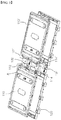
- FIG. 12 is an enlarged view showing portion C of FIG. 10 .
- a battery module 200 is configured to have a structure including unit cells 210 and 210', the unit cell 210 having electrode terminals 212 and 214 formed at one side thereof, the unit cell 210' having electrode terminals 212' and 214' formed at one side thereof, cartridges 220 and 220' for fixing the unit cells 210 and 210', respectively, and busbars 232 and 234 coupled to the electrode terminals 212, 214, 212', and 214' for electrically interconnecting the unit cells 210 and 210'.
- the unit cells 210 and 210' are mounted at the cartridges 220 and 220' such that the electrode terminals 212, 214, 212', and 214' are opposite to each other, and the electrode terminals 212, 214, 212', and 214' are coupled to the busbars 232 and 234 for parallel connection, which are mounted at the cartridges 220 and 220', such that the cartridges 220 and 220' have unit cell parallel connection structures.
- the cartridges 220 and 220' are stacked such that the unit cell parallel connection structures are arranged in a height direction from the ground.
- a series connection member 240 is coupled to the busbars 232 and 234 for parallel connection, which are included in each of the unit cell parallel connection structures.
- Each of the cartridges 220 and 220' is provided at opposite sides thereof with protrusions 222, each of which has a fastening hole 224.
- the cartridges 220 and 220' are fixed in a state in which the cartridges 220 and 220' are stacked by stacking the cartridges 220 and 220' and then inserting fastening members 250 through the fastening holes 224 of the cartridges 220 and 220'.
- the protrusions 222 of the cartridges 220 and 220' are arranged symmetrically with respect to the middle of each cartridge such that the cartridges 220 and 220' are alternately arranged in a state in which a stable coupling structure is provided between the cartridges 220 and 220'.
- FIG. 12 is an enlarged view showing portion C of FIG. 10 .
- one end 235 of a surface of the busbar 234 for parallel connection to which the electrode terminals are coupled is bent downward.
- the series connection member 240 is coupled to the bent end 235 of the busbar 234 for parallel connection.
- the bent end 235 of the busbar 234 for parallel connection is located outside the unit cell parallel connection structures, which are stacked.
- the series connection member 240 interconnects busbars 234 for parallel connection of adjacent unit cell parallel connection structures such that the unit cell parallel connection structures are connected in series to each other.
- Coupling holes 236 are formed at the bent end 235 of the busbar 234 for parallel connection and at one end of the series connection member 240, and bolts, bolts-nuts, or clinching nuts, are electrically and mechanically fastened to the coupling holes.
- a battery module according to the present invention includes a structure in which a plurality of battery cells is connected in parallel to each other to constitute unit cell parallel connection structures, and the unit cell parallel connection structures are stacked in a state in which the unit cell parallel connection structures are connected in parallel to each other. Consequently, it is possible to easily assemble the battery module and to extend the battery module to a parallel structure through a simple process.
- a structure in which some of the unit cell parallel connection structures are connected in series to each other is added to the structure in which the unit cell parallel connection structures are stacked such that the unit cell parallel connection structures are connected in parallel to each other. Consequently, it is possible to easily achieve parallel and/or series combinations, whereby it is possible to easily adjust the capacity and output of the battery module through a simple process.
Claims (16)
- Batteriemodul (100), welches aufweist: Einheitszellen (110), deren jede Elektrodenanschlüsse (112, 114) aufweist, die an deren einen Seite ausgebildet sind, Kassetten (120, 121) zum Befestigen der jeweiligen Einheitszellen (110), sowie Busstangen (132, 134), die mit den Elektrodenanschlüssen (112, 114) verbunden sind, um die Einheitszellen (110) elektrisch miteinander zu verbinden,
wobei die Einheitszellen (110) an den jeweiligen Kassetten (120, 121) derart angebracht sind, dass die Elektrodenanschlüsse (112, 114) einander gegenüberliegen, und die Elektrodenanschlüsse (112, 114) über die Busstangen (132, 134), die an den jeweiligen Kassetten (120, 121) angebracht sind, zur parallelen Verbindung parallel miteinander verbunden sind, so dass die Kassetten (120, 121) parallele Einheitszellen-Verbindungsstrukturen (182, 184, 186, 188) aufweisen,
dadurch gekennzeichnet, dass
die Kassetten (120, 121) derart gestapelt sind, dass die parallelen Einheitszellen-Verbindungsstrukturen (182, 184, 186, 188) in Höhenrichtung vom Boden her angeordnet sind, und die parallelen Einheitszellen-Verbindungsstrukturen (182, 184, 186, 188) über ein serielles Verbindungselement (142) und/oder ein paralleles Verbindungselement (140) elektrisch miteinander verbunden sind, um die parallelen Einheitszellen-Verbindungsstrukturen (182, 184, 186, 188) in Serie und/oder parallel miteinander zu verbinden, und
jede der Einheitszellen (110) eine Einzelplatten-förmige Batteriezelle (10) ist, oder so konfiguriert ist, dass sie eine Struktur hat, in der zwei oder mehr plattenförmige Batteriezellen (10) in einer Zellenabdeckung (116), in einem Zustand angebracht sind, in dem Elektrodenanschlüsse (112, 114) freiliegen. - Das Batteriemodul (100) nach Anspruch 1, wobei die plattenförmige Batteriezelle (10) so konfiguriert ist, dass sie eine Struktur hat, in der eine Elektrodenanordnung in einem Batteriegehäuse angebracht ist, das aus einer Laminatschicht hergestellt ist, die eine Metallschicht und eine Kunststoffschicht aufweist, und ein Außenrand des Batteriegehäuses abgedichtet ist.
- Das Batteriemodul (100) nach Anspruch 1, wobei die Zellenabdeckung (116) ein Paar von Abschirmelementen aufweist, die miteinander verbunden sind, um Außenoberflächen der Batteriezellen (10), ausschließlich der Elektrodenanschlüsse (112, 114), abzudecken.
- Das Batteriemodul (100) nach Anspruch 1, wobei zwei Batteriezellen (10) in der Zellenabdeckung (116) angebracht sind, wobei bevorzugt die zwei Batteriezellen (10) in der Zellenabdeckung (116) derart gestapelt sind, dass Elektrodenanschlüsse (112, 114) mit gleichen Polaritäten parallel miteinander verbunden sind, während sie einander benachbart sind.
- Das Batteriemodul (100) nach Anspruch 1, wobei jede der Kassetten (120, 121) an ihren entgegengesetzten Seiten mit Vorsprüngen (122) versehen sind, deren jeder ein Befestigungsloch (124) aufweist, und die Kassetten (120, 121) miteinander verbunden sind, indem Kassettenbefestigungselemente durch die Befestigungslöcher (124) eingesetzt werden, wobei bevorzugt die Vorsprünge (122), die an den entgegengesetzten Seiten jeder Kassette ausgebildet sind, in Bezug auf eine Mitte jeder Kassette symmetrisch angeordnet sind.
- Das Batteriemodul (100) nach Anspruch 1, wobei die Busstangen (132, 134) zur parallelen Verbindung mit den Kassetten (120, 121) verbunden sind, wobei bevorzugt die Elektrodenanschlüsse der Einheitszellen (110) mit den Busstangen (132, 134) zur parallelen Verbindung durch Laserschweißen oder Ultraschallschweißen verbunden sind.
- Das Batteriemodul (100) nach Anspruch 1, wobei ein Ende einer Oberfläche jeder der Busstangen (132, 134) zur parallelen Verbindung jeder der parallelen Einheitszellen-Verbindungsstrukturen (182, 184, 186, 188), mit der die Elektrodenanschlüsse (112, 114) verbunden sind, aufwärts oder abwärts geknickt ist, und das serielle Verbindungselement (142) mit dem geknickten Ende von jeder der Busstangen (132, 134) zur parallelen Verbindung verbunden ist.
- Das Batteriemodul (100) nach Anspruch 7, wobei Verbindungslöcher an dem geknickten Ende von jeder der Busstangen (132, 134) zur parallelen Verbindung und am einen Ende des seriellen Verbindungselements (142) ausgebildet sind, und Bolzen, Bolzen-Muttern oder Klemmmuttern an den Verbindungslöchern elektrisch und mechanisch befestigt sind.
- Das Batteriemodul (100) nach Anspruch 7, wobei die Busstangen (132, 134) zur parallelen Verbindung eine erste Busstange (132), die mit positiven Elektrodenanschlüssen (112, 114) der Einheitszellen (110) verbunden sind, sowie eine zweite Busstange (134), die mit negativen Elektrodenanschlüssen (112, 114) der Einheitszellen (110) verbunden sind, aufweisen, und die parallelen Einheitszellen-Verbindungsstrukturen (182, 184, 186, 188) derart gestapelt sind, dass die erste Busstange (132) und die zweite Busstange (134) auf Kassetten-weiser Basis abwechselnd angeordnet sind, wobei bevorzugt eine obere Kassette auf eine untere Kassette in einem Zustand gestapelt ist, indem die obere Kassette um 180° in Bezug auf die untere Kassette auf einer Ebene gedreht ist, so dass die erste Busstange (132) und die zweite Busstange (134) abwechselnd angeordnet sind.
- Das Batteriemodul (100) nach Anspruch 1, wobei ein Ende einer Oberfläche von jeder der Busstangen (132, 134) zur parallelen Verbindung jeder der parallelen Einheitszellen-Verbindungsstrukturen (182, 184, 186, 188), mit denen die Elektrodenanschlüsse (112, 114) verbunden sind, aufwärts oder abwärts geknickt ist, und das parallele Verbindungselement (140) und das serielle Verbindungselement (142) mit dem geknickten Ende von jeder der Busstangen (132, 134) zur parallelen Verbindung verbunden sind.
- Das Batteriemodul (100) nach Anspruch 10, wobei Verbindungslöcher am geknickten Ende jeder der Busstangen (132, 134) zur parallelen Verbindung am einen Ende des parallelen Verbindungselements (140) und am einen Ende des seriellen Verbindungselements (142) ausgebildet sind, und Bolzen, Bolzen-Muttern oder Klemmmuttern an den Verbindungslöchern elektrisch und mechanisch befestigt sind.
- Das Batteriemodul (100) nach Anspruch 10, wobei geknickte Enden von zumindest zweien der Busstangen (132, 134) zur parallelen Verbindung über das serielle Verbindungselement (142) seriell miteinander verbunden sind, und zumindest eine der Busstangen (132, 134) zur parallelen Verbindung, die über das serielle Verbindungselement (142) miteinander verbunden sind, mit den verbleibenden Busstangen (132, 134) zur parallelen Verbindung über das parallele Verbindungselement (140) parallel verbunden sind.
- Das Batteriemodul (100) nach Anspruch 12, wobei die Busstangen (132, 134) zur parallelen Verbindung eine erste Busstange (132), die mit positiven Elektrodenanschlüssen (112, 114) der Einheitszellen (110) verbunden ist, sowie eine zweite Busstange (134), die mit negativen Elektrodenanschlüssen (112, 114) der Einheitszellen (110) verbunden ist, aufweisen, und die Busstangen (132, 134) zur parallelen Verbindung, die über das serielle Verbindungselement (142) seriell miteinander verbunden sind, derart gestapelt sind, dass die erste Busstange (132) und die zweite Busstange (134) auf Kassetten-weiser Basis abwechselnd angeordnet sind, wobei bevorzugt eine obere Kassette auf eine untere Kassette in einem Zustand gestapelt ist, indem die obere Kassette in Bezug auf die untere Kassette um 180 Grad auf einer Ebene gedreht ist, so dass die erste Busstange (132) und die zweite Busstange (134) abwechselnd angeordnet sind.
- Das Batteriemodul (100) nach Anspruch 1, wobei die Einheitszellen (110) von jeder der parallelen Einheitszellen-Verbindungsstrukturen (182, 184, 186, 188) an den jeweiligen Kassetten (120, 121) in einem Zustand angebracht sind, in dem die Einheitszellen (110) in Bezug auf die Busstangen (132, 134) zur parallelen Verbindung symmetrisch angeordnet sind, wobei bevorzugt ein externer Eingangs- und Ausgangsanschluss (160), der mit dem seriellen Verbindungselement (142) elektrisch verbunden ist, an einer Seite einer Außenoberfläche der gestapelten parallelen Einheitszellen-Verbindungsstrukturen (182, 184, 186, 188) ausgebildet ist.
- Batteriepack, das ein Batteriemodul (100) nach einem der Ansprüche 1 bis 14 als Einheitsmodul aufweist.
- Vorrichtung, die ein Batteriepack nach Anspruch 15 aufweist.
Applications Claiming Priority (3)
| Application Number | Priority Date | Filing Date | Title |
|---|---|---|---|
| KR1020130100387A KR101747398B1 (ko) | 2013-08-23 | 2013-08-23 | 병렬 연결 구조의 적층형 전지모듈 |
| KR1020130100357A KR101746127B1 (ko) | 2013-08-23 | 2013-08-23 | 직렬 연결 구조의 적층형 전지모듈 |
| PCT/KR2014/007840 WO2015026202A1 (ko) | 2013-08-23 | 2014-08-22 | 연결 구조의 변경이 용이한 적층형 전지모듈 |
Publications (3)
| Publication Number | Publication Date |
|---|---|
| EP3018733A1 EP3018733A1 (de) | 2016-05-11 |
| EP3018733A4 EP3018733A4 (de) | 2016-07-06 |
| EP3018733B1 true EP3018733B1 (de) | 2017-06-14 |
Family
ID=52483915
Family Applications (1)
| Application Number | Title | Priority Date | Filing Date |
|---|---|---|---|
| EP14837524.9A Active EP3018733B1 (de) | 2013-08-23 | 2014-08-22 | Stapelbares batteriemodul mit leicht veränderbarer verbindungsstruktur |
Country Status (3)
| Country | Link |
|---|---|
| US (1) | US10084174B2 (de) |
| EP (1) | EP3018733B1 (de) |
| WO (1) | WO2015026202A1 (de) |
Cited By (1)
| Publication number | Priority date | Publication date | Assignee | Title |
|---|---|---|---|---|
| DE102019112075A1 (de) * | 2019-05-09 | 2020-11-12 | Dr. Ing. H.C. F. Porsche Aktiengesellschaft | Traktionsbatterie für ein Elektrofahrzeug sowie Fertigungsfolge einer solchen Traktionsbatterie |
Families Citing this family (31)
| Publication number | Priority date | Publication date | Assignee | Title |
|---|---|---|---|---|
| JP6416765B2 (ja) | 2012-08-16 | 2018-10-31 | エノビクス・コーポレイションEnovix Corporation | 3次元電池のための電極構造体 |
| KR101686583B1 (ko) | 2013-11-29 | 2016-12-14 | 주식회사 엘지화학 | 카트리지 적층 구조의 전지모듈 |
| US10581039B2 (en) | 2015-04-17 | 2020-03-03 | Ford Global Technologies, Llc | Traction battery assembly |
| US10062931B2 (en) | 2015-04-22 | 2018-08-28 | Johnson Controls Technology Company | Welding process for battery module components |
| US9929388B2 (en) * | 2015-04-23 | 2018-03-27 | Ford Global Technologies, Llc | Traction battery assembly |
| EP3295507B1 (de) | 2015-05-14 | 2020-08-19 | Enovix Corporation | Längsschranken für energiespeichervorrichtungen |
| SG10202106068XA (en) | 2016-05-13 | 2021-07-29 | Enovix Corp | Dimensional constraints for three-dimensional batteries |
| KR102059077B1 (ko) | 2016-06-13 | 2019-12-24 | 주식회사 엘지화학 | 배터리 모듈 및 이를 포함하는 배터리 팩, 자동차 |
| WO2018033880A2 (en) | 2016-08-17 | 2018-02-22 | Shape Corp. | Battery support and protection structure for a vehicle |
| WO2018093965A1 (en) | 2016-11-16 | 2018-05-24 | Enovix Corporation | Three-dimensional batteries with compressible cathodes |
| WO2018127832A1 (en) | 2017-01-04 | 2018-07-12 | Shape Corp. | Vehicle battery tray structure with nodal modularity |
| WO2018213383A1 (en) | 2017-05-16 | 2018-11-22 | Shape Corp. | Vehicle battery tray with integrated battery retention and support features |
| WO2018213306A1 (en) | 2017-05-16 | 2018-11-22 | Shape Corp. | Vehicle battery tray having tub-based component |
| WO2018213475A1 (en) | 2017-05-16 | 2018-11-22 | Shape Corp. | Polarized battery tray for a vehicle |
| CN111108015A (zh) | 2017-09-13 | 2020-05-05 | 形状集团 | 具有管状外围壁的车辆电池托盘 |
| CN107757399A (zh) * | 2017-09-22 | 2018-03-06 | 北京精密机电控制设备研究所 | 一种具有安全管理的电池管理系统 |
| CN111201155A (zh) | 2017-10-04 | 2020-05-26 | 形状集团 | 用于电动车辆的电池托盘底板组件 |
| SG11202004398WA (en) * | 2017-11-15 | 2020-06-29 | Enovix Corp | Electrode assembly, secondary battery, and method of manufacture |
| US10256507B1 (en) | 2017-11-15 | 2019-04-09 | Enovix Corporation | Constrained electrode assembly |
| KR102319537B1 (ko) | 2017-12-20 | 2021-10-29 | 주식회사 엘지에너지솔루션 | 배터리 모듈, 이를 포함하는 배터리 팩 및 자동차 |
| WO2019169080A1 (en) | 2018-03-01 | 2019-09-06 | Shape Corp. | Cooling system integrated with vehicle battery tray |
| US11688910B2 (en) | 2018-03-15 | 2023-06-27 | Shape Corp. | Vehicle battery tray having tub-based component |
| US10784488B2 (en) * | 2018-07-05 | 2020-09-22 | Miklos Bende | Battery assembly |
| US11024915B2 (en) * | 2018-07-05 | 2021-06-01 | Miklos Bende | Battery module adapter |
| US10811648B2 (en) * | 2018-07-05 | 2020-10-20 | Miklos Bende | Housing assembly for battery module |
| US11431052B2 (en) | 2018-07-05 | 2022-08-30 | Miklos Bende | Starter module adapter |
| KR102404239B1 (ko) * | 2018-09-10 | 2022-05-30 | 주식회사 엘지에너지솔루션 | Icb 조립체, 이를 포함한 배터리 모듈 및 그 제조 방법 |
| KR102309630B1 (ko) | 2018-09-10 | 2021-10-05 | 주식회사 엘지에너지솔루션 | Icb 조립체, 이를 포함한 배터리 모듈 및 그 제조 방법 |
| KR102393936B1 (ko) * | 2018-09-10 | 2022-05-03 | 주식회사 엘지에너지솔루션 | Icb 조립체, 이를 포함한 배터리 모듈 및 그 제조 방법 |
| KR102545057B1 (ko) * | 2020-11-12 | 2023-06-20 | 주식회사 성우하이텍 | 배터리의 단자 연결 유닛 |
| JP7470730B2 (ja) | 2022-03-30 | 2024-04-18 | 本田技研工業株式会社 | バッテリパック |
Family Cites Families (14)
| Publication number | Priority date | Publication date | Assignee | Title |
|---|---|---|---|---|
| KR100943833B1 (ko) * | 2005-12-02 | 2010-02-24 | 주식회사 엘지화학 | 중대형 전지팩용 카트리지 |
| KR100921346B1 (ko) | 2006-09-25 | 2009-10-13 | 주식회사 엘지화학 | 중대형 전지모듈 및 전지모듈 어셈블리 |
| WO2008038914A1 (en) | 2006-09-25 | 2008-04-03 | Lg Chem, Ltd. | Cell-module cartridge and mid-large battery module including the same |
| KR100889241B1 (ko) | 2006-10-23 | 2009-03-17 | 주식회사 엘지화학 | 전지모듈의 전극단자 접속부재 |
| KR101051483B1 (ko) | 2008-03-07 | 2011-07-22 | 주식회사 엘지화학 | 전지모듈의 전극단자 접속부재 |
| JP2010257750A (ja) * | 2009-04-24 | 2010-11-11 | Sanyo Electric Co Ltd | バッテリモジュール、バッテリシステムおよび電動車両 |
| US8557411B2 (en) * | 2009-08-14 | 2013-10-15 | Samsung Sdi Co., Ltd. | Secondary battery with a connection tab folded around an insulator and method of manufacturing the same |
| US20130122339A1 (en) * | 2009-11-27 | 2013-05-16 | V-Ens Co., Ltd. | Battery |
| KR101053208B1 (ko) | 2010-02-09 | 2011-08-01 | 주식회사 엘지화학 | 용접 신뢰성이 향상된 전지모듈 및 이를 포함하는 중대형 전지팩 |
| CN103201879B (zh) | 2010-11-22 | 2015-06-03 | 株式会社Lg化学 | 具有紧凑结构的电池组 |
| KR101305224B1 (ko) * | 2010-12-28 | 2013-09-12 | 주식회사 엘지화학 | 전지모듈 및 이를 포함하는 전지팩 |
| DE102011117235A1 (de) | 2011-10-28 | 2013-05-02 | Li-Tec Battery Gmbh | Zellrahmen einer elektrochemischen Zelle, elektrochemische Zelle mit Zellrahmen und Batterie mit entsprechenden elektrochemischen Zellen |
| WO2013089468A1 (ko) | 2011-12-14 | 2013-06-20 | 주식회사 엘지화학 | 신뢰성이 향상된 전지모듈 어셈블리 및 이를 포함하는 중대형 전지팩 |
| CN202839883U (zh) | 2012-09-28 | 2013-03-27 | 比亚迪股份有限公司 | 一种动力电池组 |
-
2014
- 2014-08-22 WO PCT/KR2014/007840 patent/WO2015026202A1/ko active Application Filing
- 2014-08-22 EP EP14837524.9A patent/EP3018733B1/de active Active
- 2014-08-22 US US14/909,813 patent/US10084174B2/en active Active
Non-Patent Citations (1)
| Title |
|---|
| None * |
Cited By (1)
| Publication number | Priority date | Publication date | Assignee | Title |
|---|---|---|---|---|
| DE102019112075A1 (de) * | 2019-05-09 | 2020-11-12 | Dr. Ing. H.C. F. Porsche Aktiengesellschaft | Traktionsbatterie für ein Elektrofahrzeug sowie Fertigungsfolge einer solchen Traktionsbatterie |
Also Published As
| Publication number | Publication date |
|---|---|
| WO2015026202A1 (ko) | 2015-02-26 |
| EP3018733A1 (de) | 2016-05-11 |
| US10084174B2 (en) | 2018-09-25 |
| US20160197332A1 (en) | 2016-07-07 |
| EP3018733A4 (de) | 2016-07-06 |
Similar Documents
| Publication | Publication Date | Title |
|---|---|---|
| EP3018733B1 (de) | Stapelbares batteriemodul mit leicht veränderbarer verbindungsstruktur | |
| EP2833436B1 (de) | Batteriepack mit Struktur zur Montage an der Außenseite | |
| US10897033B2 (en) | Battery pack for electric power storage device | |
| US9997758B2 (en) | Battery module having bus bar assembly and battery pack comprising the same | |
| EP3054503B1 (de) | Batteriemodul mit gestapelten kartuschen | |
| US9768427B2 (en) | Battery module assembly of improved reliability and battery pack employed with the same | |
| EP2988344B1 (de) | Batteriemodul mit neuartiger struktur und batteriepack damit | |
| EP2645454B1 (de) | Sammelschienenblock mit einem neuartigen aufbau | |
| US9960403B2 (en) | Battery module assembly having communication terminals of BMS protruding from front thereof | |
| EP2624334A2 (de) | Batteriepack mit einer kompakten struktur | |
| KR101747398B1 (ko) | 병렬 연결 구조의 적층형 전지모듈 | |
| KR101746127B1 (ko) | 직렬 연결 구조의 적층형 전지모듈 | |
| US9806319B2 (en) | Battery module having ring terminal guide | |
| US10069178B2 (en) | Battery cell having connecting protrusion for voltage sensing and battery module comprising the same |
Legal Events
| Date | Code | Title | Description |
|---|---|---|---|
| PUAI | Public reference made under article 153(3) epc to a published international application that has entered the european phase |
Free format text: ORIGINAL CODE: 0009012 |
|
| 17P | Request for examination filed |
Effective date: 20160202 |
|
| AK | Designated contracting states |
Kind code of ref document: A1 Designated state(s): AL AT BE BG CH CY CZ DE DK EE ES FI FR GB GR HR HU IE IS IT LI LT LU LV MC MK MT NL NO PL PT RO RS SE SI SK SM TR |
|
| AX | Request for extension of the european patent |
Extension state: BA ME |
|
| A4 | Supplementary search report drawn up and despatched |
Effective date: 20160607 |
|
| RIC1 | Information provided on ipc code assigned before grant |
Ipc: H01M 2/02 20060101ALN20160601BHEP Ipc: H01M 2/20 20060101AFI20160601BHEP Ipc: H01M 2/10 20060101ALI20160601BHEP Ipc: H01M 2/26 20060101ALI20160601BHEP Ipc: B60L 11/18 20060101ALI20160601BHEP Ipc: H01M 2/30 20060101ALI20160601BHEP Ipc: H05K 5/00 20060101ALI20160601BHEP |
|
| DAX | Request for extension of the european patent (deleted) | ||
| RIC1 | Information provided on ipc code assigned before grant |
Ipc: H01M 2/20 20060101AFI20170131BHEP Ipc: H05K 5/00 20060101ALI20170131BHEP Ipc: H01M 2/30 20060101ALI20170131BHEP Ipc: B60L 11/18 20060101ALI20170131BHEP Ipc: H01M 2/26 20060101ALI20170131BHEP Ipc: H01M 2/02 20060101ALN20170131BHEP Ipc: H01M 2/10 20060101ALI20170131BHEP |
|
| GRAP | Despatch of communication of intention to grant a patent |
Free format text: ORIGINAL CODE: EPIDOSNIGR1 |
|
| GRAS | Grant fee paid |
Free format text: ORIGINAL CODE: EPIDOSNIGR3 |
|
| GRAJ | Information related to disapproval of communication of intention to grant by the applicant or resumption of examination proceedings by the epo deleted |
Free format text: ORIGINAL CODE: EPIDOSDIGR1 |
|
| GRAL | Information related to payment of fee for publishing/printing deleted |
Free format text: ORIGINAL CODE: EPIDOSDIGR3 |
|
| INTG | Intention to grant announced |
Effective date: 20170406 |
|
| GRAR | Information related to intention to grant a patent recorded |
Free format text: ORIGINAL CODE: EPIDOSNIGR71 |
|
| GRAA | (expected) grant |
Free format text: ORIGINAL CODE: 0009210 |
|
| INTC | Intention to grant announced (deleted) | ||
| RIC1 | Information provided on ipc code assigned before grant |
Ipc: H01M 2/26 20060101ALI20170504BHEP Ipc: B60L 11/18 20060101ALI20170504BHEP Ipc: H01M 2/02 20060101ALN20170504BHEP Ipc: H01M 2/30 20060101ALI20170504BHEP Ipc: H05K 5/00 20060101ALI20170504BHEP Ipc: H01M 2/10 20060101ALI20170504BHEP Ipc: H01M 2/20 20060101AFI20170504BHEP |
|
| AK | Designated contracting states |
Kind code of ref document: B1 Designated state(s): AL AT BE BG CH CY CZ DE DK EE ES FI FR GB GR HR HU IE IS IT LI LT LU LV MC MK MT NL NO PL PT RO RS SE SI SK SM TR |
|
| INTG | Intention to grant announced |
Effective date: 20170509 |
|
| REG | Reference to a national code |
Ref country code: GB Ref legal event code: FG4D |
|
| REG | Reference to a national code |
Ref country code: CH Ref legal event code: EP Ref country code: AT Ref legal event code: REF Ref document number: 901734 Country of ref document: AT Kind code of ref document: T Effective date: 20170615 |
|
| REG | Reference to a national code |
Ref country code: IE Ref legal event code: FG4D |
|
| REG | Reference to a national code |
Ref country code: DE Ref legal event code: R096 Ref document number: 602014010868 Country of ref document: DE |
|
| REG | Reference to a national code |
Ref country code: FR Ref legal event code: PLFP Year of fee payment: 4 |
|
| REG | Reference to a national code |
Ref country code: NL Ref legal event code: MP Effective date: 20170614 |
|
| REG | Reference to a national code |
Ref country code: LT Ref legal event code: MG4D |
|
| PG25 | Lapsed in a contracting state [announced via postgrant information from national office to epo] |
Ref country code: FI Free format text: LAPSE BECAUSE OF FAILURE TO SUBMIT A TRANSLATION OF THE DESCRIPTION OR TO PAY THE FEE WITHIN THE PRESCRIBED TIME-LIMIT Effective date: 20170614 Ref country code: GR Free format text: LAPSE BECAUSE OF FAILURE TO SUBMIT A TRANSLATION OF THE DESCRIPTION OR TO PAY THE FEE WITHIN THE PRESCRIBED TIME-LIMIT Effective date: 20170915 Ref country code: HR Free format text: LAPSE BECAUSE OF FAILURE TO SUBMIT A TRANSLATION OF THE DESCRIPTION OR TO PAY THE FEE WITHIN THE PRESCRIBED TIME-LIMIT Effective date: 20170614 Ref country code: LT Free format text: LAPSE BECAUSE OF FAILURE TO SUBMIT A TRANSLATION OF THE DESCRIPTION OR TO PAY THE FEE WITHIN THE PRESCRIBED TIME-LIMIT Effective date: 20170614 Ref country code: NO Free format text: LAPSE BECAUSE OF FAILURE TO SUBMIT A TRANSLATION OF THE DESCRIPTION OR TO PAY THE FEE WITHIN THE PRESCRIBED TIME-LIMIT Effective date: 20170914 |
|
| REG | Reference to a national code |
Ref country code: AT Ref legal event code: MK05 Ref document number: 901734 Country of ref document: AT Kind code of ref document: T Effective date: 20170614 |
|
| PG25 | Lapsed in a contracting state [announced via postgrant information from national office to epo] |
Ref country code: SE Free format text: LAPSE BECAUSE OF FAILURE TO SUBMIT A TRANSLATION OF THE DESCRIPTION OR TO PAY THE FEE WITHIN THE PRESCRIBED TIME-LIMIT Effective date: 20170614 Ref country code: LV Free format text: LAPSE BECAUSE OF FAILURE TO SUBMIT A TRANSLATION OF THE DESCRIPTION OR TO PAY THE FEE WITHIN THE PRESCRIBED TIME-LIMIT Effective date: 20170614 Ref country code: NL Free format text: LAPSE BECAUSE OF FAILURE TO SUBMIT A TRANSLATION OF THE DESCRIPTION OR TO PAY THE FEE WITHIN THE PRESCRIBED TIME-LIMIT Effective date: 20170614 Ref country code: RS Free format text: LAPSE BECAUSE OF FAILURE TO SUBMIT A TRANSLATION OF THE DESCRIPTION OR TO PAY THE FEE WITHIN THE PRESCRIBED TIME-LIMIT Effective date: 20170614 Ref country code: BG Free format text: LAPSE BECAUSE OF FAILURE TO SUBMIT A TRANSLATION OF THE DESCRIPTION OR TO PAY THE FEE WITHIN THE PRESCRIBED TIME-LIMIT Effective date: 20170914 |
|
| PG25 | Lapsed in a contracting state [announced via postgrant information from national office to epo] |
Ref country code: CZ Free format text: LAPSE BECAUSE OF FAILURE TO SUBMIT A TRANSLATION OF THE DESCRIPTION OR TO PAY THE FEE WITHIN THE PRESCRIBED TIME-LIMIT Effective date: 20170614 Ref country code: AT Free format text: LAPSE BECAUSE OF FAILURE TO SUBMIT A TRANSLATION OF THE DESCRIPTION OR TO PAY THE FEE WITHIN THE PRESCRIBED TIME-LIMIT Effective date: 20170614 Ref country code: EE Free format text: LAPSE BECAUSE OF FAILURE TO SUBMIT A TRANSLATION OF THE DESCRIPTION OR TO PAY THE FEE WITHIN THE PRESCRIBED TIME-LIMIT Effective date: 20170614 Ref country code: SK Free format text: LAPSE BECAUSE OF FAILURE TO SUBMIT A TRANSLATION OF THE DESCRIPTION OR TO PAY THE FEE WITHIN THE PRESCRIBED TIME-LIMIT Effective date: 20170614 Ref country code: RO Free format text: LAPSE BECAUSE OF FAILURE TO SUBMIT A TRANSLATION OF THE DESCRIPTION OR TO PAY THE FEE WITHIN THE PRESCRIBED TIME-LIMIT Effective date: 20170614 |
|
| PG25 | Lapsed in a contracting state [announced via postgrant information from national office to epo] |
Ref country code: IT Free format text: LAPSE BECAUSE OF FAILURE TO SUBMIT A TRANSLATION OF THE DESCRIPTION OR TO PAY THE FEE WITHIN THE PRESCRIBED TIME-LIMIT Effective date: 20170614 Ref country code: ES Free format text: LAPSE BECAUSE OF FAILURE TO SUBMIT A TRANSLATION OF THE DESCRIPTION OR TO PAY THE FEE WITHIN THE PRESCRIBED TIME-LIMIT Effective date: 20170614 Ref country code: PL Free format text: LAPSE BECAUSE OF FAILURE TO SUBMIT A TRANSLATION OF THE DESCRIPTION OR TO PAY THE FEE WITHIN THE PRESCRIBED TIME-LIMIT Effective date: 20170614 Ref country code: SM Free format text: LAPSE BECAUSE OF FAILURE TO SUBMIT A TRANSLATION OF THE DESCRIPTION OR TO PAY THE FEE WITHIN THE PRESCRIBED TIME-LIMIT Effective date: 20170614 Ref country code: IS Free format text: LAPSE BECAUSE OF FAILURE TO SUBMIT A TRANSLATION OF THE DESCRIPTION OR TO PAY THE FEE WITHIN THE PRESCRIBED TIME-LIMIT Effective date: 20171014 |
|
| REG | Reference to a national code |
Ref country code: DE Ref legal event code: R097 Ref document number: 602014010868 Country of ref document: DE |
|
| REG | Reference to a national code |
Ref country code: CH Ref legal event code: PL |
|
| PG25 | Lapsed in a contracting state [announced via postgrant information from national office to epo] |
Ref country code: MC Free format text: LAPSE BECAUSE OF FAILURE TO SUBMIT A TRANSLATION OF THE DESCRIPTION OR TO PAY THE FEE WITHIN THE PRESCRIBED TIME-LIMIT Effective date: 20170614 |
|
| PLBE | No opposition filed within time limit |
Free format text: ORIGINAL CODE: 0009261 |
|
| STAA | Information on the status of an ep patent application or granted ep patent |
Free format text: STATUS: NO OPPOSITION FILED WITHIN TIME LIMIT |
|
| PG25 | Lapsed in a contracting state [announced via postgrant information from national office to epo] |
Ref country code: DK Free format text: LAPSE BECAUSE OF FAILURE TO SUBMIT A TRANSLATION OF THE DESCRIPTION OR TO PAY THE FEE WITHIN THE PRESCRIBED TIME-LIMIT Effective date: 20170614 Ref country code: LI Free format text: LAPSE BECAUSE OF NON-PAYMENT OF DUE FEES Effective date: 20170831 Ref country code: CH Free format text: LAPSE BECAUSE OF NON-PAYMENT OF DUE FEES Effective date: 20170831 |
|
| REG | Reference to a national code |
Ref country code: BE Ref legal event code: MM Effective date: 20170831 |
|
| 26N | No opposition filed |
Effective date: 20180315 |
|
| REG | Reference to a national code |
Ref country code: IE Ref legal event code: MM4A |
|
| PG25 | Lapsed in a contracting state [announced via postgrant information from national office to epo] |
Ref country code: LU Free format text: LAPSE BECAUSE OF NON-PAYMENT OF DUE FEES Effective date: 20170822 |
|
| REG | Reference to a national code |
Ref country code: FR Ref legal event code: PLFP Year of fee payment: 5 |
|
| PG25 | Lapsed in a contracting state [announced via postgrant information from national office to epo] |
Ref country code: IE Free format text: LAPSE BECAUSE OF NON-PAYMENT OF DUE FEES Effective date: 20170822 |
|
| PG25 | Lapsed in a contracting state [announced via postgrant information from national office to epo] |
Ref country code: SI Free format text: LAPSE BECAUSE OF FAILURE TO SUBMIT A TRANSLATION OF THE DESCRIPTION OR TO PAY THE FEE WITHIN THE PRESCRIBED TIME-LIMIT Effective date: 20170614 Ref country code: BE Free format text: LAPSE BECAUSE OF NON-PAYMENT OF DUE FEES Effective date: 20170831 |
|
| PG25 | Lapsed in a contracting state [announced via postgrant information from national office to epo] |
Ref country code: MT Free format text: LAPSE BECAUSE OF NON-PAYMENT OF DUE FEES Effective date: 20170822 |
|
| PG25 | Lapsed in a contracting state [announced via postgrant information from national office to epo] |
Ref country code: HU Free format text: LAPSE BECAUSE OF FAILURE TO SUBMIT A TRANSLATION OF THE DESCRIPTION OR TO PAY THE FEE WITHIN THE PRESCRIBED TIME-LIMIT; INVALID AB INITIO Effective date: 20140822 |
|
| PG25 | Lapsed in a contracting state [announced via postgrant information from national office to epo] |
Ref country code: CY Free format text: LAPSE BECAUSE OF FAILURE TO SUBMIT A TRANSLATION OF THE DESCRIPTION OR TO PAY THE FEE WITHIN THE PRESCRIBED TIME-LIMIT Effective date: 20170614 |
|
| PG25 | Lapsed in a contracting state [announced via postgrant information from national office to epo] |
Ref country code: MK Free format text: LAPSE BECAUSE OF FAILURE TO SUBMIT A TRANSLATION OF THE DESCRIPTION OR TO PAY THE FEE WITHIN THE PRESCRIBED TIME-LIMIT Effective date: 20170614 |
|
| PG25 | Lapsed in a contracting state [announced via postgrant information from national office to epo] |
Ref country code: TR Free format text: LAPSE BECAUSE OF FAILURE TO SUBMIT A TRANSLATION OF THE DESCRIPTION OR TO PAY THE FEE WITHIN THE PRESCRIBED TIME-LIMIT Effective date: 20170614 |
|
| PG25 | Lapsed in a contracting state [announced via postgrant information from national office to epo] |
Ref country code: PT Free format text: LAPSE BECAUSE OF FAILURE TO SUBMIT A TRANSLATION OF THE DESCRIPTION OR TO PAY THE FEE WITHIN THE PRESCRIBED TIME-LIMIT Effective date: 20170614 |
|
| PG25 | Lapsed in a contracting state [announced via postgrant information from national office to epo] |
Ref country code: AL Free format text: LAPSE BECAUSE OF FAILURE TO SUBMIT A TRANSLATION OF THE DESCRIPTION OR TO PAY THE FEE WITHIN THE PRESCRIBED TIME-LIMIT Effective date: 20170614 |
|
| REG | Reference to a national code |
Ref country code: DE Ref legal event code: R079 Ref document number: 602014010868 Country of ref document: DE Free format text: PREVIOUS MAIN CLASS: H01M0002200000 Ipc: H01M0050500000 |
|
| REG | Reference to a national code |
Ref country code: DE Ref legal event code: R081 Ref document number: 602014010868 Country of ref document: DE Owner name: LG ENERGY SOLUTION LTD., KR Free format text: FORMER OWNER: LG CHEM. LTD., SEOUL, KR Ref country code: DE Ref legal event code: R081 Ref document number: 602014010868 Country of ref document: DE Owner name: LG ENERGY SOLUTION, LTD., KR Free format text: FORMER OWNER: LG CHEM. LTD., SEOUL, KR |
|
| P01 | Opt-out of the competence of the unified patent court (upc) registered |
Effective date: 20230512 |
|
| REG | Reference to a national code |
Ref country code: GB Ref legal event code: 732E Free format text: REGISTERED BETWEEN 20230824 AND 20230831 |
|
| PGFP | Annual fee paid to national office [announced via postgrant information from national office to epo] |
Ref country code: GB Payment date: 20230720 Year of fee payment: 10 |
|
| PGFP | Annual fee paid to national office [announced via postgrant information from national office to epo] |
Ref country code: FR Payment date: 20230725 Year of fee payment: 10 Ref country code: DE Payment date: 20230720 Year of fee payment: 10 |
|
| REG | Reference to a national code |
Ref country code: DE Ref legal event code: R081 Ref document number: 602014010868 Country of ref document: DE Owner name: LG ENERGY SOLUTION, LTD., KR Free format text: FORMER OWNER: LG ENERGY SOLUTION LTD., SEOUL, KR |