EP3018489B1 - Anordnung zum erkennen und protokollieren eines durch ferromagneten verursachten vorfalls, zur verwendung mit einem mrt-gerät - Google Patents
Anordnung zum erkennen und protokollieren eines durch ferromagneten verursachten vorfalls, zur verwendung mit einem mrt-gerät Download PDFInfo
- Publication number
- EP3018489B1 EP3018489B1 EP15193190.4A EP15193190A EP3018489B1 EP 3018489 B1 EP3018489 B1 EP 3018489B1 EP 15193190 A EP15193190 A EP 15193190A EP 3018489 B1 EP3018489 B1 EP 3018489B1
- Authority
- EP
- European Patent Office
- Prior art keywords
- arrangement
- access opening
- ferromagnetic
- incident
- set forth
- Prior art date
- Legal status (The legal status is an assumption and is not a legal conclusion. Google has not performed a legal analysis and makes no representation as to the accuracy of the status listed.)
- Active
Links
Images




Classifications
-
- G—PHYSICS
- G01—MEASURING; TESTING
- G01V—GEOPHYSICS; GRAVITATIONAL MEASUREMENTS; DETECTING MASSES OR OBJECTS; TAGS
- G01V3/00—Electric or magnetic prospecting or detecting; Measuring magnetic field characteristics of the earth, e.g. declination, deviation
- G01V3/08—Electric or magnetic prospecting or detecting; Measuring magnetic field characteristics of the earth, e.g. declination, deviation operating with magnetic or electric fields produced or modified by objects or geological structures or by detecting devices
-
- G—PHYSICS
- G01—MEASURING; TESTING
- G01P—MEASURING LINEAR OR ANGULAR SPEED, ACCELERATION, DECELERATION, OR SHOCK; INDICATING PRESENCE, ABSENCE, OR DIRECTION, OF MOVEMENT
- G01P13/00—Indicating or recording presence, absence, or direction, of movement
-
- G—PHYSICS
- G01—MEASURING; TESTING
- G01R—MEASURING ELECTRIC VARIABLES; MEASURING MAGNETIC VARIABLES
- G01R33/00—Arrangements or instruments for measuring magnetic variables
- G01R33/20—Arrangements or instruments for measuring magnetic variables involving magnetic resonance
- G01R33/28—Details of apparatus provided for in groups G01R33/44 - G01R33/64
- G01R33/288—Provisions within MR facilities for enhancing safety during MR, e.g. reduction of the specific absorption rate [SAR], detection of ferromagnetic objects in the scanner room
Definitions
- the present invention is in the field of devices or apparatus for detecting and logging incidents of ferromagnetic objects in or on personnel and equipment in the vicinity of an operating magnetic resonance imaging (MRI) device.
- MRI magnetic resonance imaging
- the large magnetic field of the MRI magnet will attract ferromagnetic objects in the MRI magnet's field of influence. This force of attraction can cause ferromagnetic objects to approach the MRI magnet at high velocity.
- the force of attraction is related to the product of the magnetic field spatial gradient (dB / dz) and the magnetic field strength B.
- Modern MRI machines which have large magnetic fields and steep spatial gradients, can impart a strong force on relatively modest sized objects. It is known, for example, that a hairpin can reach speeds of 40 MPH when released near a typical 1.5 Tesla MRI.
- Ferromagnetic metal detectors provide a means to detect ferromagnetic objects.
- U.S Pat. No. 7,489,128, issued February 10, 2009 to Kopp discloses a special type of Ferromagnetic metal detector that is capable of being located at the doorway of an operable MRI apparatus. The apparatus is capable of providing an alarm to help protect personnel from the problem of ferromagnetic objects knowingly or negligently being brought into the MRI magnet room.
- RCA root cause analysis
- a Blue Ribbon Committee appointed by the American College of Radiology made a number of recommendations based, in part, on the RCA of the above incident.
- the ACR in a White Paper indicated the MRI magnet room should be isolated so that the general public and untrained medical personnel will not have access to the projectile risk associated with the strong magnetic field contained in the MRI magnet room.
- the present invention provides an arrangement for association with an operable MRI apparatus located within a room that has an access opening and with the MRI apparatus providing a residual magnetic field that extends to a location of the access opening.
- the arrangement is also for detecting presence of ferrous material and discriminating out far field magnetic disturbance.
- the arrangement includes a detector configured to passively monitor the residual magnetic field at the location of the access opening.
- the detector includes an array of magnetic field sensors to be arranged about the periphery of the access opening in a spaced arrangement of two spaced apart banks such that each sensor becomes associated with a different portion of the access opening.
- the magnetic field changes in response to a presence of ferrous material at the access opening.
- the magnetic field also changes in response to a far field magnetic disturbance.
- Each of the sensors is configured to output a signal having a value indicative of the sensed magnetic field at the associated portion of the access opening.
- the arrangement includes a corrector configured to correct each signal value from the change in response to the far field magnetic disturbance and to provide respective corrected signal values.
- the corrector includes a summer configured to sum all of said signal values to provide a summed value, a divider configured to divide the summed value by a total number of the magnetic field sensors to provide an average signal value, and a subtractor configured to subtract the average value respectively from each of said signal values to provide the respective corrected signal values.
- the arrangement includes a processor configured to use the corrected signal values to determine whether a ferrous-indicating limit is exceeded and to provide a safety response that addresses the ferrous-indicating limit exceed condition.
- Example embodiments that incorporate one or more aspects of the invention are described and illustrated in the drawings. These illustrated examples are not intended to be a limitation on the invention. For example, one or more aspects of the invention can be utilized in other embodiments and even other types of devices. Moreover, certain terminology is used herein for convenience and ease of identification only and is not to be taken as a limitation on the invention. For example, the terms first, second, etc. are used for convenience and ease of identification only. Still further, in the drawings, the same reference numerals are employed for designating the same elements.
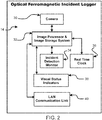
- an overall ferromagnetic incident detecting and logging arrangement 10 is a protection arrangement that is schematically shown within FIG. 1 and includes two principal assemblies, which are: a ferromagnetic detector 12 and an incident recording (or the image processor and storage) system 14.
- the incident recording system 14 is an optical image processor and storage system 14.
- the ferromagnetic detector 12 can be considered to be an augmented ferromagnetic detector 12 because of new inventive aspect(s) of the ferromagnetic detector 12.
- the arrangement 10 is for association with an operable MRI apparatus 20 (represented schematically) located within a room 22 that has an access opening 24 (e.g., a doorway) through one of room-enclosing walls 26 and with the MRI apparatus 20 providing a residual magnetic field that extends to a location of the opening.
- the access opening 24 e.g., doorway
- the arrangement 10, and specifically the ferromagnetic detector 12 thereof is for detecting presence of ferrous material and is also for discriminating out far field magnetic disturbance.
- the arrangement 10, and specifically the image processor and storage system 14 thereof is for recording or logging information/details (e.g., recording images) concerning incidents of detected presence of ferrous material.
- the example image processor and storage system 14 includes a camera 30 that can image with high resolution at a high frame rate.
- the camera 30 can have one or more focusing lenses, one or more image capturing elements (e.g., charge coupled device or CCD), memories, or similar, etc.
- the camera 30 can be equipped with a very wide angle "fish eye" lens and can be mounted in a location with a line of site view of the MRI magnet room 22 as well as the approach to the MRI magnet room via the access opening (e.g., doorway) 24 / door 28..
- the camera 30 can be able to view a status indication of the ferromagnetic detector 12.
- the camera 30 is operatively connected to an image processor and storage system 32 and is operatively controlled by the image processor and storage system 32.
- the image processor and storage system 32 can include one or more of: computers or computing devices, processors or processing devices, controllers controlling devices, hardwired and/or executable programs or the like, and one or more memories, such a RAMs, flash memories, long term memories, or the like.
- the image processor and storage system 32 sends a digital command to the camera 30 periodically to take (i.e., capture) an image. For example, an image could be captured every 0.5 seconds.
- the image processor and storage system 32 stores each image in an image stack of predetermined amount (e.g., "height"). For example, the maximum height of the stack could be 10 images. With a capture rate of 2 images per second, this configuration of the stack could hold 5 seconds worth of images.
- the image processor and storage system 32 can convert the images to a format such as JPEG.
- the image processor and storage system 32 can make adjustments such as contrast, brightness, color depth etc. to optimize image characteristics.
- the continuous replenishment of the image stack is interrupted when an incident is detected by an incident detection monitor 34.
- the incident detection monitor 34 is operatively connected to the image processor and storage system 32.
- the incident detection monitor 34 may also be operatively connected to the ferromagnetic detector 12.
- the image stack is temporarily frozen. No more images are loaded.
- the image processor and storage system 32 can continue to request the camera to acquire more images. However, such images can be stored within other portions of the image processor and storage system 32 (e.g., within a RAM of the image processor and storage system 32).
- a predetermined number of incident-associated images are acquired and specifically stored.
- the predetermined number images could be set to 30. If the images are captured every 0.5 seconds, 15 seconds of data is stored. In this example, a total of 20 seconds of data is being held. In one specific example, the specifically stored images could be for 5 seconds before the incident was detected, and 15 seconds after the incident was detected.
- the image set is stored in a non-volatile memory such as an SD card.
- the image set can be stored in a unique folder with a date and with a time stamp.
- the time and date information can obtained from a real time clock 36.
- the clock 36 is operatively connected to the image processor and storage system 32.
- the storage folder as such is tied uniquely to a specific incident which occurred at a specific identified time.
- images capturing the events which lead up to the incidents are captured. For example, if the incident is a person approaching the door with a ferrous object, images of the approach of the person to the door 28 are captured. In addition, the reaction to the incident is also captured. Concerning the example of the person approaching the door 28, if the person logically does not proceed through the door 28 into the room 22 but instead logically retreats away from the door, images of the logical reaction of retreating away from the door are captured.
- the camera 30 and the image processor and storage system 32 are also able to capture and store associated audio.
- associated audio can be captured and stored concerning/correlating to the captured images of the incident.
- the camera 30 may be able to also view a status indication of the ferromagnetic detector 12. So, the coincident audio and possibly a visual alarm from the augmented ferromagnetic detector array can also be captured.
- the number of images captured as well as the time lapse between captured images can be varied as the situation dictates. In like manner, a video stream could also be captured for a period of time before and after the detected incident.
- the image processor and storage system 32 resumes filling the image stack with new images.
- the image processor and storage system 32 is re-activated to look for a signal from the incident detection monitor 34.
- the incident detection monitor 34 can be operatively coupled to the augmented ferromagnetic detector 12 ( FIG. 1 ).
- This coupling can take many forms such as acoustic, infrared, WIFI, wired (e.g., serial port), etc.
- the incident detection monitor 34 could have a piezoelectric sensor tuned the same frequency as an audible/audio (i.e., sound) alarm indication from the augmented ferromagnetic detector 12 so as to provide the operative coupling.
- the incident detection monitor 34 will respond to an audible/audio indication signal of the tuned frequency and with the specific characteristics of number and duration of beeps from the audible/audio alarm of the augmented ferromagnetic detector 12.
- This example configuration (i.e., use of audible/audio signal) does not require any physical connection between the portion(s) (e.g., the image processor and storage system 32 and/or the incident detection monitor) of the image processor and storage system 14 and the portion(s) of the ferromagnetic detector 12.
- the image processor and storage system 14 should be mounted outside of the MRI room (e.g., on the outside of the wall 26, possibly above/at the doorway 24).
- the augmented ferromagnetic detector 12 FIG. 1
- communication between the image processor and storage system 14 ( FIGS. 1 and 2 ) and the augmented ferromagnetic detector 12 ( FIG. 1 ) is preferably implemented without wires.
- Such an implemented without wires i.e., wireless implementation
- a visual status indicator 38 can be operatively connected to the image processor and storage system 32 within the image processor and storage system 14.
- the visual status indicator 38 can contain indicators (e.g., lights) which can indicate: that the power is ON, that it is time to download the accumulated image incident folders, that the non-volatile image store memory is nearly full, and/or that the non-volatile image store memory is full. Other indicator functions can also be added.
- a LAN communication link 40 can be provided within the image processor and storage system 14.
- the LAN communication link 40 can allow the data to be accessed for further analysis. This analysis will be described later.
- the data can be accessed by a USB port, an HDMI port or other communications means.
- a removable SD card or other non-volatile media can be used to gain access to the stored image data.
- ferromagnetic detector 12 that responds to a ferromagnetic incident is the MRI Protector invention described in. U.S Pat. No. 7,489,128 (European counterpart No. 1482832 , Japanese counterpart No. No. 5,602,160 ), but with augmentation which allows the invention to capture only incidents and not extraneous ferromagnetic events.
- the ferromagnetic detector 12 can include one or more of: computers or computing devices, processors or processing devices, controllers controlling devices, hardwired and/or executable programs or the like, and one or more memories, such a RAMs, flash memories, long term memories, or the like.
- FIG. 8 is a schematic illustration of one example detector 12 of the arrangement 10 that provides for some example augmentations.
- ferromagnetic objects entering/attempting to enter the MRI room 22 should be reported as incidents since these objects pose a projectile threat if present within the MRI room.
- Ferromagnetic objects leaving the MRI room should not be reported as a threat since the projectile risk diminishes with distance from the MRI magnet.
- stray influence, such as far field effects from ferromagnetic objects (possible large ferromagnetic objects) that are not entering/attempting to enter the MRI room 22 should not be reported as incidents since these objects do not pose a projectile threat within the MRI room 22.
- a two-part photoelectric emitter / detector arrangement 50 is mounted in a sensor array 52 of the ferromagnetic detector 12.
- the photoelectric emitter / detector arrangement 50 is located at/near a bottom of the sensor array 52 of the ferromagnetic detector 12.
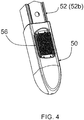
- FIG. 3 an enlarged view of a portion of an example photoelectric emitter / detector arrangement 50 is shown.
- the example includes two (i.e., a pair) photoelectric emitter-detectors 54.
- the pair of photoelectric emitter-detectors 54 are mounted in the sensor array 52 (e.g., at a bottom of a first bank 52a of the sensor array 52) for location at one side of the access opening 24.
- a reflector 56 which is a complementary component to the pair photoelectric emitter-detectors 54 shown within FIG. 3 , is mounted in the sensor array 52 (e.g., at a bottom of a second bank 52b of the sensor array 52) for location at a second side of the access opening 24.
- FIG. 5 illustrates the complete two-part photoelectric emitter / detector arrangement 50, which has direction sensing capability.
- the example emitter-receiver detectors 54 are mounted in the first bank 52a of the sensor array 52 and the reflector 56 is mounted in the second bank 52b of sensor array.
- a photoelectric beam 60/62 is directed from each photoelectric emitter-detector 54 toward the reflector 56, to be reflected back toward the respective photoelectric emitter-detector.
- the photoelectric emitter / detector arrangement 50 is associated with direction sensing capability.
- the photoelectric beam 60 further away from the MRI room 22 will be broken first, followed by the photoelectric beam 62 closest to the MRI room being broken.
- This sequence of events allows the augmented ferromagnetic detector array to look for a ferromagnetic incident and respond; which may be audio and/or visual and/or electrical should a ferromagnetic object pass through the array.
- the remaining photoelectric beam will continue to inhibit incident recording if the remaining beam is not broken. Further, if both beams fail or are misaligned, the augmented ferromagnetic detector array will be continuously active.
- FIG. 8 provided a schematic representation of structures, components, functions, etc. that can accomplish the above mentioned direction sensing capability.
- a computer (or the like) 70 of the detector 12 receives signals from the photoelectric emitter / detector arrangement 50.
- a processor 72 and/or a direction sensing component/function/program 74 of the computer 70 process information provided by the signals from the photoelectric emitter / detector arrangement 50 to make the above mentioned directionality determinations. Also, the computer 70, and the processor 72 thereof, utilized the above mentioned directionality determinations.
- a special far field cancelling function/scheme is implemented in the augmented ferromagnetic detector 12.
- This cancelling function/scheme is a correction, in that the correction is to correctly assess potential threats.
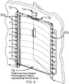
- An example of component/function/program for providing such correction is shown within the example detector of Fig. 8 . The effect and the implementation of this scheme are illustrated in FIG. 6 .
- a large object at a significant distance from the augmented ferromagnetic detector array will produce a nearly identical effect on all (e.g., 12 within the shown example) magnetic sensors in the left bank 52a.
- This uniform magnetic field disturbance is indicated by the equally spaced dashed lines 78.
- a nearly identical effect, but potentially a little different from the effect upon left bank 52a will be produced in all (e.g., 12 within the shown example) magnetic sensors in right bank 52b.
- the computer 70 and/or the processor 72, etc. within the augmented ferromagnetic detector 12 provides the correction.
- the computer has a corrector 80.
- the corrector 80, and portions therein, can be hard-wired components, an executable program possibly performed by the processor 72, etc.
- a summer 82 sums the signal values from each of the sensors in a bank (e.g., 52a). Also within the corrector 80, a divider 84 divides the sum value by the number of sensors in the bank (e.g., 52a, in this case divide by 12). Such division provides an average. Still further within the corrector 80, a subtracter 86 subtracts the average from each signal value so as to remove an average from each signal value. So, the computer 70, processor 72, etc. within the augmented ferromagnetic detector 12 has structured component(s), program(s), etc. that provide the summation of the signal values and (e.g., the summer 82) within the augmented ferromagnetic detector 12.
- This calculated value for each sensor bank will be subtracted from each of the sensor signal output of the respective sensor bank before the computer determines whether an alarm condition is present. This calculation removes the effect of a far field magnetic disturbance of an object at a significant distance and as a result, no alarm event is triggered for the object at a significant distance.
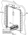
- a ferromagnetic object 90 passing through the ferromagnetic sensor array 52 will produce a very localized magnetic field disturbance effect.
- This effect is illustrated by the cluster of magnetic field lines 92 shown near the bottom of the sensor array 52. All of the magnetic sensors of both banks 52a and 52b, will experience at least some effect from the near field object 90. However, the effect of a nearby ferromagnetic object decreases at approximately the cube of the distance. As a result only sensors near the object 90 will be subjected to a much more significant disturbance than the sensors further away from the object 90. The resulting far field calculation described in the paragraph above does not produce a meaningful reduction of the magnetic disturbance signal of the sensors near the object 90.
- the object will trigger an alarm 94 (see FIG. 8 ) and as such will generate a ferromagnetic incident.
- the alarm 94 can include one or more portions that provide an audible alarm indication and/or a visible alarm indication. Portion(s) that provide the visible alarm indication may be located adjacent/along the extent of the sensor array 52 (e.g., adjacent/along the sensor banks 52a, 52b). It is to be recalled that the incident detection monitor 34 could have a piezoelectric sensor tuned the same frequency as the audible alarm.
- FIG. 1 Another source of magnetic disturbance which is indicative of a ferromagnetic event is the opening (or closing) of the MRI room door.
- the door 28 to the MRI room 22 is shown swinging into the MRI room.
- This door 28 is part of the RF shielding of all operational MRI machines.
- the door is electrically conductive.
- many doors contain ferromagnetic material such as dead bolt locks, hinges and other structural members.
- the door 28 will begin to move and the photoelectric beam(s) 60, 62 will be broken. Since the act of opening the door 28 will move the door though the magnetic spatial gradient generated by the MRI magnet, an eddy current will be produced in the door. This eddy current will produce a magnetic field. The eddy current magnetic field will be detected by the augmented ferromagnetic detector 12 and could trigger the alarm 94. This alarm indication could occur whether the personnel entering the room are carrying ferromagnetic material or not. As a consequence, the resulting alarm indication does not provide useful information as to the ferromagnetic status of the personnel entering the MRI room.
- the augmented ferromagnetic detector array incorporates a door position sensor 100.
- This sensor 100 can be of a variety of types such as a mechanical limit switch, a photoelectric proximity switch or many other types.
- the sensor 100 detects when the door 28 begins to move.
- the computer 70, and/or components therein, of the augmented ferromagnetic detector 12 no longer analyzes the signals from the magnetic sensor banks 52a and 52a. Such can be accomplished via specific component(s) of the computer, hard-wired processing, program processing, or the like.
- the computer 70 reviews the scans of the sensor banks immediately preceding the door position sensor detected door movement to determine whether the approaching person or object had ferromagnetic content sufficient to trigger an alarm. If the ferromagnetic content is sufficient to trigger an alarm indication, the alarm 94 will be activated and a ferromagnetic incident will be recorded when the dual photoelectric beam 60, 62 is broken.
- the computer will once again detect that the door is being opened from the door position sensor 100.
- the signals from the magnetic sensor banks 52a and 52b will be ignored once motion is detected from the door position sensor 100.
- the computer will again analyze the magnetic sensor data from the sensor banks 52a and 52b and determine there was no significant magnetic disturbance immediately before the commencement of the door opening.
- the computer 70 can be programmed (component/hardwired configured) to not generate an alarm indication under these circumstances. As a result, in this situation, no ferromagnetic incident will be logged even though the movement of the MRI room door likely generated a significant magnetic disturbance.
- the door position switch 100 can serve two functions. The first function being the above mentioned sensor function and the second function being a switch to remove power from the entire array when the MRI room door is closed (see dashed control line within FIG. 8 extending from the door position sensor/switch 100 to the sensor array 52. This is desirable since for outswing doors, the augmented ferromagnetic detector array is typically mounted inside of the MRI room. Removing power assures that there is no possibility of interference with the imaging process.
- the door position sensor/switch 100 also allows the MRI door movement to be ignored and as such, the resultant alarm indication potential is eliminated. However, if there is ingress by an object or personnel while the MRI door is moving, an alarm will sound and an incident will be recorded since this would be a violation of established protocol.
- the visual status indicator 38 provides information as to whether the power is ON.
- the indicator 38 also alerts staff that it is time to perform the periodic download of the incident image folders.
- Indicators are also provided to alert staff that the memory containing the incident image folders are nearly full or that the memory is full.
- the incident image folder data can be downloaded through a USB port, an HDMI port or other communications means.
- a preferred method to download the data uses an Ethernet connection to the healthcare facilities local area network 40. With this method a host computer can automatically download the data from the ferromagnetic incident logging manager at will. The data can then be processed to provide information regarding ferromagnetic incident trends. The data can be further analyzed to perform a Root Cause Analysis if appropriate.
- the apparatus described above logs ferromagnetic material attempting entry into the MRI room. Yet ferromagnetic disturbances which do not pose a projectile threat are not logged.
- the apparatus described above is representative of a preferred implementation of the invention. However there are many variations that could be realized by someone trained in the art.
- the arrangement is also for detecting presence of ferrous material and discriminating out far field magnetic disturbance.
- the arrangement includes a detector configured to passively monitor the residual magnetic field at the location of the opening.
- the detector includes an array of magnetic field sensors arranged about the periphery of the opening in a spaced arrangement such that each sensor is associated with a different portion of the access opening.
- the magnetic field changes in response to a presence of ferrous material at the opening.
- the magnetic field also changes in response to a far field magnetic disturbance.
- Each of the sensors is configured to output a signal having a value indicative of the sensed magnetic field at the associated portion of the access opening.
- the arrangement includes a corrector configured to correct each signal value from the change in response to the far field magnetic disturbance and to provide respective corrected signal values.
- the arrangement includes a processor configured to use the corrected signal values to determine a ferrous-indicating limit is exceeded and to provide a safety response that addresses the ferrous-indicating limit exceed condition.
- the arrangement further including a recording system configured to record incident information associated with a determination that a ferrous-indicating limit is exceeded.
- the recording system including a portion configured to record an image of the location of the access opening associated with a determination that a ferrous-indicating limit is exceeded.
- the processor is configured to determine whether an incident occurs upon the ferrous-indicating limit being exceeded and the recording system includes an incident detection monitor configured to cause the recording system to record the incident information upon the processor determining an incident occurrence.
- the detector includes an alarm configured to provide an alarm indication in response to the processor providing the safety response
- the recording system includes a camera configured to capture of an image area that includes the location of the access opening and a least a portion of the alarm that provides the alarm indication.
- the recording system is operatively coupled to the detector.
- the detector includes an alarm configured to provide an audible alarm indication in response to the processor providing the safety response, and the recording system for recording system is operatively coupled to the alarm.
- the operative coupling between the alarm and the recording system is an audible sound coupling.
- the corrector includes: a summer configured to sum all of signal values to provide a summed value, a divider configured to divide the summed value by a total number of the magnetic field sensors to provide an average signal value, and a subtracter configured to subtract the average value respectively from each signal values to provide the respective corrected signal values.
- the access opening is a doorway having a movable door thereat, the arrangement including a direction sensing arrangement configured to determine movement direction of the door.
- the processor is configured to modifying the safety response as a function of the determined movement direction of the door.
- the direction sensing arrangement includes at least one photoelectric emitter-detector device.
- the access opening permits movement of an object there through, the arrangement including a direction sensing arrangement configured to determine movement direction of the object.
- the processor is configured to modifying the safety response as a function of the determined movement direction of the object.
- the direction sensing arrangement includes at least one photoelectric emitter-detector device.
- the object is a person.
- the access opening permits an object to be present at the access opening, the arrangement including a presence sensing arrangement configured to determine presence of the object at the access opening.
- the processor is configured to modifying the safety response as a function of the determined presence of the object.
- the presence sensing arrangement includes at least one photoelectric emitter-detector device.
- the object is a person.
- a magnetic resonance compatible apparatus capable of detecting and recording the occurrence of ferromagnetic objects entering the MRI room.
- the apparatus includes an optical ferromagnetic incident logger and an augmented ferromagnetic detector array.
- the optical ferromagnetic incident logger is activated by the specially augmented ferromagnetic detector array when a ferromagnetic object attempts to enter the MRI magnet room and visually records images immediately before the attempted entry as well as immediately after the incident.
- the optical ferromagnetic image logger has a continuously updated historical image stack.
- the optical ferromagnetic image logger captures images before and after a ferromagnetic incident is detected.
- the optical ferromagnetic image logger captures images on the approach to the MRI door and after passing through the doorway of the MRI doorway.
- the optical ferromagnetic image logger communicates with and captures a ferromagnetic incident from the augmented ferromagnetic detector array.
- the incident image set is stored in a date and time stamped electronic folder.
- the optical ferromagnetic image logger provides an output through a local area network or other communication link to periodically download and analyze the visual incident history.
- the augmented ferromagnetic detector array suppresses potential alarms from objects at a significant distance by ignoring the common mode signal on each bank of sensors.
- the augmented ferromagnetic detector array incorporates a door position switch which provides for the suppression of the detected ferromagnetic disturbance from the moving MRI door but allows the detection of a person or object approaching and opening the MRI door.
Landscapes
- Physics & Mathematics (AREA)
- General Physics & Mathematics (AREA)
- Engineering & Computer Science (AREA)
- Remote Sensing (AREA)
- Life Sciences & Earth Sciences (AREA)
- Condensed Matter Physics & Semiconductors (AREA)
- Electromagnetism (AREA)
- Environmental & Geological Engineering (AREA)
- Geology (AREA)
- General Life Sciences & Earth Sciences (AREA)
- Geophysics (AREA)
- Magnetic Resonance Imaging Apparatus (AREA)
Claims (13)
- Anordnung (10) zur Verbindung mit einem bedienbaren MRI-Gerät (20), das in einem Raum (22) liegt, der eine Zugangsöffnung (24) aufweist und wobei das MRI-Gerät ein Restmagnetfeld bereitstellt, das sich zu einer Position der Zugangsöffnung erstreckt, und um die Gegenwart von eisenhaltigem Material zu erkennen und um magnetische Fernfeldstörung zu auszugrenzen, wobei die Anordnung Folgendes umfasst:einen Detektor (12), der konfiguriert ist, um das Restmagnetfeld an der Position der Zugangsöffnung passiv zu überwachen, wobei der Detektor eine Reihe von Magnetfeldsensoren (52) enthält, die um den Umfang der Zugangsöffnung herum in einer beabstandeten Anordnung von zwei räumlich beabstandeten Reihen (52a, 52b) derart anzuordnen sind, dass jeder Sensor mit einem anderen Abschnitt der Zugangsöffnung verbunden wird, wobei jeder der Sensoren konfiguriert ist, um ein Signal mit einem Wert auszugeben, der das erkannte Magnetfeld an dem assoziierten Abschnitt der Zugangsöffnung anzeigt, wobei sich das Magnetfeld als Reaktion auf eine Gegenwart von eisenhaltigem Material an der Zugangsöffnung, aber auch als Reaktion auf eine magnetische Fernfeldstörung ändern kann;dadurch gekennzeichnet, dass die Anordnung ferner Folgendes umfassen:einen Korrektor (80), der konfiguriert ist, um jeden Signalwert aus der Veränderung als Reaktion auf die magnetische Fernfeldstörung zu korrigieren und um jeweils korrigierte Signalwerte bereitzustellen, wobei der Korrektor Folgendes enthält:einen Summierer (82), der konfiguriert ist, um alle Signalwerte zu summieren, um einen summierten Wert bereitzustellen,einen Teiler (84), der konfiguriert ist, um den summierten Wert durch eine Gesamtanzahl der Magnetfeldsensoren zu teilen, um einen durchschnittlichen Signalwert bereitzustellen, undeinen Subtrahierer (86), der konfiguriert ist, um den Durchschnittswert jeweils von jedem der Signalwerte zu subtrahieren, um die jeweiligen korrigierten Signalwerte bereitzustellen; undeinen Prozessor (72), der konfiguriert ist, um die korrigierten Signalwerte zu verwenden, um festzustellen, ob ein Eisen anzeigender Grenzwert überschritten ist, und um eine Sicherheitsreaktion bereitzustellen, die die Überschreitungsbedingung des Eisen anzeigenden Grenzwerts regelt.
- Anordnung nach Anspruch 1, wobei die Anordnung ferner ein Aufzeichnungssystem enthält, das konfiguriert ist, um Vorfallsinformation aufzuzeichnen, die mit einer Feststellung, dass ein Eisen anzeigender Grenzwert überschritten ist, verbunden ist.
- Anordnung nach Anspruch 2, wobei der Prozessor konfiguriert ist, um festzustellen, ob ein Vorfall stattfindet, wenn der Eisen anzeigende Grenzwert überschritten ist und wobei das Aufzeichnungssystem einen Vorfallserkennungsmonitor beinhaltet, der konfiguriert ist, um zu bewirken, dass das Aufzeichnungssystem die Vorfallsinformation aufzeichnet, wenn der Prozessor ein Auftreten eines Vorfalls feststellt.
- Anordnung nach Anspruch 2, wobei der Detektor einen Alarm enthält, der konfiguriert ist, um eine Alarmanzeige als Reaktion auf den Prozessor bereitzustellen, der eine Sicherheitsreaktion bereitstellt, und wobei das Aufzeichnungssystem eine Kamera (30) enthält, die konfiguriert ist, um einen Bildbereich aufzunehmen, der die Position der Zugangsöffnung und mindestens einen Abschnitt des Alarms enthält, der die Alarmanzeige bereitstellt.
- Anordnung nach Anspruch 2, wobei der Detektor einen Alarm enthält, der konfiguriert ist, um eine akustische Alarmanzeige als Reaktion auf den Prozessor bereitzustellen, der die Sicherheitsreaktion bereitstellt, und wobei das Aufzeichnungssystem mit dem Alarm wirkungsgekoppelt ist.
- Anordnung nach Anspruch 5, wobei es sich bei der Wirkungskopplung zwischen dem Alarm und dem Aufzeichnungssystem um eine akustische Tonkopplung handelt.
- Anordnung nach 1, wobei es sich bei der Zugangsöffnung um einen Eingang mit einer beweglichen Tür (28) daran handelt, wobei die Anordnung eine richtungserkennende Anordnung enthält, die konfiguriert ist, um die Bewegungsrichtung der Tür festzustellen.
- Anordnung nach 7, wobei der Prozessor konfiguriert ist, um die Sicherheitsreaktion in Abhängigkeit von der festgestellten Bewegungsrichtung der Tür zu verändern.
- Anordnung nach 7, wobei die richtungserkennende Anordnung mindestens eine photoelektrische Emitter-Detektor-Vorrichtung enthält.
- Anordnung nach 1, wobei die Zugangsöffnung die Bewegung eines Objekts durch sie hindurch erlaubt, wobei die Anordnung eine richtungserkennende Anordnung enthält, die konfiguriert ist, um die Bewegungsrichtung des Körpers festzustellen.
- Anordnung nach 10, wobei der Prozessor konfiguriert ist, um die Sicherheitsreaktion in Abhängigkeit von der festgestellten Bewegungsrichtung des Objekts zu verändern.
- Anordnung nach 10, wobei die richtungserkennende Anordnung mindestens eine photoelektrische Emitter-Detektor-Vorrichtung (54) enthält.
- Anordnung nach 1, wobei es die Zugangsöffnung erlaubt, dass ein Objekt an der Zugangsöffnung anwesend ist, wobei die Anordnung eine anwesenheitserkennende Anordnung enthält, die konfiguriert ist, um die Anwesenheit des Objekts an der Zugangsöffnung festzustellen, und wobei der Prozessor konfiguriert ist, um die Sicherheitsreaktion in Abhängigkeit von der festgestellten Anwesenheit eines Objekts zu verändern.
Applications Claiming Priority (2)
| Application Number | Priority Date | Filing Date | Title |
|---|---|---|---|
| US201462076079P | 2014-11-06 | 2014-11-06 | |
| US14/882,919 US9651701B2 (en) | 2014-11-06 | 2015-10-14 | Ferromagnetic incident detecting and logging arrangement |
Publications (2)
| Publication Number | Publication Date |
|---|---|
| EP3018489A1 EP3018489A1 (de) | 2016-05-11 |
| EP3018489B1 true EP3018489B1 (de) | 2017-07-12 |
Family
ID=54477877
Family Applications (1)
| Application Number | Title | Priority Date | Filing Date |
|---|---|---|---|
| EP15193190.4A Active EP3018489B1 (de) | 2014-11-06 | 2015-11-05 | Anordnung zum erkennen und protokollieren eines durch ferromagneten verursachten vorfalls, zur verwendung mit einem mrt-gerät |
Country Status (3)
| Country | Link |
|---|---|
| US (1) | US9651701B2 (de) |
| EP (1) | EP3018489B1 (de) |
| JP (1) | JP6692144B2 (de) |
Families Citing this family (8)
| Publication number | Priority date | Publication date | Assignee | Title |
|---|---|---|---|---|
| US7553295B2 (en) | 2002-06-17 | 2009-06-30 | Iradimed Corporation | Liquid infusion apparatus |
| US8105282B2 (en) | 2007-07-13 | 2012-01-31 | Iradimed Corporation | System and method for communication with an infusion device |
| GB2556926A (en) * | 2016-11-25 | 2018-06-13 | Metrasens Ltd | Monitoring system for a detection system |
| US11268506B2 (en) | 2017-12-22 | 2022-03-08 | Iradimed Corporation | Fluid pumps for use in MRI environment |
| US12287309B2 (en) * | 2020-09-10 | 2025-04-29 | Shimadzu Corporation | Wire rope inspection device and wire rope inspection system |
| DE102021209665A1 (de) * | 2021-09-02 | 2023-03-02 | Siemens Healthcare Gmbh | Physiologisches Erfassungssystem zur Verwendung in einem HF-abgeschirmten Raum |
| EP4402517B1 (de) | 2021-09-17 | 2025-09-03 | Iradimed Corporation | Ferromagnetischer detektor und bedrohungsanalyse |
| KR102586287B1 (ko) * | 2023-03-10 | 2023-10-10 | 대한실드엔지니어링(주) | 자성체 금속검출 기능을 가진 mri 전자파 실드도어 |
Family Cites Families (9)
| Publication number | Priority date | Publication date | Assignee | Title |
|---|---|---|---|---|
| US3697972A (en) * | 1969-06-26 | 1972-10-10 | Yull Brown | Metal detection and alarm systems |
| US8148989B2 (en) | 2002-03-11 | 2012-04-03 | Keith Kopp | Ferromagnetic detection enhancer compatible with magnetic resonance |
| US7489128B2 (en) * | 2002-03-11 | 2009-02-10 | Kopp Keith A | MRI protector |
| GB2395276B (en) * | 2002-11-12 | 2006-03-08 | Qinetiq Ltd | Ferromagnetic object detector |
| US20060022670A1 (en) * | 2004-07-31 | 2006-02-02 | Mednovus, Inc. | Magnetic resonance screening portal with combination sensing |
| JP2010025599A (ja) * | 2008-07-15 | 2010-02-04 | Deed Corp | 磁性体検知機 |
| GB201013992D0 (en) | 2010-08-20 | 2010-10-06 | Metrasens Ltd | Apparatus for detecting ferromagnetic objects and a protected doorway assembly |
| GB201219097D0 (en) * | 2012-10-24 | 2012-12-05 | Metrasens Ltd | Apparatus for detecting ferromagnetic objects at a protected doorway assembly |
| JP6071617B2 (ja) * | 2013-02-19 | 2017-02-01 | 東芝メディカルシステムズ株式会社 | 危険物警告システム及び磁気共鳴イメージング装置 |
-
2015
- 2015-10-14 US US14/882,919 patent/US9651701B2/en active Active
- 2015-10-28 JP JP2015211811A patent/JP6692144B2/ja active Active
- 2015-11-05 EP EP15193190.4A patent/EP3018489B1/de active Active
Non-Patent Citations (1)
| Title |
|---|
| None * |
Also Published As
| Publication number | Publication date |
|---|---|
| US9651701B2 (en) | 2017-05-16 |
| US20160131788A1 (en) | 2016-05-12 |
| JP2016087459A (ja) | 2016-05-23 |
| JP6692144B2 (ja) | 2020-05-13 |
| EP3018489A1 (de) | 2016-05-11 |
Similar Documents
| Publication | Publication Date | Title |
|---|---|---|
| US9651701B2 (en) | Ferromagnetic incident detecting and logging arrangement | |
| US10191176B2 (en) | Door assembly for an MRI room | |
| US10109177B2 (en) | Apparatus for detecting ferromagnetic objects at a protected doorway assembly | |
| US8953045B2 (en) | Automated teller machine comprising at least one camera to detect manipulation attempts | |
| CN102598072B (zh) | 包括产生图像数据以检测操纵尝试的至少一个摄像机的自动出纳机 | |
| JP5360175B2 (ja) | 自動取引装置 | |
| KR102305704B1 (ko) | 어류의 질병여부를 판단하고 포획할 수 있는 어류질병 감지장치 | |
| US20120038772A1 (en) | Automated teller machine comprising camera to detect manipulation attempts | |
| CN109410401A (zh) | 适用于智慧小区的人脸识别门禁管理系统 | |
| CN108271082A (zh) | 在视频管理系统中基于注视的警报屏蔽 | |
| KR101454644B1 (ko) | 보행자 추적기를 이용한 서성거림을 탐지하는 방법 | |
| CA3009681A1 (en) | Method to detect the possible threat/attack in atm by extracting deviations in atm door/shutter status and alerting cms and first responders | |
| CN210377675U (zh) | 智能医药柜 | |
| KR101524922B1 (ko) | 비상 알림을 위한 장치, 방법 및, 기록 매체 | |
| US9715794B2 (en) | POS system and method for operating a POS system | |
| CN207530963U (zh) | 一种基于视频监控的非法越界报警系统 | |
| JP5757708B2 (ja) | 通報装置 | |
| JP2020510454A (ja) | 検出システム用の監視システム | |
| CN112016509A (zh) | 人员站位异常提醒方法及装置 | |
| CN111095370A (zh) | 用于机架式机箱的侵入检测的系统和方法 | |
| CN107123206A (zh) | 金融行业通讯设备智能管控系统与方法 | |
| CN207352683U (zh) | 一种用于重要场所出入口的吊闸控制系统 | |
| CN106791541A (zh) | 智能影像式监测告警装置 | |
| JP6761328B2 (ja) | 集合住宅用インターホンシステム | |
| JP2008160617A (ja) | 監視カメラ装置及びこれを用いた監視カメラシステム |
Legal Events
| Date | Code | Title | Description |
|---|---|---|---|
| PUAI | Public reference made under article 153(3) epc to a published international application that has entered the european phase |
Free format text: ORIGINAL CODE: 0009012 |
|
| AK | Designated contracting states |
Kind code of ref document: A1 Designated state(s): AL AT BE BG CH CY CZ DE DK EE ES FI FR GB GR HR HU IE IS IT LI LT LU LV MC MK MT NL NO PL PT RO RS SE SI SK SM TR |
|
| AX | Request for extension of the european patent |
Extension state: BA ME |
|
| STAA | Information on the status of an ep patent application or granted ep patent |
Free format text: STATUS: REQUEST FOR EXAMINATION WAS MADE |
|
| 17P | Request for examination filed |
Effective date: 20161111 |
|
| RBV | Designated contracting states (corrected) |
Designated state(s): AL AT BE BG CH CY CZ DE DK EE ES FI FR GB GR HR HU IE IS IT LI LT LU LV MC MK MT NL NO PL PT RO RS SE SI SK SM TR |
|
| GRAP | Despatch of communication of intention to grant a patent |
Free format text: ORIGINAL CODE: EPIDOSNIGR1 |
|
| STAA | Information on the status of an ep patent application or granted ep patent |
Free format text: STATUS: GRANT OF PATENT IS INTENDED |
|
| RIC1 | Information provided on ipc code assigned before grant |
Ipc: G01R 33/28 20060101AFI20170110BHEP Ipc: G01V 3/08 20060101ALI20170110BHEP |
|
| INTG | Intention to grant announced |
Effective date: 20170201 |
|
| GRAS | Grant fee paid |
Free format text: ORIGINAL CODE: EPIDOSNIGR3 |
|
| GRAA | (expected) grant |
Free format text: ORIGINAL CODE: 0009210 |
|
| STAA | Information on the status of an ep patent application or granted ep patent |
Free format text: STATUS: THE PATENT HAS BEEN GRANTED |
|
| AK | Designated contracting states |
Kind code of ref document: B1 Designated state(s): AL AT BE BG CH CY CZ DE DK EE ES FI FR GB GR HR HU IE IS IT LI LT LU LV MC MK MT NL NO PL PT RO RS SE SI SK SM TR |
|
| REG | Reference to a national code |
Ref country code: GB Ref legal event code: FG4D |
|
| REG | Reference to a national code |
Ref country code: CH Ref legal event code: EP |
|
| REG | Reference to a national code |
Ref country code: AT Ref legal event code: REF Ref document number: 908847 Country of ref document: AT Kind code of ref document: T Effective date: 20170715 |
|
| REG | Reference to a national code |
Ref country code: IE Ref legal event code: FG4D |
|
| REG | Reference to a national code |
Ref country code: DE Ref legal event code: R096 Ref document number: 602015003542 Country of ref document: DE |
|
| REG | Reference to a national code |
Ref country code: NL Ref legal event code: FP |
|
| REG | Reference to a national code |
Ref country code: LT Ref legal event code: MG4D |
|
| REG | Reference to a national code |
Ref country code: AT Ref legal event code: MK05 Ref document number: 908847 Country of ref document: AT Kind code of ref document: T Effective date: 20170712 |
|
| PG25 | Lapsed in a contracting state [announced via postgrant information from national office to epo] |
Ref country code: SE Free format text: LAPSE BECAUSE OF FAILURE TO SUBMIT A TRANSLATION OF THE DESCRIPTION OR TO PAY THE FEE WITHIN THE PRESCRIBED TIME-LIMIT Effective date: 20170712 Ref country code: FI Free format text: LAPSE BECAUSE OF FAILURE TO SUBMIT A TRANSLATION OF THE DESCRIPTION OR TO PAY THE FEE WITHIN THE PRESCRIBED TIME-LIMIT Effective date: 20170712 Ref country code: LT Free format text: LAPSE BECAUSE OF FAILURE TO SUBMIT A TRANSLATION OF THE DESCRIPTION OR TO PAY THE FEE WITHIN THE PRESCRIBED TIME-LIMIT Effective date: 20170712 Ref country code: HR Free format text: LAPSE BECAUSE OF FAILURE TO SUBMIT A TRANSLATION OF THE DESCRIPTION OR TO PAY THE FEE WITHIN THE PRESCRIBED TIME-LIMIT Effective date: 20170712 Ref country code: AT Free format text: LAPSE BECAUSE OF FAILURE TO SUBMIT A TRANSLATION OF THE DESCRIPTION OR TO PAY THE FEE WITHIN THE PRESCRIBED TIME-LIMIT Effective date: 20170712 Ref country code: NO Free format text: LAPSE BECAUSE OF FAILURE TO SUBMIT A TRANSLATION OF THE DESCRIPTION OR TO PAY THE FEE WITHIN THE PRESCRIBED TIME-LIMIT Effective date: 20171012 |
|
| PG25 | Lapsed in a contracting state [announced via postgrant information from national office to epo] |
Ref country code: ES Free format text: LAPSE BECAUSE OF FAILURE TO SUBMIT A TRANSLATION OF THE DESCRIPTION OR TO PAY THE FEE WITHIN THE PRESCRIBED TIME-LIMIT Effective date: 20170712 Ref country code: IS Free format text: LAPSE BECAUSE OF FAILURE TO SUBMIT A TRANSLATION OF THE DESCRIPTION OR TO PAY THE FEE WITHIN THE PRESCRIBED TIME-LIMIT Effective date: 20171112 Ref country code: RS Free format text: LAPSE BECAUSE OF FAILURE TO SUBMIT A TRANSLATION OF THE DESCRIPTION OR TO PAY THE FEE WITHIN THE PRESCRIBED TIME-LIMIT Effective date: 20170712 Ref country code: BG Free format text: LAPSE BECAUSE OF FAILURE TO SUBMIT A TRANSLATION OF THE DESCRIPTION OR TO PAY THE FEE WITHIN THE PRESCRIBED TIME-LIMIT Effective date: 20171012 Ref country code: GR Free format text: LAPSE BECAUSE OF FAILURE TO SUBMIT A TRANSLATION OF THE DESCRIPTION OR TO PAY THE FEE WITHIN THE PRESCRIBED TIME-LIMIT Effective date: 20171013 Ref country code: PL Free format text: LAPSE BECAUSE OF FAILURE TO SUBMIT A TRANSLATION OF THE DESCRIPTION OR TO PAY THE FEE WITHIN THE PRESCRIBED TIME-LIMIT Effective date: 20170712 Ref country code: LV Free format text: LAPSE BECAUSE OF FAILURE TO SUBMIT A TRANSLATION OF THE DESCRIPTION OR TO PAY THE FEE WITHIN THE PRESCRIBED TIME-LIMIT Effective date: 20170712 |
|
| REG | Reference to a national code |
Ref country code: DE Ref legal event code: R097 Ref document number: 602015003542 Country of ref document: DE |
|
| PG25 | Lapsed in a contracting state [announced via postgrant information from national office to epo] |
Ref country code: RO Free format text: LAPSE BECAUSE OF FAILURE TO SUBMIT A TRANSLATION OF THE DESCRIPTION OR TO PAY THE FEE WITHIN THE PRESCRIBED TIME-LIMIT Effective date: 20170712 Ref country code: CZ Free format text: LAPSE BECAUSE OF FAILURE TO SUBMIT A TRANSLATION OF THE DESCRIPTION OR TO PAY THE FEE WITHIN THE PRESCRIBED TIME-LIMIT Effective date: 20170712 Ref country code: DK Free format text: LAPSE BECAUSE OF FAILURE TO SUBMIT A TRANSLATION OF THE DESCRIPTION OR TO PAY THE FEE WITHIN THE PRESCRIBED TIME-LIMIT Effective date: 20170712 |
|
| PLBE | No opposition filed within time limit |
Free format text: ORIGINAL CODE: 0009261 |
|
| STAA | Information on the status of an ep patent application or granted ep patent |
Free format text: STATUS: NO OPPOSITION FILED WITHIN TIME LIMIT |
|
| PG25 | Lapsed in a contracting state [announced via postgrant information from national office to epo] |
Ref country code: EE Free format text: LAPSE BECAUSE OF FAILURE TO SUBMIT A TRANSLATION OF THE DESCRIPTION OR TO PAY THE FEE WITHIN THE PRESCRIBED TIME-LIMIT Effective date: 20170712 Ref country code: SM Free format text: LAPSE BECAUSE OF FAILURE TO SUBMIT A TRANSLATION OF THE DESCRIPTION OR TO PAY THE FEE WITHIN THE PRESCRIBED TIME-LIMIT Effective date: 20170712 Ref country code: SK Free format text: LAPSE BECAUSE OF FAILURE TO SUBMIT A TRANSLATION OF THE DESCRIPTION OR TO PAY THE FEE WITHIN THE PRESCRIBED TIME-LIMIT Effective date: 20170712 Ref country code: IT Free format text: LAPSE BECAUSE OF FAILURE TO SUBMIT A TRANSLATION OF THE DESCRIPTION OR TO PAY THE FEE WITHIN THE PRESCRIBED TIME-LIMIT Effective date: 20170712 |
|
| 26N | No opposition filed |
Effective date: 20180413 |
|
| PG25 | Lapsed in a contracting state [announced via postgrant information from national office to epo] |
Ref country code: MC Free format text: LAPSE BECAUSE OF FAILURE TO SUBMIT A TRANSLATION OF THE DESCRIPTION OR TO PAY THE FEE WITHIN THE PRESCRIBED TIME-LIMIT Effective date: 20170712 |
|
| PG25 | Lapsed in a contracting state [announced via postgrant information from national office to epo] |
Ref country code: LU Free format text: LAPSE BECAUSE OF NON-PAYMENT OF DUE FEES Effective date: 20171105 Ref country code: SI Free format text: LAPSE BECAUSE OF FAILURE TO SUBMIT A TRANSLATION OF THE DESCRIPTION OR TO PAY THE FEE WITHIN THE PRESCRIBED TIME-LIMIT Effective date: 20170712 |
|
| REG | Reference to a national code |
Ref country code: FR Ref legal event code: ST Effective date: 20180731 Ref country code: BE Ref legal event code: MM Effective date: 20171130 |
|
| REG | Reference to a national code |
Ref country code: IE Ref legal event code: MM4A |
|
| PG25 | Lapsed in a contracting state [announced via postgrant information from national office to epo] |
Ref country code: MT Free format text: LAPSE BECAUSE OF NON-PAYMENT OF DUE FEES Effective date: 20171105 |
|
| PG25 | Lapsed in a contracting state [announced via postgrant information from national office to epo] |
Ref country code: IE Free format text: LAPSE BECAUSE OF NON-PAYMENT OF DUE FEES Effective date: 20171105 Ref country code: FR Free format text: LAPSE BECAUSE OF NON-PAYMENT OF DUE FEES Effective date: 20171130 |
|
| PG25 | Lapsed in a contracting state [announced via postgrant information from national office to epo] |
Ref country code: BE Free format text: LAPSE BECAUSE OF NON-PAYMENT OF DUE FEES Effective date: 20171130 |
|
| PG25 | Lapsed in a contracting state [announced via postgrant information from national office to epo] |
Ref country code: HU Free format text: LAPSE BECAUSE OF FAILURE TO SUBMIT A TRANSLATION OF THE DESCRIPTION OR TO PAY THE FEE WITHIN THE PRESCRIBED TIME-LIMIT; INVALID AB INITIO Effective date: 20151105 |
|
| REG | Reference to a national code |
Ref country code: CH Ref legal event code: PL |
|
| PG25 | Lapsed in a contracting state [announced via postgrant information from national office to epo] |
Ref country code: CH Free format text: LAPSE BECAUSE OF NON-PAYMENT OF DUE FEES Effective date: 20181130 Ref country code: LI Free format text: LAPSE BECAUSE OF NON-PAYMENT OF DUE FEES Effective date: 20181130 |
|
| PG25 | Lapsed in a contracting state [announced via postgrant information from national office to epo] |
Ref country code: CY Free format text: LAPSE BECAUSE OF FAILURE TO SUBMIT A TRANSLATION OF THE DESCRIPTION OR TO PAY THE FEE WITHIN THE PRESCRIBED TIME-LIMIT Effective date: 20170712 |
|
| PG25 | Lapsed in a contracting state [announced via postgrant information from national office to epo] |
Ref country code: MK Free format text: LAPSE BECAUSE OF FAILURE TO SUBMIT A TRANSLATION OF THE DESCRIPTION OR TO PAY THE FEE WITHIN THE PRESCRIBED TIME-LIMIT Effective date: 20170712 |
|
| PG25 | Lapsed in a contracting state [announced via postgrant information from national office to epo] |
Ref country code: TR Free format text: LAPSE BECAUSE OF FAILURE TO SUBMIT A TRANSLATION OF THE DESCRIPTION OR TO PAY THE FEE WITHIN THE PRESCRIBED TIME-LIMIT Effective date: 20170712 |
|
| PG25 | Lapsed in a contracting state [announced via postgrant information from national office to epo] |
Ref country code: PT Free format text: LAPSE BECAUSE OF FAILURE TO SUBMIT A TRANSLATION OF THE DESCRIPTION OR TO PAY THE FEE WITHIN THE PRESCRIBED TIME-LIMIT Effective date: 20170712 |
|
| PG25 | Lapsed in a contracting state [announced via postgrant information from national office to epo] |
Ref country code: AL Free format text: LAPSE BECAUSE OF FAILURE TO SUBMIT A TRANSLATION OF THE DESCRIPTION OR TO PAY THE FEE WITHIN THE PRESCRIBED TIME-LIMIT Effective date: 20170712 |
|
| PGFP | Annual fee paid to national office [announced via postgrant information from national office to epo] |
Ref country code: NL Payment date: 20251030 Year of fee payment: 11 |
|
| PGFP | Annual fee paid to national office [announced via postgrant information from national office to epo] |
Ref country code: DE Payment date: 20251016 Year of fee payment: 11 |
|
| PGFP | Annual fee paid to national office [announced via postgrant information from national office to epo] |
Ref country code: GB Payment date: 20251016 Year of fee payment: 11 |