EP3018285B1 - Indexing stimulating sleeve and other downhole tools - Google Patents
Indexing stimulating sleeve and other downhole tools Download PDFInfo
- Publication number
- EP3018285B1 EP3018285B1 EP15193544.2A EP15193544A EP3018285B1 EP 3018285 B1 EP3018285 B1 EP 3018285B1 EP 15193544 A EP15193544 A EP 15193544A EP 3018285 B1 EP3018285 B1 EP 3018285B1
- Authority
- EP
- European Patent Office
- Prior art keywords
- insert
- bore
- condition
- passage
- indexer
- Prior art date
- Legal status (The legal status is an assumption and is not a legal conclusion. Google has not performed a legal analysis and makes no representation as to the accuracy of the status listed.)
- Not-in-force
Links
- 230000004936 stimulating effect Effects 0.000 title description 2
- 239000012530 fluid Substances 0.000 claims description 43
- 241000282472 Canis lupus familiaris Species 0.000 claims description 41
- 230000004044 response Effects 0.000 claims description 30
- 238000000034 method Methods 0.000 claims description 21
- 238000004891 communication Methods 0.000 claims description 3
- 238000010438 heat treatment Methods 0.000 claims description 3
- 230000001419 dependent effect Effects 0.000 claims 1
- 208000010392 Bone Fractures Diseases 0.000 description 14
- 206010017076 Fracture Diseases 0.000 description 14
- 238000003801 milling Methods 0.000 description 9
- 230000007246 mechanism Effects 0.000 description 6
- 238000011282 treatment Methods 0.000 description 6
- 238000004519 manufacturing process Methods 0.000 description 5
- 238000002955 isolation Methods 0.000 description 4
- 239000000463 material Substances 0.000 description 4
- 230000004888 barrier function Effects 0.000 description 3
- 230000008901 benefit Effects 0.000 description 3
- 230000015572 biosynthetic process Effects 0.000 description 3
- 238000010586 diagram Methods 0.000 description 2
- 230000014759 maintenance of location Effects 0.000 description 2
- 230000008569 process Effects 0.000 description 2
- 230000000638 stimulation Effects 0.000 description 2
- 239000004215 Carbon black (E152) Substances 0.000 description 1
- 229910001018 Cast iron Inorganic materials 0.000 description 1
- 230000005355 Hall effect Effects 0.000 description 1
- 230000004913 activation Effects 0.000 description 1
- XAGFODPZIPBFFR-UHFFFAOYSA-N aluminium Chemical compound [Al] XAGFODPZIPBFFR-UHFFFAOYSA-N 0.000 description 1
- 229910052782 aluminium Inorganic materials 0.000 description 1
- 230000000712 assembly Effects 0.000 description 1
- 238000000429 assembly Methods 0.000 description 1
- 239000002131 composite material Substances 0.000 description 1
- 238000010276 construction Methods 0.000 description 1
- 230000000694 effects Effects 0.000 description 1
- 229930195733 hydrocarbon Natural products 0.000 description 1
- 150000002430 hydrocarbons Chemical class 0.000 description 1
- 230000004941 influx Effects 0.000 description 1
- ISWSIDIOOBJBQZ-UHFFFAOYSA-N phenol group Chemical group C1(=CC=CC=C1)O ISWSIDIOOBJBQZ-UHFFFAOYSA-N 0.000 description 1
- 230000002028 premature Effects 0.000 description 1
- 238000005086 pumping Methods 0.000 description 1
- 239000000126 substance Substances 0.000 description 1
- 230000001960 triggered effect Effects 0.000 description 1
- XLYOFNOQVPJJNP-UHFFFAOYSA-N water Substances O XLYOFNOQVPJJNP-UHFFFAOYSA-N 0.000 description 1
Images


Classifications
-
- E—FIXED CONSTRUCTIONS
- E21—EARTH DRILLING; MINING
- E21B—EARTH DRILLING, e.g. DEEP DRILLING; OBTAINING OIL, GAS, WATER, SOLUBLE OR MELTABLE MATERIALS OR A SLURRY OF MINERALS FROM WELLS
- E21B34/00—Valve arrangements for boreholes or wells
- E21B34/06—Valve arrangements for boreholes or wells in wells
- E21B34/10—Valve arrangements for boreholes or wells in wells operated by control fluid supplied from outside the borehole
-
- E—FIXED CONSTRUCTIONS
- E21—EARTH DRILLING; MINING
- E21B—EARTH DRILLING, e.g. DEEP DRILLING; OBTAINING OIL, GAS, WATER, SOLUBLE OR MELTABLE MATERIALS OR A SLURRY OF MINERALS FROM WELLS
- E21B23/00—Apparatus for displacing, setting, locking, releasing, or removing tools, packers or the like in the boreholes or wells
- E21B23/004—Indexing systems for guiding relative movement between telescoping parts of downhole tools
- E21B23/006—"J-slot" systems, i.e. lug and slot indexing mechanisms
-
- E—FIXED CONSTRUCTIONS
- E21—EARTH DRILLING; MINING
- E21B—EARTH DRILLING, e.g. DEEP DRILLING; OBTAINING OIL, GAS, WATER, SOLUBLE OR MELTABLE MATERIALS OR A SLURRY OF MINERALS FROM WELLS
- E21B34/00—Valve arrangements for boreholes or wells
- E21B34/06—Valve arrangements for boreholes or wells in wells
- E21B34/14—Valve arrangements for boreholes or wells in wells operated by movement of tools, e.g. sleeve valves operated by pistons or wire line tools
- E21B34/142—Valve arrangements for boreholes or wells in wells operated by movement of tools, e.g. sleeve valves operated by pistons or wire line tools unsupported or free-falling elements, e.g. balls, plugs, darts or pistons
-
- E—FIXED CONSTRUCTIONS
- E21—EARTH DRILLING; MINING
- E21B—EARTH DRILLING, e.g. DEEP DRILLING; OBTAINING OIL, GAS, WATER, SOLUBLE OR MELTABLE MATERIALS OR A SLURRY OF MINERALS FROM WELLS
- E21B43/00—Methods or apparatus for obtaining oil, gas, water, soluble or meltable materials or a slurry of minerals from wells
- E21B43/14—Obtaining from a multiple-zone well
-
- E—FIXED CONSTRUCTIONS
- E21—EARTH DRILLING; MINING
- E21B—EARTH DRILLING, e.g. DEEP DRILLING; OBTAINING OIL, GAS, WATER, SOLUBLE OR MELTABLE MATERIALS OR A SLURRY OF MINERALS FROM WELLS
- E21B43/00—Methods or apparatus for obtaining oil, gas, water, soluble or meltable materials or a slurry of minerals from wells
- E21B43/25—Methods for stimulating production
- E21B43/26—Methods for stimulating production by forming crevices or fractures
-
- E—FIXED CONSTRUCTIONS
- E21—EARTH DRILLING; MINING
- E21B—EARTH DRILLING, e.g. DEEP DRILLING; OBTAINING OIL, GAS, WATER, SOLUBLE OR MELTABLE MATERIALS OR A SLURRY OF MINERALS FROM WELLS
- E21B47/00—Survey of boreholes or wells
-
- E—FIXED CONSTRUCTIONS
- E21—EARTH DRILLING; MINING
- E21B—EARTH DRILLING, e.g. DEEP DRILLING; OBTAINING OIL, GAS, WATER, SOLUBLE OR MELTABLE MATERIALS OR A SLURRY OF MINERALS FROM WELLS
- E21B2200/00—Special features related to earth drilling for obtaining oil, gas or water
- E21B2200/04—Ball valves
-
- E—FIXED CONSTRUCTIONS
- E21—EARTH DRILLING; MINING
- E21B—EARTH DRILLING, e.g. DEEP DRILLING; OBTAINING OIL, GAS, WATER, SOLUBLE OR MELTABLE MATERIALS OR A SLURRY OF MINERALS FROM WELLS
- E21B2200/00—Special features related to earth drilling for obtaining oil, gas or water
- E21B2200/06—Sleeve valves
Landscapes
- Geology (AREA)
- Life Sciences & Earth Sciences (AREA)
- Engineering & Computer Science (AREA)
- Mining & Mineral Resources (AREA)
- Physics & Mathematics (AREA)
- Environmental & Geological Engineering (AREA)
- Fluid Mechanics (AREA)
- General Life Sciences & Earth Sciences (AREA)
- Geochemistry & Mineralogy (AREA)
- Geophysics (AREA)
- Quick-Acting Or Multi-Walled Pipe Joints (AREA)
- Multiple-Way Valves (AREA)
- Gripping On Spindles (AREA)
Description
- During hydraulic fracturing operations, operators want to minimize the number of trips they need to run in a well while still being able to optimize the placement of stimulation treatments and the use of rig/fracture equipment. Therefore, operators prefer to use a single-trip, multistage fracing system to selectively stimulate multiple stages, intervals, or zones of a well. Typically, this type of fracturing systems has a series of open hole packers along a tubing string to isolate zones in the well. Interspersed between these packers, the system has fracture sleeves along the tubing string. These sleeves are initially closed, but they can be opened to stimulate the various intervals in the well.
- For example, the system is run in the well, and a setting ball is deployed to shift a wellbore isolation valve to positively seal off the tubing string. Operators then sequentially set the packers. Once all the packers are set, the wellbore isolation valve acts as a positive barrier to formation pressure.
- Operators rig up fracturing surface equipment and apply pressure to open a pressure sleeve on the end of the tubing string so the first zone is treated. At this point, each fracture sleeve needs to be actuated so fluid can be diverted to flow outwards to fracture the zones of the well. The actuation must be performed in a sequential manner to allow the borehole to be progressively fractured along the length of the bore, without leaking fracture fluid out through previously fractured regions.
- Due to the expense and frequent failure of electronic or electrical devices downhole, the most common approach to actuate the sleeve is still fully mechanical. Operators treat successive zones by dropping successively increasing sized balls down the tubing string. Each ball opens a corresponding sleeve so fracture treatment can be accurately applied in each zone.
- The sleeves are configured so that the first dropped ball, which has the smallest diameter, passes through the first and intermediate sleeve, which have a ball seat larger than this first ball, until it reaches the furthest away tool in the well. This furthest away sleeve is configured to have a ball seat smaller than the first dropped ball so that the ball seats at the sleeve to block the main passage and cause ports to open and divert the fluid flow.
- Subsequently dropped balls are of increasing size so that they too pass through the nearest sleeves but seat at a further away sleeve that that has a suitably sized seat. This is continued until all the sleeves have been actuated in the order of furthest away to nearest. As is typical, the dropped balls engage respective seat sizes in the sleeves and create barriers to the zones below. Applied differential tubing pressure then shifts the sleeve open so that the treatment fluid can stimulate the adjacent zone. Some ball-actuated sleeves can be mechanically shifted back into the closed position. This gives the ability to isolate problematic sections where water influx or other unwanted egress can take place.
- Although this still remains the most common technique, this approach has a number of disadvantages. Because the zones are treated in stages, the smallest ball and ball seat are used for the lowermost sleeve, and successively higher sleeves have larger seats for larger balls. Due to this, practical limitations restrict the number of balls that can be run in a single well. Because the balls must be sized to pass through the upper seats and only locate in the desired location, the balls must have enough difference in their sizes to pass through the upper seats. Accordingly, the number of sleeves with varying ball seats that can be used is limited in practice because there must be a significant difference in the size of the seat (and therefore the ball) so that a given ball does not inadvertently actuate a previous sleeve or get pushed through its seat when pressure is applied.
- In addition, the seats act as undesirable restrictions to flow through the tubular. The smaller the seat is; then the greater the restriction is. Overall, when stimulating zones through fracturing and then producing, operators want to have a larger bore through as much of the tubing string as possible because it allows for a better production rate. In a typical multistage system of fracturing sleeves, the bore through the tubing string restricts fluid flow due to the different sized restrictions from the various fracturing sleeves. Thus, the system is restricted to a range of internal dimensions for optimum production rate.
- To overcome difficulties with using different sized balls, many service companies still use the typical ball and seat approach, but they have sought to optimize the size differences between the different balls and seats. Additionally, multi-stage systems have been developed that utilize one ball size throughout an arrangement of stimulation sleeves.
- In other implementations, some operators have used selective darts that use onboard intelligence to determine when the desired seat has been reached as the dart deploys downhole. An example of this is disclosed in
US Pat. No. 7,387,165 . Moreover, operators have used smart sleeves to control opening of the sleeves. An example of this is disclosed inUS Pat. No. 6,041,857 . Electronic systems, such as RFID systems, can be used to selectively actuate the sleeves, but these can be complex, expensive, and subject to unique forms of failure. Indeed, forms of electrical, electronic, or magnetic devices may not be robust enough to withstand the harsh downhole environment. - Even though such systems have been effective, operators are continually striving for new and useful ways to selectively open sliding sleeves downhole for fracture operations or the like. The subject matter of the present disclosure is directed to overcoming, or at least reducing the effects of, one or more of the problems set forth above.
-
US 2014/246207 A1 describes a fracturing system and method comprising at least one ported sleeve assembly and a flapper assembly positioned downwell of the ported sleeve assembly. The system provides for the use of multiple ported sleeve assemblies for each stage of a hydrocarbon producing well that can be opened with a single element, and multiple stages, each have the ability to be opened with a single element size. - According to a first aspect, there is provided a downhole tool responsive to passage of one or more objects and applied fluid pressure according to claim 1.
- The plugless valve comprises a first insert and a valve element, the first insert disposed in the housing bore and defining a first bore therethrough, the valve element disposed relative to the first insert and movable from the unobstructed condition unobstructing the first bore to the obstructed condition obstructing the first bore to the applied fluid pressure; wherein the indexer counts the passage of the number of the one or more objects and permits movement of the valve element from the unobstructed condition to the obstructed condition in response to the counted number; and wherein, in response to the applied fluid pressure against the valve element in the obstructed condition, the first insert is axially movable in the housing bore from a closed condition covering the at least one port to an opened condition exposing the at least one port.
- The indexer may comprise a second insert disposed in the first bore of the first insert and axially movable in the first bore from a first condition toward the valve element in the unobstructed condition to a second condition away from the valve element, the second insert in the second condition permitting the movement of the valve element from the unobstructed condition to the obstructed condition.
- The indexer may comprise at least one key disposed in a second bore of the second insert, the at least one key alternatingly engageable and disengagable with the passage of each object in the second bore and correspondingly disengageable and engageable with at least one slot in the first bore of the first insert.
- The at least one key may comprise first and second dogs disposed about the second bore, the first dogs axially displaced from the second dogs.
- The indexer may comprise at least one lock disposed on the second insert and alternatingly locking with the at least one slot in the first bore of the first insert.
- The at least one lock may comprise snap rings disposed about the second insert, at least one of the snap rings having a shoulder along a first edge for engaging in the at least one slot and having a ramp along a second edge for passing out of the at least one slot.
- The indexer may comprise a biasing member biasing the second insert axially in the first bore of the first insert toward the first condition.
- The second insert may comprise a pin, the first bore of the first insert defining a J-slot in which the pin is disposed, the J-slot defining a plurality of junctions for counting the passage of the one or more objects.
- The first bore of the first insert may define a first retraction slot permitting retraction of the at least one key after first movement of the second insert in the first bore, the first bore of the first insert defining a second retraction slot permitting retraction of the at least one key after second movement of the second insert in the first bore, the second movement being after the first movement and being longer in extent than the first movement.
- The second insert moved in the second movement may place the second insert in the second condition.
- The second insert may comprise one or more collets having a plurality of fingers with the at least one key.
- The second insert may comprise a lock disposed on the second insert and engageable against the first insert when the second insert is in the second condition.
- The indexer may comprise an electronic sensor sensing the passage of the one or more objects past the electronic sensor.
- The indexer may comprise an actuator in operable communication with the electronic sensor, the actuator disposed relative to the second insert and axially moving the second insert toward the second condition.
- The actuator may be selected from the group consisting of a solenoid, a fuse, a heating coil, a cord, a spring, a motor, and a pump.
- The valve element may comprise a flapper valve pivotably connected to the first insert and pivotable from the unobstructed condition unobstructing the first bore to the obstructed condition obstructing the first bore.
- The valve element in the obstructed condition may obstruct the applied pressure communicated in the first bore of the first insert and permit axial movement of the first insert in the housing bore from the closed condition to the opened condition in response thereto.
- The tool may further comprise a lock disposed on the first insert and engageable in the housing bore with the first insert in the unobstructed condition.
- The lock may comprise a snap ring engaging in a groove defined around the housing bore.
- The indexer may comprise an electronic sensor sensing the passage of the one or more objects for counting.
- The indexer may comprise an actuator actuating the permission of the operation of the plugless valve.
- Also described is a downhole tool responsive to applied fluid pressure, the tool comprising: a housing defining a housing bore therethrough and defining at least one port communicating the housing bore outside the housing; a first insert disposed in the housing bore and defining a first bore therethrough; a valve element disposed relative to the first insert and moveable from an unobstructed condition unobstructing the first bore to a obstructed condition obstructing the first bore; an indexer disposed relative to the first insert and the valve element, the indexer actuatable by a trigger and permitting movement of the valve element from the unobstructed condition to the obstructed condition in response to the actuation, wherein, in response to applied fluid pressure against the valve element in the obstructed condition, the first insert is axially movable in the housing bore from a closed condition covering the at least one port to an opened condition exposing the at least one port.
- According to a second aspect, there is provided a method of actuating a sliding sleeve downhole on a tubing string, according to claim 16.
- Counting the passage of the one or more objects through the bore may comprise indexing the insert axially in the sliding sleeve with each passage.
- Indexing the insert axially in the sliding sleeve with each passage may comprise alternatingly engaging and disengaging each passage and shifting the insert axially in response thereto.
- The method may further comprise preventing reverse axial movement on the insert.
- Closing the plugless valve in the bore of the sliding sleeve in response to the counted passage may comprise moving the indexed insert away from the plugless valve.
- Moving the insert relative to the at least one port with the applied pressure against the closed plugless valve may comprise opening the at least one port in the sliding sleeve with the applied pressure against the closed plugless valve by moving the insert associated with the closed plugless valve in the sliding sleeve open relative to the at least one port.
- Closing the plugless valve in the bore of the sliding sleeve in response to the counted passage may comprise pivoting a flapper of the plugless valve across the bore.
- Counting the passage of the one or more objects through the bore may comprise releasing each of the one or more objects.
- The method may further comprise milling out at least the plugless valve from the bore of the sliding sleeve.
- Also described is a method of actuating a sliding sleeve downhole on a tubing string with passage of one or more objects through a bore of the sliding sleeve and applied fluid pressure in the bore comprising: sensing a trigger in the bore of the sliding sleeve; closing a plugless valve in the bore of the sliding sleeve in response to the sensed trigger; and opening a port in the sliding sleeve with the applied pressure against the closed plugless valve.
- In one embodiment, a downhole tool is responsive to passage of one or more objects and applied fluid pressure. The tool includes a housing, a plugless valve, and an indexer. The housing defines a housing bore therethrough and defines at least one port communicating the housing bore outside the housing. The plugless valve is disposed in the housing and is operable from an unobstructed condition to an obstructed condition. The plugless valve is plugless in the sense that it does not obstruct the housing bore with a deployed plug (e.g., ball, dart, etc.) captured, caught, or held in the valve. Instead, the plugless valve is operable from the unobstructed condition unobstructing the housing bore to the obstructed condition obstructing the housing bore to the applied fluid pressure.
- The indexer is disposed relative to the plugless valve. The indexer counts the passage of a number of the one or more objects through the housing bore and permits operation of the plugless valve from the unobstructed condition to the obstructed condition in response to the counted number. The one or more objects can be deployed plugs, balls, darts, or other items. The applied fluid pressure in the housing bore obstructed by the plugless valve in the obstructed condition communicates from the housing bore outside the housing via the at least one port.
- In one arrangement, the plugless valve includes a first insert and a valve element. The first insert is disposed in the housing bore and defines a first bore therethrough, which communicates with the housing bore. The valve element is disposed relative to the first insert and is movable from the unobstructed condition unobstructing the first bore to the obstructed condition obstructing the first bore to the applied fluid pressure. In this arrangement, the indexer counts the passage of a number of the one or more objects and permits movement of the valve from the unobstructed condition to the obstructed condition in response to the counted number. In response to the applied fluid pressure against the valve element in the obstructed condition, the first insert is axially movable in the housing bore from a closed condition covering the at least one port to an opened condition exposing the at least one port.
- In further particulars of the arrangement, the indexer includes a second insert disposed in the first bore of the first insert and axially movable in the first bore from a first condition toward the valve element in the unobstructed condition to a second condition away from the valve. The second insert in the second condition permits the movement of the valve element from the unobstructed condition to the obstructed condition. For instance, the valve element may be a flapper valve pivotably connected to the first insert and pivotable from the unobstructed condition unobstructing the first bore to the obstructed condition obstructing the first bore. In this way, the valve element in the unobstructed condition obstructs the applied pressure communicated in the first bore of the first insert and permits axial movement of the first insert in the housing bore from the closed condition to the opened condition in response thereto.
- To count the passage of the one or more objects, the indexer can include at least one key disposed in a second bore of the second insert. The at least one key is alternatingly engageable and disengagable with the passage of each object in the second bore and is correspondingly disengageable and engageable with at least one slot in the first bore of the first insert. For example, the at least one key can have first dogs disposed about the second bore and axially displaced from second dogs disposed about the second bore. In another example, the at least one key can be formed from a plurality of fingers on one or more collets.
- To count the passage of the one or more objects, the indexer can include at least one lock disposed on the second insert and alternatingly locking with the at least one slot in the first bore of the first insert. For example, the at least one lock can include snap rings disposed about the second insert. At least one of the snap rings can have a shoulder along a first (upper) edge for engaging in the at least one slot and can have a ramp along a second (lower) edge for passing out of the at least one slot. The indexer can also include a biasing member biasing the second insert axially in the first bore of the first insert toward the first condition.
- To count the passage of the one or more objects, the second insert can have a pin that moves in a J-slot on the first bore of the first insert. The J-slot defines a plurality of junctions for counting the passage of the one or more objects. To count with the at least one key of the indexer, the first bore of the first insert defines a first retraction slot permitting retraction of the at least one key after first movement of the second insert in the first bore. Additionally, the first bore of the first insert defines a second retraction slot permitting retraction of the at least one key after second movement of the second insert in the first bore, the second movement being after the first movement and being longer in extent than the first movement.
- To count the passage of the one or more object, the indexer can use an electronic sensor sensing the passage of the one or more objects past the electronic sensor. The indexer can also use an actuator in operable communication with the electronic sensor. The actuator is disposed relative to the second insert and axially moves the second insert toward the second condition. For example, the actuator can be selected from the group consisting of a solenoid, a fuse, a heating coil, a cord, a spring, a motor, and a pump.
- In one particular embodiment, a downhole tool can be actuatable in response to passage of one or more objects and applied fluid pressure. The tool includes a housing, a first insert, a valve element, a second insert, and an indexer. The first insert is disposed in the housing bore and defines a bore therethrough. The first insert movable from a closed condition covering at least one port in the housing's bore to an opened condition exposing the at least one port in the housing bore. The valve element is disposed on the first insert and is movable from an opened condition unobstructing the first bore to a closed condition obstructing the first bore. The valve in the closed condition transfers the applied fluid pressure against the valve to movement of the first insert.
- For its part, the second insert is disposed in the first bore of the first insert and is movable from a first condition against the valve element in the opened condition to a second condition away from the valve element. The second insert in the second condition permitting movement of the valve element from the opened condition to the closed condition. The indexer is operable between the first and second inserts. The indexer counts passage a number of the one or more objects through the second insert and moves the second insert from the first condition toward the second condition.
- In one technique, a method is used for actuating a sliding sleeve downhole on a tubing string. Passage of one or more objects is counted through a bore of the sliding sleeve, and a plugless valve is closed in the bore of the sliding sleeve in response to the counted passage. An insert moves in the bore of the sliding sleeve relative to at least one port in the sliding sleeve with the applied pressure against the closed plugless valve.
- To count the passage of the one or more objects, the insert can index axially in the sliding sleeve with each passage. This can involve alternatingly engaging and disengaging each passage and shifting the insert axially in response thereto. Reverse axial movement can be prevented on the insert using one or more locks.
- To close the plugless valve in the bore of the sliding sleeve in response to the counted passage without catching, holding, engaging, a plug, ball, or the like, the indexed insert is moved away from the plugless valve, which can use a flapper that pivots across the bore. The one or more objects that are counted passing through the bore can each be released to travel further on in the tubing string. Once operations are done, the plugless valve (e.g., the flapper) can be milled out from the bore of the sliding sleeve.
- Although the indexer has been described as counting the passage of a number of the one or more objects, another configuration of the indexer is actuatable by a trigger. In this technique, a method is used for actuating a sliding sleeve downhole on a tubing string with passage of one or more objects through a bore of the sliding sleeve and applied fluid pressure in the bore. A trigger is sensed in the bore of the sliding sleeve, and a plugless valve is closed in the bore of the sliding sleeve in response to the sensed trigger. A port in the sliding sleeve is then opened with the applied pressure against the closed plugless valve.
- A downhole tool is responsive to passing objects and applied fluid pressure. A plugless valve in the tool is operable from an unobstructed condition to an obstructed condition unobstructing the tool's bore to an obstructed condition obstructing the tool's bore to the applied fluid pressure. An indexer counts the objects passing through the tool's bore and permits operation of the plugless valve from the unobstructed to the obstructed condition in response to the counted number. The applied fluid pressure in the bore obstructed by the plugless valve can then communicate outside the tool via at least one port. The plugless valve can have a movable insert that moves relative to a flapper. The indexer can use ratcheting dogs, collet, J-slot, electronic sensor, and other components to count the passing objects.
- The foregoing summary is not intended to summarize each potential embodiment or every aspect of the present disclosure.
- It should be understood that any feature of the present disclosure may be utilised, either alone or in combination with any other disclosed feature.
-
-
Fig. 1 illustrates a tubing string having indexing sleeves according to the present disclosure. -
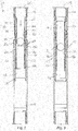
Figs. 2-6 illustrate cross-sectional views of an indexing sleeve of the present disclosure in different operational states. -
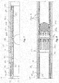
Fig. 7 illustrates a detailed cross-section of a portion of the disclosed indexing sleeve. -
Fig. 8 illustrates a cross-sectional view of a portion of the disclosed indexing sleeve having an alternative indexer. -
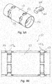
Figs. 9A-9B illustrate perspective and cross-sectional views of portion of another indexer for the disclosed indexing sleeve. -
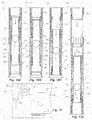
Figs. 10A-10D illustrate cross-sectional views of the disclosed indexing sleeve having yet another indexer. -
Fig. 11 diagrams details of the indexer ofFigs. 10A-10D . -
Figs. 12A-12C illustrate cross-sectional views of portions of the disclosed indexing sleeve with different electronic index devices. -
Fig. 13 schematically illustrates components of an electronic index device. -
Fig. 14 illustrates an alternative downhole tool having an indexer as disclosed herein. - A
tubing string 12 for a wellborefluid treatment system 20 shown inFig. 1 deploys in a wellbore 10 from arig 20 having apumping system 35. Thestring 12 has flow tools orindexing sleeves 100A-C disposed along its length.Various packers 40 isolate portions of thewellbore 10 into isolated zones. In general, thewellbore 10 can be an opened or cased hole, and thepackers 40 can be any suitable type of packer intended to isolate portions of the wellbore into isolated zones. - The
indexing sleeves 100A-C deploy on thetubing string 12 between thepackers 40 and can be used to divert treatment fluid selectively to the isolated zones of the surrounding formation. Thetubing string 12 can be part of a fracture assembly, for example, having a top liner packer (not shown), a wellbore isolation valve (not shown), and other packers and sleeves (not shown) in addition to those shown. If thewellbore 10 has casing, then thewellbore 10 can havecasing perforations 14 at various points. - As conventionally done, operators deploy a setting ball to close the wellbore isolation valve (not shown). Then, operators rig up
fracing surface equipment 35 and pump fluid down the wellbore to open a pressure-actuated sleeve (not shown) toward the end of thetubing string 12. This treats a first zone of the formation. Then, in a later stage of the operation, operators selectively actuate theindexing sleeves 100A-C between thepackers 40 to treat the isolated zones depicted inFig. 1 . - The
indexing sleeves 100A-C have activatable indexers (not shown) according to the present disclosure. Internal components of a givenindexing sleeve 100A-C count passage of the dropped plugs or other objects. Once the givenindexing sleeve 100A-C has passed a set number of plugs, an internal plugless valve (not shown) in theindexing sleeve 100A-C closes and allows applied fluid pressure to open the givensleeve 100A-C. In this way, one sized plug can be dropped down thetubing string 12 to activate the plugless valve on theindexing sleeve 100A-C so it can be selectively opened. - Although indexing
sleeves 100A-C are shown, it will be understood that thesystem 10 can include other types of sliding sleeves, such as those actuated by engaging a plug with a seat so applied pressure can open the sliding sleeve. In fact, various combinations of conventional sliding sleeves and indexingsleeves 100 can be combined together in a system and can use different sized plugs (i.e., balls) to coordinate different stages of opening the sleeves. In this sense, certain deployed plugs of a smaller size may be allowed to pass through a given one of theindexing sleeve 100 without the passage being counted so that the deployed plug can perform another purpose in the system, such as seating in a conventional sliding sleeve or being counted when passing through anotherindexing sleeve 100 configured to count the particular deployed plug's passage. It will be appreciated with the benefit of the present disclosure that a number of useful arrangements ofdifferent indexing sleeves 100, different deployed plugs, and other downhole tools can be used in a system according to the present disclosure. - With a general understanding of how the indexing
sleeves 100 are used, attention now turns to details of indexingsleeves 100 according to the present disclosure. - One embodiment of an
indexing sleeve 100 is illustrated during different stages of operation inFigures 2-6 . Theindexing sleeve 100 has ahousing 102 defining ahousing bore 104 therethrough. One or moreexternal ports 106 on thehousing 102 communicate thebore 104 outside thesleeve 100. Ends (not shown) of thehousing 102 couple to a tubing string (not shown) in a conventional manner. - Inside, the
housing 102 has a main sleeve or insert 110 disposed in itsbore 104. Themain insert 110, which defines itsown bore 112, can move axially from a closed condition (Figs. 2-5 ) covering theports 106 to an open condition (Fig. 6 ) exposing theports 106. Themain insert 110 can be moved after an appropriate number of plugs (e.g., balls B or other) has passed through theindexing sleeve 100 and applied pressure in thehousing 102 moves theinsert 110, as discussed in more detail below. - A
valve 120 is connected to themain insert 110 and is movable from an opened condition (Figs. 2-5 ) unobstructing the housing bore 104 (and insert's bore 112) to a closed condition (Fig. 6 ) obstructing the bore(s) 104, 112. Thevalve 120 is plugless in the sense that thevalve 120 does not use a deployed plug to seal off fluid flow, as is conventionally done with a typical plug and seat arrangement of the prior art. Instead, the disclosedvalve 120 is independent of the deployed plugs and closes to obstruct or block thebores - An
indexer 130 is disposed relative to themain insert 110. As will be discussed below, theindexer 130 counts passage of plugs through the bore(s) 104, 112 and permits movement of thevalve 120 from the opened condition (Figs. 2-5 ) to the closed condition (Fig. 6 ) in response to the counted number. - As shown, the
indexer 130 includes a second insert or flowtube 131 defining abore 132. Thissecond insert 131 is disposed in thebore 112 of themain insert 110 and can move axially in thebore 112 from a first condition (Figs. 2-3 ) against thevalve 120 in the opened condition to a second condition (Figs. 4-6 ) away from thevalve 120. As shown inFigures 5-6 , thesecond insert 130 in the second condition permits movement of thevalve 120 from the opened condition to the closed condition to obstruct thebores - In fact, the
second insert 131 is a sleeve having a flow tube at its upper end that covers thevalve 120, which is a flapper valve pivotably connected by ahinge 122 to acage 124 on the upper end of themain insert 110. When thesecond insert 131 is moved axially downward inside themain insert 110, the flow tube at the upper end of theinsert 131 exposes theflapper valve 120 to the main insert'sbore 112, allowing theflapper valve 120 to pivot across thebore 112 and obstruct flow. Thehinge 122 can include a spring or the like to bias theflapper valve 120 to its closed condition (Fig. 6 ). - Instead of a flow tube at its end, for example, the
insert 131 can have a rod, an arm, a linkage, or the like to move away from theflapper valve 120 and allow it to close or to actively grab and close theflapper valve 120. - In operation of the
indexing sleeve 100, the indexer'sinsert 131 indexes as it translates through themain insert 110, which carries theflapper valve 120. Initially, theflapper valve 120 is inaccessible to the flow until the arranged index of the indexer'sinsert 131 has moved out of the way of theflapper valve 120, which can then close. Once closed, theflapper valve 120 acts as an obstruction in thebore insert 131 out of the way. - As can be seen, the plug or ball B is used for indexing the
sleeve 100, but the ball B is not seated and used as a plug for opening of thesleeve 100. Instead, the indexing by the ball is disconnected from the plugging of thesleeve 100. Rather, theflapper valve 120 on themain insert 110 acts as the plug mechanism and does not require any external member to create interference in the passage of the fluid. - As noted above, the
indexer 130 counts passage of plugs through the bore(s) 104, 112 and permits pivoting of theflapper valve 120 in response to the counted number. To do this, theindexer 130 has keys ordogs 134 disposed in thebore 132 of thesecond insert 131. Thedogs 134 are alternatingly engageable and disengagable with the passage of plugs B in thesecond bore 132 and are correspondingly disengageable and engageable withslots 114 defined in thefirst bore 112 of themain insert 110. - For further reference,
Figure 7 shows some particular details of these features. As shown, thedogs 134 specifically include first,upper dogs 134a disposed about thesecond bore 132 and axially displaced from second, lower dogs 134b also disposed about the second bore. A passing ball B initially engages theupper dogs 134a, which are disposed in betweenslots 114 and extend into thebore 132. Pressure applied behind the engaged ball B moves thesecond insert 131 axially in themain insert 110 against the bias of aspring 138. Advancing one indexed step, theupper dogs 134a reach arespective slot 114 and retract from thebore 132 and the pushed ball B, while the lower dogs 134b leave arespective slot 114 and extend into thebore 132 to engage the ball B. - Again, pressure applied behind the engaged ball B moves the
second insert 131 axially in themain insert 110 against the bias of aspring 138. Advancing another indexed step, the lower dogs 134b reach arespective slot 114 and retract from thebore 132 to release the ball B to pass further downhole. The upper dogs 134b leave arespective slot 114 and extend into thebore 132 to engage any subsequently passed ball B. - To maintain the indexed advancement of the
second insert 131, theindexer 130 has a set of locks 136a-c disposed on thesecond insert 131. As theinsert 131 advances, the locks 136a-c alternatingly engage with theslots 114 in thefirst bore 112 of themain insert 110. These locks 136a-c can be snap rings or the like with ramped lead edges to advance out of theslots 114. At least one of the locks (e.g., 136c) has a shoulder on a trailing edge to lock against a respective shoulder of theslots 114 and prevent the bias of thespring 138 from moving thesecond insert 131 axially back. A body lock ring (not shown) or other ratcheting mechanism could alternatively be used in place of the locks 136a-c. - Turning now to the activation of the
sleeve 100,Figure 2 shows thesleeve 100 in a closed state having themain insert 110 closed relative to theports 106. Fluid communicated down the tubing string (not shown) can pass further downhole to other parts of a fracture system, such as other sleeves or the like. During the course of operations, an initial ball B1 is dropped, deployed, pumped, etc. down the tubing string (not shown) to actuate a part of the fracture system. This initial ball B1 reaches the givensleeve 100 as shown inFigure 2 and engages theupper dogs 134a extended into thebore 132 of theindexer 130. Applied pressure behind the ball B1 advances the indexer'sinsert 131 in the main insert'sbore 112. - With the advancement as shown in
Figure 3 , theupper dogs 134a retract from thebore 132, while the lower dogs 134b extend into thebore 132 to engage the initial ball B1. Again, applied pressure behind the ball B1 advances the indexer'sinsert 131 in the main insert'sbore 112. With the advancement, thelower dogs 134a retract from thebore 132 and allow the initial ball B1 to pass on to other downhole parts of the fracture system. Meanwhile, the upper dogs 134b extend back into thebore 132 to engage a subsequent ball (not shown). The locks 136a-c on theindexer 130 prevent reverse movement of the indexer'sinsert 131 so that the flow tube at the end of theinsert 131 has moved one indexed movement away from theflapper valve 120. - This process of moving the
indexer 130 can then be repeated one or more times by engaging one or more subsequent balls (not shown). The number of balls counted by theindexer 130 depends on the number ofslots 114 in thehousing 110 and what initial position theindexer 130 had at the start. These can be configured for a particular count depending on the location of thesleeve 100 in the fracture system and the number of balls B it needs to count in the overall scheme of the fracture operations. - Eventually as shown in
Figure 4 , a final ball BN reaches theindexer 130 and advances thesecond insert 131 enough to expose theflapper valve 120 to theinternal bore 104 of thesleeve 100. At this point, a number of actions are possible to both release and close theflapper valve 120, move thesecond insert 131 its final movement, and release the ball BN. - As shown in
Figure 5 , the final movement of thesecond insert 131 can move thedogs 134a-b out of anyslots 114 so that thedogs 134a-b extend into the insert'sbore 132 and at least temporarily hold the ball BN. This can allow pressure behind the engaged ball B to move thesecond insert 131 its final movement so that a lock 138 (e.g., snap ring) disposed on thesecond insert 131 can engage in agroove 118 in the main insert'sbore 112. As then shown inFigure 6 , the final ball BN can be released from thedogs 134a-b after being temporarily held. The temporary holding of the ball BN may not be strictly necessary if the final movement of thesecond insert 131 for closing theflapper valve 120 can be achieved without the ball BN being held. - With the
insert 131 moved as shown inFigure 6 , theflapper valve 120 can then close off fluid flow further downhole by obstructing thevarious bores flapper valve 120 can be achieved primarily by the flow of fluid and applied pressure. A coil spring or the like at thehinge 122 may also assist in pivoting theflapper valve 120. To prevent premature closing of theflapper valve 120, a retainer (not shown) can be used to hold theflapper valve 120 open at least until a necessary flow level, pressure level, movement, or the like is achieved. - With the
flapper valve 120 pivoted closed as shown inFigure 6 , the applied pressure forced against the obstructingflapper valve 120 can move themain insert 110 in the housing'sbore 104 and eventually expose theports 106. Notably, the engagement of theflapper valve 120 with the seat area does not need to be a purely fluid tight seal, although it could. Overall, the closing of theflapper valve 120 is intended to create a flow barrier so pressure applied behind theflapper valve 120 can be used to open themain insert 110. - With the
main insert 110 moved axially to its open position as shown inFigure 6 , a lock (e.g., snap ring 118a) disposed on themain insert 110 can engage in agroove 108 of the housing'sbore 104. At this point, themain insert 110 can be held in its open position. - Various faces could be used on the
flapper valve 120 depending on the amount of space available. To conserve space and conceal theflapper valve 120 effectively in thehousing 102 that is cylindrical, theflapper valve 120 may be curved to fit in the annulus between theflow tube 131 at the end of theinsert 130 and the housing'sbore 104. Such a conventional curved shape found on downhole, curved flappers can allow theflapper valve 120 of the disclosedsleeve 100 to fit in an annular space between the flow tube of thesecond insert 131 and thebore 104 of thehousing 102. Additionally, theseating area 126 for theflapper valve 120 can have a corresponding shape suited for the curved flapper. - In one configuration, the
second insert 131 locks in its final position away from theflapper valve 120 and does not move back to its initial position. Use of the snap rings 136a-c for the locks on thesecond insert 131 can lock theinsert 131 in its final position. - Should the lock used between the
second insert 131 and the main insert'sbore 112 allow for final release, then thesecond insert 131 can be released and allowed to move to its initial position with the flow tube closing and covering theflapper valve 120 in thecage 124 once fluid pressure against theclosed flapper valve 120 recedes. This may allow the flow passage through thesleeve 100 to be reopened after the fracturing of the respective zone. The lock (not shown) used to achieve this may include a body lock ring or other ratcheting mechanism that is sheared free and released once thesecond insert 131 reaches its final position in the insert'sbore 112. - After the multistage fracturing operations are complete, operators may or may not mill out components of the
sleeve 100. For instance, theindexing sleeve 100 can still operate with theflapper valve 120 remaining and still allow production flow uphole. Pressure can equalize across theflapper valve 120, allowing it to open during production. Alternatively, operators may mill out internal components of thesleeves 100 to provide a larger internal dimension for production. This is typically done using a milling tool to mill components that restrict the bore through the tubing string. - Accordingly, milling can be used with the disclosed
sleeve 100 to remove restrictions. For example, milling can remove components of theflapper valve 120 and theindexer 130. Themain insert 110 can remain in thehousing 102 after milling and may engage with anti-rotation components inside thehousing 102. Milling can also mill out theflapper valve 120, thecage 124, thesecond insert 131,dogs 134,spring 138, etc. - Various materials can be used for these components to achieve both sealed operation during fracture treatment and subsequent milling. For example, certain components can be composed of cast iron, aluminum, composite, phenolic, or other millable material. Certain components may be composed of a dissolvable material intended to degrade or dissolve over time with downhole exposure. Various options for materials, milling procedures, and the like are available and used with the conventional ball and seat arrangements on sliding sleeves, and the disclosed
indexing sleeves 100 can benefit from similar options. - Finally, regardless of whether milling is performed or not, operators may or may not close the
various inserts 110 on thesleeves 100 after their use. Closing theinserts 110 can be achieved in a number of ways, including using a shifting tool on appropriate profiles (not shown) on the insert, using coiled tubing to engage theinsert 110 and mechanically shift it in thehousing 102, etc. - In previous implementations, the
indexer 130 usesdogs 134a-b for alternatingly engaging and disengaging in slots in thebore 112 of themain insert 110 to alternatingly retract and extend in the second insert'sbore 132. Other configurations can be used for indexing. For example,Figure 8 shows anindexer 140 for the disclosedsleeve 100. Features of thisindexer 140 can be similar to features disclosed inU.S. Pat. No. 8,701,776 . - The
indexer 140 is similar in many respects to that disclosed previously with reference toFigures 2-6 . Again, theindexer 140 includes a second insert or flow tube 141, which is axially movable in thebore 112 of themain insert 110 away from the flapper (120). Rather than using dogs as before, theindexer 140 has upper andlower collets 142a-b-each having a plurality of keys orfingers 144a-b. Thefingers 144a-b are alternatingly engageable and disengagable with the passage of plugs B in thesecond bore 142 and are correspondingly disengageable and engageable withslots 114 defined in thefirst bore 112 of themain insert 110. Theindexer 140 also has a similar configuration oflocks 146a-b. - In another example,
Figures 9A-9B shows portion of anotherindexer 150 for the disclosedsleeve 100. Features of thisindexer 150 can be similar to other features also disclosed inU.S. Pat. No. 8,701,776 . Theindexer 150 is similar in many respects to that disclosed previously with reference toFigures 2-6 and includes a second insert 151. Again, this second insert 151 is axially movable in the bore (112) of the main insert (110) away from the flapper (120). - This
indexer 150 uses a dog assembly having two sets of keys ordogs 154a-b rather than the fingers of collets. Each set ofdogs 154a-b are equally spaced around the tubular body of the insert 151. As before, thedogs 154a-b are engageable with slots (114) of the insert's bore (112). Eachdog 154a-b is disposed in awindow 153 of the insert 151, and eachdog 154a-b is movable between a retracted position flush with the insert'sbore 152 and an extended position protruding into thebore 152.Figure 9B shows both positions. Eachdog 154a-b can havewings 155 to prevent thedog 154a-b from escaping thewindows 153. - Other mechanical indexing mechanism can be used. For example, a J-slot indexing mechanism can be used to count passage of deployed plugs or balls B to then close the
flapper valve 120 so the sleeve'sinsert 110 can be opened with applied pressure. Looking atFigures 10A-10D , cross-sectional views show the disclosedindexing sleeve 100 having yet anotherindexer 130 based on a J-slot mechanism. Theindexing sleeve 100 has many of the same components as before so that like reference numbers are used for similar components. - In some differences, the
inner bore 112 of themain insert 110 defines a different arrangement of slots. In particular,Figure 11 diagrams a portion of the inside surface of the main insert'sinner bore 112. For instance, portion (e.g., one quarter or one half) of the circumference of the main insert'sinner bore 112 is shown inFigure 11 as if rolled out flat to reveal the arrangement of slots. This same pattern can repeated symmetrically on the remaining portion of the bore's surface, which is not shown. - As shown in
Figure 11 , a J-slot 113 is defined on portion of the bore's surface for indexing movement of the indexer (130). As diagramed, apin 133 that is disposed on the exterior of the indexer (130) can ride in this J-slot 113 between a number of junctions (a through j). The bore's surface also defines afirst retraction slot 115 about portion of its circumference for retraction of the indexer's keys or dogs 134-one of which is shown isolated for illustrative purposes. - A
second retraction slot 117 is axially displaced from thefirst retraction slot 115 and encompasses another portion of the bore's circumference. Thissecond retraction slot 117 is also used to retract the indexer's key 134 after the indexer (130) makes its final index of junction (h) to (i), as discussed below. Finally, aretention slot 119 is defined on the bore's surface for locking the indexer (130), as discussed below. - With an understanding of the
various slots pins 133; andkeys 134; discussion turns to how these components can be used to index passage of balls through thesleeve 100. As shown inFigure 10A , an initial ball B1 deployed to thesleeve 100 engages theextended keys 134 on theindexer 130. Applied pressure behind the seated ball B1 pushes the indexer'sinsert 131 down against the bias of thespring 135. - As shown in
Figure 10B , the indexer'sinsert 131 moves axially down an amount, and thekeys 134 reach thefirst retraction slot 115 allowing for release of the ball B1. As can be seen inFigure 11 , this first movement axially down translates to movement of thepin 133 to junction (a) in the J-slot 113 and to a slight turn of the indexer'sinsert 131 in the main insert'sbore 112. With the ball B1 released as shown inFigure 10B , the biasingelement 135 can then push the indexer'sinsert 131 upward to its starting position so that the indexer'skeys 134 extend outward again in the manner ofFigure 10A to engage the next ball. As can be seen inFigure 11 , this reverse movement axially upward translates to movement of thepin 133 to junction (b) in the J-slot 113 and to a slight turn of the indexer'sinsert 131 in the main insert'sbore 112. This amounts to a count of one passage of the ball B1. - The above indexing process can be repeated as many times as desired, depending on the number of provided junctions. Eventually as shown in
Figure 10C , a final ball Bi is deployed and engages theextended keys 134, when-as shown inFig. 11 -thepin 133 resides in junction (h). Applied pressure behind the seated ball Bi pushes the indexer'sinsert 131 down against the bias of thespring 135. - Because the indexer's
insert 131 has made turns relative to themain insert 110, thekeys 134 remain extended as they travel axially along the surface of thebore 112 in the space between the first andsecond retraction slots keys 134 reach thesecond retraction slot 117 allowing for release of the final ball Bi. - As can be seen in
Figure 11 , this final movement axially down translates to movement of thepin 133 to junction (i) in the J-slot 113 and to a slight turn of the indexer'sinsert 131 in the main insert'sbore 112. With the final ball Bi released, the biasingelement 135 then pushes the indexer'sinsert 131 axially upward, which translates to movement of thepin 133 to the last junction (j) in the J-slot 113. - At the same time of this final movement toward junction (i), the
lock ring 138 on theindexer 130 engages at theretention slot 119, as shown inFigure 10C . This can hold theindexer 130 in its axially downward position in themain insert 110, which allows theflapper valve 120 to pivot down. As eventually shown inFigure 10D , applied pressure against theclosed flapper valve 120 can then be used to push themain insert 110 open relative to the housing'sexit ports 106. - Although mechanical indexing in response to passage of deployed plugs or balls B may be preferred in some implementations and has been described above, the disclosed tool, such as the sliding
sleeve 100, can also use electronic indexing and can respond to passage of deployed plugs, balls, or even other objects, such as tags, markers, and the like. - In one particular example,
Figure 12A shows the disclosedsleeve 100 having ahousing 102, amain insert 110, aflapper valve 120, and anindexer 130. Rather than mechanically indexing with the passage of a ball B through thesleeve 100, an electro-mechanical index device 160 counts the passage of the balls B. Then, when a set number of balls B pass, theindex device 160 moves theindexer 130 so that theflow tube 131 exposes theflapper valve 120, allowing it to close. - A number of electro-
mechanical index devices 160 can be used to mechanically engage the passage of the ball, electronically count that passage, and then electronically trigger the mechanical movement of theindexer 130. In this example, thedevice 160 include abiased button 162 disposed in thebore 132 of theindexer 130.Electronics 164 count when a passing ball B engages and moves thebutton 162. When a set number of passages occur, theelectronics 164 then activate the movement of theindexer 130. - For instance, the
electronics 164 can couple to afuse 165 for abreakable retainer 166. When thefuse 165 is triggered, it breaks theretainer 166, allowing for movement of theindexer 130. In one arrangement, anextended biasing element 168 can then pull theindexer 130, moving theflow tube 131 so theunconcealed flapper valve 120 can close. - In another example of
Figure 12B , theindex device 160 includes anelectronic sensor 163 that senses the passage of plugs, balls, or other objects (e.g., RFID tags, magnetic elements, etc.) through thesleeve 100. Theelectronics 164 count when a passing object passes thesensor 163, and when a set number of passages occur, theelectronics 164 then activate the movement of theindexer 130. For instance, theelectronics 164 can trigger thefuse 165 to break theretainer 166 so theextended biasing element 168 can move theindexer 130. - In yet another example of
Figure 12C , theindex device 160 includes anelectronic sensor 163 that senses the passage of the plugs, balls, or objects through thesleeve 100.Electronics 164 count when a passing ball or other object passes thesensor 163, and when a set number of passages occur, theelectronics 164 then activate the movement of theindexer 130. For instance, theelectronics 164 can include asolenoid 170 that opens passage of aninternal port 172 so tubing pressure can enter achamber 174 and move theindexer 130 to reveal theflapper valve 120. An opposingvacuum chamber 161 may facilitate the movement. - Some possible components of the
index device 160 are schematically illustrated inFigure 13 . Theelectronics 164 include acontroller 180, which can include any suitable processor for a downhole tool. Thecontroller 180 is operatively coupled to the sensor orreader 163 and to anactuator 190. - The type of sensor or
reader 163 used depends on how commands are conveyed to theindex device 160 while deployed downhole. Various types of sensors orreaders 163 can be used, including, but not limited to, a radio frequency identification (RFID) reader, sensor, or antenna; a Hall Effect sensor; an electronic button; and the like. For example, to detect passage of the balls B, thesensor 163 can be activated with any number of techniques-e.g., RFID tags or magnetic elements T can be disposed in the balls B or physical passage of the balls B other their own can activate thesensor 163. In other examples, thesensor 163 does not require the passage of a ball B or other such plug and instead may merely sense passage of objects or other triggers T, such as RFID tags, magnetic elements, and the like, passing in the flow stream. Any other form of sensing could also be used as triggers, such as chemical tracers used in the flow stream; mud pressure pulses (if the system is closed chamber); mud pulses (if the system is actively flowing); etc. - For instance, the
sensor 163 can be an RFID reader that uses radio waves to receive information (e.g., data and commands) from one or more electronic RFID tags T, which can pass alone in the flow or can be attached to a ball B, plug, or the like. The information is stored electronically, and the RFID tags T can be read at a distance from thereader 163. To convey the information to theapparatus 100 at a given time during operations, the RFID tags T are inserted into the tubing (20) at surface level and are carried downhole in the fluid stream. When the tags T come into proximity to theapparatus 100, the electronic reader 202 on the tool'selectronics 164 interprets instructions embedded in the tags T to perform a required operation. - Logic of the
controller 180 can count triggers, such as the passage of a particular RFID tag T, a number of RFID tags T, or the like. In addition and as an alternative, the logic of thecontroller 180 can use timers to actuate theactuators 190 after a period of time has passed since a detected trigger (e.g., after passage of an RFID tag T or after a previous operation is completed). These and other logical controls can be used by thecontroller 180. - When a particular instruction is detected, for example, the
controller 180 operates aswitch 182 or the like, to supply power from apower source 184 to one or more of theactuators 190, which can include one or more motors, pumps, solenoids, fuses, or other devices to provide force, pressure, counter bias, or the like to the indexer'sinsert 130 of the sleeve (100). Thepower source 184 can be a battery that is deployed downhole with theelectronics 164. Theactuators 190 in the form of motors can be operatively coupled to the indexer'sinsert 130 of thesleeve 100 with gears and the like. When activated, themotor actuators 190 can move the indexer'sinsert 130 as disclosed herein. - The
actuators 190 in the form of pump(s) or solenoid(s) can be operatively coupled between pressure source(s) or reservoir(s) as thepower source 184 and the indexer'sinsert 130. For example, the pressure source orreservoir 184 can be a reservoir of high pressure fluid. Thesolenoid actuators 190 can be activated by the power to open and allow the high pressure fluid to act on the indexer'sinsert 130. Alternatively, the pressure source(s) or reservoir(s) 184 may be a reservoir of hydraulic fluid. The pump actuators 190 can be activated by the power to pump the hydraulic fluid of thesource 184 to apply pressure against the indexer'sinsert 130. Additionally, thepump actuators 190 can be operated in the reverse to relieve pressure against theinsert 130. - Although the disclosed tool has been described as a sliding sleeve, such as a fracturing sleeve for a tubing string, the teachings of the present disclosure can be used for other downhole tools, such as flow valves, sliding sleeves, safety valves, and the like.
- As one example,
Figure 14 shows portion of a downhole tool as a tubing valve. Thetubing valve 200 has a housing 202 defining ahousing bore 204 therethrough. Ends (not shown) of the housing 202 couple to a tubing string (not shown) in a conventional manner. - Inside the housing 202, a
flapper valve 220 is movable from an opened condition unobstructing the housing bore 202 to a closed condition obstructing the bore 202. Anindexer 230 is disposed in the housing's bore 202. Theindexer 230 counts passage of plugs or other object through the bore 202 and permits movement of theflapper valve 220 from the opened condition to the closed condition in response to the counted number. - As shown, the
indexer 230 includes an insert or flowtube 231 defining a bore 232. Thisinsert 231 is disposed in thebore 204 of the housing 202 and can move axially in thebore 204 from a first condition against theflapper valve 220 in the opened condition to a second condition away from theflapper valve 220. Theinsert 230 in the second condition permits movement of theflapper valve 220 from the opened condition to the closed condition. - In fact, the
insert 231 is a sleeve having a flow tube at its upper end that covers theflapper valve 220 pivotably connected by ahinge 222 to a cage 224 inside thebore 204. When theinsert 231 is moved axially downward inside thebore 204, the flow tube at the upper end of theinsert 231 exposes theflapper valve 220 to thebore 204, allowing theflapper valve 220 to pivot across thebore 204 and obstruct flow. Thehinge 222 can include a spring or the like to bias theflapper valve 220 to its closed condition. - In operation of the
tubing valve 200, the indexer'sinsert 231 indexes as it translates through the housing'sbore 204. Initially, theflapper valve 220 is inaccessible to the flow until the arranged index of the indexer'sinsert 231 has moved out of the way for theflapper valve 220 to close. - The
indexer 230 counts passage of plugs through the bore 202 and permits pivoting of theflapper valve 220 in response to the counted number. To do this, theindexer 230 hasdogs 234 disposed in the bore 232 of thesecond insert 231. Thedogs 234 are alternatingly engageable and disengagable with the passage of plugs B in the bore 232 and are correspondingly disengageable and engageable withslots 214 defined in thehousing bore 204. (Any of the other indexers-either electronic or mechanical-disclosed above could be used instead.) Once theflapper valve 220 is exposed in thebore 204, theflapper valve 220 in the current arrangement pivots upward to prevent downhole pressure from passing further uphole. The opposite configuration is also possible as disclosed herein. - The foregoing description of preferred and other embodiments is not intended to limit or restrict the scope or applicability of the inventive concepts conceived of by the Applicants. It will be appreciated with the benefit of the present disclosure that features described above in accordance with any embodiment or aspect of the disclosed subject matter can be utilized, either alone or in combination, with any other described feature, in any other embodiment or aspect of the disclosed subject matter.
- Although the
flapper valve 120 is shown pivotably mounted on acage 124 that connects to themain insert 110, this may be done to facilitate assembly. An integrated construction between theflapper valve 120 andmain insert 110 could be used. - Although the
second insert 131 of theindexer 130 has a flow tube at its distal end to move away from theflapper valve 120 and allow it to open, other configurations are possible. Rather than a flow tube, for example, theindexer 130 can use any suitable latch, linkage, arm, etc. between theindexer 130 and theflapper valve 120 to achieve the same results in substantially the same way. - Although reference to balls have been made repeatedly herein as a form of plug to be deployed downhole, other types of plugs, balls, darts, and other objects can be used, as will be appreciated by one skilled in the art.
- In exchange for disclosing the inventive concepts contained herein, the Applicants desire all patent rights afforded by the appended claims.
Claims (22)
- A downhole tool (100) responsive to passage of one or more objects (B) and applied fluid pressure, the tool (100) comprising:a housing (102) defining a housing bore (104) therethrough and defining at least one port (106) communicating the housing bore (104) outside the housing (102);a plugless valve (120) disposed in the housing (102) and operable from an unobstructed condition unobstructing the housing bore (104) to an obstructed condition obstructing the housing bore (104) to the applied fluid pressure,wherein the plugless valve (120) comprises a first insert (110) and a valve element, the first insert (110) disposed in the housing bore (104) and defining a bore (112) therethrough, the valve element disposed relative to the first insert (110) and movable from an unobstructed condition unobstructing the bore (112) to an obstructed condition obstructing the bore (112) to the applied fluid pressure,the valve element in the obstructed condition permitting axial movement of the first insert (110) in the housing bore (104) from a closed condition covering the at least one port (106) to an opened condition exposing the at least one port (106); andan indexer (130) disposed relative to the plugless valve (120), the indexer (130) configured to count the passage of a number of the one or more objects (B) through the housing bore (104) and to permit operation of the valve element and the plugless valve (120) from the unobstructed condition to the obstructed condition in response to the counted number,wherein, in response to the applied fluid pressure against the valve element in the obstructed condition, the first insert (110) is axially movable in the housing bore (104) from the closed condition to the opened condition, andwherein the tool (100) is configured such that applied fluid pressure in the housing bore (104) obstructed by the valve element of the plugless valve (120) in the obstructed condition communicates from the housing bore (104) outside the housing (102) via the at least one port (106).
- The tool (100) of claim 1, wherein the indexer (130) comprises a second insert (131) disposed in the bore (112) of the first insert (110) and axially movable in the bore (112) from a first condition toward the valve element (120) in the unobstructed condition to a second condition away from the valve element (120), the second insert (131) in the second condition permitting the movement of the valve element (120) from the unobstructed condition to the obstructed condition.
- The tool (100) of claim 2, wherein the indexer (130) comprises at least one key (134) disposed in a bore (132) of the second insert (131), the at least one key (134) alternatingly engageable and disengagable with the passage of each object (B) in the bore (132) and correspondingly disengageable and engageable with at least one slot (114) in the bore (112) of the first insert (110).
- The tool (100) of claim 3, wherein the at least one key (134) comprises first and second dogs (134a, 134b) disposed about the bore (132) of the second insert (131), the first dogs (134a) axially displaced from the second dogs (134b).
- The tool (100) of claim 3 or 4, wherein the indexer (130) comprises at least one lock (136a;136b;136c) disposed on the second insert (131) and alternatingly locking with the at least one slot (114) in the bore (112) of the first insert (110).
- The tool (100) of claim 5, wherein at least one of:the at least one lock (136a;136b;136c) comprises snap rings disposed about the second insert (131), at least one of the snap rings having a shoulder along a first edge for engaging in the at least one slot (114) and having a ramp along a second edge for passing out of the at least one slot (114); and/orthe indexer (130) comprises a biasing member (138) configured to bias the second insert (131) axially in the first bore of the first insert (110) toward the first condition.
- The tool (100) of any one of claims 3 to 6, wherein one of:the second insert (131) comprises a pin (139), and wherein the bore (112) of the first insert (110) defines a J-slot (113) in which the pin (139) is disposed, the J-slot (113) defining a plurality of junctions (a - i) for counting the passage of the one or more objects (B);the second insert (131) comprises a pin (139), and wherein the bore (112) of the first insert (110) defines a J-slot in which the pin (139) is disposed, the J-slot (113) defining a plurality of junctions (a - i) for counting the passage of the one or more objects (B), and wherein the bore (112) of the first insert (110) defines a first retraction slot (115) permitting retraction of the at least one key (134) after first movement of the second insert (131) in the bore (112) of the first insert (110), and wherein the bore (112) of the first insert (110) defines a second retraction slot (117) permitting retraction of the at least one key (134) after second movement of the second insert (131) in the bore (112) of the first insert (110), the second movement being after the first movement and being longer in extent than the first movement;the second insert (131) comprises a pin (139), and wherein the bore (112) of the first insert (110) defines a J-slot (113) in which the pin (139) is disposed, the J-slot (113) defining a plurality of junctions (a - i) for counting the passage of the one or more objects (B), and wherein the bore (112) of the first insert (110) defines a first retraction slot (115) permitting retraction of the at least one key (134) after first movement of the second insert (131) in the bore (112) of the first insert (110), and wherein the bore (112) of the first insert (110) defines a second retraction slot (117) permitting retraction of the at least one key (134) after second movement of the second insert (131) in the bore (112) of the first insert (110), the second movement being after the first movement and being longer in extent than the first movement, and wherein the second insert (131) moved in the second movement places the second insert (131) in the second condition.
- The tool (100) of any of one claims 3 to 7, wherein the second insert (131) comprises one or more collets (142) having a plurality of fingers (144) with the at least one key (134).
- The tool (100) of any one of claims 2 to 8, wherein the second insert (131) comprises a lock (138) disposed on the second insert (131) and engageable against the first insert (110) when the second insert (131) is in the second condition.
- The tool (100) of any preceding claim, wherein the indexer (130) comprises an electronic sensor (163) configured to sense the passage of the one or more objects (B) past the electronic sensor (163).
- The tool (100) of claim 10, when dependent on claim 2, wherein the indexer (130) comprises an actuator (190) in operable communication with the electronic sensor (163), the actuator (190) disposed relative to the second insert (131) and configured to axially move the second insert (131) toward the second condition.
- The tool (100) of claim 11, wherein the actuator (190) is selected from the group consisting of a solenoid, a fuse, a heating coil, a cord, a spring, a motor, and a pump.
- The tool (100) of any one of claims 1 to 10, wherein the indexer (130) comprises an actuator (190) configured to actuate the valve element of the plugless valve (120) from the unobstructed condition to the obstructed condition.
- The tool (100) of any preceding claim, wherein the valve element comprises a flapper valve pivotably connected to the first insert (110) and pivotable from the unobstructed condition unobstructing the bore (112) of the first insert (110) to the obstructed condition obstructing the bore (112) of the first insert (110).
- The tool (100) of claim 14, further comprising a lock disposed on the first insert (110) and engageable in the housing bore (104) with the first insert (110) in the unobstructed condition, wherein the lock comprises a snap ring (118a) engaging in a groove (108) defined around the housing bore (104).
- A method of actuating a sliding sleeve (100) downhole on a tubing string, the method comprising:counting passage of one or more objects (B) through a bore (104) of the sliding sleeve (100);closing a valve element of a plugless valve (120) in the bore (104) of the sliding sleeve (100) in response to the counted passage; andmoving a first insert (110) of the plugless valve (120) in the bore (104) of the sliding sleeve (100) relative to at least one port (106) in the sliding sleeve (100) with the applied pressure against the closed valve element of the plugless valve (120) and opening the at least one port (106) in the sliding sleeve (100) with the applied pressure against the closed valve element by moving the first insert (110) associated with the closed valve element in the sliding sleeve (100) open relative to the at least one port (106).
- The method of claim 16, whereincounting the passage of the one or more objects (B) through the bore (104) comprises indexing the first insert (110) axially in the sliding sleeve (100) with each passage.
- The method of claim 17, wherein indexing the first insert (110) axially in the sliding sleeve (110) with each passage comprises alternatingly engaging and disengaging each passage and shifting the first insert (110) axially in response thereto.
- The method of any one of claims 16 to 18, further comprising preventing reverse axial movement on the first insert (110).
- The method of any one of claims 16 to 19, wherein closing the valve element in the bore (104) of the sliding sleeve (100) in response to the counted passage comprises moving the indexed first insert (110) away from the valve element.
- The method of any one of claims 16 to 20, wherein closing the valve element of the plugless valve (120) in the bore (104) of the sliding sleeve (100) in response to the counted passage comprises pivoting a flapper across the bore (104).
- The method of any one of claims 16 to 21, wherein counting the passage of the one or more objects (B) through the bore (104) comprises releasing each of the one or more objects (B).
Applications Claiming Priority (1)
| Application Number | Priority Date | Filing Date | Title |
|---|---|---|---|
| US201462077029P | 2014-11-07 | 2014-11-07 |
Publications (3)
| Publication Number | Publication Date |
|---|---|
| EP3018285A2 EP3018285A2 (en) | 2016-05-11 |
| EP3018285A3 EP3018285A3 (en) | 2017-01-04 |
| EP3018285B1 true EP3018285B1 (en) | 2018-12-26 |
Family
ID=54476872
Family Applications (1)
| Application Number | Title | Priority Date | Filing Date |
|---|---|---|---|
| EP15193544.2A Not-in-force EP3018285B1 (en) | 2014-11-07 | 2015-11-06 | Indexing stimulating sleeve and other downhole tools |
Country Status (5)
| Country | Link |
|---|---|
| US (1) | US10392899B2 (en) |
| EP (1) | EP3018285B1 (en) |
| AU (1) | AU2015252150B2 (en) |
| CA (1) | CA2911551C (en) |
| DK (1) | DK3018285T3 (en) |
Families Citing this family (14)
| Publication number | Priority date | Publication date | Assignee | Title |
|---|---|---|---|---|
| EP3093428B1 (en) * | 2015-05-04 | 2019-05-29 | Weatherford Technology Holdings, LLC | Dual sleeve stimulation tool |
| US10337288B2 (en) * | 2015-06-10 | 2019-07-02 | Weatherford Technology Holdings, Llc | Sliding sleeve having indexing mechanism and expandable sleeve |
| EP3153656A1 (en) * | 2015-10-06 | 2017-04-12 | Welltec A/S | Downhole flow device |
| GB2553834A (en) | 2016-09-16 | 2018-03-21 | Schoeller Bleckmann Oilfield Equipment Ag | Splitflow valve |
| US20180230773A1 (en) * | 2017-02-14 | 2018-08-16 | Baker Hughes Incorporated | Interventionless Second Closure Operable with a Tubular String Isolation Valve |
| GB2574989B (en) * | 2017-04-14 | 2020-07-01 | Turbo Drill Ind Inc | Downhole tool actuators and indexing mechanisms |
| CN106948805B (en) * | 2017-05-11 | 2023-05-02 | 中国石油化工股份有限公司 | Multifunctional pipe inspection construction device for oil-water well and construction method thereof |
| CN109296336B (en) * | 2018-09-20 | 2023-11-28 | 中国石油天然气股份有限公司 | Sliding sleeve type blocking device and method for speed pipe column |
| US10801304B2 (en) * | 2018-09-24 | 2020-10-13 | The Wellboss Company, Inc. | Systems and methods for multi-stage well stimulation |
| US11280162B2 (en) | 2018-12-28 | 2022-03-22 | Baker Hughes, A Ge Company, Llc | Power generation using pressure differential between a tubular and a borehole annulus |
| US11365602B2 (en) * | 2019-03-27 | 2022-06-21 | Jovan Vracar | Programmable plug system and method for controlling formation access in multistage hydraulic fracturing of oil and gas wells |
| US11118687B2 (en) | 2019-04-08 | 2021-09-14 | Baker Hughes Oilfield Operations Llc | Plug system |
| US11142999B2 (en) | 2019-04-30 | 2021-10-12 | Baker Hughes Oilfield Operations Llc | Downhole power generation using pressure differential |
| CN110500079B (en) * | 2019-09-19 | 2021-05-25 | 中国石油化工股份有限公司 | Multi-stratum acidizing water injection string |
Family Cites Families (23)
| Publication number | Priority date | Publication date | Assignee | Title |
|---|---|---|---|---|
| US6041857A (en) | 1997-02-14 | 2000-03-28 | Baker Hughes Incorporated | Motor drive actuator for downhole flow control devices |
| EP1064451B1 (en) * | 1998-03-14 | 2002-12-11 | CHURCHILL, Andrew Philip | Pressure actuated downhole tool |
| US6209663B1 (en) | 1998-05-18 | 2001-04-03 | David G. Hosie | Underbalanced drill string deployment valve method and apparatus |
| US6571876B2 (en) * | 2001-05-24 | 2003-06-03 | Halliburton Energy Services, Inc. | Fill up tool and mud saver for top drives |
| US7451809B2 (en) | 2002-10-11 | 2008-11-18 | Weatherford/Lamb, Inc. | Apparatus and methods for utilizing a downhole deployment valve |
| US7387165B2 (en) | 2004-12-14 | 2008-06-17 | Schlumberger Technology Corporation | System for completing multiple well intervals |
| GB0716049D0 (en) * | 2007-08-17 | 2007-09-26 | Welltools Ltd | Switchable circulating tool |
| US8245788B2 (en) | 2009-11-06 | 2012-08-21 | Weatherford/Lamb, Inc. | Cluster opening sleeves for wellbore treatment and method of use |
| GB2478995A (en) | 2010-03-26 | 2011-09-28 | Colin Smith | Sequential tool activation |
| GB2478998B (en) * | 2010-03-26 | 2015-11-18 | Petrowell Ltd | Mechanical counter |
| US8403068B2 (en) | 2010-04-02 | 2013-03-26 | Weatherford/Lamb, Inc. | Indexing sleeve for single-trip, multi-stage fracing |
| US8505639B2 (en) * | 2010-04-02 | 2013-08-13 | Weatherford/Lamb, Inc. | Indexing sleeve for single-trip, multi-stage fracing |
| US8789600B2 (en) * | 2010-08-24 | 2014-07-29 | Baker Hughes Incorporated | Fracing system and method |
| US8978750B2 (en) | 2010-09-20 | 2015-03-17 | Weatherford Technology Holdings, Llc | Signal operated isolation valve |
| WO2012037645A1 (en) | 2010-09-22 | 2012-03-29 | Packers Plus Energy Services Inc. | Wellbore frac tool with inflow control |
| US9562419B2 (en) * | 2010-10-06 | 2017-02-07 | Colorado School Of Mines | Downhole tools and methods for selectively accessing a tubular annulus of a wellbore |
| US9664015B2 (en) * | 2010-10-21 | 2017-05-30 | Peak Completion Technologies, Inc. | Fracturing system and method |
| EP2484862B1 (en) * | 2011-02-07 | 2018-04-11 | Weatherford Technology Holdings, LLC | Indexing sleeve for single-trip, multi-stage fracing |
| US9010442B2 (en) | 2011-08-29 | 2015-04-21 | Halliburton Energy Services, Inc. | Method of completing a multi-zone fracture stimulation treatment of a wellbore |
| US9353598B2 (en) | 2012-05-09 | 2016-05-31 | Utex Industries, Inc. | Seat assembly with counter for isolating fracture zones in a well |
| US9624756B2 (en) | 2012-12-13 | 2017-04-18 | Weatherford Technology Holdings, Llc | Sliding sleeve having contracting, dual segmented ball seat |
| US9410401B2 (en) | 2013-03-13 | 2016-08-09 | Completion Innovations, LLC | Method and apparatus for actuation of downhole sleeves and other devices |
| US9284817B2 (en) * | 2013-03-14 | 2016-03-15 | Halliburton Energy Services, Inc. | Dual magnetic sensor actuation assembly |
-
2015
- 2015-11-06 CA CA2911551A patent/CA2911551C/en not_active Expired - Fee Related
- 2015-11-06 DK DK15193544.2T patent/DK3018285T3/en active
- 2015-11-06 AU AU2015252150A patent/AU2015252150B2/en not_active Ceased
- 2015-11-06 US US14/934,338 patent/US10392899B2/en not_active Expired - Fee Related
- 2015-11-06 EP EP15193544.2A patent/EP3018285B1/en not_active Not-in-force
Non-Patent Citations (1)
| Title |
|---|
| None * |
Also Published As
| Publication number | Publication date |
|---|---|
| DK3018285T3 (en) | 2019-04-08 |
| EP3018285A3 (en) | 2017-01-04 |
| US20160130910A1 (en) | 2016-05-12 |
| US10392899B2 (en) | 2019-08-27 |
| AU2015252150A1 (en) | 2016-05-26 |
| CA2911551C (en) | 2020-03-24 |
| AU2015252150B2 (en) | 2017-04-06 |
| CA2911551A1 (en) | 2016-05-07 |
| EP3018285A2 (en) | 2016-05-11 |
Similar Documents
| Publication | Publication Date | Title |
|---|---|---|
| EP3018285B1 (en) | Indexing stimulating sleeve and other downhole tools | |
| EP2372080B1 (en) | Indexing Sleeve for Single-Trip, Multi-Stage Fracturing | |
| EP2484862B1 (en) | Indexing sleeve for single-trip, multi-stage fracing | |
| US9441457B2 (en) | Indexing sleeve for single-trip, multi-stage fracing | |
| US9932797B2 (en) | Plug retainer and method for wellbore fluid treatment | |
| EP2559845B1 (en) | High flow rate multi array stimulation system | |
| US8215411B2 (en) | Cluster opening sleeves for wellbore treatment and method of use | |
| AU2014402801B2 (en) | Multi-zone actuation system using wellbore projectiles and flapper valves | |
| US9546538B2 (en) | Multi-stage fracturing with smart frack sleeves while leaving a full flow bore | |
| CA2674223C (en) | Reliable sleeve activation for multi-zone frac operations using continuous rod and shifting tools | |
| EP3093428B1 (en) | Dual sleeve stimulation tool | |
| CA2904312C (en) | Sliding sleeve having retrievable ball seat | |
| WO2014082054A1 (en) | Stimulation and production completion system |
Legal Events
| Date | Code | Title | Description |
|---|---|---|---|
| PUAI | Public reference made under article 153(3) epc to a published international application that has entered the european phase |
Free format text: ORIGINAL CODE: 0009012 |
|
| 17P | Request for examination filed |
Effective date: 20151106 |
|
| AK | Designated contracting states |
Kind code of ref document: A2 Designated state(s): AL AT BE BG CH CY CZ DE DK EE ES FI FR GB GR HR HU IE IS IT LI LT LU LV MC MK MT NL NO PL PT RO RS SE SI SK SM TR |
|
| AX | Request for extension of the european patent |
Extension state: BA ME |
|
| RIC1 | Information provided on ipc code assigned before grant |
Ipc: E21B 23/00 20060101AFI20160804BHEP Ipc: E21B 34/14 20060101ALI20160804BHEP Ipc: E21B 43/14 20060101ALI20160804BHEP Ipc: E21B 43/26 20060101ALI20160804BHEP |
|
| PUAL | Search report despatched |
Free format text: ORIGINAL CODE: 0009013 |
|
| AK | Designated contracting states |
Kind code of ref document: A3 Designated state(s): AL AT BE BG CH CY CZ DE DK EE ES FI FR GB GR HR HU IE IS IT LI LT LU LV MC MK MT NL NO PL PT RO RS SE SI SK SM TR |
|
| AX | Request for extension of the european patent |
Extension state: BA ME |
|
| RIC1 | Information provided on ipc code assigned before grant |
Ipc: E21B 43/26 20060101ALI20161130BHEP Ipc: E21B 43/14 20060101ALI20161130BHEP Ipc: E21B 23/00 20060101AFI20161130BHEP Ipc: E21B 34/14 20060101ALI20161130BHEP |
|
| GRAP | Despatch of communication of intention to grant a patent |
Free format text: ORIGINAL CODE: EPIDOSNIGR1 |
|
| STAA | Information on the status of an ep patent application or granted ep patent |
Free format text: STATUS: GRANT OF PATENT IS INTENDED |
|
| INTG | Intention to grant announced |
Effective date: 20180531 |
|
| GRAJ | Information related to disapproval of communication of intention to grant by the applicant or resumption of examination proceedings by the epo deleted |
Free format text: ORIGINAL CODE: EPIDOSDIGR1 |
|
| STAA | Information on the status of an ep patent application or granted ep patent |
Free format text: STATUS: REQUEST FOR EXAMINATION WAS MADE |
|
| GRAR | Information related to intention to grant a patent recorded |
Free format text: ORIGINAL CODE: EPIDOSNIGR71 |
|
| GRAS | Grant fee paid |
Free format text: ORIGINAL CODE: EPIDOSNIGR3 |
|
| STAA | Information on the status of an ep patent application or granted ep patent |
Free format text: STATUS: GRANT OF PATENT IS INTENDED |
|
| INTC | Intention to grant announced (deleted) | ||
| GRAA | (expected) grant |
Free format text: ORIGINAL CODE: 0009210 |
|
| STAA | Information on the status of an ep patent application or granted ep patent |
Free format text: STATUS: THE PATENT HAS BEEN GRANTED |
|
| INTG | Intention to grant announced |
Effective date: 20181107 |
|
| AK | Designated contracting states |
Kind code of ref document: B1 Designated state(s): AL AT BE BG CH CY CZ DE DK EE ES FI FR GB GR HR HU IE IS IT LI LT LU LV MC MK MT NL NO PL PT RO RS SE SI SK SM TR |
|
| REG | Reference to a national code |
Ref country code: GB Ref legal event code: FG4D |
|
| REG | Reference to a national code |
Ref country code: CH Ref legal event code: EP |
|
| REG | Reference to a national code |
Ref country code: AT Ref legal event code: REF Ref document number: 1081671 Country of ref document: AT Kind code of ref document: T Effective date: 20190115 |
|
| REG | Reference to a national code |
Ref country code: DE Ref legal event code: R096 Ref document number: 602015022191 Country of ref document: DE |
|
| REG | Reference to a national code |
Ref country code: IE Ref legal event code: FG4D |
|
| REG | Reference to a national code |
Ref country code: DK Ref legal event code: T3 Effective date: 20190401 |
|
| PG25 | Lapsed in a contracting state [announced via postgrant information from national office to epo] |
Ref country code: LV Free format text: LAPSE BECAUSE OF FAILURE TO SUBMIT A TRANSLATION OF THE DESCRIPTION OR TO PAY THE FEE WITHIN THE PRESCRIBED TIME-LIMIT Effective date: 20181226 Ref country code: HR Free format text: LAPSE BECAUSE OF FAILURE TO SUBMIT A TRANSLATION OF THE DESCRIPTION OR TO PAY THE FEE WITHIN THE PRESCRIBED TIME-LIMIT Effective date: 20181226 Ref country code: FI Free format text: LAPSE BECAUSE OF FAILURE TO SUBMIT A TRANSLATION OF THE DESCRIPTION OR TO PAY THE FEE WITHIN THE PRESCRIBED TIME-LIMIT Effective date: 20181226 Ref country code: BG Free format text: LAPSE BECAUSE OF FAILURE TO SUBMIT A TRANSLATION OF THE DESCRIPTION OR TO PAY THE FEE WITHIN THE PRESCRIBED TIME-LIMIT Effective date: 20190326 Ref country code: LT Free format text: LAPSE BECAUSE OF FAILURE TO SUBMIT A TRANSLATION OF THE DESCRIPTION OR TO PAY THE FEE WITHIN THE PRESCRIBED TIME-LIMIT Effective date: 20181226 |
|
| REG | Reference to a national code |
Ref country code: NL Ref legal event code: FP |
|
| REG | Reference to a national code |
Ref country code: LT Ref legal event code: MG4D |
|
| PG25 | Lapsed in a contracting state [announced via postgrant information from national office to epo] |
Ref country code: GR Free format text: LAPSE BECAUSE OF FAILURE TO SUBMIT A TRANSLATION OF THE DESCRIPTION OR TO PAY THE FEE WITHIN THE PRESCRIBED TIME-LIMIT Effective date: 20190327 Ref country code: RS Free format text: LAPSE BECAUSE OF FAILURE TO SUBMIT A TRANSLATION OF THE DESCRIPTION OR TO PAY THE FEE WITHIN THE PRESCRIBED TIME-LIMIT Effective date: 20181226 Ref country code: AL Free format text: LAPSE BECAUSE OF FAILURE TO SUBMIT A TRANSLATION OF THE DESCRIPTION OR TO PAY THE FEE WITHIN THE PRESCRIBED TIME-LIMIT Effective date: 20181226 Ref country code: SE Free format text: LAPSE BECAUSE OF FAILURE TO SUBMIT A TRANSLATION OF THE DESCRIPTION OR TO PAY THE FEE WITHIN THE PRESCRIBED TIME-LIMIT Effective date: 20181226 |
|
| REG | Reference to a national code |
Ref country code: NO Ref legal event code: T2 Effective date: 20181226 |
|
| REG | Reference to a national code |
Ref country code: AT Ref legal event code: MK05 Ref document number: 1081671 Country of ref document: AT Kind code of ref document: T Effective date: 20181226 |
|
| PG25 | Lapsed in a contracting state [announced via postgrant information from national office to epo] |
Ref country code: PL Free format text: LAPSE BECAUSE OF FAILURE TO SUBMIT A TRANSLATION OF THE DESCRIPTION OR TO PAY THE FEE WITHIN THE PRESCRIBED TIME-LIMIT Effective date: 20181226 Ref country code: ES Free format text: LAPSE BECAUSE OF FAILURE TO SUBMIT A TRANSLATION OF THE DESCRIPTION OR TO PAY THE FEE WITHIN THE PRESCRIBED TIME-LIMIT Effective date: 20181226 Ref country code: CZ Free format text: LAPSE BECAUSE OF FAILURE TO SUBMIT A TRANSLATION OF THE DESCRIPTION OR TO PAY THE FEE WITHIN THE PRESCRIBED TIME-LIMIT Effective date: 20181226 Ref country code: PT Free format text: LAPSE BECAUSE OF FAILURE TO SUBMIT A TRANSLATION OF THE DESCRIPTION OR TO PAY THE FEE WITHIN THE PRESCRIBED TIME-LIMIT Effective date: 20190426 Ref country code: IT Free format text: LAPSE BECAUSE OF FAILURE TO SUBMIT A TRANSLATION OF THE DESCRIPTION OR TO PAY THE FEE WITHIN THE PRESCRIBED TIME-LIMIT Effective date: 20181226 |
|
| PG25 | Lapsed in a contracting state [announced via postgrant information from national office to epo] |
Ref country code: SK Free format text: LAPSE BECAUSE OF FAILURE TO SUBMIT A TRANSLATION OF THE DESCRIPTION OR TO PAY THE FEE WITHIN THE PRESCRIBED TIME-LIMIT Effective date: 20181226 Ref country code: EE Free format text: LAPSE BECAUSE OF FAILURE TO SUBMIT A TRANSLATION OF THE DESCRIPTION OR TO PAY THE FEE WITHIN THE PRESCRIBED TIME-LIMIT Effective date: 20181226 Ref country code: SM Free format text: LAPSE BECAUSE OF FAILURE TO SUBMIT A TRANSLATION OF THE DESCRIPTION OR TO PAY THE FEE WITHIN THE PRESCRIBED TIME-LIMIT Effective date: 20181226 Ref country code: RO Free format text: LAPSE BECAUSE OF FAILURE TO SUBMIT A TRANSLATION OF THE DESCRIPTION OR TO PAY THE FEE WITHIN THE PRESCRIBED TIME-LIMIT Effective date: 20181226 Ref country code: IS Free format text: LAPSE BECAUSE OF FAILURE TO SUBMIT A TRANSLATION OF THE DESCRIPTION OR TO PAY THE FEE WITHIN THE PRESCRIBED TIME-LIMIT Effective date: 20190426 |
|
| REG | Reference to a national code |
Ref country code: DE Ref legal event code: R097 Ref document number: 602015022191 Country of ref document: DE |
|
| PG25 | Lapsed in a contracting state [announced via postgrant information from national office to epo] |
Ref country code: AT Free format text: LAPSE BECAUSE OF FAILURE TO SUBMIT A TRANSLATION OF THE DESCRIPTION OR TO PAY THE FEE WITHIN THE PRESCRIBED TIME-LIMIT Effective date: 20181226 |
|
| PLBE | No opposition filed within time limit |
Free format text: ORIGINAL CODE: 0009261 |
|
| STAA | Information on the status of an ep patent application or granted ep patent |
Free format text: STATUS: NO OPPOSITION FILED WITHIN TIME LIMIT |
|
| 26N | No opposition filed |
Effective date: 20190927 |
|
| PGFP | Annual fee paid to national office [announced via postgrant information from national office to epo] |
Ref country code: NO Payment date: 20191115 Year of fee payment: 5 Ref country code: NL Payment date: 20191114 Year of fee payment: 5 |
|
| PG25 | Lapsed in a contracting state [announced via postgrant information from national office to epo] |
Ref country code: SI Free format text: LAPSE BECAUSE OF FAILURE TO SUBMIT A TRANSLATION OF THE DESCRIPTION OR TO PAY THE FEE WITHIN THE PRESCRIBED TIME-LIMIT Effective date: 20181226 |
|
| PGFP | Annual fee paid to national office [announced via postgrant information from national office to epo] |
Ref country code: DK Payment date: 20191112 Year of fee payment: 5 |
|
| PG25 | Lapsed in a contracting state [announced via postgrant information from national office to epo] |
Ref country code: TR Free format text: LAPSE BECAUSE OF FAILURE TO SUBMIT A TRANSLATION OF THE DESCRIPTION OR TO PAY THE FEE WITHIN THE PRESCRIBED TIME-LIMIT Effective date: 20181226 |
|
| PGFP | Annual fee paid to national office [announced via postgrant information from national office to epo] |
Ref country code: GB Payment date: 20191001 Year of fee payment: 5 |
|
| REG | Reference to a national code |
Ref country code: DE Ref legal event code: R119 Ref document number: 602015022191 Country of ref document: DE |
|
| REG | Reference to a national code |
Ref country code: CH Ref legal event code: PL |
|
| PG25 | Lapsed in a contracting state [announced via postgrant information from national office to epo] |
Ref country code: LI Free format text: LAPSE BECAUSE OF NON-PAYMENT OF DUE FEES Effective date: 20191130 Ref country code: LU Free format text: LAPSE BECAUSE OF NON-PAYMENT OF DUE FEES Effective date: 20191106 Ref country code: MC Free format text: LAPSE BECAUSE OF FAILURE TO SUBMIT A TRANSLATION OF THE DESCRIPTION OR TO PAY THE FEE WITHIN THE PRESCRIBED TIME-LIMIT Effective date: 20181226 Ref country code: CH Free format text: LAPSE BECAUSE OF NON-PAYMENT OF DUE FEES Effective date: 20191130 |
|
| REG | Reference to a national code |
Ref country code: BE Ref legal event code: MM Effective date: 20191130 |
|
| REG | Reference to a national code |
Ref country code: NL Ref legal event code: RC Free format text: DETAILS LICENCE OR PLEDGE: RIGHT OF PLEDGE, ESTABLISHED Name of requester: DEUTSCHE BANK TRUST COMPANY AMERICAS Effective date: 20200723 |
|
| REG | Reference to a national code |
Ref country code: GB Ref legal event code: 732E Free format text: REGISTERED BETWEEN 20200813 AND 20200819 |
|
| PG25 | Lapsed in a contracting state [announced via postgrant information from national office to epo] |
Ref country code: IE Free format text: LAPSE BECAUSE OF NON-PAYMENT OF DUE FEES Effective date: 20191106 Ref country code: DE Free format text: LAPSE BECAUSE OF NON-PAYMENT OF DUE FEES Effective date: 20200603 Ref country code: FR Free format text: LAPSE BECAUSE OF NON-PAYMENT OF DUE FEES Effective date: 20191130 |
|
| PG25 | Lapsed in a contracting state [announced via postgrant information from national office to epo] |
Ref country code: BE Free format text: LAPSE BECAUSE OF NON-PAYMENT OF DUE FEES Effective date: 20191130 |
|
| REG | Reference to a national code |
Ref country code: GB Ref legal event code: 732E Free format text: REGISTERED BETWEEN 20201126 AND 20201202 |
|
| PG25 | Lapsed in a contracting state [announced via postgrant information from national office to epo] |
Ref country code: CY Free format text: LAPSE BECAUSE OF FAILURE TO SUBMIT A TRANSLATION OF THE DESCRIPTION OR TO PAY THE FEE WITHIN THE PRESCRIBED TIME-LIMIT Effective date: 20181226 |
|
| REG | Reference to a national code |
Ref country code: NO Ref legal event code: MMEP Ref country code: DK Ref legal event code: EBP Effective date: 20201130 |
|
| REG | Reference to a national code |
Ref country code: NL Ref legal event code: MM Effective date: 20201201 |
|
| GBPC | Gb: european patent ceased through non-payment of renewal fee |
Effective date: 20201106 |
|
| PG25 | Lapsed in a contracting state [announced via postgrant information from national office to epo] |
Ref country code: HU Free format text: LAPSE BECAUSE OF FAILURE TO SUBMIT A TRANSLATION OF THE DESCRIPTION OR TO PAY THE FEE WITHIN THE PRESCRIBED TIME-LIMIT; INVALID AB INITIO Effective date: 20151106 Ref country code: NO Free format text: LAPSE BECAUSE OF NON-PAYMENT OF DUE FEES Effective date: 20201130 Ref country code: MT Free format text: LAPSE BECAUSE OF FAILURE TO SUBMIT A TRANSLATION OF THE DESCRIPTION OR TO PAY THE FEE WITHIN THE PRESCRIBED TIME-LIMIT Effective date: 20181226 |
|
| PG25 | Lapsed in a contracting state [announced via postgrant information from national office to epo] |
Ref country code: NL Free format text: LAPSE BECAUSE OF NON-PAYMENT OF DUE FEES Effective date: 20201201 |
|
| PG25 | Lapsed in a contracting state [announced via postgrant information from national office to epo] |
Ref country code: GB Free format text: LAPSE BECAUSE OF NON-PAYMENT OF DUE FEES Effective date: 20201106 Ref country code: DK Free format text: LAPSE BECAUSE OF NON-PAYMENT OF DUE FEES Effective date: 20201130 |
|
| PG25 | Lapsed in a contracting state [announced via postgrant information from national office to epo] |
Ref country code: MK Free format text: LAPSE BECAUSE OF FAILURE TO SUBMIT A TRANSLATION OF THE DESCRIPTION OR TO PAY THE FEE WITHIN THE PRESCRIBED TIME-LIMIT Effective date: 20181226 |