EP1064451B1 - Pressure actuated downhole tool - Google Patents
Pressure actuated downhole tool Download PDFInfo
- Publication number
- EP1064451B1 EP1064451B1 EP99907780A EP99907780A EP1064451B1 EP 1064451 B1 EP1064451 B1 EP 1064451B1 EP 99907780 A EP99907780 A EP 99907780A EP 99907780 A EP99907780 A EP 99907780A EP 1064451 B1 EP1064451 B1 EP 1064451B1
- Authority
- EP
- European Patent Office
- Prior art keywords
- tool
- fluid pressure
- sleeve
- function member
- tool function
- Prior art date
- Legal status (The legal status is an assumption and is not a legal conclusion. Google has not performed a legal analysis and makes no representation as to the accuracy of the status listed.)
- Expired - Lifetime
Links
Images


Classifications
-
- E—FIXED CONSTRUCTIONS
- E21—EARTH DRILLING; MINING
- E21B—EARTH DRILLING, e.g. DEEP DRILLING; OBTAINING OIL, GAS, WATER, SOLUBLE OR MELTABLE MATERIALS OR A SLURRY OF MINERALS FROM WELLS
- E21B23/00—Apparatus for displacing, setting, locking, releasing, or removing tools, packers or the like in the boreholes or wells
- E21B23/004—Indexing systems for guiding relative movement between telescoping parts of downhole tools
- E21B23/006—"J-slot" systems, i.e. lug and slot indexing mechanisms
-
- E—FIXED CONSTRUCTIONS
- E21—EARTH DRILLING; MINING
- E21B—EARTH DRILLING, e.g. DEEP DRILLING; OBTAINING OIL, GAS, WATER, SOLUBLE OR MELTABLE MATERIALS OR A SLURRY OF MINERALS FROM WELLS
- E21B21/00—Methods or apparatus for flushing boreholes, e.g. by use of exhaust air from motor
- E21B21/10—Valve arrangements in drilling-fluid circulation systems
- E21B21/103—Down-hole by-pass valve arrangements, i.e. between the inside of the drill string and the annulus
-
- E—FIXED CONSTRUCTIONS
- E21—EARTH DRILLING; MINING
- E21B—EARTH DRILLING, e.g. DEEP DRILLING; OBTAINING OIL, GAS, WATER, SOLUBLE OR MELTABLE MATERIALS OR A SLURRY OF MINERALS FROM WELLS
- E21B34/00—Valve arrangements for boreholes or wells
- E21B34/06—Valve arrangements for boreholes or wells in wells
- E21B34/10—Valve arrangements for boreholes or wells in wells operated by control fluid supplied from outside the borehole
- E21B34/102—Valve arrangements for boreholes or wells in wells operated by control fluid supplied from outside the borehole with means for locking the closing element in open or closed position
Definitions
- This invention relates to a downhole tool, and in particular to a pressure actuated downhole tool, such as a bypass tool.
- drilling operations are typically undertaken using a drill bit mounted on the lower end of a drill string formed of sections of drill pipe which are threaded together.
- the drill string is rotated from the surface, and drilling fluid or "mud" is pumped through the string, to exit at appropriate nozzles adjacent the drill bit.
- the mud carries the drill cuttings away from the drilling zone and up to the surface through the annulus defined between the bore wall and the drill string.
- the drill cuttings may collect in a section of the bore, interfering with the drilling operation and creating problems when it is desired to remove the drill string from the bore.
- bypass tools in the drill string which tools may be configured to allow drilling mud to pass directly from the drill string bore to the annulus, without circulating through the drill bit.
- a typical bypass tool defines ports in the tool body which are initially closed by an axially movable sleeve.
- the sleeve is mounted to the tool body such that elevated pressure, acting on a ball which has been dropped down the drill string to engage the sleeve, causes the sleeve to move and uncover the ports, allowing direct fluid communication between the string bore and the annulus.
- Most existing bypass tools cannot be reclosed after the sleeve has been moved to the open position and thus must be raised to the surface to allow resetting.
- the pressure of the drilling mud will be subject to variations as, for example, new drill pipe sections are added to the string, such that a fluid bypass tool that incorporated a freely reciprocally movable pressure sensitive sleeve would be subject to continual opening and closing, which would prove inconvenient and create delays in the drilling operation: if the drilling operation necessitated that the bypass tool was closed, it might be necessary to cycle the drilling mud pressure to close the tool before the drilling operation could commence.
- a downhole tool comprising:
- a method of remotely activating a downhole tool comprising:
- said coupling means permits axial movement of the fluid pressure actuated member substantially independently of the tool function member, and in a second configuration axial movement of the fluid pressure actuated means may result in corresponding axial movement of the tool function member.
- one or both of the fluid pressure actuated member and the tool function member are sleeves.
- the body is tubular and defines a bore and in the operative position the tool function member permits fluid communication between the bore and the exterior of the body, that is the tool is a fluid bypass tool.
- the tool function member may define apertures for selectively providing fluid communication with apertures defined in the body wall. Most preferably, the tool permits fluid bypass when the apertures are aligned.
- the fluid pressure actuated member may also define slots or apertures.
- both of the fluid pressure actuated member and the tool function member are biassed towards a first position, most preferably by respective springs, and application of fluid pressure tends to move one or both of the members towards a second position against the action of the respective biassing member.
- the tool function member is biassed towards the first position by a biassing means which only permits movement of the member when the member is subject to a predetermined force from the fluid pressure actuated member.
- the fluid pressure actuated member is flow responsive.
- the member defines a flow restriction such that flow of fluid through the body above a predetermined flowrate creates a pressure differential across the restriction sufficient to move the member axially relative to the body.
- the fluid pressure actuated member may be responsive to differential pressure between the tool interior and exterior.
- the coupling means comprises a track and follower arrangement configurable to restrict relative movement between the fluid pressure actuated member and the tool function member.
- the coupling means may further comprise an arrangement to selectively restrict movement of the fluid pressure actuated member on the tool function member relative to the body, which arrangement may comprise a further track and follower.
- the coupling means comprises a link or coupling between the fluid actuated member and the tool function member such that the movement of the fluid actuated member results in movement of the tool function member.
- the coupling may initially be in a non-coupling configuration allowing movement of the fluid actuated member independently of the tool function member: the coupling means may be controlled by a time sensitive actuator, which is adapted to move the coupling from a non-coupling configuration to a coupling configuration if, for example, the mud pumps are turned off and on within a predetermined interval or turned on, off and on within a predetermined interval, or indeed any sequence of mud pump activation and de-activation within a predetermined interval. Subsequently, the coupling may be returned to a non-coupling configuration.
- the coupling means may be controlled by pressure pulses, radio signals, electrical signals or other forms of signals transmitted from the surface.
- a downhole tool comprising:
- Embodiments of the invention may include three or more means, with a corresponding increase in the number of available intermediate positions, some or all of which may serve a function.
- the tool function member is fluid pressure actuated and the first means is responsive to a first fluid pressure force and the second means is responsive to a higher second fluid pressure force.
- the fluid pressure forces are preferably flow induced.
- the tool function member may be operatively associated with a flow restriction, which flow restriction may be fixed, or may be variable.
- the first and second means are two or more springs, for example a pair of springs, a lower rated first spring permitting movement of the member to the intermediate position and a higher rated or pre-tensioned second spring which only permits movement to the operative position, or an alternative intermediate position, on application of the higher second fluid pressure force.
- the tool may, for example, be cycled while experiencing a lower first fluid pressure force without the tool function member becoming operative, and only when the tool experiences the higher second fluid pressure force does the tool function member become operative.
- the tool function member may be a single member, such as a sleeve, or may be in two or more parts, coupled by appropriate means for selectively coupling the parts.
- the tool function member defines a through bore.
- the tool may be a fluid bypass tool, and in the operative position the tool function member permits fluid flow from the tool bore to a surrounding annulus.
- a downhole tool comprising:
- the restriction means may be configured to restrict fluid flow and thus allow a relatively modest fluid flowrate to create a significant fluid pressure force.
- the restriction means is positioned in the first configuration, and thus does not create a significant restriction or barrier to flow through or past the tool.
- the restriction means includes one or more flaps which may be selectively extended and retracted. Most preferably, in a first configuration the flaps extend radially inwardly to restrict flow through a tool bore.
- This aspect of the invention may be provided independently of or in combination with one or more of the previously described aspects of the invention.
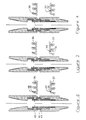
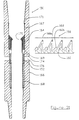
- FIG. 1 of the drawings illustrates a bypass tool 20 in accordance with an embodiment of the present invention.
- the tool has a tubular body 22 defining a through bore 24, the ends of the body 22 being provided with conventional pin and box connections 26, 27 to allow the tool 20 to form part of a drill string formed of sections of drill pipe.
- the tool 20 further comprises a fluid pressure actuated member in the form of an inner sleeve 28 which is axially movable relative to the body 22.
- a tool function member in the form of an outer valve sleeve 30, also axially movable relative to the body 22 and with seals 31 between the sleeve 30 and the body 22.
- the sleeve 30 is mounted such that it cannot rotate relative to the body 22.
- Both sleeves 28, 30 are biased upwardly within the body by respective springs 32, 33.
- the movement of the sleeves 28, 30 relative to the body 22 and relative to one another is controlled by two track and follower arrangements 34, 35, details of which are shown in Figure 1.
- the upper track 36 is defined in an outer surface portion of the inner sleeve 28 and extends around the circumference of the sleeve 28.
- the lower track 37 is defined by a collar rotatably mounted to the lower end of the sleeve 28.
- the tracks 36, 37 are mirror images of one another.
- a follower 38 extending radially inwardly from an upper portion of the outer sleeve 30 engages with the upper track 36, while a follower 39 extending inwardly of the body 22 engages with the lower track 37.
- the inner sleeve 28 defines a through bore, of corresponding diameter to the body bore 24, and is provided with a flow restriction 42 such that, above a certain flowrate, a pressure differential is created across the restriction 42 to produce a downward acting pressure force on the sleeve 28 sufficient to overcome the action of the spring 32.
- a pressure differential may also be produced sufficient to compress the heavier outer sleeve spring 33.
- the inner sleeve 28 is slotted at 44.
- the valve sleeve 30 and the body 22 each define radially extending flow ports 45, 46. Initially, the sleeve ports 45 are not aligned with the body ports 46. As will be described below, when the ports 45, 46 are aligned the tool provides for mud bypass, that is rather than all of the mud travelling down through the drill string and exiting at nozzles in the drill bit before passing up through the annulus, most of the mud passes directly from the string bore into the annulus, which may be useful in ensuring entrainment of drill cuttings.
- the track and follower arrangements 34, 35 are arranged such that the ports 45, 46 are only aligned after a predetermined sequence of pressure cycles, and after application of pressure forces above a predetermined level at a certain point on the cycle, and once opened the ports 45, 46 remain aligned until application of further pressure cycles above a predetermined level.
- Figure 1 illustrates the tool in an initial configuration and in which configuration the tool will remain as long as mud flow through the tool remains below a predetermined level, in this example 400 gallons per minute (gpm). If the mud flow is increased to more than 400 gpm, the pressure force created across the flow restriction 42 is sufficient to compress the spring 32, such that the inner sleeve 28 is moved downwardly relative to the body 22 and outer sleeve 30.
- the track followers 38, 39 travel along the respective tracks 36, 37.
- the configuration of the track 36 is such that the relative axial movement between the follower 38 and the crack 36 results in rotational movement of the inner sleeve 28 which moves downwardly in the body 22 until the followers 38, 39 engage respective track stops 48, 49.
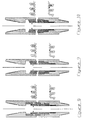
- the spring 32 lifts the inner sleeve 28 such that the sleeve 28 returns to its initial position, and the upper follower 38 engages the track stop 54 and the lower follower 39 engages the track stop 55, as illustrated in Figure 5 of the drawings.
- the spring 33 is selected such that, as long as the mud flow remains below 600 gpm, the outer sleeve 30 will not move downwards. If the mud flowrate is reduced once more, the spring 32 lifts the inner sleeve 28 and the followers 38, 39 advance to a position on the respective tracks 36, 37, as illustrated in Figure 7, corresponding to the initial position as illustrated in Figure 1. Thus, as long as the mud flow does not exceed 600 gpm while the sleeves 28, 30 are in the relative positions as illustrated in Figure 6 of the drawings, the ports 45, 46 will remain misaligned, and there will be no mud flow through the body ports 46.
- Figure 9 illustrates the relative positions of the sleeves 28, 30 and the body 22 when, starting from the relative positions as illustrated in Figure 5, mud flow has been increased to greater than 600 gpm. Accordingly, the pressure force acting on the inner sleeve 28 across the flow restriction 42 has not only compressed the spring 32 but has also compressed the spring 33 such that the pores 45, 46 are aligned. Once this relative positioning of the sleeves 28, 30 and body 22 has been achieved, the track configurations are arranged such that the ports 45, 46 remain aligned if the mud flow is reduced below 600 gpm (see Figure 10) and then increased above 600 gpm once more (see Figure 11).
- the configuration of the tool 20 is such that, as long as the pump flowrate remains below a predetermined level at selected points during the pressure cycle, the tool 20 may be subject to an indefinite number of cycles without opening.
- all that is required is for the mud flowrate to be varied and, at a certain point, to be increased above a predetermined flowrate, in this example 600 gpm. Further, once the tool 20 has been opened the tool will remain open through a predetermined number of further pressure cycles (below 600 gpm, above 600 gpm below 600 gpm).
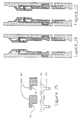
- Figures 14 to 29 of the drawings illustrate a bypass tool 60 in accordance with a preferred embodiment of the present invention.
- the tool 60 has a tubular body 62 defining a through bore 64, the ends of the body 62 being configured to allow the tool 60 to form part of a drill string formed of sections of drill pipe.
- the tool 60 further comprises an actuator sleeve 66 which defines a bore restriction 68 allowing a pressure force to be applied to the sleeve 66 by passing fluid through the body bore 64.
- a bypass sleeve 70 which is selectively coupled to the actuator sleeve 66, as will be described.
- the actuator sleeve 66 is axially movable and rotatable relative to the body 62, movement of the sleeve 66 being controlled by pins 72 which engage with a groove or track 74 defined by an inner face of the bypass sleeve, a track 74 and a number of pin locations being illustrated in Figure 15 of the drawings (it should be noted that in Figures 16 to 29 the bypass sleeve 70 appears to be rotating while the actuator sleeve 66 does not appear to rotate; the tool is illustrated in this manner to facilitate understanding of the tool operation). Also, the actuator sleeve 66 is biassed upwardly relative to the bypass sleeve 70 by an actuator spring 76 located below the track 74.
- flaps 78 Mounted in the portion of the actuator sleeve defining the bore restriction 68 are flaps 78 which, as will be described, may be extended into the body bore 64 to restrict fluid flow through the body 62, and allow application of significant fluid pressure forces to the sleeve 66.
- the flaps 78 are pivotally mounted to the sleeve 66 and the configuration of the flaps is controlled by the interaction of flap extensions 80 with profiled protrusions 82 on the bypass sleeve 70, as illustrated in Figure 15 of the drawings.
- the bypass sleeve 70 is axially movable relative to the body 62, the movement of the sleeve 70 being controlled by the interaction of pins 84 extending radially outwardly of the sleeve 70 and engaging a track 86 on a hold-down sleeve 88 rotatably mounted in the body 62.
- a heavy spring 90 is provided between the bypass sleeve 70 and the body 62 and tends to urge the sleeve 70 upwardly relatively to the body 62.
- another pin extends from the sleeve 70 to engage an axial slot in the body 62, to prevent rotation of the sleeve 70 relative to the body 62.
- bypass sleeve 70 defines ports 92 which, as will be described, may be selectively aligned with corresponding ports 94 in the body 62.
- Figure 16 illustrates the tool 60 in an initial or start position, with both the actuator sleeve 66 and the bypass sleeve 70 biassed toward upper positions by the respective sleeve springs 76, 90.
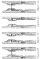
- the actuator sleeve 66 is moved downwardly by the pressure force created by the fluid passing through the bore restriction 68.
- the interaction of the pins 72 and the track 74 cause the sleeve 66 to rotate relative to the body 62 and the bypass sleeve 70 as the sleeve 66 moves axially downwards, to the position as illustrated in Figure 17.
- the actuator sleeve 66 moves upwardly, and rotates, and as the sleeve 66 moves upwardly the flap extensions 80 contact faces 96 of the protrusion 82, to extend the flaps 78, as shown in Figures 18 and 19. If the mud pumps are then turned on and pump slowly up to a first predetermined pressure (X) the actuator sleeve 66 moves downwards slightly and rotates, to the position as illustrated in Figure 20. If the pumps are then turned off, the actuator sleeve 66 moves upwardly again, rotates, and the flaps 78 fall open, as illustrated in Figure 16.
- X first predetermined pressure
- the initial movement of the actuator sleeve 66 is as described above, that is from the start position shown in Figure 16 the pumps are turned on full to move the actuator sleeve 66 down and also rotate the sleeve 66 to the position as shown in Figure 17. The pumps are then turned off, allowing the sleeve 66 to move upwardly and rotate and to extend the flaps, as illustrated in Figures 18 and 19. However, on turning on the pumps slowly again, the pressure produced by the pumps is increased to a higher second predetermined level (X+Y), which additional pressure also allows the bypass sleeve 70 to be moved downwardly, against the spring 90, by the action of the pins 72 on the bypass sleeve track 74. This position is illustrated in Figure 21 of the drawings.
- the bypass sleeve 70 moves partially upwards, restrained by the hold-down sleeve 88, which has rotated relative to the bypass sleeve 70, and the actuator sleeve 66 moves upwardly and rotates relative to the bypass sleeve 70, allowing the flaps 78 to fall open, as illustrated in Figures 22 and 23 of the drawings.
- the pumps may now be turned on fully, which causes the actuator sleeves 66 to move downwardly and rotate, and in which position the ports 92, 94 are aligned such that the majority of fluid flow is directed from the body bore 64, through the ports 92, 94, and into the annulus, as shown in Figure 24.
- the actuator sleeve 66 moves upwardly, rotates relative to the bypass sleeve 70, and the flap extensions 80 engage with the bypass sleeve protrusions 82 to extend the flaps 78, as shown in Figure 25 of the drawings.
- the actuator sleeve 66 is moved downward partially, rotating relative to the bypass sleeve 70, and latterly in the downward stroke taking the bypass sleeve 70 fully downwardly, as illustrated in Figures 26 and 27 of the drawings.
- this embodiment of the invention offers significant advantages by the provision of the retractable restriction in the form of the flaps 78.
- a permanent bore restriction is introduced into the string, thus restricting drilling mud flow rates.
- the axial force which may be applied via a fixed nozzle is limited to typically around 1,000 pounds (minus friction and any spring force that must be overcome).
- extension of the flaps 78 creates a significant restriction in the bore, and it is estimated that a force in the region of 50,000 pounds would be available from a typical tool.
- a further advantage provided by the significant restriction created in the tool bore by the extended flaps 78, is that the tool may be functioned at very low mud circulating rates. In the illustrated example, this greatly extends the life of the seals around the ports 92, 94, due to the minimal flow across the seals as the tool is opening. Also, the provision of the flaps 78 allows the configuration of the tool to be determined from surface, from the high pressure that is produced at the relatively low flow rates, without functioning the tool. When the flaps are opened, losses are minimal due to the relatively modest bore restriction which is required to allow movement of the actuator sleeve 66.
- FIG. 30 of the drawings illustrates a bypass tool 100 in accordance with another embodiment of the invention.
- the tool 100 represents a less sophisticated embodiment of the invention, comprising a one-piece sleeve 102 defining a fixed flow restriction 104.
- the sleeve 102 is axially and rotatably movable within a tubular body 106, movement of the sleeve 102 being controlled by a track and follower arrangement 108; the track 110 is defined in an upper outer surface of the sleeve 102 and the follower 112 is in the form of pins extending radially inwardly from the body 106.
- the sleeve 102 is movable between a "closed” position (as illustrated) in which flow ports 114 in the body are closed by the sleeve 102, and an open or flow position in which sleeve ports 116 are aligned with the body ports 114, allowing fluid to flow from the tool bore directly into the surrounding annulus.
- the provision of the restriction 104 renders the sleeve 102 flow sensitive, that is the greater the fluid flow rate through the string of which the tool forms a part, the greater the differential pressure acting across the restriction 104, and the greater the axial force acting on the sleeve 102.
- Axial movement of the sleeve 102 towards the open or flow position is resisted by a pair of springs 118, 120 acting between the body 106 and the sleeve 102.
- the first spring 118 constantly urges the sleeve 102 upwardly, while the higher rated second spring 120 only acts on the sleeve 102 during certain points in the cycling of the sleeve 102, as described below.
- Figures 30 illustrates the tool in the position where there is little or no flow through the tool 100, such that the spring 118 biases the sleeve 102 upwardly to its fullest extent, the pin followers 112 occupying the lowermost stop 110a on the track 110.
- An increase in mud flow rate will push the sleeve 102 downwards, against the action of the spring 118, this axial movement being accompanied by rotation of the sleeve 102 such that the pin followers 112 will move to the stop 110b on the track 110.
- the sleeve and body ports 116, 114 remain misaligned. Further axial movement of the sleeve 102 requires that the second spring 120 is compressed, this requiring an elevated mud flow rate.
- a subsequent increase in mud flow rate will move the sleeve 102 and bring the pin followers 112 into contact with the stops 110e; in this position the sleeve 102 is restrained from further downward movement, whatever the pressure differential across the restriction 104.
- the tool 100 may be cycled indefinitely and will only "open" when an elevated mud flow is provided at a particular part of the cycle; the drilling operators need not spend time cycling the tool in order to close the tool as a result of the normal variations in mud flow experienced during a drilling operation.
- FIGS 31 and 32 of the drawings illustrate a bypass tool 150 in accordance with another embodiment of the invention.
- This tool 150 features a two-part sleeve 152, the parts of the sleeve 154, 156, being selectively coupled by a track and follower arrangement 158 as illustrated in Figure 31, the track 160 being defined by on outer face of the first sleeve 154 and pin followers 162 being provided on an upper inner portion of the second sleeve 156.
- Movement of the sleeves 154, 156 is controlled by the track and follower arrangement 158 in conjunction with a relatively light first spring 164 between the first sleeve 154 and the tool body 166 and pre-tensioned heavier second spring 168 between the second sleeve 156 and the body 166.
- the first spring 164 is mounted to the body 166 via a spacer sleeve 167 retained in the body between a shoulder 169 and a circlip 171.
- the first sleeve 154 defines a restriction 170 such that the flow of mud through the tool 150 creates an axial pressure force on the sleeve 154; the sleeve 154 is illustrated in the position it would assume under full flow, with the location of the followers 162 in the track 160a allowing the sleeve 154 to be moved to its maximum extent without such movement being transferred to the other sleeve 156.
Description
Claims (26)
- A downhole tool (20) comprising:a body (22);a tool function member (28, 30) axially movable relative to the body from an initial position to an operative position;first means (32) responsive to a first force for permitting movement of the tool function member from the initial position to an intermediate position; andsecond means (33) responsive to a higher second force for selectively permitting movement of the tool function member to the operative position.
- The tool of claim 1, wherein the tool function member is fluid pressure actuated and the first means is responsive to a first fluid pressure force and the second means is responsive to a higher second fluid pressure force.
- The tool of claim 2, wherein the tool function member is actuated by flow induced fluid pressure forces.
- The tool of claim 3, wherein the tool function member is operatively associated with a flow restriction.
- The tool of claim 4, wherein the flow restriction is fixed.
- The tool of claim 4, wherein the flow restriction is variable.
- The tool of claim 6, wherein the flow restriction is movable between a first configuration, in which said restriction presents a minimal flow restriction, and a flow restricting second configuration and in said second configuration said restriction facilitates actuation of said tool function member.
- The tool of claim 7, wherein the flow restriction includes one or more selectively extendable and retractable flaps.
- The tool of claim 8, wherein in a first configuration the flaps extend radially inwardly to restrict flow through a tool bore.
- The tool of any of the preceding claims, wherein the first and second means are springs.
- The tool of claim 10, wherein the first and second means are a pair of springs, a first spring permitting movement of the member to the intermediate position and a second spring only permitting movement to the operative position on application of the higher second fluid pressure force.
- The tool of any of the preceding claims, wherein the tool function member is rotatable relative to the body.
- The tool of any of the preceding claims, wherein the tool function member is a sleeve.
- The tool of any of the preceding claims, wherein the movement of the tool function member relative to the body is controlled by a track and follower arrangement.
- The tool of any of the preceding claims, wherein the tool function member is in two or more parts, coupled by means for selectively coupling the parts.
- The tool of claim 15, wherein the tool function member comprises a fluid pressure actuated part axially movable relative to the body, and a tool function part axially movable relative to the body to one or more operative positions, and the tool further comprises means for selectively coupling the fluid pressure actuated part to the tool function part to permit movement of said tool function part to the one or more operative positions.
- The tool of claim 16, wherein in a first configuration said coupling means permits axial movement of the fluid pressure actuated part substantially independently of the tool function part, and in a second configuration axial movement of the fluid pressure actuated part results in corresponding axial movement of the tool function part.
- The tool of claim 16 or 17, wherein the fluid pressure actuated part is biassed towards the initial position by the first means and the tool function part is biassed towards the initial position by said second means.
- The tool of claim 16, 17 or 18, wherein the coupling means comprises a track and follower arrangement configurable to restrict relative movement between the fluid pressure actuated part and the tool function part.
- The tool of claim 19, wherein the coupling means further comprises a further track and follower arrangement to selectively restrict movement of the fluid pressure actuated part relative to the body.
- The tool of any of the preceding claims, wherein the tool is a fluid bypass tool, and in the operative position the tool function member permits fluid flow between a tool bore and the tool exterior.
- A downhole tool (20) comprising:a body (22);a tool function member (28, 30) axially movable relative to the body; anda fluid pressure actuated member operatively associated with the tool function member and including restriction means for restricting fluid flow through the body, said restriction means being movable between a first configuration, in which said means presents a minimal flow restriction, and a flow restricting second configuration, whereby in said second configuration said means facilitates movement of the fluid actuated member and actuation of said tool function member.
- The tool of claim 22, wherein the restriction means includes one or more selectively extendable and retractable flaps.
- The tool of claim 23, wherein in a first configuration the flaps extend radially inwardly to restrict flow through a tool bore.
- A downhole tool (20) comprising:a body (22);a fluid pressure actuated member axially movable relative to the body;a tool function member (28, 30) which is not responsive to fluid pressure and is axially movable relative to the body to an operative position; andmeans for selectively coupling the fluid pressure actuated member to the tool function member to permit movement of said tool function member to the operative position.
- A method of remotely activating a downhole tool (20), the method comprising:providing a downhole tool comprising a body (22), a fluid pressure actuated member axially movable relative to the body and a tool function member which is not responsive to fluid pressure and is axially movable relative to the body;selectively coupling the fluid pressure actuated member to the tool function member; andapplying fluid pressure to said fluid pressure actuated member to move the members axially relative to the body, thereby moving the tool function member to an operative position.
Applications Claiming Priority (5)
| Application Number | Priority Date | Filing Date | Title |
|---|---|---|---|
| GBGB9805413.3A GB9805413D0 (en) | 1998-03-14 | 1998-03-14 | Downhole tool |
| GB9805413 | 1998-03-14 | ||
| GBGB9902398.8A GB9902398D0 (en) | 1999-02-03 | 1999-02-03 | Downhole tool |
| GB9902398 | 1999-02-03 | ||
| PCT/GB1999/000754 WO1999047789A1 (en) | 1998-03-14 | 1999-03-12 | Pressure actuated downhole tool |
Publications (2)
| Publication Number | Publication Date |
|---|---|
| EP1064451A1 EP1064451A1 (en) | 2001-01-03 |
| EP1064451B1 true EP1064451B1 (en) | 2002-12-11 |
Family
ID=26313280
Family Applications (1)
| Application Number | Title | Priority Date | Filing Date |
|---|---|---|---|
| EP99907780A Expired - Lifetime EP1064451B1 (en) | 1998-03-14 | 1999-03-12 | Pressure actuated downhole tool |
Country Status (8)
| Country | Link |
|---|---|
| US (1) | US6378612B1 (en) |
| EP (1) | EP1064451B1 (en) |
| AU (1) | AU751132B2 (en) |
| CA (1) | CA2322863C (en) |
| DE (1) | DE69904456T2 (en) |
| DK (1) | DK1064451T3 (en) |
| NO (1) | NO319116B1 (en) |
| WO (1) | WO1999047789A1 (en) |
Cited By (2)
| Publication number | Priority date | Publication date | Assignee | Title |
|---|---|---|---|---|
| CN103437729A (en) * | 2013-08-29 | 2013-12-11 | 成都科盛石油科技有限公司 | By-pass valve with limiting structure |
| CN108533199A (en) * | 2018-03-20 | 2018-09-14 | 西南石油大学 | A kind of cycle controlled bypass valve |
Families Citing this family (56)
| Publication number | Priority date | Publication date | Assignee | Title |
|---|---|---|---|---|
| US6237683B1 (en) * | 1996-04-26 | 2001-05-29 | Camco International Inc. | Wellbore flow control device |
| GB9916513D0 (en) | 1999-07-15 | 1999-09-15 | Churchill Andrew P | Bypass tool |
| US7275602B2 (en) * | 1999-12-22 | 2007-10-02 | Weatherford/Lamb, Inc. | Methods for expanding tubular strings and isolating subterranean zones |
| US6364037B1 (en) | 2000-04-11 | 2002-04-02 | Weatherford/Lamb, Inc. | Apparatus to actuate a downhole tool |
| GB2362399B (en) * | 2000-05-19 | 2004-06-23 | Smith International | Improved bypass valve |
| US6782951B2 (en) * | 2002-05-08 | 2004-08-31 | Jeff L. Taylor | Flow-activated valve and method of use |
| US6945331B2 (en) | 2002-07-31 | 2005-09-20 | Schlumberger Technology Corporation | Multiple interventionless actuated downhole valve and method |
| US7077212B2 (en) | 2002-09-20 | 2006-07-18 | Weatherford/Lamb, Inc. | Method of hydraulically actuating and mechanically activating a downhole mechanical apparatus |
| US7451809B2 (en) * | 2002-10-11 | 2008-11-18 | Weatherford/Lamb, Inc. | Apparatus and methods for utilizing a downhole deployment valve |
| US7178600B2 (en) * | 2002-11-05 | 2007-02-20 | Weatherford/Lamb, Inc. | Apparatus and methods for utilizing a downhole deployment valve |
| US7090020B2 (en) * | 2002-10-30 | 2006-08-15 | Schlumberger Technology Corp. | Multi-cycle dump valve |
| US7228914B2 (en) * | 2003-11-03 | 2007-06-12 | Baker Hughes Incorporated | Interventionless reservoir control systems |
| EP1815104A4 (en) * | 2003-11-05 | 2010-05-05 | Drilling Solutions Pty Ltd | Actuating mechanism |
| US8066059B2 (en) | 2005-03-12 | 2011-11-29 | Thru Tubing Solutions, Inc. | Methods and devices for one trip plugging and perforating of oil and gas wells |
| GB0507408D0 (en) * | 2005-04-13 | 2005-05-18 | Petrowell Ltd | Apparatus |
| GB0513140D0 (en) | 2005-06-15 | 2005-08-03 | Lee Paul B | Novel method of controlling the operation of a downhole tool |
| WO2007005765A1 (en) * | 2005-06-30 | 2007-01-11 | M-I L.L.C. | Downhole multi-action jetting tool |
| CA2630916A1 (en) * | 2005-11-24 | 2007-05-31 | Churchill Drilling Tools Limited | Downhole tool |
| AU2012200315B2 (en) * | 2007-01-16 | 2014-01-16 | Baker Hughes Incorporated | Multiple dart drop circulating tool |
| US7520336B2 (en) * | 2007-01-16 | 2009-04-21 | Bj Services Company | Multiple dart drop circulating tool |
| US7766086B2 (en) * | 2007-06-08 | 2010-08-03 | Bj Services Company Llc | Fluid actuated circulating sub |
| GB0716049D0 (en) * | 2007-08-17 | 2007-09-26 | Welltools Ltd | Switchable circulating tool |
| US7703510B2 (en) * | 2007-08-27 | 2010-04-27 | Baker Hughes Incorporated | Interventionless multi-position frac tool |
| US8006779B2 (en) * | 2009-02-18 | 2011-08-30 | Halliburton Energy Services, Inc. | Pressure cycle operated perforating firing head |
| US20110042100A1 (en) * | 2009-08-18 | 2011-02-24 | O'neal Eric | Wellbore circulation assembly |
| EP2483510A2 (en) | 2009-09-30 | 2012-08-08 | Baker Hughes Incorporated | Remotely controlled apparatus for downhole applications and methods of operation |
| US9175520B2 (en) * | 2009-09-30 | 2015-11-03 | Baker Hughes Incorporated | Remotely controlled apparatus for downhole applications, components for such apparatus, remote status indication devices for such apparatus, and related methods |
| US8448700B2 (en) | 2010-08-03 | 2013-05-28 | Thru Tubing Solutions, Inc. | Abrasive perforator with fluid bypass |
| WO2012100259A2 (en) | 2011-01-21 | 2012-07-26 | Weatherford/Lamb, Inc. | Telemetry operated circulation sub |
| US9920600B2 (en) | 2011-06-10 | 2018-03-20 | Schlumberger Technology Corporation | Multi-stage downhole hydraulic stimulation assembly |
| US9228422B2 (en) | 2012-01-30 | 2016-01-05 | Thru Tubing Solutions, Inc. | Limited depth abrasive jet cutter |
| US9453388B2 (en) * | 2012-04-11 | 2016-09-27 | MIT Innovation Sdn Bhd | Apparatus and method to remotely control fluid flow in tubular strings and wellbore annulus |
| US9133682B2 (en) | 2012-04-11 | 2015-09-15 | MIT Innovation Sdn Bhd | Apparatus and method to remotely control fluid flow in tubular strings and wellbore annulus |
| AU2013245814A1 (en) * | 2012-04-11 | 2014-11-20 | MIT Innovation Sdn Bhd | Apparatus and method to remotely control fluid flow in tubular strings and wellbore annulus |
| US9404326B2 (en) * | 2012-04-13 | 2016-08-02 | Saudi Arabian Oil Company | Downhole tool for use in a drill string |
| US10151174B2 (en) | 2012-07-05 | 2018-12-11 | Allamon Properties Llc | Multi-function surge reduction apparatus |
| US9328579B2 (en) | 2012-07-13 | 2016-05-03 | Weatherford Technology Holdings, Llc | Multi-cycle circulating tool |
| GB2507770A (en) * | 2012-11-08 | 2014-05-14 | Petrowell Ltd | Downhole activation tool |
| US9187978B2 (en) | 2013-03-11 | 2015-11-17 | Weatherford Technology Holdings, Llc | Expandable ball seat for hydraulically actuating tools |
| CN105934560A (en) | 2014-02-24 | 2016-09-07 | 哈里伯顿能源服务公司 | Regulation of flow through well tool string |
| NO339673B1 (en) * | 2014-06-03 | 2017-01-23 | Trican Completion Solutions Ltd | Flow controlled downhole tool |
| CN105317400B (en) * | 2014-08-04 | 2018-08-14 | 中国石油化工股份有限公司 | Control valve for fluids |
| US10018039B2 (en) * | 2014-09-19 | 2018-07-10 | Saudi Arabian Oil Company | Fast-setting retrievable slim-hole test packer and method of use |
| WO2016042328A1 (en) * | 2014-09-20 | 2016-03-24 | Weatherford U.K. Limited | Pressure operated valve assembly |
| CA2911551C (en) | 2014-11-07 | 2020-03-24 | Dick S. GONZALEZ | Indexing stimulating sleeve and other downhole tools |
| US10344560B2 (en) * | 2014-11-11 | 2019-07-09 | Interra Energy Services Ltd. | Wellbore tool with pressure actuated indexing mechanism and method |
| US9915354B2 (en) * | 2014-12-19 | 2018-03-13 | Schlumberger Technology Corporation | Rotary check valve |
| GB201519684D0 (en) * | 2015-11-06 | 2015-12-23 | Cutting & Wear Resistant Dev | Circulation subassembly |
| GB201600468D0 (en) * | 2016-01-11 | 2016-02-24 | Paradigm Flow Services Ltd | Fluid discharge apparatus and method of use |
| GB2553834A (en) * | 2016-09-16 | 2018-03-21 | Schoeller Bleckmann Oilfield Equipment Ag | Splitflow valve |
| US10677024B2 (en) | 2017-03-01 | 2020-06-09 | Thru Tubing Solutions, Inc. | Abrasive perforator with fluid bypass |
| US10794135B2 (en) * | 2017-04-03 | 2020-10-06 | Charles Abernethy Anderson | Differential pressure actuation tool and method of use |
| BR112021006589B1 (en) | 2018-12-05 | 2024-03-05 | Halliburton Energy Services, Inc | DOWNWELL TOOL, DRIVE ASSEMBLY POSITIONABLE WITHIN A WELL HOLE AND METHOD FOR DRIVING A TOOL POSITIONED DOWNWELL IN A WELL HOLE |
| US11346183B2 (en) | 2018-12-05 | 2022-05-31 | Halliburton Energy Services, Inc. | Multi-piston activation mechanism |
| CN110107237B (en) * | 2019-04-23 | 2021-09-17 | 成都众智诚成石油科技有限公司 | Bypass valve for downhole pipe column and use method thereof |
| US10907444B1 (en) * | 2019-07-09 | 2021-02-02 | Baker Hughes Oilfield Operations Llc | Choke system for a downhole valve |
Family Cites Families (11)
| Publication number | Priority date | Publication date | Assignee | Title |
|---|---|---|---|---|
| US4377179A (en) * | 1980-10-28 | 1983-03-22 | Bernhardt & Frederick Co., Inc. | Pressure balanced ball valve device |
| US4432417A (en) * | 1981-10-02 | 1984-02-21 | Baker International Corporation | Control pressure actuated downhole hanger apparatus |
| US4624311A (en) * | 1985-09-26 | 1986-11-25 | Baker Oil Tools, Inc. | Locking mechanism for hydraulic running tool for well hangers and the like |
| US5052489A (en) * | 1990-06-15 | 1991-10-01 | Carisella James V | Apparatus for selectively actuating well tools |
| GB2256884A (en) * | 1991-06-21 | 1992-12-23 | Pbl Drilling Tools Limited | Tubular fitting for use in a drilling string |
| GB2272923B (en) * | 1992-11-16 | 1995-05-24 | Mark Carmichael | Apparatus for circulating fluid |
| US5609178A (en) * | 1995-09-28 | 1997-03-11 | Baker Hughes Incorporated | Pressure-actuated valve and method |
| GB9525008D0 (en) * | 1995-12-07 | 1996-02-07 | Red Baron Oil Tools Rental | Bypass valve |
| GB9601659D0 (en) * | 1996-01-27 | 1996-03-27 | Paterson Andrew W | Apparatus for circulating fluid in a borehole |
| AU722886B2 (en) * | 1996-04-18 | 2000-08-10 | Halliburton Energy Services, Inc. | Circulating valve responsive to fluid flow rate therethrough and associated methods of servicing a well |
| US5947205A (en) * | 1996-06-20 | 1999-09-07 | Halliburton Energy Services, Inc. | Linear indexing apparatus with selective porting |
-
1999
- 1999-03-12 AU AU27407/99A patent/AU751132B2/en not_active Ceased
- 1999-03-12 EP EP99907780A patent/EP1064451B1/en not_active Expired - Lifetime
- 1999-03-12 DE DE69904456T patent/DE69904456T2/en not_active Expired - Fee Related
- 1999-03-12 DK DK99907780T patent/DK1064451T3/en active
- 1999-03-12 CA CA002322863A patent/CA2322863C/en not_active Expired - Fee Related
- 1999-03-12 WO PCT/GB1999/000754 patent/WO1999047789A1/en active IP Right Grant
- 1999-03-12 US US09/646,196 patent/US6378612B1/en not_active Expired - Fee Related
-
2000
- 2000-08-31 NO NO20004336A patent/NO319116B1/en not_active IP Right Cessation
Cited By (2)
| Publication number | Priority date | Publication date | Assignee | Title |
|---|---|---|---|---|
| CN103437729A (en) * | 2013-08-29 | 2013-12-11 | 成都科盛石油科技有限公司 | By-pass valve with limiting structure |
| CN108533199A (en) * | 2018-03-20 | 2018-09-14 | 西南石油大学 | A kind of cycle controlled bypass valve |
Also Published As
| Publication number | Publication date |
|---|---|
| NO20004336D0 (en) | 2000-08-31 |
| AU2740799A (en) | 1999-10-11 |
| AU751132B2 (en) | 2002-08-08 |
| WO1999047789A1 (en) | 1999-09-23 |
| DE69904456T2 (en) | 2003-10-02 |
| CA2322863A1 (en) | 1999-09-23 |
| DK1064451T3 (en) | 2003-03-03 |
| CA2322863C (en) | 2007-05-29 |
| NO20004336L (en) | 2000-11-03 |
| DE69904456D1 (en) | 2003-01-23 |
| EP1064451A1 (en) | 2001-01-03 |
| US6378612B1 (en) | 2002-04-30 |
| NO319116B1 (en) | 2005-06-20 |
Similar Documents
| Publication | Publication Date | Title |
|---|---|---|
| EP1064451B1 (en) | Pressure actuated downhole tool | |
| US10190376B2 (en) | Apparatus and method for controlling a downhole device | |
| CA2440922C (en) | Downhole tool | |
| AU2012343563C1 (en) | Apparatus and method for controlling a downhole device | |
| US5901796A (en) | Circulating sub apparatus | |
| US8607811B2 (en) | Injection valve with indexing mechanism | |
| RU2358092C2 (en) | Back valve switched by flow | |
| WO2009024753A1 (en) | Switchable circulating tool | |
| US20230068934A1 (en) | Flow Diversion Valve for Downtool Tool Assembly | |
| US11867013B2 (en) | Flow diversion valve for downhole tool assembly | |
| WO1998023841A1 (en) | Apparatus and method for circulating fluid in a borehole | |
| EP2834547A2 (en) | Downhole actuator | |
| EP0787888B1 (en) | Circulating sub | |
| CA2196857C (en) | A circulating sub apparatus |
Legal Events
| Date | Code | Title | Description |
|---|---|---|---|
| PUAI | Public reference made under article 153(3) epc to a published international application that has entered the european phase |
Free format text: ORIGINAL CODE: 0009012 |
|
| 17P | Request for examination filed |
Effective date: 20000927 |
|
| AK | Designated contracting states |
Kind code of ref document: A1 Designated state(s): DE DK FR GB IT NL |
|
| GRAG | Despatch of communication of intention to grant |
Free format text: ORIGINAL CODE: EPIDOS AGRA |
|
| 17Q | First examination report despatched |
Effective date: 20010720 |
|
| GRAG | Despatch of communication of intention to grant |
Free format text: ORIGINAL CODE: EPIDOS AGRA |
|
| GRAH | Despatch of communication of intention to grant a patent |
Free format text: ORIGINAL CODE: EPIDOS IGRA |
|
| GRAH | Despatch of communication of intention to grant a patent |
Free format text: ORIGINAL CODE: EPIDOS IGRA |
|
| GRAA | (expected) grant |
Free format text: ORIGINAL CODE: 0009210 |
|
| AK | Designated contracting states |
Kind code of ref document: B1 Designated state(s): DE DK FR GB IT NL |
|
| REG | Reference to a national code |
Ref country code: GB Ref legal event code: FG4D |
|
| REF | Corresponds to: |
Ref document number: 69904456 Country of ref document: DE Date of ref document: 20030123 |
|
| REG | Reference to a national code |
Ref country code: DK Ref legal event code: T3 |
|
| PG25 | Lapsed in a contracting state [announced via postgrant information from national office to epo] |
Ref country code: DK Free format text: LAPSE BECAUSE OF NON-PAYMENT OF DUE FEES Effective date: 20030331 |
|
| ET | Fr: translation filed | ||
| PLBE | No opposition filed within time limit |
Free format text: ORIGINAL CODE: 0009261 |
|
| STAA | Information on the status of an ep patent application or granted ep patent |
Free format text: STATUS: NO OPPOSITION FILED WITHIN TIME LIMIT |
|
| REG | Reference to a national code |
Ref country code: DK Ref legal event code: EBP |
|
| 26N | No opposition filed |
Effective date: 20030912 |
|
| PGFP | Annual fee paid to national office [announced via postgrant information from national office to epo] |
Ref country code: NL Payment date: 20060305 Year of fee payment: 8 |
|
| PGFP | Annual fee paid to national office [announced via postgrant information from national office to epo] |
Ref country code: FR Payment date: 20060308 Year of fee payment: 8 |
|
| PGFP | Annual fee paid to national office [announced via postgrant information from national office to epo] |
Ref country code: DE Payment date: 20060309 Year of fee payment: 8 |
|
| PGFP | Annual fee paid to national office [announced via postgrant information from national office to epo] |
Ref country code: IT Payment date: 20060331 Year of fee payment: 8 |
|
| NLV4 | Nl: lapsed or anulled due to non-payment of the annual fee |
Effective date: 20071001 |
|
| REG | Reference to a national code |
Ref country code: FR Ref legal event code: ST Effective date: 20071130 |
|
| PG25 | Lapsed in a contracting state [announced via postgrant information from national office to epo] |
Ref country code: NL Free format text: LAPSE BECAUSE OF NON-PAYMENT OF DUE FEES Effective date: 20071001 Ref country code: DE Free format text: LAPSE BECAUSE OF NON-PAYMENT OF DUE FEES Effective date: 20071002 |
|
| PG25 | Lapsed in a contracting state [announced via postgrant information from national office to epo] |
Ref country code: FR Free format text: LAPSE BECAUSE OF NON-PAYMENT OF DUE FEES Effective date: 20070402 |
|
| PGFP | Annual fee paid to national office [announced via postgrant information from national office to epo] |
Ref country code: GB Payment date: 20090311 Year of fee payment: 11 |
|
| PG25 | Lapsed in a contracting state [announced via postgrant information from national office to epo] |
Ref country code: IT Free format text: LAPSE BECAUSE OF NON-PAYMENT OF DUE FEES Effective date: 20070312 |
|
| GBPC | Gb: european patent ceased through non-payment of renewal fee |
Effective date: 20100312 |
|
| PG25 | Lapsed in a contracting state [announced via postgrant information from national office to epo] |
Ref country code: GB Free format text: LAPSE BECAUSE OF NON-PAYMENT OF DUE FEES Effective date: 20100312 |