EP3018238A1 - Horizontal heat treatment device and method for producing carbon fibers using horizontal heat treatment device - Google Patents
Horizontal heat treatment device and method for producing carbon fibers using horizontal heat treatment device Download PDFInfo
- Publication number
- EP3018238A1 EP3018238A1 EP14820559.4A EP14820559A EP3018238A1 EP 3018238 A1 EP3018238 A1 EP 3018238A1 EP 14820559 A EP14820559 A EP 14820559A EP 3018238 A1 EP3018238 A1 EP 3018238A1
- Authority
- EP
- European Patent Office
- Prior art keywords
- heat treatment
- workpiece
- chamber
- carbon
- treatment chamber
- Prior art date
- Legal status (The legal status is an assumption and is not a legal conclusion. Google has not performed a legal analysis and makes no representation as to the accuracy of the status listed.)
- Withdrawn
Links
- 238000010438 heat treatment Methods 0.000 title claims abstract description 302
- 229920000049 Carbon (fiber) Polymers 0.000 title claims description 53
- 239000004917 carbon fiber Substances 0.000 title claims description 53
- 238000004519 manufacturing process Methods 0.000 title description 10
- 238000007789 sealing Methods 0.000 claims abstract description 180
- 239000000835 fiber Substances 0.000 claims abstract description 45
- 239000002243 precursor Substances 0.000 claims abstract description 38
- 238000005192 partition Methods 0.000 claims abstract description 34
- VNWKTOKETHGBQD-UHFFFAOYSA-N methane Chemical compound C VNWKTOKETHGBQD-UHFFFAOYSA-N 0.000 claims description 52
- 238000000034 method Methods 0.000 claims description 13
- 238000007380 fibre production Methods 0.000 claims description 11
- 231100000614 poison Toxicity 0.000 abstract description 6
- 230000007096 poisonous effect Effects 0.000 abstract description 6
- 239000007789 gas Substances 0.000 description 42
- 230000003247 decreasing effect Effects 0.000 description 21
- 230000000052 comparative effect Effects 0.000 description 15
- 238000000197 pyrolysis Methods 0.000 description 11
- 239000000779 smoke Substances 0.000 description 11
- QGZKDVFQNNGYKY-UHFFFAOYSA-N Ammonia Chemical compound N QGZKDVFQNNGYKY-UHFFFAOYSA-N 0.000 description 8
- 238000005259 measurement Methods 0.000 description 8
- 230000007423 decrease Effects 0.000 description 6
- 238000011156 evaluation Methods 0.000 description 6
- 238000011144 upstream manufacturing Methods 0.000 description 6
- 239000000463 material Substances 0.000 description 5
- CURLTUGMZLYLDI-UHFFFAOYSA-N Carbon dioxide Chemical compound O=C=O CURLTUGMZLYLDI-UHFFFAOYSA-N 0.000 description 4
- XFXPMWWXUTWYJX-UHFFFAOYSA-N Cyanide Chemical compound N#[C-] XFXPMWWXUTWYJX-UHFFFAOYSA-N 0.000 description 4
- 229910021529 ammonia Inorganic materials 0.000 description 4
- 229910002090 carbon oxide Inorganic materials 0.000 description 4
- 230000000694 effects Effects 0.000 description 4
- 238000007254 oxidation reaction Methods 0.000 description 4
- 229920002239 polyacrylonitrile Polymers 0.000 description 4
- 238000002485 combustion reaction Methods 0.000 description 3
- 230000015556 catabolic process Effects 0.000 description 1
- 238000006731 degradation reaction Methods 0.000 description 1
- 238000006073 displacement reaction Methods 0.000 description 1
Images


Classifications
-
- D—TEXTILES; PAPER
- D01—NATURAL OR MAN-MADE THREADS OR FIBRES; SPINNING
- D01F—CHEMICAL FEATURES IN THE MANUFACTURE OF ARTIFICIAL FILAMENTS, THREADS, FIBRES, BRISTLES OR RIBBONS; APPARATUS SPECIALLY ADAPTED FOR THE MANUFACTURE OF CARBON FILAMENTS
- D01F9/00—Artificial filaments or the like of other substances; Manufacture thereof; Apparatus specially adapted for the manufacture of carbon filaments
- D01F9/08—Artificial filaments or the like of other substances; Manufacture thereof; Apparatus specially adapted for the manufacture of carbon filaments of inorganic material
- D01F9/12—Carbon filaments; Apparatus specially adapted for the manufacture thereof
- D01F9/14—Carbon filaments; Apparatus specially adapted for the manufacture thereof by decomposition of organic filaments
- D01F9/32—Apparatus therefor
- D01F9/328—Apparatus therefor for manufacturing filaments from polyaddition, polycondensation, or polymerisation products
-
- D—TEXTILES; PAPER
- D01—NATURAL OR MAN-MADE THREADS OR FIBRES; SPINNING
- D01F—CHEMICAL FEATURES IN THE MANUFACTURE OF ARTIFICIAL FILAMENTS, THREADS, FIBRES, BRISTLES OR RIBBONS; APPARATUS SPECIALLY ADAPTED FOR THE MANUFACTURE OF CARBON FILAMENTS
- D01F9/00—Artificial filaments or the like of other substances; Manufacture thereof; Apparatus specially adapted for the manufacture of carbon filaments
- D01F9/08—Artificial filaments or the like of other substances; Manufacture thereof; Apparatus specially adapted for the manufacture of carbon filaments of inorganic material
- D01F9/12—Carbon filaments; Apparatus specially adapted for the manufacture thereof
- D01F9/14—Carbon filaments; Apparatus specially adapted for the manufacture thereof by decomposition of organic filaments
- D01F9/32—Apparatus therefor
-
- F—MECHANICAL ENGINEERING; LIGHTING; HEATING; WEAPONS; BLASTING
- F27—FURNACES; KILNS; OVENS; RETORTS
- F27B—FURNACES, KILNS, OVENS OR RETORTS IN GENERAL; OPEN SINTERING OR LIKE APPARATUS
- F27B9/00—Furnaces through which the charge is moved mechanically, e.g. of tunnel type; Similar furnaces in which the charge moves by gravity
- F27B9/02—Furnaces through which the charge is moved mechanically, e.g. of tunnel type; Similar furnaces in which the charge moves by gravity of multiple-track type; of multiple-chamber type; Combinations of furnaces
-
- F—MECHANICAL ENGINEERING; LIGHTING; HEATING; WEAPONS; BLASTING
- F27—FURNACES; KILNS; OVENS; RETORTS
- F27B—FURNACES, KILNS, OVENS OR RETORTS IN GENERAL; OPEN SINTERING OR LIKE APPARATUS
- F27B9/00—Furnaces through which the charge is moved mechanically, e.g. of tunnel type; Similar furnaces in which the charge moves by gravity
- F27B9/28—Furnaces through which the charge is moved mechanically, e.g. of tunnel type; Similar furnaces in which the charge moves by gravity for treating continuous lengths of work
-
- F—MECHANICAL ENGINEERING; LIGHTING; HEATING; WEAPONS; BLASTING
- F27—FURNACES; KILNS; OVENS; RETORTS
- F27D—DETAILS OR ACCESSORIES OF FURNACES, KILNS, OVENS OR RETORTS, IN SO FAR AS THEY ARE OF KINDS OCCURRING IN MORE THAN ONE KIND OF FURNACE
- F27D7/00—Forming, maintaining or circulating atmospheres in heating chambers
- F27D7/06—Forming or maintaining special atmospheres or vacuum within heating chambers
-
- F—MECHANICAL ENGINEERING; LIGHTING; HEATING; WEAPONS; BLASTING
- F27—FURNACES; KILNS; OVENS; RETORTS
- F27D—DETAILS OR ACCESSORIES OF FURNACES, KILNS, OVENS OR RETORTS, IN SO FAR AS THEY ARE OF KINDS OCCURRING IN MORE THAN ONE KIND OF FURNACE
- F27D99/00—Subject matter not provided for in other groups of this subclass
- F27D99/007—Partitions
-
- F—MECHANICAL ENGINEERING; LIGHTING; HEATING; WEAPONS; BLASTING
- F27—FURNACES; KILNS; OVENS; RETORTS
- F27D—DETAILS OR ACCESSORIES OF FURNACES, KILNS, OVENS OR RETORTS, IN SO FAR AS THEY ARE OF KINDS OCCURRING IN MORE THAN ONE KIND OF FURNACE
- F27D99/00—Subject matter not provided for in other groups of this subclass
- F27D99/0073—Seals
-
- C—CHEMISTRY; METALLURGY
- C21—METALLURGY OF IRON
- C21D—MODIFYING THE PHYSICAL STRUCTURE OF FERROUS METALS; GENERAL DEVICES FOR HEAT TREATMENT OF FERROUS OR NON-FERROUS METALS OR ALLOYS; MAKING METAL MALLEABLE, e.g. BY DECARBURISATION OR TEMPERING
- C21D9/00—Heat treatment, e.g. annealing, hardening, quenching or tempering, adapted for particular articles; Furnaces therefor
- C21D9/52—Heat treatment, e.g. annealing, hardening, quenching or tempering, adapted for particular articles; Furnaces therefor for wires; for strips ; for rods of unlimited length
- C21D9/54—Furnaces for treating strips or wire
- C21D9/56—Continuous furnaces for strip or wire
- C21D9/562—Details
- C21D9/565—Sealing arrangements
-
- D—TEXTILES; PAPER
- D10—INDEXING SCHEME ASSOCIATED WITH SUBLASSES OF SECTION D, RELATING TO TEXTILES
- D10B—INDEXING SCHEME ASSOCIATED WITH SUBLASSES OF SECTION D, RELATING TO TEXTILES
- D10B2101/00—Inorganic fibres
- D10B2101/10—Inorganic fibres based on non-oxides other than metals
- D10B2101/12—Carbon; Pitch
Definitions
- the present invention is made to solve the above-described problems, and an objective of the present invention is to provide a horizontal heat treatment apparatus capable of decreasing unevenness in temperature inside a heat treatment chamber, ensuring stability in process, and improving uniformity in quality by increasing the temperature of a workpiece conveyed to the heat treatment chamber while efficiently performing a heat exchange in the workpieces and completely suppressing a poisonous gas produced inside the heat treatment chamber from leaking to external air without particularly demanding a large-scale facility and to provide a carbon fiber production method using the horizontal heat treatment apparatus.
- the number of the heat transfer zones in the condition (a) be 10% or more of the number of all zones inside the sealing chambers. Then, it is desirable that the number of times of causing the workpiece to travel through inside of the heat treatment chamber in the steps defined in the condition (b) be 10% or more of the number of times of causing the workpiece to travel through inside of the heat treatment chamber.
- the dimensions of the sealing device and the folding roll were measured with a tape measure.
- an evaluation of "non-existence of strain” was given.
- an evaluation of "existence of slight strain” was given.
- an evaluation of "existence of strain” was given.
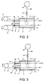
- the inside of the sealing chamber 4 was defined by the partition plates 11 so that the number of all zones was eight and the number of the heat transfer zones (a) therein was two. As shown in Fig. 3 , in each of the heat transfer zones (a), traveling of the workpiece A in the horizontal direction was defined every two stages, and was defined every stage in the zones other than the heat transfer zones (a).
Landscapes
- Engineering & Computer Science (AREA)
- Mechanical Engineering (AREA)
- General Engineering & Computer Science (AREA)
- Manufacturing & Machinery (AREA)
- Chemical & Material Sciences (AREA)
- Chemical Kinetics & Catalysis (AREA)
- General Chemical & Material Sciences (AREA)
- Textile Engineering (AREA)
- Inorganic Fibers (AREA)
- Tunnel Furnaces (AREA)
- Furnace Details (AREA)
Abstract
Description
- The present invention relates to a horizontal heat treatment apparatus which completely suppresses a poisonous gas produced inside a heat treatment chamber from leaking to external air and improves energy efficiency and a carbon fiber production method which uses the horizontal heat treatment apparatus.
- The present invention relates to a horizontal heat treatment apparatus which continuously performs a heat treatment on a continuous flat workpiece such as a fiber sheet and a carbon fiber production method which uses the horizontal heat treatment apparatus, and more particularly, to a heat treatment apparatus which is appropriately used in a flame proofing furnace that performs a heat treatment on a carbon-fiber precursor fiber bundle when a carbon fiber is produced.
- Hitherto, there is known a heat treatment apparatus which continuously performs a heat treatment on a workpiece when an elongated material such as a film, a sheet, and a fiber (hereinafter, referred to as a workpiece) is produced. In the case of an example of a carbon fiber, the heat treatment apparatus is used to continuously perform a heat treatment on, for example, a carbon-fiber precursor fiber bundle formed of a poly acrylonitrile fiber inside a heat treatment chamber. At this time, a pyrolysis gas such as cyanide, ammonia, and carbon oxide is produced inside the heat treatment chamber due to an oxidization reaction of the carbon-fiber precursor fiber bundle. The pyrolysis gas needs to be collected and subjected to a gas treatment such as a combustion process.
- Due to the oxidization reaction of the flame proofing treatment, a pyrolysis gas such as cyanide, ammonia, and carbon oxide is produced inside the heat treatment chamber. Furthermore, in a case where the workpiece is conveyed into and out from the heat treatment chamber, an entrance and an exit for the workpiece are essentially provided in the heat treatment apparatus. Further, a sealing chamber for close guard is provided so that the gas inside the heat treatment chamber does not leak from the entrance and the exit to the outside of the furnace.
- Patent Document 1 discloses a heat treatment apparatus in which a sealing chamber is defined in the vertical direction by a partition plate and one exhaust port is provided in each of the defined sealing chambers so as to adjust the pressure of each sealing chamber. For that reason, the heat treatment apparatus is able to separately control a pressure difference between the inside of a heat treatment chamber and the inside of the sealing chamber, is able to control external air flowing into the heat treatment chamber or hot air excessively flowing from the heat treatment chamber due to an influence of a difference in buoyant force inside and outside the heat treatment chamber, and has an excellent uniform temperature.
-
Patent Document 2 discloses a heat treatment apparatus in which a sealing chamber is defined by a partition plate. For that reason, the heat treatment apparatus is able to appropriately adjust the pressure of each sealing chamber, is able to separately control a pressure difference between the inside of a heat treatment chamber and the inside of the sealing chamber, is able to control external air flowing into the heat treatment chamber or hot air excessively flowing out from the heat treatment chamber due to an influence of a difference in buoyant force inside and outside the heat treatment chamber, and has an excellent uniform temperature. -
Patent Document 3 discloses a heat treatment apparatus which prevents a pyrolysis gas from leaking from an entrance/the exit of a workpiece in the heat treatment apparatus to the outside of the heat treatment apparatus. Here, a sealing chamber is provided near a heat treatment chamber so that a negative pressure is formed therein and a pyrolysis gas is collected, and an air curtain unit is provided at the outside of an entrance/an exit of the workpiece in the sealing chamber so that air outside the heat treatment apparatus is ejected toward the workpiece and external air is suppressed from flowing thereinto. - As a method of solving an uneven temperature and degradation in energy efficiency of a heat treatment furnace caused by external air flowing thereinto,
Patent Document 4 discloses a heat treatment apparatus in which a sealing chamber is provided so that a horizontal slit-shaped opening portion through which a workpiece is conveyed is provided in a plurality of stages in the up and down direction of an outer side wall. Here, the heat treatment apparatus includes a gas ejection port which supplies a gas toward the upper or lower portion of the sealing chamber in the same direction as the direction of a heated gas of a heat treatment chamber and a gas suction port which suctions a gas in a direction facing the gas ejection port. -
- Patent Document 1:
JP 2007-132657 A - Patent Document 2:
JP 62-228866 A - Patent Document 3:
JP 2004-143647 A - Patent Document 4:
JP 2010-100967 A - An objective of the present invention is to completely suppress the poisonous gas produced inside the heat treatment chamber from leaking to external air and to efficiently perform a heat exchange in the workpieces.
- As disclosed in
Patent Document 4, when hot air is ejected in a direction orthogonal to the traveling direction of the workpiece, a large-scale facility is needed in order to prevent a gas from leaking to the outside of the furnace while ensuring the control of the temperature inside the heat treatment chamber. - The present invention is made to solve the above-described problems, and an objective of the present invention is to provide a horizontal heat treatment apparatus capable of decreasing unevenness in temperature inside a heat treatment chamber, ensuring stability in process, and improving uniformity in quality by increasing the temperature of a workpiece conveyed to the heat treatment chamber while efficiently performing a heat exchange in the workpieces and completely suppressing a poisonous gas produced inside the heat treatment chamber from leaking to external air without particularly demanding a large-scale facility and to provide a carbon fiber production method using the horizontal heat treatment apparatus.
- According to an aspect of the present invention, provided is a horizontal heat treatment apparatus that continuously performs a heat treatment on a continuous flat workpiece while moving the continuous flat workpiece in a reciprocating manner through a heat treatment chamber in a plurality of stages in the horizontal direction, wherein the following conditions (1) to (3) are satisfied: (1) the heat treatment chamber has sealing chambers which are connected to an entrance and an exit of the workpiece; (2) one or more partition plates having the workpiece traveling in the horizontal direction in both of the upper and lower sides are disposed inside the sealing chamber and zones defined in the vertical direction is formed by two partition plates or one partition plate and an inner wall of the sealing chamber; and (3) the partition plate is disposed so as to satisfy the following conditions (a) and (b): (a) the zones include one or more heat transfer zones in which the workpiece being conveyed into the heat treatment chamber is located higher in relation to the workpiece being conveyed out from the heat treatment chamber; and (b) one or more steps in which the workpiece firstly passes through one of the heat transfer zones inside one sealing chamber, secondly travels through inside of the heat treatment chamber, and thirdly passes through one of the heat transfer zones inside the other sealing chamber are included.
- It is desirable that the number of the heat transfer zones in the condition (a) be 10% or more of the number of all zones inside the sealing chambers. Then, it is desirable that the number of times of causing the workpiece to travel through inside of the heat treatment chamber in the steps defined in the condition (b) be 10% or more of the number of times of causing the workpiece to travel through inside of the heat treatment chamber.
- Further, it is desirable that the number of times of causing the workpiece to travel through each of the heat transfer zones defined in the condition (a) in a reciprocating manner be two to four. Then, it is more desirable that the number of times of causing the workpiece to travel through each of the heat transfer zones in the condition (a) be two and the number of times of causing the workpiece to travel through each of the zones inside the sealing chamber be three or less.
- At least one exhaust mechanism can be provided in each zone.
- Further, an air curtain mechanism or a slit-shaped nozzle can be provided so as to eject air from each zone toward a heat treatment apparatus entrance through which the workpiece is conveyed from the outside of the heat treatment apparatus into each zone and a heat treatment apparatus exit through which the workpiece is conveyed out from each zone to the outside of the heat treatment apparatus.
- The horizontal heat treatment apparatus can be used as a flame proofing furnace that performs a heat treatment on a carbon-fiber precursor fiber bundle.
- According to another aspect of the present invention, provided is a carbon fiber bundle production method of obtaining a carbon fiber bundle by continuously performing a heat treatment on a continuous flat carbon-fiber precursor fiber bundle while moving the continuous flat carbon-fiber precursor fiber bundle in a reciprocating manner through a heat treatment chamber in a plurality of stages in the horizontal direction, wherein sealing chambers are provided so as to be connected to an entrance and an exit of the carbon-fiber precursor fiber bundle into and out of the heat treatment chamber, wherein one or more partition plates are disposed so as to have the carbon-fiber precursor fiber bundle in both of the upper and lower sides and zones are defined in the vertical direction by two partition plates or one partition plate and an inner wall of the sealing chamber so that the carbon-fiber precursor fiber bundle traveling through the sealing chamber satisfies the following conditions (c) and (d): (c) the zone includes one or more heat transfer zones in which the carbon-fiber precursor fiber bundle being conveyed into the heat treatment chamber is located higher in relation to the carbon-fiber precursor fiber bundle being conveyed out from the heat treatment chamber; and (d) one or more steps in which the carbon-fiber precursor fiber bundle firstly passes through one of the heat transfer zones inside one sealing chamber, secondly travels through inside of the heat treatment chamber, and thirdly passes through one of the heat transfer zones inside the other sealing chamber are included.
- It is desirable that the number of the heat transfer zones in the condition (c) be 10% or more of the number of all zones inside the sealing chambers and the number of times of causing the carbon-fiber precursor fiber bundle to travel through inside of the heat treatment chamber in the steps defined in the condition (d) be 10% or more of the number of times of causing the carbon-fiber precursor fiber bundle to travel through inside of the heat treatment chamber.
- It is desirable that the number of times of causing the carbon-fiber precursor fiber bundle to travel through each of the heat transfer zones defined in the condition (c) in a reciprocating manner be two to four. Then, it is desirable that the number of times of causing the carbon-fiber precursor fiber bundle to travel through each of the heat transfer zones defined in the condition (c) be two and the number of times of causing the carbon-fiber precursor fiber bundle to travel through each of the zones inside the sealing chambers be three or less.
- In the sealing chamber, zones are defined in the vertical direction by two partition plates or one partition plate and an inner wall of the sealing chamber. In the zones, the heat radiated from the relatively high-temperature workpiece conveyed from the heat treatment chamber to the outside of the heat treatment apparatus is transferred to the relatively low-temperature workpiece conveyed from the outside of the heat treatment apparatus into the heat treatment chamber. For this reason, a heat exchange is performed by a temperature gradient in the up and down direction. Here, the heat exchange indicates a phenomenon where the temperature of the low-temperature workpiece increases by the heat radiated from the high-temperature workpiece inside a certain heat transfer zone.
- In the horizontal heat treatment apparatus and the carbon fiber bundle production method of the present invention, the convection is used. Further, a heat transfer zone (a) is formed in the zones in which the workpiece at the entrance to the heat treatment chamber is located higher in relation to the workpiece at the exit from the heat treatment chamber (a zone in which the workpiece at the entrance to the heat treatment chamber is located higher in relation to the workpiece at the exit from the heat treatment chamber will be referred to as a "heat transfer zone (a)" below). Accordingly, a heat exchange in the workpieces is more efficiently performed.
- Further, in the present invention, it is desirable to employ a step in which the workpiece firstly passes through the heat transfer zone (a) inside one sealing chamber, secondly travels through the heat treatment chamber, and thirdly passes through the heat transfer zone (a) inside the other sealing chamber.
- Since the each sealing chamber is provided with the heat transfer zone(s) (a) and the workpiece continuously passes through both heat transfer zones (a), the efficient heat exchange can be performed. Further, since the temperature of the workpiece conveyed from each sealing chamber to the outside of the horizontal heat treatment apparatus decreases compared to the related art, it is possible to suppress an increase in temperature of the working space around the horizontal heat treatment apparatus. Further, since the temperature of the workpiece conveyed from each sealing chamber into the heat treatment chamber increases compared to the related art, it is possible to decrease unevenness in temperature inside the heat treatment chamber. Further, since it is possible to suppress unevenness in temperature of the structure material of the heat treatment furnace and/or the sealing chamber, it is possible to prevent the damage of the apparatus caused by the thermal strain and to prevent the yarn sheet as the workpiece from contacting the apparatus at the bottom of its catenary.
- In the present invention, it is desirable to provide the partition plate so that the number of the heat transfer zones (a) is 10% or more of the number of all zones included in the sealing chambers. When the ratio is 10% or more, the heat exchange effect is sufficiently exhibited. Here, 35% or more is more desirable, 45% or more is further desirable, and 70% or more is particularly desirable. Here, 100% is the most desirable.
- In the present invention, it is desirable to provide the partition plate so that the number of times of causing the workpiece to travel through the heat treatment chamber while satisfying the configuration (b) is 10% or more of the total number of times of causing the workpiece to travel through the heat treatment chamber. Since the ratio is 10% or more, the heat exchange effect is sufficiently exhibited. Further, the temperature of the working space around the horizontal heat treatment apparatus can be decreased and unevenness in temperature of the structure material of the heat treatment furnace and/or the sealing chamber can be suppressed. Here, 50% or more is more desirable and 65% or more is further desirable. Here, 100% is the most desirable.
- In the present invention, it is desirable that the number of times of causing the workpiece to travel through each of the heat transfer zones (a) in a reciprocating manner be two to four. When the number of times of causing the workpiece to travel in a reciprocating manner is once, the configuration of the heat transfer zone (a) cannot be realized. Then, when the number of times of causing the workpiece to travel in a reciprocating manner is five or more, it is difficult to control external air flowing into the heat treatment chamber or hot air excessively flowing from the heat treatment chamber due to an influence of a difference in buoyant force inside and outside the heat treatment chamber. It is desirable that the number of times of causing the workpiece to travel be two or three. Here, two is the most desirable.
- Further, as for the number of times of causing the workpiece to travel through each of the zones in a reciprocating manner, three or less is desirable in consideration of the external air flowing into the heat treatment chamber or the hot air flowing out from the heat treatment chamber.
- Further, as for an exhaust adjustment mechanism, generally, the rotation speed of the exhaust fan is adjusted by the comparing the internal pressure of the sealing chamber and the internal pressure of the heat treatment chamber. However, for the automation thereof, a detector detecting a change in internal pressure and a control unit adjusting the displacement of the exhaust mechanism by the detected signal from the detector may be provided.
- Generally, a pressure difference between the pressure inside the heat treatment chamber and the pressure outside the heat treatment chamber changes in the height direction of the heat treatment chamber due to an influence of a difference in buoyant force inside and outside the heat treatment chamber caused by a difference in gas temperature. That is, the pressure difference inside and outside the heat treatment chamber is large at the upper portion of the heat treatment chamber, and the pressure difference inside and outside the heat treatment chamber is small at the lower portion of the heat treatment chamber.
- For that reason, in the horizontal heat treatment apparatus without the sealing chamber in the related art, the hot air inside the heat treatment chamber easily leaks from the exit of the fiber sheet formed at the upper portion of the heat treatment chamber, and the external air easily flows into the heat treatment chamber from the exit of the fiber sheet formed at the lower portion of the heat treatment chamber. However, since the heat treatment chamber of the present invention with the above-described configuration includes the sealing chambers, it is possible to further decrease the pressure inside the sealing chamber compared to the pressure of the heat treatment chamber. For this reason, the external air can be prevented from flowing into the heat treatment chamber having a difference in pressure in the vertical direction inside the heat treatment chamber and thus the unevenness in temperature inside the heat treatment chamber can be extremely reduced.
- Further, since the sealing chamber is defined in the vertical direction by the partition plates, each of the defined zones can be provided with at least one exhaust port, and each exhaust port includes the exhaust mechanism and the exhaust adjustment mechanism, it is possible to independently set the exhaust velocity in each zone and to appropriately adjust the pressure of each zone. For that reason, it is possible to individually control the difference of the pressure inside the heat treatment chamber from the pressure inside of each of the zones and hence to control external air flowing into the heat treatment chamber or hot air excessively flowing from the heat treatment chamber due to an influence of a difference in buoyant force inside and outside the heat treatment chamber.
- Furthermore, generally, when the exhaust velocity from the exhaust port is large, the outward leakage of the gas inside the heat treatment chamber can be prevented. However, the amount of heat discharged from the inside of the heat treatment chamber also increases. Accordingly, the temperature inside the heat treatment chamber easily decreases, and this is not desirable for the control of the temperature. Further, the amount of the gas subjected to the combustion treatment also increases.
- Therefore, it is desirable to adjust and maintain the exhaust velocity from the exhaust ports so that the internal pressure of the heat treatment chamber is lower than the internal pressure of the sealing chamber.
- According to the present invention, it is possible to provide the horizontal heat treatment apparatus capable of ensuring stability in process, decreasing equipment cost, and excellently saving energy while completely suppressing a poisonous gas produced inside a heat treatment chamber from leaking to external air and efficiently performing a heat exchange in workpieces and to provide a carbon fiber production method using the horizontal heat treatment apparatus.
- Since the heat exchange is efficiently performed in the workpieces in each sealing chamber, the temperature of the workpiece conveyed from each sealing chamber to the heat treatment chamber increases compared to the related art, and hence unevenness in temperature inside the heat treatment chamber can be reduced. Further, since the temperature of the workpiece conveyed from each sealing chamber to the outside of the horizontal heat treatment apparatus decreases compared to the related art, it is possible to lower the ambient atmosphere temperature and the poisonous gas concentration and hence to ensure a clean environment in the working space.
-
-
Fig. 1 is a schematic cross-sectional view illustrating an embodiment of a horizontal heat treatment apparatus of the present invention; -
Fig. 2 is a schematic cross-sectional view illustrating the vicinity of a sealing chamber of a heat transfer zone (a) of the horizontal heat treatment apparatus of Example 1 of the present invention; -
Fig. 3 is a schematic cross-sectional view illustrating the vicinity of a sealing chamber of an embodiment of a heat transfer zone (a) of the horizontal heat treatment apparatus of the present invention; and -
Fig. 4 is a schematic cross-sectional view illustrating a horizontal heat treatment apparatus of a comparative example 1 of the invention. - Hereinafter, an embodiment of a horizontal heat treatment apparatus of the present invention will be described in detail with reference to the drawings. Here, an example will be described in which a horizontal flame proofing furnace is the horizontal heat treatment apparatus.
- Furthermore, in the specification, the "upstream" and the "downstream" respectively indicate the upstream and the downstream of the workpiece conveying direction.
- As shown in
Fig. 1 , a horizontal heat treatment apparatus (a horizontal flame proofing furnace) 1 includes aheat treatment chamber 2 and a sealingchamber 4 connected to theheat treatment chamber 2. A structure is employed in which a workpiece A travels through the sealing chamber 4 (the upstream side), theheat treatment chamber 2, and the sealing chamber 4 (the downstream side) in a reciprocating manner as a plurality of stages. - The horizontal heat treatment apparatus 1 includes a box-shaped
heat treatment chamber 2. A heater and a hot air circulation device (not shown) circulating hot air inside theheat treatment chamber 2 are connected to the inside of theheat treatment chamber 2. By the hot air, the workpiece A can be heated for a heat treatment. As an example of a carbon fiber production, the horizontal heat treatment apparatus 1 is used to continuously perform a heat treatment on a carbon-fiber precursor fiber bundle formed of poly acrylonitrile fibers inside theheat treatment chamber 2. In this case, pyrolysis gases such as cyanide, ammonia, and carbon oxide are generated inside the heat treatment chamber due to an oxidization reaction of the precursor fiber. There is a need to collect and dispose the pyrolysis gas by, for example, a combustion treatment thereon. - The
heat treatment chamber 2 is provided with anexhaust port 18. Theexhaust port 18 is connected to anexhaust fan 13 through anexhaust line 19. For example, a flowrate adjustment mechanism 12 such as a valve is provided in the course of theexhaust line 19. Theexhaust fan 13 is connected to an external gas collection/disposal device (not shown). - The sealing
chambers 4 are connected on outer walls (two opposite side walls) 3 at the upstream side and the downstream side (both left and right sides of the drawing) of theheat treatment chamber 2. Here, the sealing chambers have a negative pressure therein and collect a pyrolysis gas in order to prevent the pyrolysis gas produced in a furnace from leaking to the outside of the horizontal heat treatment apparatus 1 from a horizontal heattreatment apparatus entrance 10 and a horizontal heat treatment apparatus entrance exit 10' for the workpiece A of the horizontal heat treatment apparatus 1. The sealingchamber 4 can be formed in a box shape. - The outer walls 5 (the upstream side wall of the upstream box-shaped
sealing chamber 4 and the downstream side wall of the downstream box-shaped sealing chamber 4) of the sealingchamber 4 are provided with slit-shaped openings (a sealing chamberouter wall entrance 7 as an opening for the entrance of the workpiece A to the sealingchamber 4 and a sealing chamber outer wall exit 7' as an opening for the exit of the workpiece A from the sealing chamber 4) where the workpiece A, for example, a carbon-fiber precursor fiber bundle formed as a poly acrylonitrile fiber bundle enters and exits. Similarly, the heat treatment chamberouter wall 3 is also provided with a heat treatment chamberouter wall entrance 6 and a heat treatment chamberouter wall exit 6' respectively corresponding to the sealing chamberouter wall entrance 7 and the sealing chamber outer wall exit 7'. - That is, the sealing
chambers heat treatment chamber 2 and the workpiece exit (the heat treatment chamberouter wall exit 6') thereof. - As the workpiece A, a long sheet-shaped material having a width in the depth direction of the drawing can be used. When the workpiece A is the carbon-fiber precursor fiber bundle, the precursor fibers are arranged in the depth direction of the drawing and are evenly arranged in a sheet shape on the whole. Then, the sheet-shaped material can be supplied to the horizontal heat treatment apparatus 1.
-
Partition plates 11 are provided inside the sealingchamber 4 so as to define the sealingchamber 4 into threedifferent zones chamber 4 includes anexhaust port 14, and is connected to anexhaust fan 16 through anexhaust line 20. For example, a flowrate adjustment mechanism 15 such as a valve is provided in the course of theexhaust line 20. Theexhaust port 14 is provided in each of thezones - It is desirable to define the sealing
chamber 4 by thepartition plates 11 so that the entrance of the workpiece A to theheat treatment chamber 2 is located higher and the exit of the workpiece from theheat treatment chamber 2 is located lower than each other in that the heat exchange efficiency of the workpieces A can be further improved. - A pair of slit-shaped nozzles is provided so as to eject air from the sealing
chambers 4 toward the horizontal heattreatment apparatus entrance 10 through which the workpiece A is conveyed from the outside of the horizontal heat treatment apparatus 1 into each of the sealingchambers 4 defined by thepartition plates 11 in the vertical direction and the horizontal heat treatment apparatus exit 10' through which the workpiece A is conveyed from the sealingchamber 4 toward the outside of the horizontal heat treatment apparatus 1. Specifically, in order to suppress the flow rate of the external air flowing from the outside of the horizontal heat treatment apparatus 1 into the sealingchamber 4, a pair of slit-shaped entrance sideair curtain nozzles treatment apparatus entrance 10. Further, in order to suppress the flow rate of the external air flowing from the outside of the horizontal heat treatment apparatus 1 into the sealingchamber 4, a pair of slit-shaped exit sideair curtain nozzles 9a' and 9b' (nozzles of an air curtain unit) is provided so as to eject air toward the center of the passage in the up and down direction and the opening of the horizontal heat treatment apparatus exit 10'. - Next, the effect of the embodiment will be described.
- As shown in
Fig. 1 , in a state where the workpieces A are evenly arranged in a direction perpendicular to the drawing paper, the workpieces are conveyed from the uppermost horizontal heattreatment apparatus entrance 10 of theleft sealing chamber 4 of the horizontal heat treatment apparatus 1 in the drawing into the horizontal heat treatment apparatus 1 (particularly, the entrance side air curtain unit 8). Subsequently, the workpieces A are conveyed through the sealing chamberouter wall entrance 7 of theouter wall 5 of the sealingchamber 4 and the heat treatment chamberouter wall entrance 6 of theouter wall 3 of theheat treatment chamber 2 and are conveyed out from the heat treatment chamberouter wall exit 6' of the oppositeouter wall 3 of theheat treatment chamber 2. Further, the workpieces A are conveyed through the sealing chamber outer wall exit 7' of theouter wall 5 of the sealingchamber 4 connected to theheat treatment chamber 2, are conveyed through the air curtain unit 8 (the exit side), and are conveyed to the outside of the horizontal heat treatment apparatus 1. The workpieces A which are conveyed to the outside of the horizontal heat treatment apparatus 1 are folded back so as to be wound on aroll 17 provided outside the horizontal heat treatment apparatus 1 and are conveyed from one lower entrance of the sealing chamber outer wall exit 7' into the horizontal heat treatment apparatus 1 again. - Each workpiece A which is conveyed into the horizontal heat treatment apparatus 1 again is conveyed to the outside of the horizontal heat treatment apparatus 1 while passing through the same path in the opposite direction and is folded back while being wound on the
roll 17 outside the horizontal heat treatment apparatus 1. In this way, the workpiece A passes through the horizontal heat treatment apparatus 1 in a meandering manner while being repeatedly folded back outside the horizontal heat treatment apparatus 1 by theroll 17 and repeatedly being conveyed into and out from the horizontal heat treatment apparatus 1. At this time, driving force which is generated by the powered rotation of theroll 17 and the friction of the surface of theroll 17 is applied to the workpiece A, and the workpiece is continuously conveyed out in the direction of the arrow X ofFig. 1 . - At this time, it is desirable that the workpieces A pass through the sealing
chamber 4 while staying therein for 6 seconds or more. The staying time is calculated from the conveying speed (m/s) of the workpiece A and the length (m) of the sealingchamber 4. - Meanwhile, hot air is circulated inside the
heat treatment chamber 2 by a hot air circulation device (not shown) and is maintained at, for example, the temperature of 200°C to 300°C. Thus, the workpiece A which is continuously and repeatedly conveyed into theheat treatment chamber 2 is gradually subjected to the heat treatment inside theheat treatment chamber 2. At this time, a pyrolysis gas such as cyanide, ammonia, and carbon oxide is produced inside theheat treatment chamber 2 due to the oxidization reaction of the workpiece A. The gas inside theheat treatment chamber 2 is discharged by theexhaust fan 13 and is collected by the external gas collection/disposal device so as to be disposed. Further, the amount of the produced pyrolysis gas to be discharged from theexhaust port 18 provided in theheat treatment chamber 2 can be adjusted by, for example, the flowrate adjustment mechanism 12 such as a valve. - Further, a negative pressure is formed inside the sealing
chamber 4 in a manner such that a gas therein is suctioned by theexhaust fan 16. Further, a pressure distribution is formed inside theheat treatment chamber 2 by the heating so that the upside has a high pressure and the downside has a low pressure. Here, the pressure inside each of thezones chamber 4 is adjusted to a pressure in which the amount of the gas introduced from the sealingchamber 4 into theheat treatment chamber 2 or the amount of the gas discharged from theheat treatment chamber 2 into the sealingchamber 4 becomes minimal in response to the pressure distribution inside theheat treatment chamber 2 in the up and down direction and the discharge of the gas from the sealing chamberouter wall entrance 7 and the sealing chamber outer wall exit 7' into theexternal sealing chambers - Further, in order to suppress the external air from flowing into the sealing
chambers air curtain unit 8 and the air is ejected from the entrance sideair curtain nozzles chamber 4 and the workpiece A so as to form an air curtain. Air is ejected from the entrance sideair curtain nozzle treatment apparatus entrance 10. Further, air is ejected from the exit side aircurtain nozzle 9a'and 9b' toward the horizontal heat treatment apparatus exit 10'. - It is desirable to adjust the exhaust velocity and the ejection amount of the air curtain nozzle in response to the internal pressure of the sealing
chamber 4 and to suppress external air from flowing into the sealing chamberouter wall entrance 7 and the sealing chamber outer wall exit 7' so that the external air flowing speed Vo decreases to 0.2 m/s or less. - Hereinafter, the invention will be described in more detail by an example.
- By the horizontal heat treatment apparatus 1 such as shown in
Fig. 1 , a flame proofing treatment was performed on a yarn sheet obtained by binding 50,000 PAN single filaments each having a thickness of 1.33 dtex and used as the workpiece A on the condition that the length of the sealingchamber 4 in the traveling direction of the workpiece A was 1.5 m and the traveling speed of the workpiece A traveling through the horizontal heat treatment apparatus 1 was 12 m/min. - The horizontal heat treatment apparatus 1 was controlled so that the distance between the stages, that is, the distance of the workpiece A at the entrance and the exit was 200 mm and the inside of the
heat treatment chamber 2 was heated by an electric heater provided in a circulation path so that the temperature became 250°C. - Further, each evaluation method below was used for each measurement.
- The temperature of the workpiece conveyed out from the sealing device at a position separated from the sealing chamber outer wall exit by about 100 mm was measured by an infrared thermometer (IT-550L manufactured by HORIBA, Ltd.) in a direction from the folding roll. Further, as for the plurality of workpieces conveyed out from the sealing device and existing within the each zone, an average value of the measurement values of the workpieces was calculated.
- By using a thermocouple (EXE-K-3 manufactured by Okazaki Manufacturing Company), the temperature of the workpiece conveyed into the heat treatment furnace at a position separated from the heat treatment chamber outer wall entrance by about 100 mm in the heat treatment chamber was measured. Further, as for the plurality of workpieces conveyed into the heat treatment furnace and existing within the each zone, an average value of the measurement values of the workpieces was calculated.
- Since it was difficult to directly measure an external air flowing speed Vo, the pressure inside the air curtain was measured by a fine pressure difference meter (DP-5 A manufactured by Okano Works, Ltd.).
- The heater power was measured from the output of the electric heater provided in the heat treatment furnace.
- Regarding the gas flowing from the sealing chamber
outer wall entrance 7 into the sealingchamber 4 or the gas flowing from the sealingchamber 4 through the sealing chamberouter wall entrance 7, the leakage was measured by a smoke tester manufactured by Gastec Corporation at a position in the vicinity of the sealing chamber outer wall exit provided in the sealing device. The smoke flow direction was observed. When the smoke was suctioned from the vicinity of the sealing chamber outer wall exit into the sealingchamber 4, an evaluation of "OK" was given. Meanwhile, when the smoke leaked from the vicinity of the sealing chamber outer wall exit toward the external air, an evaluation of "NG" was given. - In operation, the dimensions of the sealing device and the folding roll were measured with a tape measure. When no difference in dimension between the opposite sealing chambers was observed, an evaluation of "non-existence of strain" was given. Further, when a difference of 1 to 5 mm was observed, an evaluation of "existence of slight strain" was given. Furthermore, when a difference of 6 mm or more was observed, an evaluation of "existence of strain" was given.
- Furthermore, in the example and the comparative example below, the "sealing device exit workpiece temperature" indicates the temperature of the workpiece A conveyed from the
heat treatment chamber 2 into each sealingchamber 4, conveyed out from the sealingchamber 4 to the outside of the horizontal heat treatment apparatus 1, and located at the sealing chamber outer wall exit 7', and the "heat treatment furnace entrance workpiece temperature" indicates the temperature of the workpiece A conveyed from the outside of the horizontal heat treatment apparatus 1 into each sealingchamber 4, conveyed from each sealingchamber 4 to theheat treatment chamber 2, and located at the heat treatment chamberouter wall entrance 6. - The inside of the sealing
chamber 4 was defined by thepartition plates 11 so that the number of all zones was eight and the number of the heat transfer zones (a) therein was six. In each of the heat transfer zones (a), traveling of the workpiece A in the horizontal direction was defined every two stages, and was defined every stage in the zones other than the heat transfer zones (a). - In this example, the ratio of the number of the heat transfer zones (a) with respect to the number of all zones was 75%. The number of times of steps in which the workpiece A firstly passes through the heat transfer zone (a) inside one
sealing chamber 4, secondly travels inside theheat treatment chamber 2, and thirdly passes through the heat transfer zone (a) inside theother sealing chamber 4 was four, and the ratio with respect to the number of all traveling operations was 57%. - After the adjustment of the
air curtain unit 8 and the exhaust mechanism provided in each heat transfer zone (a), the workpiece A was subjected to the heat treatment in the heat treatment furnace with the above-described configuration. Compared to Comparative Example 1 below, the sealing device exit workpiece temperature was decreased by 7.7°C and the heat treatment chamber entrance workpiece temperature was increased by 4.6°C. From this result, it was found that the heater power was decreased by 18 kW. Further, the leakage status was checked by the smoke tester. Then, it was found that no leakage was found and a satisfactory sealing operation was performed. Further, it was also found that a production was performed stably with a negligible strain in operation. The external air flowing speed Vo of 0.2m/s was obtained. - The inside of the sealing
chamber 4 was defined by thepartition plates 11 so that the number of all zones was four and the number of the heat transfer zones (a) therein was three. In each of the heat transfer zones (a), traveling of the workpiece A in the horizontal direction was defined every four stages, and was defined every stage in the zones other than the heat transfer zones (a). - In this case, the ratio of the number of the heat transfer zones (a) with respect to the number of all zones was 75%. The number of times of steps in which the workpiece A firstly passes through the heat transfer zone (a) inside one
sealing chamber 4, secondly travels inside theheat treatment chamber 2, and thirdly passes through the heat transfer zone (a) inside theother sealing chamber 4 was four, and the ratio with respect to the number of all traveling operations was 57%. - After the adjustment of the
air curtain unit 8 and the exhaust mechanism provided in each heat transfer zone (a), the workpiece A was subjected to the heat treatment in the heat treatment furnace with the above-described configuration. - The measurement was performed similarly to Example 1. Compared to Comparative Example 1 below, the sealing device exit workpiece temperature was decreased by 5.5°C and the heat treatment chamber entrance workpiece temperature was increased by 4.0°C. From this result, it was found that the heater power was decreased by 13 kW. Further, the leakage status was checked by the smoke tester. Then, it was found that no leakage was found and the external air flowing speed Vo was 0.2 to 0.25 m/s. Further, it was also found that a production was performed stably with a negligible strain in operation.
- The inside of the sealing
chamber 4 was defined by thepartition plates 11 so that the number of all zones was eight and the number of the heat transfer zones (a) therein was two. As shown inFig. 3 , in each of the heat transfer zones (a), traveling of the workpiece A in the horizontal direction was defined every two stages, and was defined every stage in the zones other than the heat transfer zones (a). - In this example, a ratio of the number of the heat transfer zones (a) with respect to the number of all zones was 13%. The number of times of steps in which the workpiece A firstly passes through the heat transfer zone (a) inside one
sealing chamber 4, secondly travels inside theheat treatment chamber 2, and thirdly passes through the heat transfer zone (a) inside theother sealing chamber 4 was one, and the ratio with respect to the number of all traveling operations was 14%. - The measurement was performed similarly to Example 1. Compared to Comparative Example 1 below, in the heat transfer zone (a), the sealing device exit workpiece temperature was decreased by 7.7°C and the heat treatment chamber entrance workpiece temperature was increased by 4.6°C. From this result, it was found that the heater power was decreased by 2 kW. Further, the leakage status was checked by the smoke tester. Then, it was found that no leakage was found and the external air flowing speed Vo was 0.2 m/s. Further, it was also found that a production was performed stably with a negligible strain in operation.
- The inside of the sealing
chamber 4 was defined by thepartition plates 11 so that the number of all zones was eight and the number of the heat transfer zones (a) therein was four. In each of the heat transfer zones (a), traveling of the workpiece A in the horizontal direction was defined every two stages, and was defined every stage in the zones other than the heat transfer zones (a). - In this example, the ratio of the number of the heat transfer zones (a) with respect to the number of all zones was 50%. The number of times of steps in which the workpiece A firstly passes through the heat transfer zone (a) inside one
sealing chamber 4, secondly travels inside theheat treatment chamber 2, and thirdly passes through the heat transfer zone (a) inside theopposite sealing chamber 4 was one, and the ratio with respect to the number of all traveling operations was 14%. - The workpiece A was subjected to the heat treatment in the heat treatment furnace with the above-described configuration. Compared to Comparative Example 1 below, in the heat transfer zone (a), the sealing device exit workpiece temperature was decreased by 7.7°C and the heat treatment chamber entrance workpiece temperature was increased by 4.6°C. From this result, it was found that the heater power was decreased by 12 kW. Further, the leakage status was checked by the smoke tester. Then, it was found that no leakage was found and a sealing operation was performed. Further, the strain status was checked. As a result, a slight strain not causing any problem in operation was found.
- The measurement was performed similarly to Example 1 except that the inside of the sealing
chamber 4 was defined by the partition plates into every stage of the workpiece A as shown inFig. 4 . The sealing device exit workpiece temperature and the heat treatment furnace entrance workpiece temperature measured by the comparative example were used as reference values. The leakage status was checked by the smoke tester. As a result, no leakage was found. - The inside of the sealing
chamber 4 was defined by thepartition plates 11 so that the number of all zones was four and the number of the heat transfer zones (a) therein was two. In the heat transfer zones (a), traveling of the workpiece A in the horizontal direction was defined every five stages, and was defined every stage in the zones other than the heat transfer zones (a). - In this example, the ratio of the number of the heat transfer zones (a) with respect to the number of all zones was 50%. The number of times of steps in which the workpiece A firstly passes through the heat transfer zone (a) inside one
sealing chamber 4, secondly travels inside theheat treatment chamber 2, and thirdly passes through the heat transfer zone (a) inside theother sealing chamber 4 was five, and the ratio with respect to the number of all traveling operations was 71%. - The workpiece A was subjected to the heat treatment in the heat treatment furnace with the above-described configuration. Compared to Comparative Example 1, in the heat transfer zone (a), the sealing device exit workpiece temperature was decreased by 3.5°C and the heat treatment chamber entrance workpiece temperature was increased by 3.3°C. From this result, it was found that the heater power was decreased by 6.0 kW.
- Further, the leakage status was checked by the smoke tester. As a result, a leakage from a part of the sealing chamber
outer wall entrance 7 was found and hence a sealing operation was not performed completely. - In Examples 1 to 3, such an ejection was not found. Here, a gas was ejected from a part inside the furnace, and the gas of the sealing
chamber 4 leaked from the sealing chamberouter wall entrance 7 to the outside of the horizontal heat treatment apparatus 1. Further, it was also found that a production was performed stably with a negligible strain in operation. - The measurement was performed similarly to Example 1 except that the exhaust mechanism was not provided in the heat transfer zone (a).
- Compared to Comparative Example 1, in the heat transfer zone (a), the sealing device exit workpiece temperature was decreased by 7.7°C and the heat treatment chamber entrance workpiece temperature was increased by 4.6°C. From this result, it was found that the heater power was decreased by 18 kW. Further, it was also found that a production was performed stably with a negligible strain in operation. However, since the exhaust mechanism was not provided, the leakage of the gas inside the furnace couldn't be suppressed.
- The measurement was performed similarly to Example 1 except that the
air curtain unit 8 was not provided. - Compared to Comparative Example 1, in the heat transfer zone (a), the sealing device exit workpiece temperature was decreased by 7.7°C and the heat treatment chamber entrance workpiece temperature was increased by 4.6°C. From this result, it was found that the heater power was decreased by 18 kW. Further, it was also found that a production was performed stably with a negligible strain in operation. However, since the exhaust mechanism was not provided, the leakage of the gas inside the furnace couldn't be suppressed.
- The inside of the sealing
chamber 4 was defined by thepartition plates 11 so that the number of all zones was eight and the number of the heat transfer zones (a) therein was two.
The heat transfer zones (a) are provided in only onesealing chamber 4. Here, in each of the heat transfer zones (a), traveling of the workpiece A in the horizontal direction was defined every two stages, and in the zones other than the heat transfer zones (a), the workpiece was defined every stage. - In this example, the ratio of the number of the heat transfer zones (a) with respect to the number of all zones was 38%. The number of times of steps in which the workpiece A firstly passes through the heat transfer zone (a) inside one
sealing chamber 4, secondly travels inside theheat treatment chamber 2, and thirdly passes through the heat transfer zone (a) inside theopposite sealing chamber 4 was zero, and a ratio with respect to the number of all traveling operations was 0%. - The workpiece A was subjected to the heat treatment in the heat treatment furnace with the above-described configuration. Compared to Comparative Example 1, in the heat transfer zone (a), the sealing device exit workpiece temperature was decreased by 7.7°C and the heat treatment chamber entrance workpiece temperature was increased by 4.6°C. From this result, it was found that the heater power was decreased by 18 kW. Further, the leakage status was checked by the smoke tester, and no leakage was found. Further, the strain status was checked. As a result, a slight strain not causing any problem in operation was found.
- All the result of Examples 1 to 8 and Comparative Example 1 is shown in Table 1.
- From this result, when the sealing
chamber 4 is defined every two stages (Examples 1, 3, and 4) and every four stages (Example 2), the "sealing device exit workpiece temperature" is decreased, the "heat treatment furnace entrance workpiece temperature" is increased, the "external air flowing speed" is substantially uniform, or the "leakage to the external air" is not observed compared to the case where the sealing chamber is defined every stage (Comparative Example 1). Accordingly, it is understood that the heat exchange between the workpieces A in the sealingchambers 4 is efficiently performed. - From the comparison of Examples 1 to 8, it is understood that the heat exchange efficiency of the workpieces A in the sealing
chambers 4 is satisfactory in the case where the sealing chamber is defined every two stages (Example 1) compared to the case where the sealing chamber is defined every four stages (Example 2) and the heat exchange is more efficiently performed when the ratio of the heat transfer zone (a) with respect to all zones is larger even in the case of every two stages.[Table 1] Example 1 Example 2 Example 3 Example 4 Comparative Example 1 Example 5 Example 6 Example 7 Example 8 Sealing chamber zone Every two stages Every four stages Every two stages Every two stages Each stage Every five stages Every two stages Every two stages Every two stages Number of all zones (x) 8 4 8 8 14 4 8 8 8 Number of heat transfer zones (a) 6 3 2 4 0 2 6 6 2 Total number of times of travel (y) 7 7 7 7 7 7 7 7 7 Number of heat transfer zones satisfying condition (a): heat transfer zones (a) 6 3 2 4 0 2 6 6 3 Number of times of travel while satisfying the condition (b): number of times of travel (b) 4 4 1 1 0 5 4 4 0 Ratio of heat transfer zones (a) to number of all zones (x) 75% 75% 13% 50% 0% 50% 75% 75% 38% Ratio of number of times of travel (b) to total number of times of travel (y) 57% 57% 14% 14% 0% 71% 57% 57% 0% Number of times of travel in heat transfer zone 2 times 4 times 2 times 2 times 0 time 6 times 2 times 2 times 2 times Exhaust mechanism Provided Provided Provided Provided Provided Provided Not provided Provided Provided Air curtain device Provided Provided Provided Provided Provided Provided Provided Not provided Provided Sealing device exit workpiece temperature [°C] 7.7↓ 5.5↓ 7.7↓ 7.7↓ Standard 3.5↓ 7.7↓ 7.7↓ 7.7↓ Heat treatment furnace entrance workpiece temperature [°C] 4.6↑ 4.0↑ 4.6↑ 4.6↑ Standard 3.3↑ 4.6↑ 4.6↑ 4.6↑ External air flowing speed [m/s] 0.2 0.2 to 0.25 - - 0.2 - - - - Leakage of gas in furnace to the external air OK OK OK OK OK NG NG NG NG Decreased amount of heat treatment furnace power [kW] 18↓ 13.0↓ 2.0↓ 12↓ Standard 6.0↓ 18↓ 18↓ 8.0↓ Thermal strain status No strain No strain No strain Slight strain No strain No strain No strain No strain Strain -
- 1:
- horizontal heat treatment apparatus (horizontal flame proofing furnace)
- 2:
- heat treatment chamber
- 3:
- heat treatment chamber outer wall
- 4:
- sealing chamber
- 4a, 4b, 4c:
- zones of sealing chamber
- 5:
- outer wall of sealing chamber
- 6:
- heat treatment chamber outer wall entrance
- 6':
- heat treatment chamber outer wall exit
- 7:
- sealing chamber outer wall entrance
- 7':
- sealing chamber outer wall exit
- 8:
- air curtain unit
- 9a, 9b:
- entrance side air curtain nozzle (upside and downside)
- 9a', 9b':
- exit side air curtain nozzle (upside and downside)
- 10:
- horizontal heat treatment apparatus entrance
- 10':
- horizontal heat treatment apparatus exit
- 11:
- partition plate
- 12:
- flow rate adjustment mechanism
- 13:
- exhaust fan
- 14:
- exhaust port
- 15:
- flow rate adjustment mechanism
- 16:
- exhaust fan
- 17:
- roll
- 18:
- exhaust port
- 19:
- exhaust line
- 20:
- exhaust line
- A:
- workpiece
- X:
- workpiece conveying direction
Claims (16)
- A horizontal heat treatment apparatus that continuously performs a heat treatment on a continuous flat workpiece while moving the continuous flat workpiece in a reciprocating manner through a heat treatment chamber in a plurality of stages in the horizontal direction,
wherein the following conditions (1) to (3) are satisfied:(1) the heat treatment chamber has sealing chambers which are connected to an entrance and an exit of the workpiece;(2) one or more partition plates having the workpiece traveling in the horizontal direction in both of the upper and lower sides are disposed inside the sealing chamber and zones defined in the vertical direction are formed by two partition plates or by one partition plate and an inner wall of the sealing chamber; and(3) the partition plate is disposed so as to satisfy the following conditions (a) and (b):(a) the zones include one or more heat transfer zones in which the workpiece being conveyed into the heat treatment chamber is located higher in relation to the workpiece being conveyed out from the heat treatment chamber; and(b) one or more steps in which the workpiece firstly passes through one of the heat transfer zones inside one sealing chamber, secondly travels through inside of the heat treatment chamber, and thirdly passes through one of the heat transfer zones inside the other sealing chamber are included. - The horizontal heat treatment apparatus according to claim 1,
wherein the number of the heat transfer zones in the condition (a) is 10% or more of the number of all zones inside the sealing chambers. - The horizontal heat treatment apparatus according to claim 1 or 2,
wherein the number of times of causing the workpiece to travel through inside of the heat treatment chamber in the steps defined in the condition (b) is 10% or more of the number of times of causing the workpiece to travel through inside of the heat treatment chamber. - The horizontal heat treatment apparatus according to any one of claims 1 to 3,
wherein the number of times of causing the workpiece to travel through each of the heat transfer zones defined in the condition (a) in a reciprocating manner is two to four. - The horizontal heat treatment apparatus according to any one of claims 1 to 3,
wherein the number of times of causing the workpiece to travel through each of the heat transfer zones defined in the condition (a) is two, and the number of times of causing the workpiece to travel through each of the zones inside the sealing chamber is three or less. - A horizontal heat treatment apparatus that continuously performs a heat treatment on a continuous flat workpiece while moving the continuous flat workpiece in a reciprocating manner through a heat treatment chamber in a plurality of stages in the horizontal direction,
wherein the heat treatment chamber is provided with sealing chambers connected to the heat treatment chamber at an entrance and an exit of the workpiece, and
wherein the sealing chamber formed of zones which are defined by a partition plate every two to four stages in the horizontal direction where the workpiece travels. - The horizontal heat treatment apparatus according to claim 6,
wherein at least one of the zones is formed as a heat transfer zone in which the entrance of the workpiece to the heat treatment chamber is located in the higher side and the exit of the workpiece from the heat treatment chamber is located in the lower side. - The horizontal heat treatment apparatus according to any one of claims 1 to 7,
wherein each zone is provided with at least one exhaust mechanism. - The horizontal heat treatment apparatus according to any one of claims 1 to 8,
wherein an air curtain mechanism or a slit-shaped nozzle is provided so as to eject air from each zone toward a heat treatment apparatus entrance through which the workpiece is conveyed from the outside of the heat treatment apparatus into each zone and a heat treatment apparatus exit through which the workpiece is conveyed out from each zone to the outside of the heat treatment apparatus. - The horizontal heat treatment apparatus according to any one of claims 1 to 9,
wherein the horizontal heat treatment apparatus is used as a flame proofing furnace that performs a heat treatment on a carbon-fiber precursor fiber bundle. - A carbon fiber production method comprising:a step of continuously performing a heat treatment on a carbon-fiber precursor fiber bundle by using the horizontal heat treatment apparatus according to any one of claims 1 to 10.
- A carbon fiber production method of obtaining a carbon fiber by continuously performing a heat treatment on a continuous flat carbon-fiber precursor fiber bundle while moving the continuous flat carbon-fiber precursor fiber bundle in a reciprocating manner through a heat treatment chamber in a plurality of stages in the horizontal direction,
wherein sealing chambers are provided so as to be connected to an entrance and an exit of the carbon-fiber precursor fiber bundle into and out of the heat treatment chamber,
wherein one or more partition plates are disposed so as to have the carbon-fiber precursor fiber bundle in both of the upper and lower sides and zones are defined in the vertical direction by two partition plates or one partition plate and an inner wall of the sealing chamber so that the carbon-fiber precursor fiber bundle traveling through the sealing chamber satisfies the following conditions (c) and (d):(c) the zone includes one or more heat transfer zones in which the carbon-fiber precursor fiber bundle being conveyed into the heat treatment chamber is located higher in relation to the carbon-fiber precursor fiber bundle being conveyed out from the heat treatment chamber; and(d) one or more steps in which the carbon-fiber precursor fiber bundle firstly passes through one of the heat transfer zones inside one sealing chamber, secondly travels through inside of the heat treatment chamber, and thirdly passes through one of the heat transfer zones inside the other sealing chamber are included. - The carbon fiber production method according to claim 12,
wherein the number of the heat transfer zones in the condition (c) is 10% or more of the number of all zones inside the sealing chambers. - The carbon fiber production method according to any one of claim 12 or 13,
wherein the number of times of causing the carbon-fiber precursor fiber bundle to travel through inside of the heat treatment chamber in the steps defined in the condition (d) is 10% or more of the number of times of causing the carbon-fiber precursor fiber bundle to travel through inside of the heat treatment chamber. - The carbon fiber production method according to any one of claims 12 to 14,
wherein the number of times of causing the carbon-fiber precursor fiber bundle to travel through each of the heat transfer zones defined in the condition (c) in a reciprocating manner is two to four. - The carbon fiber production method according to any one of claims 12 to 15,
wherein the number of times of causing the carbon-fiber precursor fiber bundle to travel through each of the heat transfer zones defined in the condition (c) is two, and the number of times of causing the carbon-fiber precursor fiber bundle to travel through each of the zones inside the sealing chambers is three or less.
Applications Claiming Priority (2)
| Application Number | Priority Date | Filing Date | Title |
|---|---|---|---|
| JP2013138614 | 2013-07-02 | ||
| PCT/JP2014/067571 WO2015002202A1 (en) | 2013-07-02 | 2014-07-01 | Horizontal heat treatment device and method for producing carbon fibers using horizontal heat treatment device |
Publications (2)
| Publication Number | Publication Date |
|---|---|
| EP3018238A1 true EP3018238A1 (en) | 2016-05-11 |
| EP3018238A4 EP3018238A4 (en) | 2016-06-29 |
Family
ID=52143775
Family Applications (1)
| Application Number | Title | Priority Date | Filing Date |
|---|---|---|---|
| EP14820559.4A Withdrawn EP3018238A4 (en) | 2013-07-02 | 2014-07-01 | HORIZONTAL THERMAL PROCESSING DEVICE AND METHOD FOR PRODUCING CARBON FIBERS USING A HORIZONTAL THERMAL PROCESSING DEVICE |
Country Status (4)
| Country | Link |
|---|---|
| US (1) | US20160369427A1 (en) |
| EP (1) | EP3018238A4 (en) |
| JP (1) | JP5716872B1 (en) |
| WO (1) | WO2015002202A1 (en) |
Cited By (2)
| Publication number | Priority date | Publication date | Assignee | Title |
|---|---|---|---|---|
| CN115244231A (en) * | 2020-03-24 | 2022-10-25 | 东丽株式会社 | Manufacturing method of pre-carbon fiber bundle, manufacturing method of carbon fiber bundle, and pre-carbonization furnace |
| US11873584B2 (en) | 2017-10-10 | 2024-01-16 | Deakin University | Precursor stabilisation process |
Families Citing this family (4)
| Publication number | Priority date | Publication date | Assignee | Title |
|---|---|---|---|---|
| DE102013015841B4 (en) * | 2013-09-24 | 2020-03-26 | Eisenmann Se | Oxidation furnace |
| DE102014009243B3 (en) * | 2014-06-20 | 2015-11-19 | Eisenmann Ag | oxidation furnace |
| JP7420548B2 (en) * | 2019-12-24 | 2024-01-23 | ファナック株式会社 | Workpiece conveyance system |
| CN113860899B (en) * | 2021-10-19 | 2022-12-23 | 湖南启晟新材料有限公司 | Full-automatic production line for carbon pieces |
Family Cites Families (22)
| Publication number | Priority date | Publication date | Assignee | Title |
|---|---|---|---|---|
| US4515561A (en) * | 1983-03-07 | 1985-05-07 | Despatch Industries, Inc. | Fiber treatment oven |
| JPS62228866A (en) | 1986-03-31 | 1987-10-07 | 三菱レイヨン株式会社 | Horizontal type heat treating furnace for manufacturing carbon fiber |
| JPS62276023A (en) * | 1986-05-20 | 1987-11-30 | Toray Ind Inc | Production of flame-resistant fiber |
| DE69720297T2 (en) * | 1996-12-16 | 2004-01-29 | Toray Industries | Yarn leader roll |
| JP4241950B2 (en) * | 1997-12-09 | 2009-03-18 | 三菱レイヨン株式会社 | Horizontal heat treatment furnace and heat treatment method |
| JP4408308B2 (en) * | 1998-11-02 | 2010-02-03 | 三菱レイヨン株式会社 | Horizontal heat treatment furnace and heat treatment method |
| JP4493775B2 (en) * | 2000-01-06 | 2010-06-30 | 三菱レイヨン株式会社 | Horizontal heat treatment apparatus for yarn and method for producing carbon fiber |
| MXPA02011674A (en) * | 2001-03-26 | 2004-05-17 | Toho Tenax Co Ltd | Flame resistant rendering heat treating device, and operation method for the device. |
| DE10123241C1 (en) * | 2001-05-12 | 2002-10-02 | Sgl Carbon Ag | Gas sealing system for reactor treating carbon fiber strand or tape, includes gas distribution system with nozzles and baffles near openings, to direct flow toward interior |
| US6776611B1 (en) * | 2002-07-11 | 2004-08-17 | C. A. Litzler Co., Inc. | Oxidation oven |
| JP4413487B2 (en) | 2002-10-28 | 2010-02-10 | 三菱レイヨン株式会社 | Flameproofing equipment for carbon fiber production |
| JP4796467B2 (en) * | 2006-09-26 | 2011-10-19 | 三菱レイヨン株式会社 | Horizontal flameproof furnace and flameproofing method |
| JP2007132657A (en) | 2006-12-26 | 2007-05-31 | Mitsubishi Rayon Co Ltd | Horizontal heat treatment furnace and heat treatment method |
| JP2010100967A (en) | 2008-10-24 | 2010-05-06 | Toray Ind Inc | Heat-treatment furnace, flame retardant fiber bundle, and method for producing carbon fiber |
| JP5487662B2 (en) * | 2009-03-23 | 2014-05-07 | 東レ株式会社 | Heat treatment furnace, flameproof fiber bundle, and method for producing carbon fiber |
| JP4494511B2 (en) * | 2009-08-12 | 2010-06-30 | 三菱レイヨン株式会社 | Horizontal heat treatment apparatus for yarn and method for producing carbon fiber |
| WO2011094615A2 (en) * | 2010-01-29 | 2011-08-04 | C.A. Litzler Co., Inc. | End seal for oxidation oven |
| DE102010007481B4 (en) * | 2010-02-09 | 2012-07-12 | Eisenmann Ag | oxidation furnace |
| DE102010044296B3 (en) * | 2010-09-03 | 2012-01-05 | Eisenmann Ag | oxidation furnace |
| EP2738292B1 (en) * | 2011-07-28 | 2019-10-09 | Mitsubishi Chemical Corporation | Flame-retardant heat treatment furnace |
| DE102013015841B4 (en) * | 2013-09-24 | 2020-03-26 | Eisenmann Se | Oxidation furnace |
| DE102014009243B3 (en) * | 2014-06-20 | 2015-11-19 | Eisenmann Ag | oxidation furnace |
-
2014
- 2014-07-01 US US14/901,864 patent/US20160369427A1/en not_active Abandoned
- 2014-07-01 JP JP2014532174A patent/JP5716872B1/en not_active Expired - Fee Related
- 2014-07-01 EP EP14820559.4A patent/EP3018238A4/en not_active Withdrawn
- 2014-07-01 WO PCT/JP2014/067571 patent/WO2015002202A1/en not_active Ceased
Cited By (4)
| Publication number | Priority date | Publication date | Assignee | Title |
|---|---|---|---|---|
| US11873584B2 (en) | 2017-10-10 | 2024-01-16 | Deakin University | Precursor stabilisation process |
| US12180619B2 (en) | 2017-10-10 | 2024-12-31 | Deakin University | Precursor stabilisation process |
| CN115244231A (en) * | 2020-03-24 | 2022-10-25 | 东丽株式会社 | Manufacturing method of pre-carbon fiber bundle, manufacturing method of carbon fiber bundle, and pre-carbonization furnace |
| CN115244231B (en) * | 2020-03-24 | 2024-02-06 | 东丽株式会社 | Method for producing carbon fiber bundles, and precarbonizing furnace |
Also Published As
| Publication number | Publication date |
|---|---|
| WO2015002202A1 (en) | 2015-01-08 |
| JP5716872B1 (en) | 2015-05-13 |
| EP3018238A4 (en) | 2016-06-29 |
| JPWO2015002202A1 (en) | 2017-02-23 |
| US20160369427A1 (en) | 2016-12-22 |
Similar Documents
| Publication | Publication Date | Title |
|---|---|---|
| US20160369427A1 (en) | Horizontal heat treatment apparatus and carbon fiber production method using horizontal heat treatment apparatus | |
| US9834869B2 (en) | Flame-resistant heat treatment furnace | |
| US10132008B2 (en) | Horizontal heat treatment device | |
| JP2010100967A (en) | Heat-treatment furnace, flame retardant fiber bundle, and method for producing carbon fiber | |
| JP5487662B2 (en) | Heat treatment furnace, flameproof fiber bundle, and method for producing carbon fiber | |
| TW201404960A (en) | Carbide furnace for fabricating carbon fiber bundle and fabricating method of carbon fiber bundle | |
| KR101630567B1 (en) | Method for producing carbon fiber bundle and heating furnace for carbon fiber precursor fiber bundle | |
| JP2008267794A (en) | Heat treatment furnace and heat treatment product manufacturing method | |
| EP2979843B1 (en) | Tenter oven and method for manufacturing thermoplastic resin film | |
| KR100919387B1 (en) | Vacuum film-forming apparatus, vacuum film-forming method and solar battery material | |
| KR102796664B1 (en) | Method for manufacturing flame retardant fiber bundles and carbon fiber bundles and flame retardant | |
| JP6295760B2 (en) | Tenter oven and method for producing thermoplastic resin film | |
| CN210151161U (en) | A temperature control air guide system | |
| JP5912230B2 (en) | Continuous diffusion processing equipment | |
| JP4572460B2 (en) | Heat treatment furnace and method for producing carbon fiber using the same | |
| JP2014221956A (en) | Heat treatment apparatus, and method for producing flame-resistant fiber by using the same | |
| JP4292771B2 (en) | Heat treatment furnace | |
| JP4796467B2 (en) | Horizontal flameproof furnace and flameproofing method | |
| JP2012184527A (en) | Heat-treatment furnace, manufacturing method for flame-resistant fiber and manufacturing method for carbon fiber | |
| JP2014159658A (en) | Heat treatment furnace, and heat treatment method using the same | |
| JP5022014B2 (en) | Heat treatment method for carbon fiber precursor | |
| JP2012153987A (en) | Heat treatment furnace, and method for producing flameproof fiber bundle and carbon fiber | |
| CN121469023A (en) | Annealing furnace | |
| JP6010182B2 (en) | Continuous diffusion processing equipment | |
| JP6010183B2 (en) | Continuous diffusion processing equipment |
Legal Events
| Date | Code | Title | Description |
|---|---|---|---|
| PUAI | Public reference made under article 153(3) epc to a published international application that has entered the european phase |
Free format text: ORIGINAL CODE: 0009012 |
|
| 17P | Request for examination filed |
Effective date: 20160113 |
|
| AK | Designated contracting states |
Kind code of ref document: A1 Designated state(s): AL AT BE BG CH CY CZ DE DK EE ES FI FR GB GR HR HU IE IS IT LI LT LU LV MC MK MT NL NO PL PT RO RS SE SI SK SM TR |
|
| AX | Request for extension of the european patent |
Extension state: BA ME |
|
| A4 | Supplementary search report drawn up and despatched |
Effective date: 20160530 |
|
| RIC1 | Information provided on ipc code assigned before grant |
Ipc: C21D 9/56 20060101ALI20160523BHEP Ipc: D01F 9/32 20060101AFI20160523BHEP Ipc: F27D 7/06 20060101ALI20160523BHEP Ipc: F27B 9/02 20060101ALI20160523BHEP Ipc: F27B 9/28 20060101ALI20160523BHEP |
|
| DAX | Request for extension of the european patent (deleted) | ||
| 17Q | First examination report despatched |
Effective date: 20170619 |
|
| RAP1 | Party data changed (applicant data changed or rights of an application transferred) |
Owner name: MITSUBISHI CHEMICAL CORPORATION |
|
| RAP1 | Party data changed (applicant data changed or rights of an application transferred) |
Owner name: MITSUBISHI CHEMICAL CORPORATION |
|
| GRAP | Despatch of communication of intention to grant a patent |
Free format text: ORIGINAL CODE: EPIDOSNIGR1 |
|
| RIC1 | Information provided on ipc code assigned before grant |
Ipc: F27B 9/28 20060101ALI20180118BHEP Ipc: F27D 99/00 20100101AFI20180118BHEP Ipc: F27B 9/02 20060101ALI20180118BHEP Ipc: F27D 7/06 20060101ALI20180118BHEP Ipc: C21D 9/56 20060101ALI20180118BHEP Ipc: D01F 9/32 20060101ALI20180118BHEP |
|
| INTG | Intention to grant announced |
Effective date: 20180212 |
|
| STAA | Information on the status of an ep patent application or granted ep patent |
Free format text: STATUS: THE APPLICATION IS DEEMED TO BE WITHDRAWN |
|
| 18D | Application deemed to be withdrawn |
Effective date: 20180623 |