EP3018031A2 - Einrichtung zur adaptiven geschwindigkeits- und abstandsregelung für ein kraftfahrzeug, zugehöriges kraftfahrzeug und zugehöriges verfahren - Google Patents
Einrichtung zur adaptiven geschwindigkeits- und abstandsregelung für ein kraftfahrzeug, zugehöriges kraftfahrzeug und zugehöriges verfahren Download PDFInfo
- Publication number
- EP3018031A2 EP3018031A2 EP15003099.7A EP15003099A EP3018031A2 EP 3018031 A2 EP3018031 A2 EP 3018031A2 EP 15003099 A EP15003099 A EP 15003099A EP 3018031 A2 EP3018031 A2 EP 3018031A2
- Authority
- EP
- European Patent Office
- Prior art keywords
- motor vehicle
- roundabout
- distance
- sensor
- central island
- Prior art date
- Legal status (The legal status is an assumption and is not a legal conclusion. Google has not performed a legal analysis and makes no representation as to the accuracy of the status listed.)
- Granted
Links
Images


Classifications
-
- B—PERFORMING OPERATIONS; TRANSPORTING
- B60—VEHICLES IN GENERAL
- B60W—CONJOINT CONTROL OF VEHICLE SUB-UNITS OF DIFFERENT TYPE OR DIFFERENT FUNCTION; CONTROL SYSTEMS SPECIALLY ADAPTED FOR HYBRID VEHICLES; ROAD VEHICLE DRIVE CONTROL SYSTEMS FOR PURPOSES NOT RELATED TO THE CONTROL OF A PARTICULAR SUB-UNIT
- B60W10/00—Conjoint control of vehicle sub-units of different type or different function
- B60W10/04—Conjoint control of vehicle sub-units of different type or different function including control of propulsion units
-
- B—PERFORMING OPERATIONS; TRANSPORTING
- B60—VEHICLES IN GENERAL
- B60T—VEHICLE BRAKE CONTROL SYSTEMS OR PARTS THEREOF; BRAKE CONTROL SYSTEMS OR PARTS THEREOF, IN GENERAL; ARRANGEMENT OF BRAKING ELEMENTS ON VEHICLES IN GENERAL; PORTABLE DEVICES FOR PREVENTING UNWANTED MOVEMENT OF VEHICLES; VEHICLE MODIFICATIONS TO FACILITATE COOLING OF BRAKES
- B60T7/00—Brake-action initiating means
- B60T7/12—Brake-action initiating means for automatic initiation; for initiation not subject to will of driver or passenger
- B60T7/22—Brake-action initiating means for automatic initiation; for initiation not subject to will of driver or passenger initiated by contact of vehicle, e.g. bumper, with an external object, e.g. another vehicle, or by means of contactless obstacle detectors mounted on the vehicle
-
- B—PERFORMING OPERATIONS; TRANSPORTING
- B60—VEHICLES IN GENERAL
- B60W—CONJOINT CONTROL OF VEHICLE SUB-UNITS OF DIFFERENT TYPE OR DIFFERENT FUNCTION; CONTROL SYSTEMS SPECIALLY ADAPTED FOR HYBRID VEHICLES; ROAD VEHICLE DRIVE CONTROL SYSTEMS FOR PURPOSES NOT RELATED TO THE CONTROL OF A PARTICULAR SUB-UNIT
- B60W10/00—Conjoint control of vehicle sub-units of different type or different function
- B60W10/10—Conjoint control of vehicle sub-units of different type or different function including control of change-speed gearings
-
- B—PERFORMING OPERATIONS; TRANSPORTING
- B60—VEHICLES IN GENERAL
- B60W—CONJOINT CONTROL OF VEHICLE SUB-UNITS OF DIFFERENT TYPE OR DIFFERENT FUNCTION; CONTROL SYSTEMS SPECIALLY ADAPTED FOR HYBRID VEHICLES; ROAD VEHICLE DRIVE CONTROL SYSTEMS FOR PURPOSES NOT RELATED TO THE CONTROL OF A PARTICULAR SUB-UNIT
- B60W10/00—Conjoint control of vehicle sub-units of different type or different function
- B60W10/18—Conjoint control of vehicle sub-units of different type or different function including control of braking systems
- B60W10/184—Conjoint control of vehicle sub-units of different type or different function including control of braking systems with wheel brakes
-
- B—PERFORMING OPERATIONS; TRANSPORTING
- B60—VEHICLES IN GENERAL
- B60W—CONJOINT CONTROL OF VEHICLE SUB-UNITS OF DIFFERENT TYPE OR DIFFERENT FUNCTION; CONTROL SYSTEMS SPECIALLY ADAPTED FOR HYBRID VEHICLES; ROAD VEHICLE DRIVE CONTROL SYSTEMS FOR PURPOSES NOT RELATED TO THE CONTROL OF A PARTICULAR SUB-UNIT
- B60W30/00—Purposes of road vehicle drive control systems not related to the control of a particular sub-unit, e.g. of systems using conjoint control of vehicle sub-units
- B60W30/08—Active safety systems predicting or avoiding probable or impending collision or attempting to minimise its consequences
- B60W30/09—Taking automatic action to avoid collision, e.g. braking and steering
-
- B—PERFORMING OPERATIONS; TRANSPORTING
- B60—VEHICLES IN GENERAL
- B60W—CONJOINT CONTROL OF VEHICLE SUB-UNITS OF DIFFERENT TYPE OR DIFFERENT FUNCTION; CONTROL SYSTEMS SPECIALLY ADAPTED FOR HYBRID VEHICLES; ROAD VEHICLE DRIVE CONTROL SYSTEMS FOR PURPOSES NOT RELATED TO THE CONTROL OF A PARTICULAR SUB-UNIT
- B60W30/00—Purposes of road vehicle drive control systems not related to the control of a particular sub-unit, e.g. of systems using conjoint control of vehicle sub-units
- B60W30/14—Adaptive cruise control
- B60W30/143—Speed control
-
- B—PERFORMING OPERATIONS; TRANSPORTING
- B60—VEHICLES IN GENERAL
- B60W—CONJOINT CONTROL OF VEHICLE SUB-UNITS OF DIFFERENT TYPE OR DIFFERENT FUNCTION; CONTROL SYSTEMS SPECIALLY ADAPTED FOR HYBRID VEHICLES; ROAD VEHICLE DRIVE CONTROL SYSTEMS FOR PURPOSES NOT RELATED TO THE CONTROL OF A PARTICULAR SUB-UNIT
- B60W30/00—Purposes of road vehicle drive control systems not related to the control of a particular sub-unit, e.g. of systems using conjoint control of vehicle sub-units
- B60W30/14—Adaptive cruise control
- B60W30/16—Control of distance between vehicles, e.g. keeping a distance to preceding vehicle
-
- B—PERFORMING OPERATIONS; TRANSPORTING
- B60—VEHICLES IN GENERAL
- B60W—CONJOINT CONTROL OF VEHICLE SUB-UNITS OF DIFFERENT TYPE OR DIFFERENT FUNCTION; CONTROL SYSTEMS SPECIALLY ADAPTED FOR HYBRID VEHICLES; ROAD VEHICLE DRIVE CONTROL SYSTEMS FOR PURPOSES NOT RELATED TO THE CONTROL OF A PARTICULAR SUB-UNIT
- B60W30/00—Purposes of road vehicle drive control systems not related to the control of a particular sub-unit, e.g. of systems using conjoint control of vehicle sub-units
- B60W30/18—Propelling the vehicle
- B60W30/18009—Propelling the vehicle related to particular drive situations
- B60W30/18154—Approaching an intersection
-
- B—PERFORMING OPERATIONS; TRANSPORTING
- B60—VEHICLES IN GENERAL
- B60W—CONJOINT CONTROL OF VEHICLE SUB-UNITS OF DIFFERENT TYPE OR DIFFERENT FUNCTION; CONTROL SYSTEMS SPECIALLY ADAPTED FOR HYBRID VEHICLES; ROAD VEHICLE DRIVE CONTROL SYSTEMS FOR PURPOSES NOT RELATED TO THE CONTROL OF A PARTICULAR SUB-UNIT
- B60W40/00—Estimation or calculation of non-directly measurable driving parameters for road vehicle drive control systems not related to the control of a particular sub unit, e.g. by using mathematical models
- B60W40/02—Estimation or calculation of non-directly measurable driving parameters for road vehicle drive control systems not related to the control of a particular sub unit, e.g. by using mathematical models related to ambient conditions
- B60W40/06—Road conditions
-
- B—PERFORMING OPERATIONS; TRANSPORTING
- B60—VEHICLES IN GENERAL
- B60W—CONJOINT CONTROL OF VEHICLE SUB-UNITS OF DIFFERENT TYPE OR DIFFERENT FUNCTION; CONTROL SYSTEMS SPECIALLY ADAPTED FOR HYBRID VEHICLES; ROAD VEHICLE DRIVE CONTROL SYSTEMS FOR PURPOSES NOT RELATED TO THE CONTROL OF A PARTICULAR SUB-UNIT
- B60W50/00—Details of control systems for road vehicle drive control not related to the control of a particular sub-unit, e.g. process diagnostic or vehicle driver interfaces
- B60W50/08—Interaction between the driver and the control system
- B60W50/14—Means for informing the driver, warning the driver or prompting a driver intervention
-
- G—PHYSICS
- G01—MEASURING; TESTING
- G01S—RADIO DIRECTION-FINDING; RADIO NAVIGATION; DETERMINING DISTANCE OR VELOCITY BY USE OF RADIO WAVES; LOCATING OR PRESENCE-DETECTING BY USE OF THE REFLECTION OR RERADIATION OF RADIO WAVES; ANALOGOUS ARRANGEMENTS USING OTHER WAVES
- G01S13/00—Systems using the reflection or reradiation of radio waves, e.g. radar systems; Analogous systems using reflection or reradiation of waves whose nature or wavelength is irrelevant or unspecified
- G01S13/86—Combinations of radar systems with non-radar systems, e.g. sonar, direction finder
- G01S13/865—Combination of radar systems with lidar systems
-
- G—PHYSICS
- G01—MEASURING; TESTING
- G01S—RADIO DIRECTION-FINDING; RADIO NAVIGATION; DETERMINING DISTANCE OR VELOCITY BY USE OF RADIO WAVES; LOCATING OR PRESENCE-DETECTING BY USE OF THE REFLECTION OR RERADIATION OF RADIO WAVES; ANALOGOUS ARRANGEMENTS USING OTHER WAVES
- G01S17/00—Systems using the reflection or reradiation of electromagnetic waves other than radio waves, e.g. lidar systems
- G01S17/88—Lidar systems specially adapted for specific applications
- G01S17/93—Lidar systems specially adapted for specific applications for anti-collision purposes
- G01S17/931—Lidar systems specially adapted for specific applications for anti-collision purposes of land vehicles
-
- G—PHYSICS
- G01—MEASURING; TESTING
- G01S—RADIO DIRECTION-FINDING; RADIO NAVIGATION; DETERMINING DISTANCE OR VELOCITY BY USE OF RADIO WAVES; LOCATING OR PRESENCE-DETECTING BY USE OF THE REFLECTION OR RERADIATION OF RADIO WAVES; ANALOGOUS ARRANGEMENTS USING OTHER WAVES
- G01S7/00—Details of systems according to groups G01S13/00, G01S15/00, G01S17/00
- G01S7/48—Details of systems according to groups G01S13/00, G01S15/00, G01S17/00 of systems according to group G01S17/00
- G01S7/481—Constructional features, e.g. arrangements of optical elements
- G01S7/4817—Constructional features, e.g. arrangements of optical elements relating to scanning
-
- B—PERFORMING OPERATIONS; TRANSPORTING
- B60—VEHICLES IN GENERAL
- B60T—VEHICLE BRAKE CONTROL SYSTEMS OR PARTS THEREOF; BRAKE CONTROL SYSTEMS OR PARTS THEREOF, IN GENERAL; ARRANGEMENT OF BRAKING ELEMENTS ON VEHICLES IN GENERAL; PORTABLE DEVICES FOR PREVENTING UNWANTED MOVEMENT OF VEHICLES; VEHICLE MODIFICATIONS TO FACILITATE COOLING OF BRAKES
- B60T2201/00—Particular use of vehicle brake systems; Special systems using also the brakes; Special software modules within the brake system controller
- B60T2201/02—Active or adaptive cruise control system; Distance control
- B60T2201/022—Collision avoidance systems
-
- B—PERFORMING OPERATIONS; TRANSPORTING
- B60—VEHICLES IN GENERAL
- B60T—VEHICLE BRAKE CONTROL SYSTEMS OR PARTS THEREOF; BRAKE CONTROL SYSTEMS OR PARTS THEREOF, IN GENERAL; ARRANGEMENT OF BRAKING ELEMENTS ON VEHICLES IN GENERAL; PORTABLE DEVICES FOR PREVENTING UNWANTED MOVEMENT OF VEHICLES; VEHICLE MODIFICATIONS TO FACILITATE COOLING OF BRAKES
- B60T2260/00—Interaction of vehicle brake system with other systems
- B60T2260/04—Automatic transmission
-
- B—PERFORMING OPERATIONS; TRANSPORTING
- B60—VEHICLES IN GENERAL
- B60W—CONJOINT CONTROL OF VEHICLE SUB-UNITS OF DIFFERENT TYPE OR DIFFERENT FUNCTION; CONTROL SYSTEMS SPECIALLY ADAPTED FOR HYBRID VEHICLES; ROAD VEHICLE DRIVE CONTROL SYSTEMS FOR PURPOSES NOT RELATED TO THE CONTROL OF A PARTICULAR SUB-UNIT
- B60W2420/00—Indexing codes relating to the type of sensors based on the principle of their operation
- B60W2420/40—Photo, light or radio wave sensitive means, e.g. infrared sensors
- B60W2420/408—Radar; Laser, e.g. lidar
-
- B—PERFORMING OPERATIONS; TRANSPORTING
- B60—VEHICLES IN GENERAL
- B60W—CONJOINT CONTROL OF VEHICLE SUB-UNITS OF DIFFERENT TYPE OR DIFFERENT FUNCTION; CONTROL SYSTEMS SPECIALLY ADAPTED FOR HYBRID VEHICLES; ROAD VEHICLE DRIVE CONTROL SYSTEMS FOR PURPOSES NOT RELATED TO THE CONTROL OF A PARTICULAR SUB-UNIT
- B60W2555/00—Input parameters relating to exterior conditions, not covered by groups B60W2552/00, B60W2554/00
- B60W2555/60—Traffic rules, e.g. speed limits or right of way
Definitions
- the invention relates to an adaptive speed and distance control device for a motor vehicle, comprising a sensor for detecting the distance to a vehicle in front, the device being adapted to set a set speed by an intervention in an engine control and / or a transmission control and / or or to control a brake system control taking into account the detected distance.
- Adaptive Cruise Control One such device is a driver assistance system, also referred to as Adaptive Cruise Control (ACC).
- ACC Adaptive Cruise Control
- the distance to a vehicle in front is measured with a sensor and automatically maintained a predetermined speed by the driver, if this is possible in consideration of the road conditions, traffic and possibly other boundary conditions.
- To the vehicle in front while maintaining the greatest possible distance is maintained by the driver assistance system.
- the driver can adjust or adjust the system dynamics in several stages. With Adaptive Cruise Control turned on, the driver is still responsible for monitoring the speed and distance to the vehicle in front, as the ACC does not react to stationary objects.
- the DE 10 2006 030 178 A1 proposes a method that is suitable for detecting bumps.
- an optical sensor is used, recorded image data are trained an image processing algorithm to determine whether or not a detected object is a threshold.
- a driver assistance system for a motor vehicle is known in which objects are detected in front of the vehicle and laterally thereof by means of sensors. Through an evaluation, a route for the vehicle is selected so that a conflict with the detected objects is avoided.
- a roundabout is a traffic junction with a circular lane and a central island. Road users who are on the roundabout have priority over arriving road users. Before entering the roundabout of the roundabout, a driver must first ascertain whether he can enter the roundabout or whether he must first decelerate his vehicle, possibly to a standstill, in order to let authorized vehicles pass. Even if there is no authorized traffic, it is usually necessary to reduce the speed of the vehicle in order to be able to enter the roundabout of the roundabout.
- a conventional ACC that is, a conventional adaptive cruise control system, does not respond to a roundabout that is in front of the vehicle. A dangerous situation can occur if the driver erroneously ignores it assumes that the ACC will consider the roundabout in front of it and decelerate it accordingly.
- the invention is therefore based on the object to provide an adaptive speed and distance control device which is able to respond to a roundabout located on the track.
- a device of the type mentioned that it is adapted to detect by means of the sensor for detecting the distance a central island of a roundabout located on the trajectory in front of the motor vehicle and an action for avoiding a dangerous situation trigger.
- the device according to the invention is able to detect a roundabout in front of the vehicle and to trigger an action which prevents the emergence of a dangerous situation. In particular, it is prevented by the device according to the invention that a dangerous situation arises because a driver ignores the roundabout in front of him, since he assumes that the device takes into account the roundabout.
- the issued information or warning the driver is conveyed that a dangerous situation threatens, so that the driver can intervene.
- the driver may perform a braking operation or a steering maneuver or a combination thereof.
- the information or warning given conveys to the driver that he himself must intervene in order to avoid an otherwise dangerous situation.
- the triggered action includes the request to the driver, the controller of the motor vehicle.
- the role distribution in the control of the vehicle is changed and given back to the driver by the driver assistance system. The driver then knows that from now on he alone is responsible for controlling the vehicle.
- the triggered action includes slowing the motor vehicle to a speed that allows passage of the roundabout. Since when driving into the roundabout is to drive a right turn, can be triggered by the inventive device braking the motor vehicle to a suitable speed. Depending on the local conditions, in particular depending on visibility, road width and depending on the presence of other vehicles, the speed at which the motor vehicle is decelerated may be different. The speed is chosen so low that a safe entry into the roundabout is possible.
- the triggered action comprises the braking of the motor vehicle to a standstill before or at a stop line of the roundabout. Deceleration to a standstill is required in particular when vehicles entitled to claim are located on the circular lane.
- a particularly reliable detection of the distance to a preceding road user can be done by means of a sensor which is designed as a radar sensor or Lidarsensor or as a laser scanner.
- a sensor which is designed as a radar sensor or Lidarsensor or as a laser scanner.
- a combination of sensors may be provided.
- the device according to the invention can be designed so that the detection of the center island of the roundabout comprises the detection of at least one geometric parameter and the comparison of the geometric parameter with stored data and / or modeled data.
- a central island has typical geometrical parameters by which it characterizes and detects can be.
- a circular segment-shaped edge of a central island can be used as such a geometric parameter.
- Such a circular segment-shaped edge thus serves as a distinctive mark of a central island. It is advantageous that virtually all central islands of roundabouts have such a circular segment-shaped edge, which can be extracted by an algorithm from data that has been detected by the sensor, and thus detected.
- a central island of a roundabout in front of the vehicle can be reliably identified and distinguished from other stationary objects such as a curb, a guardrail or a traffic island.
- the evaluation for detecting an edge of a central island takes place by means of a special algorithm.
- the invention relates to a motor vehicle.
- the motor vehicle according to the invention has a device of the type described.
- the invention relates to a method for operating an adaptive speed and distance control device for a motor vehicle, comprising a sensor for sensing the distance to a preceding vehicle, the device a set speed by an intervention in an engine control and / or a transmission control and / or controls a brake system control taking into account the detected distance.
- the method according to the invention is characterized in that the device detects by means of the sensor for detecting the distance a located on the trajectory in front of the motor vehicle center island of a roundabout and triggers an action to avoid a dangerous situation.
- At least one geometric parameter is detected by evaluating sensor data and compared with stored data and / or modeled data.
- a circular segment-shaped edge of a central island is used as geometric parameter.
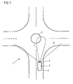
- Fig. 1 is a plan view and shows a roundabout 1 with a total of four driveways, a circular lane 2 and a central island 3.
- a Has device for adaptive speed and distance control By means of a schematically illustrated laser scanner 6, an area 7 is detected in front of the motor vehicle 1.
- an optionally present preceding vehicle can be detected.
- the device for adaptive speed and distance control is designed so that in the case of a preceding vehicle, the distance between the motor vehicle 5 and the preceding vehicle is controlled.
- the device intervenes in an engine control, a transmission control and a brake system control of the motor vehicle 5.
- the driver may set a desired speed on the adaptive cruise and cruise control device, and the device will then attempt to maintain this desired speed.
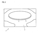
- Fig. 2 is a representation of a roundabout, which is in the direction of travel in front of the motor vehicle when it approaches the roundabout.
- the in Fig. 2 shown roundabout 1 has certain striking geometric shapes.
- each roundabout comprises the central island 3, which has an edge 10 which forms a boundary between the central island 3 and the circular carriageway 2.
- This edge 10 thus serves as a geometric parameter that can be detected by an evaluation of the acquired data created by the laser scanner 6.
- the extraction of such a geometric parameter from the data is done by means of a special algorithm.
- the detection of the central island 3 of the roundabout 1 takes place by detecting a geometric parameter, namely the edge 10, by analyzing the acquired data and comparing it with stored data or modeled data.
- the edges of central islands of a roundabout are characterized by a typical shape, the detection of such an edge thus the presence of a central island of a roundabout can be detected.
- the device for adaptive speed and distance control by the evaluation of the data of the laser scanner 6 After the device for adaptive speed and distance control by the evaluation of the data of the laser scanner 6 has detected the located on the trajectory in front of the motor vehicle 5 roundabout 1, it triggers an action to avoid a dangerous situation.
- a warning in the form of an optical and an acoustic signal is output to the driver.
- the driver is given the information that the control of the motor vehicle 5 is returned to him. Accordingly, the driver can even intervene in the control and press, for example, the brake.
- Fig. 3 is a similar representation as Fig. 1 and shows the motor vehicle 5 when entering the roundabout 1.
- the device for adaptive speed and distance control has previously checked whether there are 1 authorized vehicles in the roundabout. Since no such vehicles are present, the motor vehicle 5 can enter the circular lane 2. For this purpose, the device reduces the speed of the motor vehicle 5 by engaging in the braking system to a speed which allows the roundabout 1 to pass. Accordingly, the motor vehicle 5 passes the roundabout 1 under the control of the device without the driver having to intervene.
- Fig. 4 is a similar representation as Fig. 1 and Fig. 3 and shows a traffic situation in which a further motor vehicle 11 is located in the roundabout 1. Since this is already on the circular lane 2, it is entitled to travel. Accordingly, the action taken by the adaptive speed and distance control means in this case consists of braking the motor vehicle 5 to a stop before a stop line 12 of the roundabout 1. This triggered action is a consequence of the detection and detection of the roundabout 1, more specifically the detection of the center island 3 by means of the edge 10, with reference to Fig. 1 has been described.
- Fig. 5 is a schematic representation and shows the motor vehicle 5 and the essential components of an apparatus 13 for adaptive speed and distance control.
- the motor vehicle 5 has the arranged at the front of the motor vehicle 5 laser scanner 6, which is aligned to the front and thus objects, in particular a preceding vehicle or another road user, in front of the motor vehicle 5 can detect.
- the laser scanner 6 is coupled to an evaluation unit 14.
- the algorithm described is carried out in order to extract a geometric parameter, in particular an edge of the central island of a roundabout, from the data acquired by the laser scanner 6.
- the device 13 for adaptive speed and distance control is integrated in a driver assistance system with ACC function.
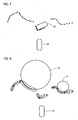
- Fig. 6 shows by way of example of the laser scanner 6 detected data
- the laser scanner 6 serves as a sensor for detecting the distance.
- the laser scanner data has noise, it is recognized that the punctiform laser scanner data has a certain structure.
- the point-shaped laser scanner data show the outer contour of a foreign vehicle 17.
- the laser scanner data of several horizontal scan planes are superimposed. Since the laser scanner detects the area in front of the motor vehicle in a plurality of horizontal and spaced scan planes, further information can be obtained by interpreting the various scan planes.
- Fig. 7 is a similar representation as Fig. 6 , wherein only a single horizontal scan plane, which was detected by the laser scanner 6, is shown.
- a motor vehicle 18 (ego vehicle) is shown.
- the laser scanner data corresponds to a set of points that can be interpreted as coordinates.
- the detected before the motor vehicle 18 Points correspond to the visible outer contour of a foreign vehicle 19. From the remaining points or the lines consisting of points, an algorithm extracts circular objects.
- Fig. 8 It is shown that the algorithm attempts to group together several points that might be on a circle segment. When a group of points has a certain size, the algorithm attempts to detect a circular object 20, 21. In the illustrated embodiment, the groups of points would fit two circular objects 20, 21. Then non-plausible objects are filtered out. These can be accessed either on a stored map, which is usually already present in a navigation device. Alternatively or additionally, information about the structure of roundabouts can be used. Typically, the motor vehicle 18 approaches a roundabout radially, slightly offset from the center, or the motor vehicle 18 drives a point between the center of the roundabout and its right end.
- the circular object 21 can not be the sought-after roundabout or the sought-after central island. Accordingly, the circular object 21 is not considered further. Thus remains - as in Fig. 9 is shown - only the circular object 20 left, which is identified as a central island of a lying in front of the motor vehicle 18 roundabout. Based on the radius or the diameter of the circular object 20 and the distance to the motor vehicle 18 can be set a suitable speed for entering the roundabout.
Landscapes
- Engineering & Computer Science (AREA)
- Mechanical Engineering (AREA)
- Transportation (AREA)
- Automation & Control Theory (AREA)
- Radar, Positioning & Navigation (AREA)
- Remote Sensing (AREA)
- Physics & Mathematics (AREA)
- Chemical & Material Sciences (AREA)
- Combustion & Propulsion (AREA)
- General Physics & Mathematics (AREA)
- Computer Networks & Wireless Communication (AREA)
- Electromagnetism (AREA)
- Human Computer Interaction (AREA)
- Mathematical Physics (AREA)
- Traffic Control Systems (AREA)
- Control Of Vehicle Engines Or Engines For Specific Uses (AREA)
- Controls For Constant Speed Travelling (AREA)
Abstract
Description
- Die Erfindung betrifft eine Einrichtung zur adaptiven Geschwindigkeits- und Abstandsregelung für ein Kraftfahrzeug, mit einem Sensor zum Erfassen des Abstands zu einem vorausfahrenden Fahrzeug, wobei die Einrichtung dazu ausgebildet ist, eine eingestellte Geschwindigkeit durch einen Eingriff in eine Motorsteuerung und/oder eine Getriebesteuerung und/oder eine Bremssystemsteuerung unter Berücksichtigung des erfassten Abstands zu regeln.
- Eine derartige Einrichtung ist ein Fahrerassistenzsystem, das auch als "Adaptive Cruise Control (ACC)" bezeichnet wird. Dabei wird mit einem Sensor der Abstand zu einem vorausfahrenden Fahrzeug gemessen und eine vom Fahrer vorgegebene Geschwindigkeit automatisch eingehalten, sofern dies bei Berücksichtigung der Straßenverhältnisse, des Verkehrs und gegebenenfalls weiterer Randbedingungen möglich ist. Zum vorausfahrenden Fahrzeug wird dabei durch das Fahrerassistenzsystem ein möglichst gleichbleibender Abstand eingehalten. Der Fahrer kann die Systemdynamik in mehreren Stufen einstellen bzw. anpassen. Bei eingeschalteter Adaptive Cruise Control ist nach wie vor der Fahrer für die Überwachung der Geschwindigkeit und des Abstands zum Vordermann verantwortlich, da das ACC nicht auf ortsfeste Objekte reagiert.
- Aus der
DE 10 2005 002 719 A1 ist ein Verfahren zur Kursprädiktion in Fahrerassistenzsystemen für Kraftfahrzeuge bekannt. Bei diesem Verfahren werden unterschiedliche Umfeldinformationen mittels Sensoren erfasst und als Rohdaten berücksichtigt, die aus Linienabschnitten zusammengesetzt sind, wobei ein Linienabschnitt durch ein Polynom repräsentiert wird. - Die
DE 10 2006 030 178 A1 schlägt ein Verfahren vor, das zum Erkennen von Bodenschwellen geeignet ist. Dabei wird ein optischer Sensor eingesetzt, aufgenommene Bilddaten werden einem Bildverarbeitungsalgorithmus erzogen, um zu ermitteln, ob es sich bei einem erfassten Objekt um eine Bodenschwelle handelt oder nicht. - Aus der
DE 10 2013 217 430 A1 ist ein Fahrerassistenzsystem für ein Kraftfahrzeug bekannt, bei dem mittels Sensoren Objekte vor dem Fahrzeug und seitlich davon erfasst werden. Durch eine Auswertung wird ein Fahrweg für das Fahrzeug so ausgewählt, dass ein Konflikt mit den erfassten Objekten vermieden wird. - Obwohl sich Einrichtungen zur adaptiven Geschwindigkeit- und Abstandsregelung für ein Kraftfahrzeug, insbesondere ACC-Fahrerassistenzsysteme, bewährt haben, können unter ungünstigen Umständen gefährliche Situationen auftreten, da die Einrichtung bestimmte Objekte, die sich entlang des Fahrwegs befinden, nicht erkennen kann bzw. nicht darauf reagiert. Dazu zählt beispielsweise ein Kreisverkehr. Ein Kreisverkehr ist ein Verkehrsknotenpunkt mit einer Kreisfahrbahn und einer Mittelinsel. Verkehrsteilnehmer, die sich auf der Kreisfahrbahn befinden, haben Vorfahrt vor einfahrenden Verkehrsteilnehmern. Vor dem Einfahren in die Kreisfahrbahn des Kreisverkehrs muss sich ein Fahrer zunächst Gewissheit darüber verschaffen, ob er in den Kreisverkehr einfahren kann oder ob er sein Fahrzeug zunächst abbremsen muss, gegebenenfalls bis zum Stillstand, um vorfahrtberechtigte Fahrzeuge passieren zu lassen. Selbst wenn kein vorfahrtberechtigter Verkehr vorhanden ist, ist es zumeist erforderlich, die Geschwindigkeit des Fahrzeugs zu reduzieren, um in die Kreisfahrbahn des Kreisverkehrs einfahren zu können.
- Ein herkömmliches ACC, das heißt eine herkömmliche Einrichtung zur adaptiven Geschwindigkeits- und Abstandsregelung, reagiert jedoch nicht auf einen Kreisverkehr, der sich vor dem Fahrzeug befindet. Eine gefährliche Situation kann somit dann eintreten, wenn der Fahrer irrtümlicherweise davon ausgeht, dass das ACC den vor ihm liegenden Kreisverkehr berücksichtigen und entsprechend abbremsen wird.
- Der Erfindung liegt daher die Aufgabe zugrunde, eine Einrichtung zur adaptiven Geschwindigkeits- und Abstandsregelung anzugeben, die in der Lage ist, auf einen Kreisverkehr zu reagieren, der sich auf dem Fahrweg befindet.
- Zur Lösung dieser Aufgabe ist bei einer Einrichtung der eingangs genannten Art erfindungsgemäß vorgesehen, dass sie dazu ausgebildet ist, mittels des Sensors zum Erfassen des Abstands eine sich auf der Trajektorie vor dem Kraftfahrzeug befindende Mittelinsel eines Kreisverkehrs zu detektieren und eine Aktion zum Vermeiden einer gefährlichen Situation auszulösen.
- Anders als ein herkömmliches ACC-System ist die erfindungsgemäße Einrichtung in der Lage, einen sich vor dem Fahrzeug befindenden Kreisverkehr zu detektieren und eine Aktion auszulösen, durch die das Entstehen einer gefährlichen Situation verhindert wird. Insbesondere wird durch die erfindungsgemäße Einrichtung verhindert, dass eine gefährliche Situation dadurch entsteht, dass ein Fahrer den vor ihm liegenden Kreisverkehr ignoriert, da er davon ausgeht, dass die Einrichtung den Kreisverkehr berücksichtigt.
- Bei der erfindungsgemäßen Einrichtung kann es vorgesehen sein, dass die ausgelöste Aktion das Ausgeben einer Information oder einer Warnung an einen Fahrer umfasst. Durch die ausgegebene Information oder Warnung wird dem Fahrer vermittelt, dass eine gefährliche Situation droht, so dass der Fahrer eingreifen kann. Der Fahrer kann beispielsweise einen Bremsvorgang oder ein Lenkmanöver oder eine Kombination davon durchführen. Durch die ausgegebene Information oder Warnung wird dem Fahrer vermittelt, dass er selbst eingreifen muss, um eine ansonsten drohende gefährliche Situation zu vermeiden.
- Gemäß einer Weiterbildung der Erfindung kann es vorgesehen sein, dass die ausgelöste Aktion die Aufforderung an den Fahrer umfasst, die Steuerung des Kraftfahrzeugs zu übernehmen. Dadurch wird die Rollenverteilung bei der Steuerung des Fahrzeugs geändert und von dem Fahrerassistenzsystem wieder zurück an den Fahrer gegeben. Der Fahrer weiß dann, dass er ab sofort allein für die Steuerung des Fahrzeugs verantwortlich ist.
- Es liegt auch im Rahmen der Erfindung, dass die ausgelöste Aktion das Abbremsen des Kraftfahrzeugs auf eine ein Passieren des Kreisverkehrs ermöglichende Geschwindigkeit umfasst. Da beim Einfahren in den Kreisverkehr eine Rechtskurve zu fahren ist, kann durch die erfindungsgemäße Einrichtung ein Abbremsen des Kraftfahrzeugs auf eine dafür geeignete Geschwindigkeit ausgelöst werden. In Abhängigkeit von den örtlichen Verhältnissen, insbesondere in Abhängigkeit von Sichtverhältnissen, Straßenbreite sowie in Abhängigkeit vom Vorhandensein weiterer Fahrzeuge kann die Geschwindigkeit, auf die das Kraftfahrzeug abgebremst wird, unterschiedlich sein. Die Geschwindigkeit wird jeweils so niedrig gewählt, dass ein gefahrloses Einfahren in den Kreisverkehr möglich ist.
- Im Rahmen der Erfindung kann es auch vorgesehen sein, dass die ausgelöste Aktion das Abbremsen des Kraftfahrzeugs bis zum Stillstand vor oder an einer Haltelinie des Kreisverkehrs umfasst. Ein Abbremsen bis zum Stillstand ist insbesondere dann erforderlich, wenn sich vorfahrtberechtigte Kraftfahrzeuge auf der Kreisfahrbahn befinden.
- Eine besonders zuverlässige Erfassung des Abstands zu einem vorausfahrenden Verkehrsteilnehmer kann mittels eines Sensors erfolgen, der als Radarsensor oder als Lidarsensor oder als Laserscanner ausgebildet ist. Daneben kann auch eine Kombination von Sensoren vorgesehen sein.
- Die erfindungsgemäße Einrichtung kann so ausgebildet sein, dass das Detektieren der Mittelinsel des Kreisverkehrs das Erfassen wenigstens eines geometrischen Parameters und das Vergleichen des geometrischen Parameters mit gespeicherten Daten und/oder modellierten Daten umfasst. Dabei wird von der Tatsache Gebrauch gemacht, dass eine Mittelinsel typische geometrische Parameter aufweist, durch die sie charakterisiert und detektiert werden kann. Vorzugsweise kann eine kreissegmentförmige Kante einer Mittelinsel als derartiger geometrischer Parameter verwendet werden. Eine derartige kreissegmentförmige Kante dient somit als Erkennungszeichen einer Mittelinsel. Dabei ist es vorteilhaft, dass praktisch alle Mittelinseln von Kreisverkehren eine derartige kreissegmentförmige Kante aufweisen, die durch einen Algorithmus aus Daten, die von dem Sensor erfasst worden sind, extrahiert und somit detektiert werden kann. Auf diese Weise kann eine sich vor dem Fahrzeug befindende Mittelinsel eines Kreisverkehrs zuverlässig identifiziert und von anderen ortsfesten Objekten wie beispielsweise ein Bordstein, eine Leitplanke oder eine Verkehrsinsel unterschieden werden. Die Auswertung zum Detektieren einer Kante einer Mittelinsel erfolgt mittels eines speziellen Algorithmus'.
- Daneben betrifft die Erfindung ein Kraftfahrzeug. Das erfindungsgemäße Kraftfahrzeug weist eine Einrichtung der beschriebenen Art auf.
- Daneben betrifft die Erfindung ein Verfahren für den Betrieb einer Einrichtung zur adaptiven Geschwindigkeits- und Abstandsregelung für ein Kraftfahrzeug, mit einem Sensor zum Erfassen des Abstands zu einem vorausfahrenden Fahrzeug, wobei die Einrichtung eine eingestellte Geschwindigkeit durch einen Eingriff in eine Motorsteuerung und/oder eine Getriebesteuerung und/oder eine Bremssystemsteuerung unter Berücksichtigung des erfassten Abstands regelt. Das erfindungsgemäße Verfahren zeichnet sich dadurch aus, dass die Einrichtung mittels des Sensors zum Erfassen des Abstands eine sich auf der Trajektorie vor dem Kraftfahrzeug befindende Mittelinsel eines Kreisverkehrs detektiert und eine Aktion zum Vermeiden einer gefährlichen Situation auslöst.
- Bei dem erfindungsgemäßen Verfahren wird es bevorzugt, dass zum Detektieren der Mittelinsel des Kreisverkehrs wenigstens ein geometrischer Parameter durch Auswerten von Sensordaten erfasst und mit gespeicherten Daten und/oder modellierten Daten verglichen wird.
- Vorzugsweise wird bei dem erfindungsgemäßen Verfahren eine kreissegmentförmige Kante einer Mittelinsel als geometrischer Parameter verwendet.
- Die Erfindung wird nachfolgend anhand von Ausführungsbeispielen unter Bezugnahme auf die Zeichnungen erläutert. Die Zeichnungen sind schematische Darstellungen und zeigen:
- Fig. 1
- eine Verkehrssituation, bei der die erfindungsgemäße Einrichtung eingesetzt wird;
- Fig. 2
- eine Darstellung eines Bereichs vor dem Kraftfahrzeug;
- Fig. 3
- eine weitere Verkehrssituation, bei der die erfindungsgemäße Einrichtung eingesetzt wird;
- Fig. 4
- eine weitere Verkehrssituation, bei der die erfindungsgemäße Einrichtung eingesetzt wird;
- Fig. 5
- ein Kraftfahrzeug mit einer erfindungsgemäßen Einrichtung;
- Fig. 6
- eine Draufsicht von punktförmigen Laserscannerdaten im Bereich der Mittelsinsel eines Kreisverkehrs;
- Fig. 7
- Laserscannerdaten einer einzigen horizontalen Kennebene eines Laserscanners;
- Fig. 8
- die in
Fig. 7 gezeigten Laserscannerdaten mit extrahierten kreisförmigen Objekten; und - Fig. 9
- der durch einen Algorithmus identifizierte Kreisverkehr.
-
Fig. 1 ist eine Draufsicht und zeigt einen Kreisverkehr 1 mit insgesamt vier Einfahrten, einer Kreisfahrbahn 2 und einer Mittelinsel 3. Auf einer Fahrbahn 4, die zum Kreisverkehr 1 führt, befindet sich ein Kraftfahrzeug 5, das eine Einrichtung zur adaptiven Geschwindigkeits- und Abstandsregelung aufweist. Mittels eines schematisch dargestellten Laserscanner 6 wird ein Bereich 7 vor dem Kraftfahrzeug 1 erfasst. Mittels des Laserscanners 6 kann ein gegebenenfalls vorhandenes, vorausfahrendes Fahrzeug erfasst werden. Die Einrichtung zur adaptiven Geschwindigkeits- und Abstandsregelung ist so ausgebildet, dass im Falle eines vorausfahrenden Fahrzeugs der Abstand zwischen dem Kraftfahrzeug 5 und dem vorausfahrenden Fahrzeug geregelt wird. Dazu greift die Einrichtung in eine Motorsteuerung, eine Getriebesteuerung und eine Bremssystemsteuerung des Kraftfahrzeugs 5 ein. Der Fahrer kann an der Einrichtung zur adaptiven Geschwindigkeits- und Abstandsregelung eine gewünschte Geschwindigkeit einstellen, die Einrichtung versucht dann, diese gewünschte Geschwindigkeit einzuhalten. Bei einem detektierten vorausfahrenden Fahrzeug ist es jedoch unter Umständen erforderlich, die aktuelle Geschwindigkeit auf eine niedrigere Geschwindigkeit als die eingestellte, gewünschte Geschwindigkeit zu verringern. -
Fig. 2 ist eine Darstellung eines Kreisverkehrs, der sich in Fahrtrichtung vor dem Kraftfahrzeug befindet, wenn es sich dem Kreisverkehr nähert. Der inFig. 2 gezeigte Kreisverkehr 1 weist bestimmte markante geometrische Formen auf. Insbesondere umfasst jeder Kreisverkehr die Mittelinsel 3, die eine Kante 10 aufweist, die eine Grenze zwischen der Mittelinsel 3 und der Kreisfahrbahn 2 bildet. Diese Kante 10 dient somit als geometrischer Parameter, der durch eine Auswertung der von dem Laserscanner 6 erstellten erfassten Daten detektiert werden kann. Das Extrahieren eines derartigen geometrischen Parameters aus den Daten erfolgt mittels eines speziellen Algorithmus. Das Detektieren der Mittelinsel 3 des Kreisverkehrs 1 erfolgt, indem durch Auswerten der erfassten Daten ein geometrischer Parameter, nämlich die Kante 10, erfasst und mit gespeicherten Daten oder modellierten Daten verglichen wird. Kanten von Mittelinseln eines Kreisverkehrs zeichnen sich durch eine typische Form aus, durch die Erkennung einer derartigen Kante kann somit das Vorhandensein einer Mittelinsel eines Kreisverkehrs detektiert werden. - Nachdem die Einrichtung zur adaptiven Geschwindigkeits- und Abstandsregelung durch die Auswertung der Daten des Laserscanners 6 den sich auf der Trajektorie vor dem Kraftfahrzeug 5 befindenden Kreisverkehr 1 detektiert hat, löst sie eine Aktion aus, um eine gefährliche Situation zu vermeiden.
- In dem dargestellten Ausführungsbeispiel wird eine Warnung in Form eines optischen und eines akustischen Signals an den Fahrer ausgegeben. Durch diese Warnung wird dem Fahrer die Information vermittelt, dass die Steuerung des Kraftfahrzeugs 5 wieder an ihn übergeben wird. Dementsprechend kann der Fahrer selbst in die Steuerung eingreifen und beispielsweise die Bremse betätigen.
-
Fig. 3 ist eine ähnliche Darstellung wieFig. 1 und zeigt das Kraftfahrzeug 5 beim Einfahren in den Kreisverkehr 1. Die Einrichtung zur adaptiven Geschwindigkeits- und Abstandsregelung hat zuvor geprüft, ob sich im Kreisverkehr 1 vorfahrtberechtigte Fahrzeuge befinden. Da keine derartigen Fahrzeuge vorhanden sind, kann das Kraftfahrzeug 5 in die Kreisfahrbahn 2 einfahren. Die Einrichtung reduziert dazu die Geschwindigkeit des Kraftfahrzeugs 5 durch einen Eingriff in das Bremssystem auf eine Geschwindigkeit, die ein Passieren des Kreisverkehrs 1 ermöglicht. Dementsprechend passiert das Kraftfahrzeug 5 den Kreisverkehr 1 unter der Steuerung der Einrichtung, ohne dass der Fahrer eingreifen muss. -
Fig. 4 ist eine ähnliche Darstellung wieFig. 1 undFig. 3 und zeigt eine Verkehrssituation, bei der sich im Kreisverkehr 1 ein weiteres Kraftfahrzeug 11 befindet. Da sich dieses bereits auf der Kreisfahrbahn 2 befindet, ist es bevorfahrtberechtigt. Dementsprechend besteht die von der Einrichtung zur adaptiven Geschwindigkeits- und Abstandsregelung durchgeführte Aktion in diesem Fall aus einem Abbremsen des Kraftfahrzeugs 5 bis zum Stillstand vor einer Haltelinie 12 des Kreisverkehrs 1. Diese ausgelöste Aktion ist eine Folge der Detektion und Erkennung des Kreisverkehrs 1, genauer gesagt der Erkennung der Mittelinsel 3 anhand der Kante 10, die unter Bezugnahme aufFig. 1 beschrieben wurde. -
Fig. 5 ist eine schematische Darstellung und zeigt das Kraftfahrzeug 5 sowie die wesentlichen Komponenten einer Einrichtung 13 zur adaptiven Geschwindigkeits- und Abstandsregelung. - Das Kraftfahrzeug 5 weist den an der Front des Kraftfahrzeugs 5 angeordneten Laserscanner 6 auf, der nach vorne ausgerichtet ist und somit Objekte, insbesondere ein vorausfahrendes Fahrzeug oder einen anderen Verkehrsteilnehmer, vor dem Kraftfahrzeug 5 erfassen kann. Der Laserscanner 6 ist mit einer Auswertungseinheit 14 gekoppelt. In der Auswertungseinheit 14 wird der beschriebene Algorithmus durchgeführt, um einen geometrischen Parameter, insbesondere eine Kante der Mittelinsel eines Kreisverkehrs aus den von dem Laserscanner 6 erfassten Daten zu extrahieren.
- Die Einrichtung 13 zur adaptiven Geschwindigkeits- und Abstandsregelung ist in ein Fahrerassistenzsystem mit ACC-Funktion integriert.
-
Fig. 6 zeigt beispielhaft von dem Laserscanner 6 erfasste Daten, der Laserscanner 6 dient dabei als Sensor zum Erfassen des Abstands. Obwohl die Laserscannerdaten Rauschen aufweisen, erkennt man, dass die punktförmigen Laserscannerdaten eine gewisse Struktur aufweisen. In der Draufsicht vonFig. 6 erkennt man mehrere Kreissegmente 15, 16 und somit die Position der Mittelinsel des Kreisverkehrs. Zusätzlich zeigen die punktförmigen Laserscannerdaten die Außenkontur eines Fremdfahrzeugs 17. InFig. 6 sind die Laserscannerdaten mehrerer horizontaler Scanebenen überlagert dargestellt. Da der Laserscanner den Bereich vor dem Kraftfahrzeug in mehreren horizontalen und voneinander beabstandeten Scanebenen erfasst, können durch die Interpretation der verschiedenen Scanebenen weitere Informationen gewonnen werden. -
Fig. 7 ist eine ähnliche Darstellung wieFig. 6 , wobei lediglich eine einzige horizontale Scanebene, die von dem Laserscanner 6 erfasst wurde, dargestellt ist. Zusätzlich ist ein Kraftfahrzeug 18 (Egofahrzeug) dargestellt. Die Laserscannerdaten entsprechen einer Menge von Punkten, die als Koordinaten interpretiert werden können. Die vor dem Kraftfahrzeug 18 erfassten Punkte entsprechen der sichtbaren Außenkontur eines Fremdfahrzeugs 19. Aus den übrigen Punkten beziehungsweise den aus Punkten bestehenden Linien extrahiert ein Algorithmus kreisförmige Objekte. - In
Fig. 8 ist dargestellt, dass der Algorithmus versucht, mehrere Punkte, die sich auf einem Kreissegment befinden könnten, zu einer Gruppe zusammenzufassen. Wenn eine Gruppe von Punkten eine gewisse Größe aufweist, versucht der Algorithmus ein kreisförmiges Objekt 20, 21 zu erkennen. In dem dargestellten Ausführungsbeispiel würden die Gruppen von Punkten zu zwei kreisförmigen Objekten 20, 21 passen. Anschließend werden nicht plausible Objekte herausgefiltert. Dazu kann entweder auf eine gespeicherte Karte zurückgegriffen werden, die zumeist ohnehin schon in einem Navigationsgerät vorhanden ist. Alternativ oder zusätzlich können auch Informationen über den Aufbau von Kreisverkehren herangezogen werden. Typischerweise nähert sich das Kraftfahrzeug 18 einem Kreisverkehr radial, etwas versetzt vom Mittelpunkt beziehungsweise das Kraftfahrzeug 18 steuert einen Punkt zwischen dem Mittelpunkt des Kreisverkehrs und dessen rechtem Ende an. Somit ist für die Einrichtung erkennbar, dass das kreisförmige Objekt 21 nicht der gesuchte Kreisverkehr beziehungsweise die gesuchte Mittelinsel sein kann. Dementsprechend wird das kreisförmige Objekt 21 nicht weiter berücksichtigt. Somit bleibt - wie inFig. 9 gezeigt ist - lediglich das kreisförmige Objekt 20 übrig, das als Mittelinsel eines vor dem Kraftfahrzeug 18 liegenden Kreisverkehrs identifiziert wird. Anhand des Radius beziehungsweise des Durchmessers des kreisförmigen Objekts 20 und dem Abstand zum Kraftfahrzeug 18 kann eine passende Geschwindigkeit für das Einfahren in den Kreisverkehr festgelegt werden.
Claims (12)
- Einrichtung (13) zur adaptiven Geschwindigkeits- und Abstandsregelung für ein Kraftfahrzeug (5), mit einem Sensor zum Erfassen des Abstands zu einem vorausfahrenden Fahrzeug, wobei die Einrichtung (13) dazu ausgebildet ist, eine eingestellte Geschwindigkeit durch einen Eingriff in eine Motorsteuerung und/oder eine Getriebesteuerung und/oder eine Bremssystemsteuerung unter Berücksichtigung des erfassten Abstands zu regeln, wobei die Einrichtung (13) dazu ausgebildet ist, mittels des Sensors zum Erfassen des Abstands eine sich auf der Trajektorie vor dem Kraftfahrzeug (5) befindende Mittelinsel (3) eines Kreisverkehrs (1) zu detektieren und eine Aktion zum Vermeiden einer gefährlichen Situation auszulösen,
dadurch gekennzeichnet,
dass die Einrichtung (13) einen Algorithmus aufweist, der dazu ausgebildet ist, eine Kante der Mittelinsel (3) des Kreisverkehrs (1) zu detektieren, indem mehrere von dem Laserscanner (6) erfasste Punkte einer einzigen horizontalen Scanebene zu einer Gruppe zusammengefasst werden, um ein kreisförmiges Objekt (20, 21) zu erkennen. - Einrichtung nach Anspruch 1,
dadurch gekennzeichnet,
dass die ausgelöste Aktion das Ausgeben einer Information oder einer Warnung an einen Fahrer umfasst. - Einrichtung nach Anspruch 1 oder 2,
dadurch gekennzeichnet,
dass die ausgelöste Aktion die Aufforderung an einen Fahrer umfasst, die Steuerung des Kraftfahrzeugs (5) zu übernehmen. - Einrichtung nach einem der vorangehenden Ansprüche,
dadurch gekennzeichnet,
dass die ausgelöste Aktion das Abbremsen des Kraftfahrzeugs (5) auf eine ein Passieren des Kreisverkehrs (1) ermöglichende Geschwindigkeit umfasst. - Einrichtung nach einem der vorangehenden Ansprüche,
dadurch gekennzeichnet,
dass die ausgelöste Aktion das Abbremsen des Kraftfahrzeugs (5) bis zum Stillstand vor oder an einer Haltelinie (12) des Kreisverkehrs (1) umfasst. - Einrichtung nach einem der vorangehenden Ansprüche,
dadurch gekennzeichnet,
dass der Sensor zum Erfassen des Abstands als Radarsensor (6) oder als Lidarsensor oder Laserscanner oder als Kombination von Sensoren ausgebildet ist. - Einrichtung nach einem der vorangehenden Ansprüche,
dadurch gekennzeichnet,
dass das Detektieren der Mittelinsel (3) des Kreisverkehrs (1) das Erfassen wenigstens eines geometrischen Parameters und das Vergleichen des geometrischen Parameters mit gespeicherten Daten und/oder modellierten Daten umfasst. - Einrichtung nach Anspruch 7,
dadurch gekennzeichnet, dass ein geometrischer Parameter eine kreissegmentförmige Kante (10) einer Mittelinsel (3) ist. - Kraftfahrzeug (5), umfassend eine Einrichtung (13) nach einem der Ansprüche 1 bis 8.
- Verfahren für den Betrieb einer Einrichtung (13) zur adaptiven Geschwindigkeits- und Abstandsregelung für ein Kraftfahrzeug (5), mit einem Sensor zum Erfassen des Abstands zu einem vorausfahrenden Fahrzeug, wobei die Einrichtung (13) eine eingestellte Geschwindigkeit durch einen Eingriff in eine Motorsteuerung und/oder eine Getriebesteuerung und/oder eine Bremssystemsteuerung unter Berücksichtigung des erfassten Abstands regelt, wobei
die Einrichtung (13) mittels des Sensors zum Erfassen des Abstands eine sich auf der Trajektorie vor dem Kraftfahrzeug (5) befindende Mittelinsel (3) eines Kreisverkehrs (1) detektiert und eine Aktion zum Vermeiden einer gefährlichen Situation auslöst,
dadurch gekennzeichnet,
dass die Einrichtung (13) einen Algorithmus aufweist, der eine Kante der Mittelinsel (3) des Kreisverkehrs (1) detektiert, indem mehrere von dem Laserscanner (6) erfasste Punkte einer einzigen horizontalen Scanebene zu einer Gruppe zusammengefasst werden, um ein kreisförmiges Objekt (20, 21) zu erkennen. - Verfahren nach Anspruch 10,
dadurch gekennzeichnet,
dass zum Detektieren der Mittelinsel (3) des Kreisverkehrs (1) wenigstens ein geometrischer Parameter durch Auswerten von durch den Sensor erfasster Daten detektiert und mit gespeicherten Daten und/oder modellierten Daten verglichen wird. - Verfahren nach Anspruch 11,
dadurch gekennzeichnet,
dass eine kreissegmentförmige Kante (10) einer Mittelinsel (3) als geometrischer Parameter verwendet wird.
Applications Claiming Priority (1)
| Application Number | Priority Date | Filing Date | Title |
|---|---|---|---|
| DE102014016578.7A DE102014016578A1 (de) | 2014-11-08 | 2014-11-08 | Einrichtung zur adaptiven Geschwindigkeits- und Abstandsregelung für ein Kraftfahrzeug, zugehöriges Kraftfahrzeug und zugehöriges Verfahren |
Publications (3)
| Publication Number | Publication Date |
|---|---|
| EP3018031A2 true EP3018031A2 (de) | 2016-05-11 |
| EP3018031A3 EP3018031A3 (de) | 2016-07-13 |
| EP3018031B1 EP3018031B1 (de) | 2021-03-17 |
Family
ID=54364955
Family Applications (1)
| Application Number | Title | Priority Date | Filing Date |
|---|---|---|---|
| EP15003099.7A Not-in-force EP3018031B1 (de) | 2014-11-08 | 2015-10-29 | Einrichtung zur adaptiven geschwindigkeits- und abstandsregelung für ein kraftfahrzeug, zugehöriges kraftfahrzeug und zugehöriges verfahren |
Country Status (2)
| Country | Link |
|---|---|
| EP (1) | EP3018031B1 (de) |
| DE (1) | DE102014016578A1 (de) |
Cited By (11)
| Publication number | Priority date | Publication date | Assignee | Title |
|---|---|---|---|---|
| CN113677585A (zh) * | 2021-06-22 | 2021-11-19 | 华为技术有限公司 | 一种盲区检测方法和装置 |
| WO2022078853A1 (de) * | 2020-10-12 | 2022-04-21 | Bayerische Motoren Werke Aktiengesellschaft | Fahrzeugführungssystem und verfahren zum betreiben einer fahrfunktion bei vorliegen eines widerspruchs mit kartendaten |
| FR3136432A1 (fr) * | 2022-06-14 | 2023-12-15 | Psa Automobiles Sa | Méthodes et systèmes d’aide à la conduite d’un véhicule automobile à l’approche d’une intersection avec priorité |
| US12397808B2 (en) | 2020-10-12 | 2025-08-26 | Bayerische Motoren Werke Aktiengesellschaft | Vehicle control system and method for operating a driving function upon actuation of the accelerator pedal |
| US12415517B2 (en) | 2020-10-12 | 2025-09-16 | Bayerische Motoren Werke Aktiengesellschaft | Vehicle guidance system and method for automated starting of a vehicle |
| US12479458B2 (en) | 2020-10-12 | 2025-11-25 | Bayerische Motoren Werke Aktiengesellschaft | Vehicle control system and method for outputting information related to a signaling unit |
| US12491904B2 (en) | 2020-10-12 | 2025-12-09 | Bayerische Motoren Werke Aktiengesellschaft | Vehicle guidance system and method for operating a driving function in different modes |
| US12509084B2 (en) | 2020-10-12 | 2025-12-30 | Bayerische Motoren Werke Aktiengesellschaft | Vehicle control system and method for operating a driving function according to a preceding vehicle |
| US12528470B2 (en) | 2020-10-12 | 2026-01-20 | Bayerische Motoren Werke Aktiengesellschaft | Vehicle guidance system and method for operating a driving function following a driving-off process |
| US12534081B2 (en) | 2020-10-12 | 2026-01-27 | Bayerische Motoren Werke Aktiengesellschaft | Vehicle control system and method for operating a driving function taking into account the distance from the stop line |
| US12570287B2 (en) | 2020-10-12 | 2026-03-10 | Bayerische Motoren Werke Aktiengesellschaft | Vehicle guidance system and method for operating a travel function on the basis of the distance from a signaling unit |
Families Citing this family (4)
| Publication number | Priority date | Publication date | Assignee | Title |
|---|---|---|---|---|
| FR3056530B1 (fr) * | 2016-09-29 | 2019-07-12 | Valeo Schalter Und Sensoren Gmbh | Detection d'obstacles par fusion d'objets pour vehicule automobile |
| FR3056531B1 (fr) * | 2016-09-29 | 2019-07-12 | Valeo Schalter Und Sensoren Gmbh | Detection d'obstacles pour vehicule automobile |
| DE102017201048A1 (de) | 2017-01-24 | 2018-07-26 | Zf Friedrichshafen Ag | Verfahren zur Regelung des Verkehrsflusses in einem Kreisverkehr |
| FR3110886B1 (fr) * | 2020-06-02 | 2024-10-04 | Renault Sas | Procédé et système de contrôle de la vitesse d’un véhicule. |
Citations (3)
| Publication number | Priority date | Publication date | Assignee | Title |
|---|---|---|---|---|
| DE102005002719A1 (de) | 2005-01-20 | 2006-08-03 | Robert Bosch Gmbh | Verfahren zur Kursprädiktion in Fahrerassistenzsystemen für Kraftfahrzeuge |
| DE102006030178A1 (de) | 2006-06-30 | 2008-01-03 | Robert Bosch Gmbh | Verfahren und System zur Unterstützung des Fahrers eines Kraftfahrzeugs bei der Erkennung von Bodenschwellen |
| DE102013217430A1 (de) | 2012-09-04 | 2014-03-06 | Magna Electronics, Inc. | Fahrerassistenzsystem für ein Kraftfahrzeug |
Family Cites Families (4)
| Publication number | Priority date | Publication date | Assignee | Title |
|---|---|---|---|---|
| US5455669A (en) * | 1992-12-08 | 1995-10-03 | Erwin Sick Gmbh Optik-Elektronik | Laser range finding apparatus |
| DE102004005229A1 (de) * | 2004-02-03 | 2005-08-18 | Robert Bosch Gmbh | Abstandsregelsystem für Kraftfahrzeuge |
| DE102007036417A1 (de) * | 2007-08-02 | 2009-02-05 | Daimler Ag | Verfahren zum Betreiben eines Abstandsregelsystems für Fahrzeuge |
| US8364334B2 (en) * | 2008-10-30 | 2013-01-29 | Honeywell International Inc. | System and method for navigating an autonomous vehicle using laser detection and ranging |
-
2014
- 2014-11-08 DE DE102014016578.7A patent/DE102014016578A1/de not_active Withdrawn
-
2015
- 2015-10-29 EP EP15003099.7A patent/EP3018031B1/de not_active Not-in-force
Patent Citations (3)
| Publication number | Priority date | Publication date | Assignee | Title |
|---|---|---|---|---|
| DE102005002719A1 (de) | 2005-01-20 | 2006-08-03 | Robert Bosch Gmbh | Verfahren zur Kursprädiktion in Fahrerassistenzsystemen für Kraftfahrzeuge |
| DE102006030178A1 (de) | 2006-06-30 | 2008-01-03 | Robert Bosch Gmbh | Verfahren und System zur Unterstützung des Fahrers eines Kraftfahrzeugs bei der Erkennung von Bodenschwellen |
| DE102013217430A1 (de) | 2012-09-04 | 2014-03-06 | Magna Electronics, Inc. | Fahrerassistenzsystem für ein Kraftfahrzeug |
Cited By (12)
| Publication number | Priority date | Publication date | Assignee | Title |
|---|---|---|---|---|
| WO2022078853A1 (de) * | 2020-10-12 | 2022-04-21 | Bayerische Motoren Werke Aktiengesellschaft | Fahrzeugführungssystem und verfahren zum betreiben einer fahrfunktion bei vorliegen eines widerspruchs mit kartendaten |
| US12397808B2 (en) | 2020-10-12 | 2025-08-26 | Bayerische Motoren Werke Aktiengesellschaft | Vehicle control system and method for operating a driving function upon actuation of the accelerator pedal |
| US12415517B2 (en) | 2020-10-12 | 2025-09-16 | Bayerische Motoren Werke Aktiengesellschaft | Vehicle guidance system and method for automated starting of a vehicle |
| US12479458B2 (en) | 2020-10-12 | 2025-11-25 | Bayerische Motoren Werke Aktiengesellschaft | Vehicle control system and method for outputting information related to a signaling unit |
| US12491904B2 (en) | 2020-10-12 | 2025-12-09 | Bayerische Motoren Werke Aktiengesellschaft | Vehicle guidance system and method for operating a driving function in different modes |
| US12509084B2 (en) | 2020-10-12 | 2025-12-30 | Bayerische Motoren Werke Aktiengesellschaft | Vehicle control system and method for operating a driving function according to a preceding vehicle |
| US12528470B2 (en) | 2020-10-12 | 2026-01-20 | Bayerische Motoren Werke Aktiengesellschaft | Vehicle guidance system and method for operating a driving function following a driving-off process |
| US12534081B2 (en) | 2020-10-12 | 2026-01-27 | Bayerische Motoren Werke Aktiengesellschaft | Vehicle control system and method for operating a driving function taking into account the distance from the stop line |
| US12545279B2 (en) | 2020-10-12 | 2026-02-10 | Bayerische Motoren Werke Aktiengesellschaft | Vehicle guidance system and method for operating a driving function in the presence of a contradiction with map data |
| US12570287B2 (en) | 2020-10-12 | 2026-03-10 | Bayerische Motoren Werke Aktiengesellschaft | Vehicle guidance system and method for operating a travel function on the basis of the distance from a signaling unit |
| CN113677585A (zh) * | 2021-06-22 | 2021-11-19 | 华为技术有限公司 | 一种盲区检测方法和装置 |
| FR3136432A1 (fr) * | 2022-06-14 | 2023-12-15 | Psa Automobiles Sa | Méthodes et systèmes d’aide à la conduite d’un véhicule automobile à l’approche d’une intersection avec priorité |
Also Published As
| Publication number | Publication date |
|---|---|
| EP3018031A3 (de) | 2016-07-13 |
| DE102014016578A1 (de) | 2016-05-12 |
| EP3018031B1 (de) | 2021-03-17 |
Similar Documents
| Publication | Publication Date | Title |
|---|---|---|
| EP3018031B1 (de) | Einrichtung zur adaptiven geschwindigkeits- und abstandsregelung für ein kraftfahrzeug, zugehöriges kraftfahrzeug und zugehöriges verfahren | |
| EP3253634B1 (de) | Verarbeiten von sensordaten für ein fahrerassistenzsystem | |
| EP2636577B1 (de) | Verfahren zum Warnen des Fahrers eines Kraftfahrzeugs vor einer sich anbahnenden Gefahrensituation infolge eines unbeabsichtigten Driftens auf eine Gegenverkehrsfahrspur | |
| EP2234864B1 (de) | Fahrerassistenzsystem und verfahren zur unterstützung des fahrers eines fahrzeugs beim halten einer durch fahrspurmarkierungen begrenzten fahrspur | |
| DE102016206317B9 (de) | Evakuierungsfahrassistenzvorrichtung | |
| DE102009007885B4 (de) | Verfahren zur Erkennung von auf die eigene Fahrspur einscherenden oder aus der eigenen Fahrspur ausscherenden Fahrzeugen | |
| DE102018009028A1 (de) | Unterstützungssystem für einen Notfall-Spurwechsel | |
| DE102011116822B4 (de) | Überwachungssystem zur Überwachung des Umfeldes von Fahrzeugen, insbesondere von Kraft- und/oder Nutzfahrzeugen | |
| DE102016011970A1 (de) | Fahrzeugsicherheitssystem | |
| EP3157793B1 (de) | Bestimmen eines zustands eines fahrzeugs und unterstützung eines fahrers beim führen des fahrzeugs | |
| DE102018203376A1 (de) | Verfahren zum Detektieren und Berücksichtigen eines irregulären Fahrverhaltens eines Zielfahrzeugs | |
| DE102009017152A1 (de) | Verfahren und Vorrichtung zur Längs- und Querführung eines Kraftfahrzeugs | |
| DE102014202385B4 (de) | Fahrerassistenzsystem für Kraftfahrzeuge mit einem Verfahren zur Erkennung eines Fahrerausweichwunsches | |
| DE102018009033A1 (de) | Autonome Unterstützung für Straßenauffahrt | |
| EP3095102A1 (de) | Verfahren und system zur erkennung einer rettungsgassensituation | |
| EP3105092B1 (de) | Verfahren zum betrieb eines zur wenigstens teilweise automatischen fahrzeugführung ausgebildeten fahrzeugsystems und kraftfahrzeug | |
| DE102016120876A1 (de) | Verfahren, System und Computerprogrammprodukt zur Erkennung eines möglichen Spurwechsels eines Fremdfahrzeugs, sowie Fahrzeug | |
| DE102018104104A1 (de) | Fahrerunterstützungsverfahren für ein Fahrzeug | |
| DE102009052773B3 (de) | Verfahren zum Betrieb eines Stauassistenzsystems | |
| WO2009127478A1 (de) | Verfahren zur überwachung eines verkehrswegs für ein verkehrsmittel einer vorbestimmten art | |
| DE102016201190A1 (de) | Wendeassistent | |
| EP3684645B1 (de) | Verkürzung von lichtführungsfunktionen | |
| EP3036727B1 (de) | Ortsfeste einrichtung zur verringerung der kollisionsgefahr von kraftfahrzeugen | |
| DE102015205930B4 (de) | Automatisches Führen eines Fahrzeugs | |
| DE102011011319A1 (de) | Verfahren zum Beurteilen der Fahreraufmerksamkeit |
Legal Events
| Date | Code | Title | Description |
|---|---|---|---|
| PUAI | Public reference made under article 153(3) epc to a published international application that has entered the european phase |
Free format text: ORIGINAL CODE: 0009012 |
|
| AK | Designated contracting states |
Kind code of ref document: A2 Designated state(s): AL AT BE BG CH CY CZ DE DK EE ES FI FR GB GR HR HU IE IS IT LI LT LU LV MC MK MT NL NO PL PT RO RS SE SI SK SM TR |
|
| AX | Request for extension of the european patent |
Extension state: BA ME |
|
| PUAL | Search report despatched |
Free format text: ORIGINAL CODE: 0009013 |
|
| AK | Designated contracting states |
Kind code of ref document: A3 Designated state(s): AL AT BE BG CH CY CZ DE DK EE ES FI FR GB GR HR HU IE IS IT LI LT LU LV MC MK MT NL NO PL PT RO RS SE SI SK SM TR |
|
| AX | Request for extension of the european patent |
Extension state: BA ME |
|
| RIC1 | Information provided on ipc code assigned before grant |
Ipc: B60W 30/14 20060101ALI20160607BHEP Ipc: G01S 17/93 20060101ALN20160607BHEP Ipc: B60W 30/16 20120101ALN20160607BHEP Ipc: G01S 13/86 20060101ALI20160607BHEP Ipc: B60T 7/22 20060101ALI20160607BHEP Ipc: B60W 10/184 20120101ALI20160607BHEP Ipc: B60W 10/10 20120101ALI20160607BHEP Ipc: B60W 30/18 20120101ALI20160607BHEP Ipc: B60W 30/09 20120101ALI20160607BHEP Ipc: B60W 40/06 20120101ALI20160607BHEP Ipc: B60W 50/14 20120101AFI20160607BHEP Ipc: G01S 7/481 20060101ALI20160607BHEP Ipc: B60W 10/04 20060101ALI20160607BHEP |
|
| STAA | Information on the status of an ep patent application or granted ep patent |
Free format text: STATUS: REQUEST FOR EXAMINATION WAS MADE |
|
| 17P | Request for examination filed |
Effective date: 20170113 |
|
| RBV | Designated contracting states (corrected) |
Designated state(s): AL AT BE BG CH CY CZ DE DK EE ES FI FR GB GR HR HU IE IS IT LI LT LU LV MC MK MT NL NO PL PT RO RS SE SI SK SM TR |
|
| STAA | Information on the status of an ep patent application or granted ep patent |
Free format text: STATUS: EXAMINATION IS IN PROGRESS |
|
| 17Q | First examination report despatched |
Effective date: 20180105 |
|
| GRAP | Despatch of communication of intention to grant a patent |
Free format text: ORIGINAL CODE: EPIDOSNIGR1 |
|
| STAA | Information on the status of an ep patent application or granted ep patent |
Free format text: STATUS: GRANT OF PATENT IS INTENDED |
|
| RIC1 | Information provided on ipc code assigned before grant |
Ipc: B60W 40/06 20120101ALI20201201BHEP Ipc: G01S 7/481 20060101ALI20201201BHEP Ipc: B60T 7/22 20060101ALI20201201BHEP Ipc: B60W 30/16 20200101ALN20201201BHEP Ipc: G01S 13/86 20060101ALI20201201BHEP Ipc: B60W 50/14 20200101AFI20201201BHEP Ipc: B60W 10/10 20120101ALI20201201BHEP Ipc: B60W 30/14 20060101ALI20201201BHEP Ipc: B60W 10/184 20120101ALI20201201BHEP Ipc: B60W 30/09 20120101ALI20201201BHEP Ipc: G01S 17/93 20200101ALN20201201BHEP Ipc: B60W 10/04 20060101ALI20201201BHEP Ipc: B60W 30/18 20120101ALI20201201BHEP |
|
| INTG | Intention to grant announced |
Effective date: 20201216 |
|
| GRAS | Grant fee paid |
Free format text: ORIGINAL CODE: EPIDOSNIGR3 |
|
| GRAA | (expected) grant |
Free format text: ORIGINAL CODE: 0009210 |
|
| STAA | Information on the status of an ep patent application or granted ep patent |
Free format text: STATUS: THE PATENT HAS BEEN GRANTED |
|
| AK | Designated contracting states |
Kind code of ref document: B1 Designated state(s): AL AT BE BG CH CY CZ DE DK EE ES FI FR GB GR HR HU IE IS IT LI LT LU LV MC MK MT NL NO PL PT RO RS SE SI SK SM TR |
|
| REG | Reference to a national code |
Ref country code: GB Ref legal event code: FG4D Free format text: NOT ENGLISH |
|
| REG | Reference to a national code |
Ref country code: CH Ref legal event code: EP |
|
| REG | Reference to a national code |
Ref country code: DE Ref legal event code: R096 Ref document number: 502015014399 Country of ref document: DE |
|
| REG | Reference to a national code |
Ref country code: IE Ref legal event code: FG4D Free format text: LANGUAGE OF EP DOCUMENT: GERMAN |
|
| REG | Reference to a national code |
Ref country code: AT Ref legal event code: REF Ref document number: 1371975 Country of ref document: AT Kind code of ref document: T Effective date: 20210415 |
|
| REG | Reference to a national code |
Ref country code: LT Ref legal event code: MG9D |
|
| PG25 | Lapsed in a contracting state [announced via postgrant information from national office to epo] |
Ref country code: GR Free format text: LAPSE BECAUSE OF FAILURE TO SUBMIT A TRANSLATION OF THE DESCRIPTION OR TO PAY THE FEE WITHIN THE PRESCRIBED TIME-LIMIT Effective date: 20210618 Ref country code: FI Free format text: LAPSE BECAUSE OF FAILURE TO SUBMIT A TRANSLATION OF THE DESCRIPTION OR TO PAY THE FEE WITHIN THE PRESCRIBED TIME-LIMIT Effective date: 20210317 Ref country code: HR Free format text: LAPSE BECAUSE OF FAILURE TO SUBMIT A TRANSLATION OF THE DESCRIPTION OR TO PAY THE FEE WITHIN THE PRESCRIBED TIME-LIMIT Effective date: 20210317 Ref country code: BG Free format text: LAPSE BECAUSE OF FAILURE TO SUBMIT A TRANSLATION OF THE DESCRIPTION OR TO PAY THE FEE WITHIN THE PRESCRIBED TIME-LIMIT Effective date: 20210617 Ref country code: NO Free format text: LAPSE BECAUSE OF FAILURE TO SUBMIT A TRANSLATION OF THE DESCRIPTION OR TO PAY THE FEE WITHIN THE PRESCRIBED TIME-LIMIT Effective date: 20210617 |
|
| REG | Reference to a national code |
Ref country code: NL Ref legal event code: MP Effective date: 20210317 |
|
| PG25 | Lapsed in a contracting state [announced via postgrant information from national office to epo] |
Ref country code: SE Free format text: LAPSE BECAUSE OF FAILURE TO SUBMIT A TRANSLATION OF THE DESCRIPTION OR TO PAY THE FEE WITHIN THE PRESCRIBED TIME-LIMIT Effective date: 20210317 Ref country code: RS Free format text: LAPSE BECAUSE OF FAILURE TO SUBMIT A TRANSLATION OF THE DESCRIPTION OR TO PAY THE FEE WITHIN THE PRESCRIBED TIME-LIMIT Effective date: 20210317 Ref country code: LV Free format text: LAPSE BECAUSE OF FAILURE TO SUBMIT A TRANSLATION OF THE DESCRIPTION OR TO PAY THE FEE WITHIN THE PRESCRIBED TIME-LIMIT Effective date: 20210317 |
|
| PG25 | Lapsed in a contracting state [announced via postgrant information from national office to epo] |
Ref country code: NL Free format text: LAPSE BECAUSE OF FAILURE TO SUBMIT A TRANSLATION OF THE DESCRIPTION OR TO PAY THE FEE WITHIN THE PRESCRIBED TIME-LIMIT Effective date: 20210317 |
|
| PG25 | Lapsed in a contracting state [announced via postgrant information from national office to epo] |
Ref country code: SM Free format text: LAPSE BECAUSE OF FAILURE TO SUBMIT A TRANSLATION OF THE DESCRIPTION OR TO PAY THE FEE WITHIN THE PRESCRIBED TIME-LIMIT Effective date: 20210317 Ref country code: EE Free format text: LAPSE BECAUSE OF FAILURE TO SUBMIT A TRANSLATION OF THE DESCRIPTION OR TO PAY THE FEE WITHIN THE PRESCRIBED TIME-LIMIT Effective date: 20210317 Ref country code: CZ Free format text: LAPSE BECAUSE OF FAILURE TO SUBMIT A TRANSLATION OF THE DESCRIPTION OR TO PAY THE FEE WITHIN THE PRESCRIBED TIME-LIMIT Effective date: 20210317 Ref country code: LT Free format text: LAPSE BECAUSE OF FAILURE TO SUBMIT A TRANSLATION OF THE DESCRIPTION OR TO PAY THE FEE WITHIN THE PRESCRIBED TIME-LIMIT Effective date: 20210317 |
|
| PG25 | Lapsed in a contracting state [announced via postgrant information from national office to epo] |
Ref country code: IS Free format text: LAPSE BECAUSE OF FAILURE TO SUBMIT A TRANSLATION OF THE DESCRIPTION OR TO PAY THE FEE WITHIN THE PRESCRIBED TIME-LIMIT Effective date: 20210717 Ref country code: PT Free format text: LAPSE BECAUSE OF FAILURE TO SUBMIT A TRANSLATION OF THE DESCRIPTION OR TO PAY THE FEE WITHIN THE PRESCRIBED TIME-LIMIT Effective date: 20210719 Ref country code: PL Free format text: LAPSE BECAUSE OF FAILURE TO SUBMIT A TRANSLATION OF THE DESCRIPTION OR TO PAY THE FEE WITHIN THE PRESCRIBED TIME-LIMIT Effective date: 20210317 Ref country code: ES Free format text: LAPSE BECAUSE OF FAILURE TO SUBMIT A TRANSLATION OF THE DESCRIPTION OR TO PAY THE FEE WITHIN THE PRESCRIBED TIME-LIMIT Effective date: 20210317 Ref country code: SK Free format text: LAPSE BECAUSE OF FAILURE TO SUBMIT A TRANSLATION OF THE DESCRIPTION OR TO PAY THE FEE WITHIN THE PRESCRIBED TIME-LIMIT Effective date: 20210317 Ref country code: RO Free format text: LAPSE BECAUSE OF FAILURE TO SUBMIT A TRANSLATION OF THE DESCRIPTION OR TO PAY THE FEE WITHIN THE PRESCRIBED TIME-LIMIT Effective date: 20210317 |
|
| REG | Reference to a national code |
Ref country code: DE Ref legal event code: R097 Ref document number: 502015014399 Country of ref document: DE |
|
| PLBE | No opposition filed within time limit |
Free format text: ORIGINAL CODE: 0009261 |
|
| STAA | Information on the status of an ep patent application or granted ep patent |
Free format text: STATUS: NO OPPOSITION FILED WITHIN TIME LIMIT |
|
| PG25 | Lapsed in a contracting state [announced via postgrant information from national office to epo] |
Ref country code: AL Free format text: LAPSE BECAUSE OF FAILURE TO SUBMIT A TRANSLATION OF THE DESCRIPTION OR TO PAY THE FEE WITHIN THE PRESCRIBED TIME-LIMIT Effective date: 20210317 Ref country code: DK Free format text: LAPSE BECAUSE OF FAILURE TO SUBMIT A TRANSLATION OF THE DESCRIPTION OR TO PAY THE FEE WITHIN THE PRESCRIBED TIME-LIMIT Effective date: 20210317 |
|
| 26N | No opposition filed |
Effective date: 20211220 |
|
| PG25 | Lapsed in a contracting state [announced via postgrant information from national office to epo] |
Ref country code: SI Free format text: LAPSE BECAUSE OF FAILURE TO SUBMIT A TRANSLATION OF THE DESCRIPTION OR TO PAY THE FEE WITHIN THE PRESCRIBED TIME-LIMIT Effective date: 20210317 |
|
| PG25 | Lapsed in a contracting state [announced via postgrant information from national office to epo] |
Ref country code: IT Free format text: LAPSE BECAUSE OF FAILURE TO SUBMIT A TRANSLATION OF THE DESCRIPTION OR TO PAY THE FEE WITHIN THE PRESCRIBED TIME-LIMIT Effective date: 20210317 |
|
| REG | Reference to a national code |
Ref country code: CH Ref legal event code: PL |
|
| PG25 | Lapsed in a contracting state [announced via postgrant information from national office to epo] |
Ref country code: IS Free format text: LAPSE BECAUSE OF FAILURE TO SUBMIT A TRANSLATION OF THE DESCRIPTION OR TO PAY THE FEE WITHIN THE PRESCRIBED TIME-LIMIT Effective date: 20210717 |
|
| REG | Reference to a national code |
Ref country code: BE Ref legal event code: MM Effective date: 20211031 |
|
| PG25 | Lapsed in a contracting state [announced via postgrant information from national office to epo] |
Ref country code: MC Free format text: LAPSE BECAUSE OF FAILURE TO SUBMIT A TRANSLATION OF THE DESCRIPTION OR TO PAY THE FEE WITHIN THE PRESCRIBED TIME-LIMIT Effective date: 20210317 |
|
| PG25 | Lapsed in a contracting state [announced via postgrant information from national office to epo] |
Ref country code: LU Free format text: LAPSE BECAUSE OF NON-PAYMENT OF DUE FEES Effective date: 20211029 Ref country code: BE Free format text: LAPSE BECAUSE OF NON-PAYMENT OF DUE FEES Effective date: 20211031 |
|
| PG25 | Lapsed in a contracting state [announced via postgrant information from national office to epo] |
Ref country code: LI Free format text: LAPSE BECAUSE OF NON-PAYMENT OF DUE FEES Effective date: 20211031 Ref country code: CH Free format text: LAPSE BECAUSE OF NON-PAYMENT OF DUE FEES Effective date: 20211031 |
|
| PG25 | Lapsed in a contracting state [announced via postgrant information from national office to epo] |
Ref country code: IE Free format text: LAPSE BECAUSE OF NON-PAYMENT OF DUE FEES Effective date: 20211029 |
|
| REG | Reference to a national code |
Ref country code: AT Ref legal event code: MM01 Ref document number: 1371975 Country of ref document: AT Kind code of ref document: T Effective date: 20211029 |
|
| PG25 | Lapsed in a contracting state [announced via postgrant information from national office to epo] |
Ref country code: AT Free format text: LAPSE BECAUSE OF NON-PAYMENT OF DUE FEES Effective date: 20211029 |
|
| PG25 | Lapsed in a contracting state [announced via postgrant information from national office to epo] |
Ref country code: HU Free format text: LAPSE BECAUSE OF FAILURE TO SUBMIT A TRANSLATION OF THE DESCRIPTION OR TO PAY THE FEE WITHIN THE PRESCRIBED TIME-LIMIT; INVALID AB INITIO Effective date: 20151029 |
|
| PG25 | Lapsed in a contracting state [announced via postgrant information from national office to epo] |
Ref country code: CY Free format text: LAPSE BECAUSE OF FAILURE TO SUBMIT A TRANSLATION OF THE DESCRIPTION OR TO PAY THE FEE WITHIN THE PRESCRIBED TIME-LIMIT Effective date: 20210317 |
|
| P01 | Opt-out of the competence of the unified patent court (upc) registered |
Effective date: 20230530 |
|
| PGFP | Annual fee paid to national office [announced via postgrant information from national office to epo] |
Ref country code: GB Payment date: 20231023 Year of fee payment: 9 |
|
| PGFP | Annual fee paid to national office [announced via postgrant information from national office to epo] |
Ref country code: FR Payment date: 20231024 Year of fee payment: 9 Ref country code: DE Payment date: 20231031 Year of fee payment: 9 |
|
| PG25 | Lapsed in a contracting state [announced via postgrant information from national office to epo] |
Ref country code: MK Free format text: LAPSE BECAUSE OF FAILURE TO SUBMIT A TRANSLATION OF THE DESCRIPTION OR TO PAY THE FEE WITHIN THE PRESCRIBED TIME-LIMIT Effective date: 20210317 |
|
| PG25 | Lapsed in a contracting state [announced via postgrant information from national office to epo] |
Ref country code: MT Free format text: LAPSE BECAUSE OF FAILURE TO SUBMIT A TRANSLATION OF THE DESCRIPTION OR TO PAY THE FEE WITHIN THE PRESCRIBED TIME-LIMIT Effective date: 20210317 |
|
| REG | Reference to a national code |
Ref country code: DE Ref legal event code: R119 Ref document number: 502015014399 Country of ref document: DE |
|
| GBPC | Gb: european patent ceased through non-payment of renewal fee |
Effective date: 20241029 |
|
| PG25 | Lapsed in a contracting state [announced via postgrant information from national office to epo] |
Ref country code: DE Free format text: LAPSE BECAUSE OF NON-PAYMENT OF DUE FEES Effective date: 20250501 |
|
| PG25 | Lapsed in a contracting state [announced via postgrant information from national office to epo] |
Ref country code: GB Free format text: LAPSE BECAUSE OF NON-PAYMENT OF DUE FEES Effective date: 20241029 |
|
| PG25 | Lapsed in a contracting state [announced via postgrant information from national office to epo] |
Ref country code: FR Free format text: LAPSE BECAUSE OF NON-PAYMENT OF DUE FEES Effective date: 20241031 |
|
| PG25 | Lapsed in a contracting state [announced via postgrant information from national office to epo] |
Ref country code: TR Free format text: LAPSE BECAUSE OF FAILURE TO SUBMIT A TRANSLATION OF THE DESCRIPTION OR TO PAY THE FEE WITHIN THE PRESCRIBED TIME-LIMIT Effective date: 20210317 |