EP3018010A1 - Method for controlling a time of activation of a reversible restraint system in a vehicle - Google Patents
Method for controlling a time of activation of a reversible restraint system in a vehicle Download PDFInfo
- Publication number
- EP3018010A1 EP3018010A1 EP14192040.5A EP14192040A EP3018010A1 EP 3018010 A1 EP3018010 A1 EP 3018010A1 EP 14192040 A EP14192040 A EP 14192040A EP 3018010 A1 EP3018010 A1 EP 3018010A1
- Authority
- EP
- European Patent Office
- Prior art keywords
- seat
- seat belt
- length
- pulled out
- restraint system
- Prior art date
- Legal status (The legal status is an assumption and is not a legal conclusion. Google has not performed a legal analysis and makes no representation as to the accuracy of the status listed.)
- Granted
Links
- 230000002441 reversible effect Effects 0.000 title claims abstract description 83
- 238000000034 method Methods 0.000 title claims abstract description 29
- 230000004913 activation Effects 0.000 title claims abstract description 24
- 230000003213 activating effect Effects 0.000 claims abstract description 14
- 230000006870 function Effects 0.000 description 25
- 238000001994 activation Methods 0.000 description 19
- 238000001514 detection method Methods 0.000 description 12
- 230000002349 favourable effect Effects 0.000 description 8
- 230000000295 complement effect Effects 0.000 description 6
- 208000027418 Wounds and injury Diseases 0.000 description 4
- 230000008859 change Effects 0.000 description 4
- 230000006378 damage Effects 0.000 description 3
- 230000007423 decrease Effects 0.000 description 3
- 208000014674 injury Diseases 0.000 description 3
- 230000009286 beneficial effect Effects 0.000 description 2
- 230000001419 dependent effect Effects 0.000 description 2
- 238000006073 displacement reaction Methods 0.000 description 2
- 230000007613 environmental effect Effects 0.000 description 2
- 230000007794 irritation Effects 0.000 description 2
- 230000002045 lasting effect Effects 0.000 description 2
- 230000001960 triggered effect Effects 0.000 description 2
- 241000282414 Homo sapiens Species 0.000 description 1
- 241001465754 Metazoa Species 0.000 description 1
- 230000003466 anti-cipated effect Effects 0.000 description 1
- 238000004364 calculation method Methods 0.000 description 1
- 238000013500 data storage Methods 0.000 description 1
- 230000002427 irreversible effect Effects 0.000 description 1
- 238000005259 measurement Methods 0.000 description 1
- 238000012986 modification Methods 0.000 description 1
- 230000004048 modification Effects 0.000 description 1
- 230000008569 process Effects 0.000 description 1
- 230000000452 restraining effect Effects 0.000 description 1
Images

Classifications
-
- B—PERFORMING OPERATIONS; TRANSPORTING
- B60—VEHICLES IN GENERAL
- B60R—VEHICLES, VEHICLE FITTINGS, OR VEHICLE PARTS, NOT OTHERWISE PROVIDED FOR
- B60R22/00—Safety belts or body harnesses in vehicles
- B60R22/48—Control systems, alarms, or interlock systems, for the correct application of the belt or harness
-
- B—PERFORMING OPERATIONS; TRANSPORTING
- B60—VEHICLES IN GENERAL
- B60R—VEHICLES, VEHICLE FITTINGS, OR VEHICLE PARTS, NOT OTHERWISE PROVIDED FOR
- B60R21/00—Arrangements or fittings on vehicles for protecting or preventing injuries to occupants or pedestrians in case of accidents or other traffic risks
- B60R21/01—Electrical circuits for triggering passive safety arrangements, e.g. airbags, safety belt tighteners, in case of vehicle accidents or impending vehicle accidents
- B60R21/013—Electrical circuits for triggering passive safety arrangements, e.g. airbags, safety belt tighteners, in case of vehicle accidents or impending vehicle accidents including means for detecting collisions, impending collisions or roll-over
- B60R21/0134—Electrical circuits for triggering passive safety arrangements, e.g. airbags, safety belt tighteners, in case of vehicle accidents or impending vehicle accidents including means for detecting collisions, impending collisions or roll-over responsive to imminent contact with an obstacle, e.g. using radar systems
-
- B—PERFORMING OPERATIONS; TRANSPORTING
- B60—VEHICLES IN GENERAL
- B60R—VEHICLES, VEHICLE FITTINGS, OR VEHICLE PARTS, NOT OTHERWISE PROVIDED FOR
- B60R21/00—Arrangements or fittings on vehicles for protecting or preventing injuries to occupants or pedestrians in case of accidents or other traffic risks
- B60R21/01—Electrical circuits for triggering passive safety arrangements, e.g. airbags, safety belt tighteners, in case of vehicle accidents or impending vehicle accidents
-
- B—PERFORMING OPERATIONS; TRANSPORTING
- B60—VEHICLES IN GENERAL
- B60N—SEATS SPECIALLY ADAPTED FOR VEHICLES; VEHICLE PASSENGER ACCOMMODATION NOT OTHERWISE PROVIDED FOR
- B60N2/00—Seats specially adapted for vehicles; Arrangement or mounting of seats in vehicles
- B60N2/24—Seats specially adapted for vehicles; Arrangement or mounting of seats in vehicles for particular purposes or particular vehicles
- B60N2/42—Seats specially adapted for vehicles; Arrangement or mounting of seats in vehicles for particular purposes or particular vehicles the seat constructed to protect the occupant from the effect of abnormal g-forces, e.g. crash or safety seats
- B60N2/427—Seats or parts thereof displaced during a crash
- B60N2/42727—Seats or parts thereof displaced during a crash involving substantially rigid displacement
- B60N2/42745—Seats or parts thereof displaced during a crash involving substantially rigid displacement of the back-rest
-
- B—PERFORMING OPERATIONS; TRANSPORTING
- B60—VEHICLES IN GENERAL
- B60R—VEHICLES, VEHICLE FITTINGS, OR VEHICLE PARTS, NOT OTHERWISE PROVIDED FOR
- B60R21/00—Arrangements or fittings on vehicles for protecting or preventing injuries to occupants or pedestrians in case of accidents or other traffic risks
- B60R21/01—Electrical circuits for triggering passive safety arrangements, e.g. airbags, safety belt tighteners, in case of vehicle accidents or impending vehicle accidents
- B60R21/013—Electrical circuits for triggering passive safety arrangements, e.g. airbags, safety belt tighteners, in case of vehicle accidents or impending vehicle accidents including means for detecting collisions, impending collisions or roll-over
- B60R21/0136—Electrical circuits for triggering passive safety arrangements, e.g. airbags, safety belt tighteners, in case of vehicle accidents or impending vehicle accidents including means for detecting collisions, impending collisions or roll-over responsive to actual contact with an obstacle, e.g. to vehicle deformation, bumper displacement or bumper velocity relative to the vehicle
-
- B—PERFORMING OPERATIONS; TRANSPORTING
- B60—VEHICLES IN GENERAL
- B60R—VEHICLES, VEHICLE FITTINGS, OR VEHICLE PARTS, NOT OTHERWISE PROVIDED FOR
- B60R22/00—Safety belts or body harnesses in vehicles
- B60R22/34—Belt retractors, e.g. reels
- B60R22/46—Reels with means to tension the belt in an emergency by forced winding up
-
- B—PERFORMING OPERATIONS; TRANSPORTING
- B60—VEHICLES IN GENERAL
- B60R—VEHICLES, VEHICLE FITTINGS, OR VEHICLE PARTS, NOT OTHERWISE PROVIDED FOR
- B60R21/00—Arrangements or fittings on vehicles for protecting or preventing injuries to occupants or pedestrians in case of accidents or other traffic risks
- B60R21/01—Electrical circuits for triggering passive safety arrangements, e.g. airbags, safety belt tighteners, in case of vehicle accidents or impending vehicle accidents
- B60R2021/01204—Actuation parameters of safety arrangents
- B60R2021/01252—Devices other than bags
- B60R2021/01265—Seat belts
- B60R2021/01272—Belt tensioners
-
- B—PERFORMING OPERATIONS; TRANSPORTING
- B60—VEHICLES IN GENERAL
- B60R—VEHICLES, VEHICLE FITTINGS, OR VEHICLE PARTS, NOT OTHERWISE PROVIDED FOR
- B60R21/00—Arrangements or fittings on vehicles for protecting or preventing injuries to occupants or pedestrians in case of accidents or other traffic risks
- B60R21/01—Electrical circuits for triggering passive safety arrangements, e.g. airbags, safety belt tighteners, in case of vehicle accidents or impending vehicle accidents
- B60R21/013—Electrical circuits for triggering passive safety arrangements, e.g. airbags, safety belt tighteners, in case of vehicle accidents or impending vehicle accidents including means for detecting collisions, impending collisions or roll-over
- B60R2021/01317—Electrical circuits for triggering passive safety arrangements, e.g. airbags, safety belt tighteners, in case of vehicle accidents or impending vehicle accidents including means for detecting collisions, impending collisions or roll-over monitoring seat belt tensiont
-
- B—PERFORMING OPERATIONS; TRANSPORTING
- B60—VEHICLES IN GENERAL
- B60R—VEHICLES, VEHICLE FITTINGS, OR VEHICLE PARTS, NOT OTHERWISE PROVIDED FOR
- B60R22/00—Safety belts or body harnesses in vehicles
- B60R22/48—Control systems, alarms, or interlock systems, for the correct application of the belt or harness
- B60R2022/4808—Sensing means arrangements therefor
- B60R2022/4825—Sensing means arrangements therefor for sensing amount of belt winded on retractor
Definitions
- the present disclosure relates to a method for controlling a time of activation of a reversible restraint system in a vehicle, the vehicle comprising a seat belt associated to a seat and the restraint system.
- the disclosure further relates to a safety arrangement of a vehicle and to a vehicle.
- a modern vehicle such as a car
- safety arrangements in order to prevent or avoid injury to a seat occupant of the vehicle in case of an accident.
- a safety arrangement comprising a seat belt for restraining the movement of the seat occupant in case of a sudden change of speed of the vehicle.
- a modern seat belt permits the seat occupant to move during normal driving conditions or when the vehicle stands still by adjusting the used length of the seat belt according to the movements of the seat occupant, e.g. when the seat occupant leans forwards.
- Document EP 2 743 142 A1 discloses a method for retracting a seat belt of a vehicle, the method comprising the steps of determining an excessive length L ⁇ of pulled out seat belt, the excessive length L ⁇ of pulled out seat belt being the difference between the current length L and the minimum length L min of pulled out seat belt, when the seat belt is in use, and in case of detecting a collision or and/or a risk situation involving the vehicle, retracting the seat belt by applying a retraction force F, the retraction force F being a function of the excessive length L ⁇ of pulled out seat belt.
- the length of pulled out seat belt is utilized for determining a magnitude of the retraction force.
- the retraction force may, at least partly, be increasing as a function of the excessive length L ⁇ of pulled out seat belt. This means that a higher force will be used if the seat occupant is far from the seat back, as compared to if the seat occupant is close to the seat back.
- the object of the present disclosure is to overcome or ameliorate at least one of the disadvantages of the prior art, or to provide a useful alternative.
- a method for controlling a time of activation of a restraint system in a vehicle comprising a seat belt associated to a seat and the restraint system, the restraint system being a reversible restraint system.
- the method comprises the steps of:
- the vehicle comprises at least one seat having an associated seat belt, i.e. the seat belt is intended to be used by an occupant of that seat, i.e. a user of the seat belt.
- the seat belt may be attached to the seat and/or to a vehicle body adjacent to the seat.
- the seat belt is intended to protect the seat belt user in case of a collision involving the vehicle, but there is also provided at least one reversible restraint system in the vehicle, which reversible restraint system may cooperate with the seat belt to protect the seat occupant or which may function independently of the seat belt.
- the reversible restraint system may e.g. comprise a seat belt retractor or a seat back inclination adjustment arrangement. Both of these examples are associated to the seat, i.e. they are located in or at the seat and the restraint system is intended to be used by the occupant of that seat.
- Other reversible restraint systems do not form part of the seat arrangement but are anyway intended to protect the seat occupant.
- a reversible restraint system may be used to adjust the position of the steering wheel, to adjust the position of a pedal and/or to adjust the position of the dashboard in relation to the seat occupant.
- the correctness of the prediction of a collision increases in general the closer to the time T 0 the prediction is made, the time T 0 being the time when the collision is predicted to affect the user of the seat belt.
- the actual shape of the curve showing the correctness as a function of time may vary, e.g. dependent on sensor type and/or environmental conditions.
- a late activation of a reversible restraint system reduces the risk of activating it incorrectly. Further, unnecessary activation may cause a nuisance to the seat occupant.
- the correctness would be close to 100% or substantially 100%. The collision process may then have started already at another portion of the vehicle, e.g. affecting the bumper of the vehicle.
- the time period utilized to pull in a seat belt for seat belt retraction may be between 0.1 s and 0.5 s or between 0.2 s and 0.4 s.
- the time period utilized to perform a pre-crash displacement of the seat or a portion thereof, e.g. to change the inclination of the seat back may be between 0.5 s and 3 s, or between 0.7 s and 1.5 s, or between 0.8 and 1.2 s, with s denoting seconds.
- the reversible restraint system may be activated at a time, when the imminent collision is determined, or it may be activated at some point of time between when the imminent collision is determined and the time T 0 , when the collision is predicted to affect the user of the seat belt. If activating the reversible restraint system earlier than necessary, it will sometimes be activated although the collision is avoided. This may cause irritation and discomfort to the user of the seat.
- the appropriate time is found by means of the determined current length of pulled out seat belt. It is in general desirable to activate the reversible restraint system as late as possible, but yet not so late that the reversible restraint system is not ready, or at least sufficiently operable, at the time, when the collision is predicted to affect the user of the seat belt. It may e.g. be acceptable that the seat belt is not fully retracted, although it is desirable that it is fully retracted when the collision affects the user of the seat belt in order to give the best protection possible.
- the current length of pulled out seat belt may be determined by measuring the rotation of a retractor spool being used for storing the seat belt.
- the current length of pulled out seat belt may be determined continuously or repeatedly. Thereby, there is always a representtative value available.
- the current length may for example be determined at least every second, preferably at least every 1/10 of a second and most preferably every 1/100 of a second.
- the current length of pulled out seat belt may be determined by determining the shape of the seat occupant and/or the position of the seat occupant in relation to the seat, e.g. by means of a camera system or an IR camera system, and thereby indirectly determine the current length of pulled out seat belt. It is also possible to use a camera system to directly detect where the seat belt is located and hence determine its pulled out length.
- the reversible restraint system may form part of a seat arrangement comprising the seat.
- the reversible restraint system may in that case comprise the retractor for the seat belt associated to the seat and/or the seat back inclination adjustment arrangement.
- the reversible restraint system is in that case associated to the seat.
- reversible restraint systems do not form part of the seat arrangement.
- a reversible restraint system may be used to adjust the position of the steering wheel, to adjust the position of a pedal and/or to adjust the position of the dashboard in relation to the seat occupant.
- the reversible restraint system may comprise a seat belt retractor.
- the retractor utilizes a retraction force to pull the seat belt back in case of a collision and/or a risk situation being detected, i.e. a situation of danger or potential danger.
- the risk situation may be that a collision is imminent or that a driver of the vehicle has lost control of the vehicle. It is then desirable to move the seat occupant back to a more favourable position against the seat back, e.g. in case the seat occupant is leaning forwards. The more the seat occupant leans forwards, the greater length of belt is pulled out.
- the retraction force should be differentiated from a pre-tension force used to keep the seat belt tensioned, when the seat occupant moves in the seat during normal driving conditions.
- the retraction force used is normally a number of times higher than the pre-tension force, e.g. at least twice, at least three times, at least five times, at least ten times or at least twenty times higher than the pre-tension force.
- the reversible restraint system may comprise a seat back inclination adjustment arrangement. It may happen that the seat occupant puts the seat back in a backwards inclined position. In case of a collision, in particular a rear-end collision, it is more favourable that the seat back assumes a more upright position. Hence the seat back inclination adjustment arrangement is arranged to displace the seat back to the more upright position. The more the seat back is inclined backwards, the longer before the predicted collision it is desirable to start displacing the seat back. The degree of inclination of the seat back may be determined by determining the current length of pulled out seat belt or by using a separate sensor. The more the seat back is inclined backwards, the shorter length of seat belt is utilized.
- the seat back inclination may also be measured by means of a sensor in the seat back or a sensor checking its adjustment arrangement. This is opposite to the above-mentioned case, wherein the more the seat occupant leans forwards, the more the seat belt is pulled out. However, both these cases may be generalized as checking how much the current length of pulled out the seat belt deviates from a goal value representing the seat occupant sitting leaning against the seat back with the seat back in a correct position. The more the actual length of the seat belt deviates from this goal value, the earlier it is desirable to start activation of the reversible restraint system.
- Step a) of the method may further comprise determining an excessive length L ⁇ of pulled out seat belt, the excessive length L ⁇ of pulled out seat belt being the difference between the current length L and a minimum length L min of pulled out seat belt, when the seat belt is in use by a current user of the seat belt, and wherein in step d) the length of the selectable time period is a function of the determined excessive length L ⁇ of pulled out seat belt.
- the case with excessive length L ⁇ of pulled out seat belt may e.g. occur when the user of the seat belt leans forwards and/or wears fluffy clothes.
- the minimum length L min of pulled out seat belt relates to when the seat belt is in use by the current seat occupant and is the smallest determined length of pulled out seat belt for the current seat occupant, which generally corresponds to the seat occupant sitting upright in the seat.
- the length of the seat belt when connected but the seat is empty, L empty represents a lower limit for the minimum value L min .
- the length of the seat belt when connected but the seat is empty, L empty will depend on the position of the seat in relation to the vehicle body. However the lowest value is obtained assuming that the seat is in a rearmost position. Even the thinnest person will add to the length, even when leaning fully back, such that the minimum length L min of pulled out seat belt is always larger than L empty , as soon as the seat is used and the seat occupant utilizes the seat belt.
- the current length L for a particular seat occupant of the seat belt may vary between L min and L max .
- the lowest value, the minimum value L min is obtained when the seat occupant leans against the seat back.
- the current length L increases, when the seat occupant leans forwards and decreases when the seat occupant leans backwards.
- a large and/or thick seat occupant will have longer lengths as regards minimum length L min and current length L than a small or thin seat occupant.
- the lengths are also influenced by the clothes worn by the seat occupant. Purely as an example a thick winter jacket will add more to the length than a T-shirt.
- the maximum length L max depends on the physical length of the seat belt and tells how far the seat belt can maximally be pulled out.
- the lengths relate to the amount of seat belt being pulled out from e.g. a storage magazine for the seat belt.
- the portion of the seat belt, which is currently not in use, may e.g. be stored as wound up on a spool in a retractor.
- the current length L of pulled out seat belt may be determined continuously or repeatedly. Thereby, there is always a representative value available.
- the current length L may for example be determined at least every second, preferably at least every 1/10 of a second and most preferably every 1/100 of a second.
- the minimum length L min may be determined continuously or repeatedly. This may be advantageous, since it may otherwise be difficult to determine for the individual seat occupant how long time it will take until the seat occupant leans backwards against the seat back. Further, also when the seat occupant leans against the seat back, the seat belt may move a little over the body of the seat occupant, and air may be pressed out of the clothes. The used length of the seat belt thereby slowly decreases and new values of the minimum length L min may successively be provided. A representative value of the minimum length L min , which approximates the true value, will in some cases not be determined until after the seat occupant has settled into the seat, the air has been pressed out of the clothes etc.
- the minimum length may be determined by determining the current length L a plurality of times, and determining the minimum length L min of pulled out seat belt as a minimum value of the determined plurality of current lengths L of pulled out seat belt.
- the minimum length L min may have a varying value, e.g. being determined as the lowest value so far, e.g. since the particular seat occupant buckled up in the seat.
- At least a number measured lengths e.g. at least two, or at least two consecutive values, are below the currently determined minimum length L min , before the minimum length L min is set to a new value.
- the minimum length L min may be determined by recalling it from a data storage memory, e.g. when recalling data about seat settings for a particular seat occupant. In that case, the recalled minimum length L min would not reflect the actual clothes being worn by the seat occupant, but would form a good approximation based on the stored data. Such a recalled value may also form a starting point for determining the minimum length L min from current length L values, since it is expected that the seat occupant, even if wearing thicker clothes will have an actual minimum length L min being within the stored minimum length L min plus compensation for the thicker clothes.
- the minimum length L min In order to obtain a representative value of the minimum length L min it is assumed that the seat occupant, at least once, leans against the seat back. It is highly improbable that the seat occupant would not, at least once, lean against the seat back. However, if the seat occupant has not yet leaned against the seat back, the determined value of the minimum length L min will be the best approximation so far. The approximation will be more accurate, the closer the seat occupant has been leaning towards the seat back. In that case, the method will still be useful, even though it is preferred that the seat occupant, at least once, has leaned against the seat back.
- the method may comprise to retract at least the determined excessive length L ⁇ of pulled out seat belt. Since the retraction force is higher than the normal pre-tension force, a greater length of seat belt than the excessive length L ⁇ may be retracted, especially if the seat occupant wears fluffy clothes. In that case, the seat belt may be pulled back as far as the retraction force permits. The seat occupant may in such a case be pressed against the seat back by the seat belt.
- Step a) may comprise determining a position of the seat, to which the seat belt is associated in relation to the vehicle body, or determining a position of a portion of the seat e.g. a seat back, in relation to the vehicle body or to the rest of the seat, and wherein in step d) the length of the selectable time period is a function of the determined current length of pulled out seat belt and the determined position of the seat or seat portion.
- the reversible restraint system may be active during the whole selectable time period mentioned above or during a selectable activation time period, lasting during a portion of the selectable time period mentioned above. This corresponds to a stop of activation of the reversible restraint system.
- the activation time period may be a function of the determined current length of pulled out seat belt.
- the reversible restraint system may be operated with a force, wherein a magnitude of the force is a function of the determined current length of pulled out seat belt.
- the force may vary over the selectable time period.
- the magnitude of the force may influence the length of the selectable time period.
- the force may have a predefined level.
- the force may be used to retract the seat belt, i.e. being the retraction force mentioned above.
- the retraction force may, at least partly, increase as a function of the current length of pulled out seat belt. This means that a higher force will be used if the seat occupant is far from the seat back, as compared to if the seat occupant is close to the seat back.
- the function may be, at least partly, continuously increasing. Alternatively, the function may be stepwise increasing. The whole function may be increasing, or only part of it may be increasing while another part or other parts is/are constant.
- the force may be used to reposition the seat or the portion thereof in order to obtain a more favourable position of the seat occupant. The force may then be higher the further away the seat or the portion thereof is from a favourable position.
- the method may optionally further comprise determining if a seat occupant is present in a seat, to which the seat belt is associated, the seat belt only being retracted, if it is determined that a seat occupant is present in the seat.
- a bag or similar can be put in a seat and attached by applying the seat belt through e.g. a handle of the bag. Thereby, it can be avoided that the bag is thrown around in the vehicle in case of a sudden speed change of the vehicle. It may in such a case be favourable to anyway retract the seat belt, although the seat is occupied by an object, and not a person.
- the term seat occupant as used herein is thus not restricted to human beings, but may also include other objects or animals occupying the seat.
- the method may further optionally comprise determining if the seat belt is buckled up and the current length of pulled out seat belt, and optionally the excessive length of pulled out seat belt, may be determined since it was determined last time that the seat belt was buckled up.
- the seat belt there is a first belt portion running across the torso of the seat occupant and a second belt portion running over the hip of the seat occupant. If the seat occupant leans forwards or the seat back is inclined backwards, it is primarily the length of the first belt portion, which is influenced.
- the above-mentioned method may therefore be performed in relation to the length of first belt portion only, or in relation to the lengths of the first and second belt portions.
- a safety arrangement of a vehicle comprising
- the processor is adapted to
- the first sensor may directly or indirectly measure a parameter corresponding to the current length of the seat belt being pulled out.
- the first sensor may e.g. directly measure the current length.
- it may measure the rotation of a retractor spool being used for storing the seat belt. It may e.g. measure the angular position of the retractor spool.
- Such sensors are known to the skilled person from e.g. the patent document US 2007/0114768 A1 .
- the current length of pulled out seat belt may be determined by determining the shape of the seat occupant and/or the position of the seat occupant in relation to the seat, e.g. by means of a camera system or an IR camera system, and thereby indirectly determine the current length of pulled out seat belt. It is also possible to use a camera system to directly detect where the seat belt is located and hence determine its pulled out length.
- the system for detecting a collision or an imminent collision involving the vehicle may comprise a remote sensor system, e.g. a camera system, an IR camera system, a radar, a lidar, an ultrasonic sensor system, an accelerometer and/or a vehicle dynamics sensor, such as a steering wheel angle sensor.
- a remote sensor system e.g. a camera system, an IR camera system, a radar, a lidar, an ultrasonic sensor system, an accelerometer and/or a vehicle dynamics sensor, such as a steering wheel angle sensor.
- the system may comprise a contact sensor system, e.g. a piezoelectric sensor.
- the reversible restraint system may be triggered directly by the remote sensor system detecting an imminent collision or another risk situation, and/or the triggering may be based on the actual contact between an object and the vehicle, i.e. an actual collision.
- the collision detection system is connected to the processor.
- One or more sensors may be used by the collision detection system.
- the sensor may be located at various positions in the vehicle depending on type of sensor, both on the outside of the vehicle and within the vehicle. They may e.g. be located at a front of the vehicle intended to detect or predict a front-end collision, or at the rear-end intended to detect or predict a rear-end collision.
- the reversible restraint system may be adapted to be related to a seat, to which the seat belt is associated, or to a portion of the seat.
- the reversible restraint system may be related to the seat belt, e.g. the reversible restraint system comprising a retractor for the seat belt.
- the retractor may be electrical, e.g. utilizing an electrical motor, and be electronically controlled by the processor, e.g. by sending an electrical signal.
- the retractor may be mechanical.
- Such reversible retractors may be used more than once and do not have to be replaced after use as pyro-technically initiated retractors would have to be.
- the restraint system as used in the safety arrangement as described herein is reversible. This is in particular advantageous, if the restraint system would be activated in case of a risk situation, such as an imminent collision, since in that case the restraint system may be easily reset if it was activated unnecessarily, e.g. the collision was actually avoided or was less severe than anticipated. Thereby, a threshold for activating the restraint system may be set lower than for a non-reversible restraint system, since there is only a little effort, and/or cost, involved to reset it. The reversible restraint system may thus be activated already when a risk for a collision is detected.
- the vehicle would need to go to e.g. a garage or a workshop to replace the pyrotechnical means, thus resulting in cost and effort.
- the first sensor is adapted for determining a current length of pulled out seat belt.
- the processor may be adapted to determine an excessive length of pulled out seat belt as the difference between the current length of pulled out seat belt and a minimum length of pulled out seat belt, when the seat belt is in use by the current user, as is described above.
- the length of the selectable time period is then a function of the determined excessive length of pulled out seat belt, which in turn is a function of the determined current length.
- the excessive length may be caused by the seat occupant leaning forwards and/or wearing fluffy clothes.
- the safety arrangement may further comprise a second sensor for determining a position of a seat, to which the seat belt is associated, or for determining a position of a portion of the seat, e.g. an inclination of a seat back.
- the reversible restraint system may comprise a seat position adjustment arrangement and/or a seat back inclination adjustment arrangement.
- the seat back inclination may be measured by means of a sensor in the seat back or a sensor sensing the seat back inclination adjustment arrangement.
- a seat position detector in the safety arrangement according to the invention, since the current length of the pulled out seat belt may be determined without using the position of the seat, e.g. by utilizing the excessive length of pulled out seat belt, as is described above.
- a seat position detector as the second sensor, which second sensor may be used also for other tasks, such as determining the distance between the seat occupant and an airbag in the steering wheel or dashboard.
- a seat back inclination sensor may be used to determine the degree of inclination of the seat back in relation to a squab of the seat.
- the safety arrangement may further comprise a seat belt usage sensor.
- the seat belt sensor usage sensor is used to see if the seat belt is buckled up.
- the safety arrangement may form a part of a larger system of the vehicle, such as an anti-collision system.
- the safety arrangement may be associated with a driver-assist system, such that the reversible restraint system may be activated, if it is detected that the driver has lost control of the vehicle, which is an example of a risk situation, since losing control of the vehicle may lead to a collision.
- a vehicle comprising a safety arrangement as described herein.
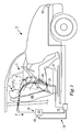
- FIG. 1 schematically illustrates a safety arrangement 1 of a vehicle 3.
- the vehicle 3 comprises a seat 5, in which a seat occupant 7 is seated and the safety arrangement 1.
- the seat occupant 7 has buckled up a seat belt 9, being a part of the safety arrangement 1.
- the safety arrangement 1 further comprises a first sensor 11, a collision detection system 13, a reversible restraint system 15, and a processor 17.
- the first sensor 11 is adapted for determining, directly or indirectly, a current length of pulled out seat belt 9.
- the collision detection system 13 is adapted for detecting an actual collision and/or an imminent collision.
- the reversible restraint system 15 comprises a retractor 16 for retracting the seat belt 9.
- the retractor 16 is adapted to retract the seat belt 9 by applying a retraction force F to the seat belt 9, in case of a collision or an imminent collision involving the vehicle 3 being detected by the collision detection system 13.
- a seat arrangement 19 comprises the seat 5, the seat belt 9 and the retractor 16.
- the safety arrangement 1 may also comprise a seat belt usage sensor 18, which is used to detect if the seat belt 9 is buckled up.
- the first sensor 11 is adapted to determine, directly or indirectly, a current length L of pulled out seat belt, e.g. by measuring the rotation of a retractor spool being used for storing the seat belt 9.
- An excessive length L ⁇ of pulled out seat belt is calculated as the difference between the current length L of pulled out seat belt and a minimum length L min of pulled out seat belt, when the seat belt 9 is in use by the current user, which is further described below in conjunction with Figure 3 .
- the calculations are made in the processor 17. Data about current length L are then sent from the first sensor 11 to the processor 17.
- the collision detection system 13 may comprise a remote sensor system, e.g. a camera system, an IR camera system, a radar, a lidar, an ultrasonic sensor system, an accelerometer and/or a vehicle dynamics sensor, such as a steering wheel angle sensor.
- the collision detection system 13 may comprise a contact sensor system, e.g. a piezoelectric sensor.
- the retraction of the seat belt 9 may be triggered directly by the remote sensor system detecting an imminent collision, and/or the triggering may be based on the actual contact between an object and the vehicle 3, i.e. an actual collision.
- the collision detection system 13 is connected to the processor 17.
- One or more sensors may be used by the collision detection system 13. They may be located at various positions in the vehicle 3 depending on type of sensor, both on the outside of the vehicle 3 and within the vehicle 3, e.g. at a front of the vehicle 3 as is illustrated or at a rear end of the vehicle 3.
- the seat belt 9 is intended to protect the seat belt user 7 in case of a collision involving the vehicle 3, but there is also provided at least one reversible restraint system 15 in the vehicle 3, which reversible restraint system 15 may cooperate with the seat belt 9 to protect the seat occupant 7 or which may function independently of the seat belt 9.
- the reversible restraint system 15 may comprise the seat belt retractor 16, as illustrated in Figure 1 , or a seat back inclination adjustment arrangement 27, as illustrated in Figure 4 . Both of these are associated to the seat 5, i.e. the reversible restraint system 15 is intended to be used by an occupant 7 of that seat 5.
- the reversible restraint system may function independently of the seat.
- a reversible restraint system may be used to adjust the position of the steering wheel, to adjust the position of a pedal and/or to adjust the position of the dashboard in relation to the seat occupant.
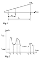
- the processor 17 is adapted for predicting a time T 0 , a point in time when the collision is predicted to affect a user 7 of the seat belt 9, for determining a selectable time period ⁇ 1 before the time T 0 , and for activating a reversible restraint system at the selectable time period before the time T 0 . See Figure 2 .
- the length of the selectable time period ⁇ 1 is a function of the determined current length of pulled out seat belt 9.
- the collision may affect a part of the vehicle 3, e.g. a bumper, before the time T 0 .
- the selectable time period ⁇ 1 starts at the time T 1 and lasts until the time T 0 .
- the reversible restraint system may be active during the whole selectable time period ⁇ 1 or during a selectable activation time period ⁇ 2 , lasting between the time and a time T 2 corresponding to a stop of activation of the reversible restraint system.
- the activation time period ⁇ 2 may also be a function of the determined current length of pulled out seat belt 9.
- FIG. 1 illustrates indicated by dashed lines a situation when the seat occupant 7 is leaning forwards. Therefore the current length of pulled out seat belt 9 is longer than if the seat occupant 7 would sit in a normal position, indicated by continuous lines.
- the seat belt 9 there is a first belt portion 21 running across the torso of the seat occupant 7 and a second belt portion 23 running over the hip of the seat occupant 7. If the seat occupant 7 leans forwards, it is primarily the length of the first belt portion 21, which is increased.
- the processor 17 sends a signal to the retractor 16 to retract the seat belt 9 by applying the retraction force F.
- the correctness of the prediction of a collision increases in general the closer to the time T 0 the prediction is made.
- the actual shape of the curve illustrating the correctness as a function of time may vary, e.g. dependent on sensor type and/or environmental conditions.
- Figure 2 illustrates a linearly increasing correctness. A late activation of the reversible restraint system reduces the risk of activating it incorrectly. If waiting until the time T 0 is reached, i.e. until the collision is actually affecting the user of the seat belt, the correctness would be close to 100% or substantially 100%.
- the time period utilized to pull in a seat belt may be between 0.1 s and 0.5 s or between 0.2 s and 0.4 s.
- the time period utilized to perform a pre-crash displacement of the seat or a portion thereof, e.g. to change the inclination of the seat back may be between 0.5 s and 3 s, or between 0.7 s and 1.5 s, or between 0.8 and 1.2 s, with s denoting seconds.
- the reversible restraint system 15 may be activated at a time, when the imminent collision is determined, or it may be activated at some point of time between when the imminent collision is determined and the time T 0 , when the collision is predicted to affect the user 7 of the seat belt 9. If activating the reversible restraint system 15 earlier than necessary, it will sometimes be activated although the collision is avoided. This may cause irritation and discomfort to the user 7.
- the appropriate time is found by means of the determined current length of pulled out seat belt 9.
- the seat belt 9 is not fully retracted, although it is desirable that it is fully retracted at the time T 0 , when the collision affects the user 7 of the seat belt 9, in order to give the best protection possible.
- a magnitude of the force used to operate the reversible restraint system may be selected, e.g. based on the determined current length of pulled out seat belt.
- the force may have a predefined level.
- Figure 3 illustrates an example of a series of measurements made of current length L of the seat belt 9 as a function of time.
- the current length L is repeatedly measured such that the series in practice can be plotted as a continuous curve.
- An excessive length L ⁇ of pulled out seat belt is calculated as the difference between the current length L of pulled out seat belt and a minimum length L min of pulled out seat belt, when the seat belt 9 is in use by the current user.
- the seat belt 9 When the seat belt 9 is not used, it hangs against the wall of the vehicle 3. It has then an unused length L unused . At the time t 0 the seat occupant 7 buckles up, a signal is sent from the seat belt usage sensor 18 to the processor 17. The seat occupant 7 is then seated in the seat 5 and has pulled out the seat belt 9.
- the minimum length L min is determined as the hitherto lowest value of the current length L, since the last time the seat belt 9 was buckled up.
- the value of the minimum length L min thus sinks gradually until the time t 1 , when the seat occupant 7 leans back against the seat back 25 of the seat 5. Thereafter, the seat occupant 7 leans forwards, interval t 1 to t 2 , and the values of the current length L increases.
- the minimum length L min remains unchanged.
- the excessive length L ⁇ of pulled out seat belt increases when the seat occupant 7 leans forwards.
- the current length L is continuously monitored as long as the seat belt 9 is buckled up. As soon as the current length L is less than the minimum length L min , a new value for the minimum length L min is provided, in Figure 3 after the time t 3 . Between time t 3 and t 4 the seat occupant 7 sits rather still leaning against the seat back 25. However, as the seat belt 9 moves a little over the body of the seat occupant 7, and as air is pressed out of the clothes, the current length L slowly decreases and new updated values of the minimum length L min are provided up until the time t 4 . Then the seat occupant 7 once against leans forwards and the current length L increases. The minimum length L min is thus maintained as it is. After a while, see time t 6 , the seat occupant 7 once again leans backwards against the seat back 25. However, the current length L is longer than the hitherto determined minimum length L min . The minimum length L min is thus not changed.
- the excessive length L ⁇ of pulled out seat belt 9 is utilized when determining the current length of pulled out seat belt in order to find an appropriate time of activation of the reversible restraint system, e.g. when activating the retractor 16 of Figure 1 .
- the current length of pulled out seat belt 9 may be determined by determining the shape of the seat occupant 7 and/or the position of the seat occupant 7 in relation to the seat 5, e.g. by means of a camera system or an IR camera system, and thereby indirectly determine the current length of pulled out seat belt 9. It is also possible to use a camera system to directly detect where the seat belt 9 is located and hence determine its pulled out length.
- FIG 4 illustrates another example of a safety arrangement 1' according to the invention, wherein the reversible restraint system 15' comprises a seat back inclination adjustment arrangement 27 and a second sensor 31 for determining a position of the seat back 25 relative to a squab 29 of the seat 5.
- the seat back inclination may be measured by means of a sensor in the seat back 25 or a sensor sensing its adjustment arrangement 27.
- the seat back 25 is inclined backwards, indicated by dashed lines. In case of collision, in particular a rear-end collision, it is more favourable that the seat back 25 assumes a more upright position, indicated by continuous lines.
- the seat back inclination adjustment arrangement 27 is arranged to displace the seat back 25 to the more upright position in case of a collision.
- the degree of inclination of the seat back 25 may be determined by determining the current length of pulled out seat belt 9, the second sensor 31 in that case coinciding with the first sensor 11.
- both these cases may be generalized as checking how much the current length of pulled out the seat belt 9 deviates from a goal value representing the seat occupant 7 sitting leaning against the seat back 25 with the seat back 25 in an upright position.
- the vehicle 3 may comprise both a retractor 16, being operated as described above in conjunction with Figure 1 , and a seat back inclination adjustment arrangement 27.
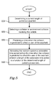
- Figure 5 is a flowchart of a method according to the invention. The method comprises:
Abstract
Description
- The present disclosure relates to a method for controlling a time of activation of a reversible restraint system in a vehicle, the vehicle comprising a seat belt associated to a seat and the restraint system. The disclosure further relates to a safety arrangement of a vehicle and to a vehicle.
- A modern vehicle, such as a car, is provided with safety arrangements in order to prevent or avoid injury to a seat occupant of the vehicle in case of an accident. It is well-known to use a safety arrangement comprising a seat belt for restraining the movement of the seat occupant in case of a sudden change of speed of the vehicle. Yet, a modern seat belt permits the seat occupant to move during normal driving conditions or when the vehicle stands still by adjusting the used length of the seat belt according to the movements of the seat occupant, e.g. when the seat occupant leans forwards.
- It is known to use a retractor to suddenly and forcefully retract the seat belt in case of a collision or imminent collision being detected, since it is beneficial for the seat occupant to be located close to a seat back and a headrest in such a situation. The sudden and forceful retraction of the seat belt may be uncomfortable for the seat occupant, and may even cause a minor injury to the seat occupant. However, the advantages of being seated close to the seat back and headrest in case of a collision outweigh any discomfort or minor injury.
- It is also known to reposition a seat or a portion of the seat, e.g. the seat back, in order to bring the seat occupant into a more favourable position. Purely as an example, if the seat back is inclined backwards, it may be beneficial to move it to a more upright position, e.g. in case of a rear-end collision.
- Document
EP 2 743 142 A1 discloses a method for retracting a seat belt of a vehicle, the method comprising the steps of determining an excessive length LΔ of pulled out seat belt, the excessive length LΔ of pulled out seat belt being the difference between the current length L and the minimum length Lmin of pulled out seat belt, when the seat belt is in use, and in case of detecting a collision or and/or a risk situation involving the vehicle, retracting the seat belt by applying a retraction force F, the retraction force F being a function of the excessive length LΔ of pulled out seat belt. - According to document
EP 2 743 142 A1 , the length of pulled out seat belt is utilized for determining a magnitude of the retraction force. In an embodiment, it is shown that the retraction force may, at least partly, be increasing as a function of the excessive length LΔ of pulled out seat belt. This means that a higher force will be used if the seat occupant is far from the seat back, as compared to if the seat occupant is close to the seat back. - The object of the present disclosure is to overcome or ameliorate at least one of the disadvantages of the prior art, or to provide a useful alternative.
- It is desirable to provide a method for controlling a time of activation of a reversible restraint system of a vehicle
- It is further desirable to provide a method being able to avoid unnecessary activations of the reversible restraint system.
- The object above may be achieved by the subject-matter of claim 1.
- Thus, in a first aspect of the present invention there is provided a method for controlling a time of activation of a restraint system in a vehicle, the vehicle comprising a seat belt associated to a seat and the restraint system, the restraint system being a reversible restraint system. The method comprises the steps of:
- a) determining a current length of pulled out seat belt,
- b) detecting a collision or an imminent collision involving the vehicle,
- c) predicting a time when the collision is predicted to affect a user of the seat belt,
- d) activating the reversible restraint system a selectable time period before the time when the collision is predicted to affect the user of the seat belt, wherein a length of the selectable time period is a function of the determined current length of pulled out seat belt.
- The vehicle comprises at least one seat having an associated seat belt, i.e. the seat belt is intended to be used by an occupant of that seat, i.e. a user of the seat belt. The seat belt may be attached to the seat and/or to a vehicle body adjacent to the seat.
- The seat belt is intended to protect the seat belt user in case of a collision involving the vehicle, but there is also provided at least one reversible restraint system in the vehicle, which reversible restraint system may cooperate with the seat belt to protect the seat occupant or which may function independently of the seat belt. The reversible restraint system may e.g. comprise a seat belt retractor or a seat back inclination adjustment arrangement. Both of these examples are associated to the seat, i.e. they are located in or at the seat and the restraint system is intended to be used by the occupant of that seat. Other reversible restraint systems do not form part of the seat arrangement but are anyway intended to protect the seat occupant. Purely as an example, a reversible restraint system may be used to adjust the position of the steering wheel, to adjust the position of a pedal and/or to adjust the position of the dashboard in relation to the seat occupant.
- The correctness of the prediction of a collision increases in general the closer to the time T0 the prediction is made, the time T0 being the time when the collision is predicted to affect the user of the seat belt. However, the actual shape of the curve showing the correctness as a function of time may vary, e.g. dependent on sensor type and/or environmental conditions. Hence, a late activation of a reversible restraint system reduces the risk of activating it incorrectly. Further, unnecessary activation may cause a nuisance to the seat occupant. If waiting until the time T0 is reached, i.e. until the collision is actually affecting the user of the seat belt, the correctness would be close to 100% or substantially 100%. The collision process may then have started already at another portion of the vehicle, e.g. affecting the bumper of the vehicle.
- It takes some time to operate the reversible restraint system. Purely as an example, the time period utilized to pull in a seat belt for seat belt retraction, may be between 0.1 s and 0.5 s or between 0.2 s and 0.4 s. Purely as another example, the time period utilized to perform a pre-crash displacement of the seat or a portion thereof, e.g. to change the inclination of the seat back, may be between 0.5 s and 3 s, or between 0.7 s and 1.5 s, or between 0.8 and 1.2 s, with s denoting seconds. Thus, if activating the reversible restraint system too late, it will not be fully functional, or at least sufficiently functional, at the time T0, when the collision is predicted to affect the user of the seat belt.
- The reversible restraint system may be activated at a time, when the imminent collision is determined, or it may be activated at some point of time between when the imminent collision is determined and the time T0, when the collision is predicted to affect the user of the seat belt. If activating the reversible restraint system earlier than necessary, it will sometimes be activated although the collision is avoided. This may cause irritation and discomfort to the user of the seat.
- It is consequently advantageous to find an appropriate time of activation of the reversible restraint system. According to the invention as described herein, the appropriate time is found by means of the determined current length of pulled out seat belt. It is in general desirable to activate the reversible restraint system as late as possible, but yet not so late that the reversible restraint system is not ready, or at least sufficiently operable, at the time, when the collision is predicted to affect the user of the seat belt. It may e.g. be acceptable that the seat belt is not fully retracted, although it is desirable that it is fully retracted when the collision affects the user of the seat belt in order to give the best protection possible.
- The current length of pulled out seat belt may be determined by measuring the rotation of a retractor spool being used for storing the seat belt. The current length of pulled out seat belt may be determined continuously or repeatedly. Thereby, there is always a representtative value available. The current length may for example be determined at least every second, preferably at least every 1/10 of a second and most preferably every 1/100 of a second.
- As an alternative or a complement, the current length of pulled out seat belt may be determined by determining the shape of the seat occupant and/or the position of the seat occupant in relation to the seat, e.g. by means of a camera system or an IR camera system, and thereby indirectly determine the current length of pulled out seat belt. It is also possible to use a camera system to directly detect where the seat belt is located and hence determine its pulled out length.
- The reversible restraint system may form part of a seat arrangement comprising the seat. The reversible restraint system may in that case comprise the retractor for the seat belt associated to the seat and/or the seat back inclination adjustment arrangement. The reversible restraint system is in that case associated to the seat.
- Other reversible restraint systems do not form part of the seat arrangement. Purely as an example, a reversible restraint system may be used to adjust the position of the steering wheel, to adjust the position of a pedal and/or to adjust the position of the dashboard in relation to the seat occupant.
- As mentioned above, the reversible restraint system may comprise a seat belt retractor. The retractor utilizes a retraction force to pull the seat belt back in case of a collision and/or a risk situation being detected, i.e. a situation of danger or potential danger. The risk situation may be that a collision is imminent or that a driver of the vehicle has lost control of the vehicle. It is then desirable to move the seat occupant back to a more favourable position against the seat back, e.g. in case the seat occupant is leaning forwards. The more the seat occupant leans forwards, the greater length of belt is pulled out.
- The retraction force should be differentiated from a pre-tension force used to keep the seat belt tensioned, when the seat occupant moves in the seat during normal driving conditions. The retraction force used is normally a number of times higher than the pre-tension force, e.g. at least twice, at least three times, at least five times, at least ten times or at least twenty times higher than the pre-tension force.
- As a complement, or an alternative, the reversible restraint system may comprise a seat back inclination adjustment arrangement. It may happen that the seat occupant puts the seat back in a backwards inclined position. In case of a collision, in particular a rear-end collision, it is more favourable that the seat back assumes a more upright position. Hence the seat back inclination adjustment arrangement is arranged to displace the seat back to the more upright position. The more the seat back is inclined backwards, the longer before the predicted collision it is desirable to start displacing the seat back. The degree of inclination of the seat back may be determined by determining the current length of pulled out seat belt or by using a separate sensor. The more the seat back is inclined backwards, the shorter length of seat belt is utilized. The seat back inclination may also be measured by means of a sensor in the seat back or a sensor checking its adjustment arrangement. This is opposite to the above-mentioned case, wherein the more the seat occupant leans forwards, the more the seat belt is pulled out. However, both these cases may be generalized as checking how much the current length of pulled out the seat belt deviates from a goal value representing the seat occupant sitting leaning against the seat back with the seat back in a correct position. The more the actual length of the seat belt deviates from this goal value, the earlier it is desirable to start activation of the reversible restraint system.
- Step a) of the method may further comprise determining an excessive length LΔ of pulled out seat belt, the excessive length LΔ of pulled out seat belt being the difference between the current length L and a minimum length Lmin of pulled out seat belt, when the seat belt is in use by a current user of the seat belt, and wherein in step d) the length of the selectable time period is a function of the determined excessive length LΔ of pulled out seat belt.
- The case with excessive length LΔ of pulled out seat belt may e.g. occur when the user of the seat belt leans forwards and/or wears fluffy clothes.
- The minimum length Lmin of pulled out seat belt relates to when the seat belt is in use by the current seat occupant and is the smallest determined length of pulled out seat belt for the current seat occupant, which generally corresponds to the seat occupant sitting upright in the seat.
- Since the excessive length LΔ of pulled out seat belt is determined as a difference, there is no need to measure the absolute length of the seat belt for the current length L and the minimum length Lmin, as long as the determined lengths relate to each other such that a difference may be calculated relating to the pulled out length.
- There are a couple of different lengths of the seat belt, which are used herein:
- Lunused
- length of unused seat belt, when hanging at the vehicle wall,
- Lempty
- length of seat belt when connected but seat empty,
- Lmin
- minimum length of seat belt when in use by the current user,
- L
- current length of seat belt when in use,
- LΔ
- excessive length of seat belt when in use,
- Lmax
- maximum value, physical length of seat belt.
- Further the following relationships are valid:


- When the seat belt is not used, it hangs against the wall of the vehicle. It has then an unused length, Lunused. The length of the seat belt when connected but the seat is empty, Lempty, represents a lower limit for the minimum value Lmin. The length of the seat belt when connected but the seat is empty, Lempty, will depend on the position of the seat in relation to the vehicle body. However the lowest value is obtained assuming that the seat is in a rearmost position. Even the thinnest person will add to the length, even when leaning fully back, such that the minimum length Lmin of pulled out seat belt is always larger than Lempty, as soon as the seat is used and the seat occupant utilizes the seat belt.
- The current length L for a particular seat occupant of the seat belt may vary between Lmin and Lmax. The lowest value, the minimum value Lmin, is obtained when the seat occupant leans against the seat back. The current length L increases, when the seat occupant leans forwards and decreases when the seat occupant leans backwards. A large and/or thick seat occupant will have longer lengths as regards minimum length Lmin and current length L than a small or thin seat occupant. The lengths are also influenced by the clothes worn by the seat occupant. Purely as an example a thick winter jacket will add more to the length than a T-shirt. The maximum length Lmax depends on the physical length of the seat belt and tells how far the seat belt can maximally be pulled out.
- The lengths relate to the amount of seat belt being pulled out from e.g. a storage magazine for the seat belt. The portion of the seat belt, which is currently not in use, may e.g. be stored as wound up on a spool in a retractor.
- The current length L of pulled out seat belt may be determined continuously or repeatedly. Thereby, there is always a representative value available. The current length L may for example be determined at least every second, preferably at least every 1/10 of a second and most preferably every 1/100 of a second.
- Also the minimum length Lmin may be determined continuously or repeatedly. This may be advantageous, since it may otherwise be difficult to determine for the individual seat occupant how long time it will take until the seat occupant leans backwards against the seat back. Further, also when the seat occupant leans against the seat back, the seat belt may move a little over the body of the seat occupant, and air may be pressed out of the clothes. The used length of the seat belt thereby slowly decreases and new values of the minimum length Lmin may successively be provided. A representative value of the minimum length Lmin, which approximates the true value, will in some cases not be determined until after the seat occupant has settled into the seat, the air has been pressed out of the clothes etc.
- The minimum length may be determined by determining the current length L a plurality of times, and determining the minimum length Lmin of pulled out seat belt as a minimum value of the determined plurality of current lengths L of pulled out seat belt. In that case, also the minimum length Lmin may have a varying value, e.g. being determined as the lowest value so far, e.g. since the particular seat occupant buckled up in the seat.
- In order to avoid false detections, it may be required that at least a number measured lengths, e.g. at least two, or at least two consecutive values, are below the currently determined minimum length Lmin, before the minimum length Lmin is set to a new value.
- As an alternative, or a complement, the minimum length Lmin may be determined by recalling it from a data storage memory, e.g. when recalling data about seat settings for a particular seat occupant. In that case, the recalled minimum length Lmin would not reflect the actual clothes being worn by the seat occupant, but would form a good approximation based on the stored data. Such a recalled value may also form a starting point for determining the minimum length Lmin from current length L values, since it is expected that the seat occupant, even if wearing thicker clothes will have an actual minimum length Lmin being within the stored minimum length Lmin plus compensation for the thicker clothes.
- In order to obtain a representative value of the minimum length Lmin it is assumed that the seat occupant, at least once, leans against the seat back. It is highly improbable that the seat occupant would not, at least once, lean against the seat back. However, if the seat occupant has not yet leaned against the seat back, the determined value of the minimum length Lmin will be the best approximation so far. The approximation will be more accurate, the closer the seat occupant has been leaning towards the seat back. In that case, the method will still be useful, even though it is preferred that the seat occupant, at least once, has leaned against the seat back.
- The method may comprise to retract at least the determined excessive length LΔ of pulled out seat belt. Since the retraction force is higher than the normal pre-tension force, a greater length of seat belt than the excessive length LΔ may be retracted, especially if the seat occupant wears fluffy clothes. In that case, the seat belt may be pulled back as far as the retraction force permits. The seat occupant may in such a case be pressed against the seat back by the seat belt.
- Further, even if there is too little time to retract the full excessive length LΔ, it is still useful to retract as much as possible of the excessive length LΔ in order to move the seat occupant as close as the available time will permit towards the seat back, before the seat belt user is affected by the collision.
- Step a) may comprise determining a position of the seat, to which the seat belt is associated in relation to the vehicle body, or determining a position of a portion of the seat e.g. a seat back, in relation to the vehicle body or to the rest of the seat, and wherein in step d) the length of the selectable time period is a function of the determined current length of pulled out seat belt and the determined position of the seat or seat portion.
- The reversible restraint system may be active during the whole selectable time period mentioned above or during a selectable activation time period, lasting during a portion of the selectable time period mentioned above. This corresponds to a stop of activation of the reversible restraint system. The activation time period may be a function of the determined current length of pulled out seat belt.
- The reversible restraint system may be operated with a force, wherein a magnitude of the force is a function of the determined current length of pulled out seat belt. The force may vary over the selectable time period. The magnitude of the force may influence the length of the selectable time period. As an alternative, the force may have a predefined level.
- In case the reversible restraint system comprises a retractor, the force may be used to retract the seat belt, i.e. being the retraction force mentioned above. The retraction force may, at least partly, increase as a function of the current length of pulled out seat belt. This means that a higher force will be used if the seat occupant is far from the seat back, as compared to if the seat occupant is close to the seat back. The function may be, at least partly, continuously increasing. Alternatively, the function may be stepwise increasing. The whole function may be increasing, or only part of it may be increasing while another part or other parts is/are constant.
- In case the reversible restraint system comprises an adjustment arrangement for the seat or a portion thereof, e.g. the seat back, the force may be used to reposition the seat or the portion thereof in order to obtain a more favourable position of the seat occupant. The force may then be higher the further away the seat or the portion thereof is from a favourable position.
- The method may optionally further comprise determining if a seat occupant is present in a seat, to which the seat belt is associated, the seat belt only being retracted, if it is determined that a seat occupant is present in the seat.
- If it is determined that there is no seat occupant present in the seat, there is no need to determine any lengths or to apply a retraction force. Sometimes, a bag or similar can be put in a seat and attached by applying the seat belt through e.g. a handle of the bag. Thereby, it can be avoided that the bag is thrown around in the vehicle in case of a sudden speed change of the vehicle. It may in such a case be favourable to anyway retract the seat belt, although the seat is occupied by an object, and not a person. The term seat occupant as used herein is thus not restricted to human beings, but may also include other objects or animals occupying the seat.
- The method may further optionally comprise determining if the seat belt is buckled up and the current length of pulled out seat belt, and optionally the excessive length of pulled out seat belt, may be determined since it was determined last time that the seat belt was buckled up.
- According to a standard configuration of the seat belt, there is a first belt portion running across the torso of the seat occupant and a second belt portion running over the hip of the seat occupant. If the seat occupant leans forwards or the seat back is inclined backwards, it is primarily the length of the first belt portion, which is influenced. The above-mentioned method may therefore be performed in relation to the length of first belt portion only, or in relation to the lengths of the first and second belt portions.
- In a second aspect of the present invention, there is provided a safety arrangement of a vehicle. The safety arrangement comprises
- a seat belt,
- a first sensor, for directly or indirectly determining a current length of pulled out seat belt,
- a system for detecting a collision or an imminent collision involving the vehicle,
- a reversible restraint system, and
- a processor.
- The processor is adapted to
- predict a time T0 when the collision is predicted to affect a user of the seat belt,
- determine a selectable time period before the time T0, and
- activate the reversible restraint system at the selectable time period before the time T0, wherein a length of the selectable time period is a function of the determined current length of pulled out seat belt.
- The first sensor may directly or indirectly measure a parameter corresponding to the current length of the seat belt being pulled out. The first sensor may e.g. directly measure the current length. Alternatively, it may measure the rotation of a retractor spool being used for storing the seat belt. It may e.g. measure the angular position of the retractor spool. Such sensors are known to the skilled person from e.g. the patent document
US 2007/0114768 A1 . As an alternative or a complement, the current length of pulled out seat belt may be determined by determining the shape of the seat occupant and/or the position of the seat occupant in relation to the seat, e.g. by means of a camera system or an IR camera system, and thereby indirectly determine the current length of pulled out seat belt. It is also possible to use a camera system to directly detect where the seat belt is located and hence determine its pulled out length. - The system for detecting a collision or an imminent collision involving the vehicle, i.e. the collision detection system, may comprise a remote sensor system, e.g. a camera system, an IR camera system, a radar, a lidar, an ultrasonic sensor system, an accelerometer and/or a vehicle dynamics sensor, such as a steering wheel angle sensor. As an alternative, or in addition, the system may comprise a contact sensor system, e.g. a piezoelectric sensor.
- The reversible restraint system may be triggered directly by the remote sensor system detecting an imminent collision or another risk situation, and/or the triggering may be based on the actual contact between an object and the vehicle, i.e. an actual collision. The collision detection system is connected to the processor. One or more sensors may be used by the collision detection system. The sensor may be located at various positions in the vehicle depending on type of sensor, both on the outside of the vehicle and within the vehicle. They may e.g. be located at a front of the vehicle intended to detect or predict a front-end collision, or at the rear-end intended to detect or predict a rear-end collision.
- The reversible restraint system may be adapted to be related to a seat, to which the seat belt is associated, or to a portion of the seat.
- The reversible restraint system may be related to the seat belt, e.g. the reversible restraint system comprising a retractor for the seat belt. The retractor may be electrical, e.g. utilizing an electrical motor, and be electronically controlled by the processor, e.g. by sending an electrical signal. Alternatively, the retractor may be mechanical. Such reversible retractors may be used more than once and do not have to be replaced after use as pyro-technically initiated retractors would have to be.
- The restraint system as used in the safety arrangement as described herein is reversible. This is in particular advantageous, if the restraint system would be activated in case of a risk situation, such as an imminent collision, since in that case the restraint system may be easily reset if it was activated unnecessarily, e.g. the collision was actually avoided or was less severe than anticipated. Thereby, a threshold for activating the restraint system may be set lower than for a non-reversible restraint system, since there is only a little effort, and/or cost, involved to reset it. The reversible restraint system may thus be activated already when a risk for a collision is detected. If instead using an irreversible restraint system, such as a one initiated by a pyrotechnical means, the vehicle would need to go to e.g. a garage or a workshop to replace the pyrotechnical means, thus resulting in cost and effort.
- The first sensor is adapted for determining a current length of pulled out seat belt. In that case, the processor may be adapted to determine an excessive length of pulled out seat belt as the difference between the current length of pulled out seat belt and a minimum length of pulled out seat belt, when the seat belt is in use by the current user, as is described above. The length of the selectable time period is then a function of the determined excessive length of pulled out seat belt, which in turn is a function of the determined current length. The excessive length may be caused by the seat occupant leaning forwards and/or wearing fluffy clothes.
- The safety arrangement may further comprise a second sensor for determining a position of a seat, to which the seat belt is associated, or for determining a position of a portion of the seat, e.g. an inclination of a seat back. The reversible restraint system may comprise a seat position adjustment arrangement and/or a seat back inclination adjustment arrangement. The seat back inclination may be measured by means of a sensor in the seat back or a sensor sensing the seat back inclination adjustment arrangement.
- There is no need to include a seat position detector in the safety arrangement according to the invention, since the current length of the pulled out seat belt may be determined without using the position of the seat, e.g. by utilizing the excessive length of pulled out seat belt, as is described above. However, it is an option to include a seat position detector as the second sensor, which second sensor may be used also for other tasks, such as determining the distance between the seat occupant and an airbag in the steering wheel or dashboard.
- A seat back inclination sensor may be used to determine the degree of inclination of the seat back in relation to a squab of the seat.
- The safety arrangement may further comprise a seat belt usage sensor. The seat belt sensor usage sensor is used to see if the seat belt is buckled up.
- The safety arrangement may form a part of a larger system of the vehicle, such as an anti-collision system. The safety arrangement may be associated with a driver-assist system, such that the reversible restraint system may be activated, if it is detected that the driver has lost control of the vehicle, which is an example of a risk situation, since losing control of the vehicle may lead to a collision.
- In a third aspect of the invention there is provided a vehicle comprising a safety arrangement as described herein.
- The present invention will hereinafter be further explained by means of non-limiting embodiments with reference to the appended drawings wherein:
- Fig. 1
- illustrates a vehicle with a safety arrangement according to a first embodiment of the invention,
- Fig. 2
- illustrates schematically correctness of the prediction of a collision as a function of time,
- Fig. 3
- illustrates current length L of pulled out seat belt as a function of time,
- Fig. 4
- illustrates a vehicle with a safety arrangement according to a second embodiment of the invention, and
- Fig. 5
- is a flowchart of a method according to the invention.
- It should be noted that the appended drawings are not necessarily drawn to scale and that the dimensions of some features of the present invention may have been exaggerated for the sake of clarity.
- The invention will, in the following, be exemplified by non-limiting embodiments. It should however be realized that the embodiments are included in order to explain principles of the invention and not to limit the scope of the invention, defined by the appended claims. Details from two or more of the embodiments may be combined with each other.
-
Figure 1 schematically illustrates a safety arrangement 1 of avehicle 3. Thevehicle 3 comprises aseat 5, in which a seat occupant 7 is seated and the safety arrangement 1. The seat occupant 7 has buckled up aseat belt 9, being a part of the safety arrangement 1. Hence the seat occupant 7 is a user of theseat belt 9. The safety arrangement 1 further comprises afirst sensor 11, acollision detection system 13, areversible restraint system 15, and aprocessor 17. Thefirst sensor 11 is adapted for determining, directly or indirectly, a current length of pulled outseat belt 9. Thecollision detection system 13 is adapted for detecting an actual collision and/or an imminent collision. Thereversible restraint system 15 comprises aretractor 16 for retracting theseat belt 9. Theretractor 16 is adapted to retract theseat belt 9 by applying a retraction force F to theseat belt 9, in case of a collision or an imminent collision involving thevehicle 3 being detected by thecollision detection system 13. Aseat arrangement 19 comprises theseat 5, theseat belt 9 and theretractor 16. As an option, the safety arrangement 1 may also comprise a seatbelt usage sensor 18, which is used to detect if theseat belt 9 is buckled up. - In the illustrated embodiment, the
first sensor 11 is adapted to determine, directly or indirectly, a current length L of pulled out seat belt, e.g. by measuring the rotation of a retractor spool being used for storing theseat belt 9. An excessive length LΔ of pulled out seat belt is calculated as the difference between the current length L of pulled out seat belt and a minimum length Lmin of pulled out seat belt, when theseat belt 9 is in use by the current user, which is further described below in conjunction withFigure 3 . The calculations are made in theprocessor 17. Data about current length L are then sent from thefirst sensor 11 to theprocessor 17. - The
collision detection system 13 may comprise a remote sensor system, e.g. a camera system, an IR camera system, a radar, a lidar, an ultrasonic sensor system, an accelerometer and/or a vehicle dynamics sensor, such as a steering wheel angle sensor. As an alternative, or in addition, thecollision detection system 13 may comprise a contact sensor system, e.g. a piezoelectric sensor. The retraction of theseat belt 9 may be triggered directly by the remote sensor system detecting an imminent collision, and/or the triggering may be based on the actual contact between an object and thevehicle 3, i.e. an actual collision. Thecollision detection system 13 is connected to theprocessor 17. One or more sensors may be used by thecollision detection system 13. They may be located at various positions in thevehicle 3 depending on type of sensor, both on the outside of thevehicle 3 and within thevehicle 3, e.g. at a front of thevehicle 3 as is illustrated or at a rear end of thevehicle 3. - The
seat belt 9 is intended to protect the seat belt user 7 in case of a collision involving thevehicle 3, but there is also provided at least onereversible restraint system 15 in thevehicle 3, whichreversible restraint system 15 may cooperate with theseat belt 9 to protect the seat occupant 7 or which may function independently of theseat belt 9. Thereversible restraint system 15 may comprise theseat belt retractor 16, as illustrated inFigure 1 , or a seat backinclination adjustment arrangement 27, as illustrated inFigure 4 . Both of these are associated to theseat 5, i.e. thereversible restraint system 15 is intended to be used by an occupant 7 of thatseat 5. As an alternative, or a complement, the reversible restraint system may function independently of the seat. Purely as an example, a reversible restraint system may be used to adjust the position of the steering wheel, to adjust the position of a pedal and/or to adjust the position of the dashboard in relation to the seat occupant. - The
processor 17 is adapted for predicting a time T0, a point in time when the collision is predicted to affect a user 7 of theseat belt 9, for determining a selectable time period Δ1 before the time T0, and for activating a reversible restraint system at the selectable time period before the time T0. SeeFigure 2 . The length of the selectable time period Δ1 is a function of the determined current length of pulled outseat belt 9. The collision may affect a part of thevehicle 3, e.g. a bumper, before the time T0. The selectable time period Δ1 starts at the time T1 and lasts until the time T0. The reversible restraint system may be active during the whole selectable time period Δ1 or during a selectable activation time period Δ2, lasting between the time and a time T2 corresponding to a stop of activation of the reversible restraint system. The activation time period Δ2 may also be a function of the determined current length of pulled outseat belt 9. - The embodiment illustrated in
Figure 1 illustrates indicated by dashed lines a situation when the seat occupant 7 is leaning forwards. Therefore the current length of pulled outseat belt 9 is longer than if the seat occupant 7 would sit in a normal position, indicated by continuous lines. According to a standard configuration of theseat belt 9, there is afirst belt portion 21 running across the torso of the seat occupant 7 and asecond belt portion 23 running over the hip of the seat occupant 7. If the seat occupant 7 leans forwards, it is primarily the length of thefirst belt portion 21, which is increased. In case of a collision, it is favourable that the seat occupant 7 is positioned with his/her back against a seat back 25. Therefore, in case of a collision and/or an imminent collision being detected by thecollision detection system 13, theprocessor 17 sends a signal to theretractor 16 to retract theseat belt 9 by applying the retraction force F. - The correctness of the prediction of a collision increases in general the closer to the time T0 the prediction is made. However, the actual shape of the curve illustrating the correctness as a function of time may vary, e.g. dependent on sensor type and/or environmental conditions.
Figure 2 , as an example illustrates a linearly increasing correctness. A late activation of the reversible restraint system reduces the risk of activating it incorrectly. If waiting until the time T0 is reached, i.e. until the collision is actually affecting the user of the seat belt, the correctness would be close to 100% or substantially 100%. - Normally it takes some time to operate a component of a reversible restraint system. Purely as an example, the time period utilized to pull in a seat belt, e.g. for seat belt retraction, may be between 0.1 s and 0.5 s or between 0.2 s and 0.4 s. Purely as another example, the time period utilized to perform a pre-crash displacement of the seat or a portion thereof, e.g. to change the inclination of the seat back, may be between 0.5 s and 3 s, or between 0.7 s and 1.5 s, or between 0.8 and 1.2 s, with s denoting seconds. Thus, if activating the reversible restraint system too late, it will not be fully or at least sufficiently functional at the time T0, when the collision is predicted to affect the user of the seat belt.
- The
reversible restraint system 15 may be activated at a time, when the imminent collision is determined, or it may be activated at some point of time between when the imminent collision is determined and the time T0, when the collision is predicted to affect the user 7 of theseat belt 9. If activating thereversible restraint system 15 earlier than necessary, it will sometimes be activated although the collision is avoided. This may cause irritation and discomfort to the user 7. - It is consequently advantageous to find an appropriate time of activation of the
reversible restraint system 15. According to the invention as described herein, the appropriate time is found by means of the determined current length of pulled outseat belt 9. As explained above, it is in general desirable to activate the reversible restraint system as late as possible, but yet not so late that the reversible restraint system is not ready or at least sufficiently operable at the time, when the collision is predicted to affect the user of the seat belt. It may e.g. be acceptable that theseat belt 9 is not fully retracted, although it is desirable that it is fully retracted at the time T0, when the collision affects the user 7 of theseat belt 9, in order to give the best protection possible. - In addition to finding an appropriate time of activation of the reversible restraint system, a magnitude of the force used to operate the reversible restraint system may be selected, e.g. based on the determined current length of pulled out seat belt. As an alternative, the force may have a predefined level.
-
Figure 3 illustrates an example of a series of measurements made of current length L of theseat belt 9 as a function of time. The current length L is repeatedly measured such that the series in practice can be plotted as a continuous curve. An excessive length LΔ of pulled out seat belt is calculated as the difference between the current length L of pulled out seat belt and a minimum length Lmin of pulled out seat belt, when theseat belt 9 is in use by the current user. - When the
seat belt 9 is not used, it hangs against the wall of thevehicle 3. It has then an unused length Lunused. At the time t0 the seat occupant 7 buckles up, a signal is sent from the seatbelt usage sensor 18 to theprocessor 17. The seat occupant 7 is then seated in theseat 5 and has pulled out theseat belt 9. - The minimum length Lmin is determined as the hitherto lowest value of the current length L, since the last time the
seat belt 9 was buckled up. The value of the minimum length Lmin thus sinks gradually until the time t1, when the seat occupant 7 leans back against the seat back 25 of theseat 5. Thereafter, the seat occupant 7 leans forwards, interval t1 to t2, and the values of the current length L increases. Hence the minimum length Lmin remains unchanged. However, the excessive length LΔ of pulled out seat belt increases when the seat occupant 7 leans forwards. - The current length L is continuously monitored as long as the
seat belt 9 is buckled up. As soon as the current length L is less than the minimum length Lmin, a new value for the minimum length Lmin is provided, inFigure 3 after the time t3. Between time t3 and t4 the seat occupant 7 sits rather still leaning against the seat back 25. However, as theseat belt 9 moves a little over the body of the seat occupant 7, and as air is pressed out of the clothes, the current length L slowly decreases and new updated values of the minimum length Lmin are provided up until the time t4. Then the seat occupant 7 once against leans forwards and the current length L increases. The minimum length Lmin is thus maintained as it is. After a while, see time t6, the seat occupant 7 once again leans backwards against the seat back 25. However, the current length L is longer than the hitherto determined minimum length Lmin. The minimum length Lmin is thus not changed. - In the illustrated embodiment of
Figure 1 , the excessive length LΔ of pulled outseat belt 9 is utilized when determining the current length of pulled out seat belt in order to find an appropriate time of activation of the reversible restraint system, e.g. when activating theretractor 16 ofFigure 1 . As an alternative or a complement, the current length of pulled outseat belt 9 may be determined by determining the shape of the seat occupant 7 and/or the position of the seat occupant 7 in relation to theseat 5, e.g. by means of a camera system or an IR camera system, and thereby indirectly determine the current length of pulled outseat belt 9. It is also possible to use a camera system to directly detect where theseat belt 9 is located and hence determine its pulled out length. -
Figure 4 illustrates another example of a safety arrangement 1' according to the invention, wherein the reversible restraint system 15' comprises a seat backinclination adjustment arrangement 27 and asecond sensor 31 for determining a position of the seat back 25 relative to a squab 29 of theseat 5. The seat back inclination may be measured by means of a sensor in the seat back 25 or a sensor sensing itsadjustment arrangement 27. The seat back 25 is inclined backwards, indicated by dashed lines. In case of collision, in particular a rear-end collision, it is more favourable that the seat back 25 assumes a more upright position, indicated by continuous lines. Hence the seat backinclination adjustment arrangement 27 is arranged to displace the seat back 25 to the more upright position in case of a collision. The more the seat back 25 is inclined backwards, the earlier it is desirable to start displacing the seat back 25. The degree of inclination of the seat back 25 may be determined by determining the current length of pulled outseat belt 9, thesecond sensor 31 in that case coinciding with thefirst sensor 11. The more the seat back 25 is inclined backwards, the shorter length ofseat belt 9 is utilized, hence opposite for the case ofFigure 1 , wherein the more the seat occupant 7 leans forwards, the more theseat belt 9 is pulled out. However, both these cases may be generalized as checking how much the current length of pulled out theseat belt 9 deviates from a goal value representing the seat occupant 7 sitting leaning against the seat back 25 with the seat back 25 in an upright position. The more the actual length of the seat belt deviates from this goal value, the earlier it is desirable to start activation of thereversible restraint system 15, 15'. - As for example illustrated in
Figure 4 , thevehicle 3 may comprise both aretractor 16, being operated as described above in conjunction withFigure 1 , and a seat backinclination adjustment arrangement 27. -
Figure 5 is a flowchart of a method according to the invention. The method comprises: - 110: Determining a current length of pulled out seat belt.
- 120: Detecting a collision or an imminent collision involving the vehicle.
- 130: Predicting a time when the collision is predicted to affect a user of the seat belt.
- 140: Activating the reversible restraint system a selectable time period before the time when the collision is predicted to affect the user of the seat belt, wherein a length of the selectable time period is a function of the determined current length of pulled out seat belt.
- The steps of the method are further described above.
- Further modifications of the invention within the scope of the appended claims are feasible. As such, the present invention should not be considered as limited by the embodiments and figures described herein. Rather, the full scope of the invention should be determined by the appended claims, with reference to the description and drawings.
Claims (13)
- A method for controlling a time of activation of a restraint system (15, 15') in a vehicle (3), said vehicle comprising a seat belt (9) associated to a seat (5) and said restraint system, said restraint system being a reversible restraint system, said method comprising the steps ofa) determining a current length (L) of pulled out seat belt (9),b) detecting a collision or an imminent collision involving said vehicle (3),c) predicting a time (T0) when said collision is predicted to affect a user (7) of said seat belt (9),d) activating said reversible restraint system (15, 15') a selectable time period (Δ1) before said time (T0) when said collision is predicted to affect said user (7) of said seat belt (9), wherein a length of said selectable time period (Δ1) is a function of said determined current length (L) of pulled out seat belt (9).
- The method according to claim 1, wherein said current length (L) of pulled out seat belt (9) is determined continuously or repeatedly.
- The method according to claim 1 or 2, wherein said reversible restraint system (15, 15') forms part of a seat arrangement (19) comprising said seat (5), said reversible restraint system (15, 15') optionally comprising a retractor (16) for said seat belt (9) associated to said seat (5) and/or a seat back inclination adjustment arrangement (27).
- The method according to any one of the preceding claims,
wherein step a) further comprises determining an excessive length (LΔ) of pulled out seat belt, said excessive length (LΔ) of pulled out seat belt being the difference between said current length (L) and a minimum length (Lmin) of pulled out seat belt, when said seat belt (9) is in use by a current user (7) of said seat belt (9),
and wherein in step d) said length of said selectable time period (Δ1) is a function of said determined excessive length (LΔ) of pulled out seat belt (9). - The method according to any one of claims 3-4,
wherein step a) further comprises determining a position of said seat (5), to which said seat belt (9) is associated, or determining a position of a portion of said seat e.g. a seat back (25),
and wherein in step d) said length of said selectable time period (Δ1) is a function of said determined current length (L) of pulled out seat belt (9) and said determined position of said seat (5) or seat portion (25). - The method according to any one of the preceding claims,
wherein said reversible restraint system (15, 15') is active during a selectable activation time period (Δ2), said activation time period (Δ2) being a function of said determined current length (L) of pulled out seat belt (9). - The method according to any one of the preceding claims,
wherein said reversible restraint system (15, 15') is operated with a force (F), wherein a magnitude of said force (F) is a function of said determined current length (L) of pulled out seat belt (9). - A safety arrangement (1, 1') of a vehicle (3) comprising- a seat belt (9),- a first sensor (11), for directly or indirectly determining a current length (L) of pulled out seat belt,- a system (13) for detecting a collision or an imminent collision involving said vehicle (3),- a reversible restraint system (15, 15'), and- a processor (17), which is adapted for predicting a time (T0) when said collision is predicted to affect a user (7) of said seat belt (9), for determining a selectable time period (Δ1) before said time (T0), and for activating said reversible restraint system (15, 15') at said selectable time period (Δ1) before said time (T0), wherein a length of said selectable time period (Δ1) is a function of said determined current length (L) of pulled out seat belt (9).
- The safety arrangement (1,1') according to claim 8, wherein said reversible restraint system (15, 15') is adapted to be related to a seat (5), to which said seat belt (9) is associated, or to a portion (25) of said seat.
- The safety arrangement (1,1') according to claim 8 or 9, wherein said reversible restraint system (15) is related to said seat belt (9), e.g. said reversible restraint system (15) comprising a retractor (16) for said seat belt (9).
- The safety arrangement (1,1') according to any one of claims 8-10, wherein said first sensor (11) is adapted for determining said current length (L) of pulled out seat belt, and said processor is adapted to determine an excessive length (LΔ) of pulled out seat belt as the difference between said current length (L) of pulled out seat belt and a minimum length (Lmin) of pulled out seat belt, when said seat belt (9) is in use by a current user (7), said length of said selectable time period (Δ1) being a function of said determined excessive length (LΔ) of pulled out seat belt (9).
- The safety arrangement (1,1') according to any one of claims 8-11 further comprising- a second sensor (31) for determining a position of a seat (5), to which said seat belt (9) is associated, or for determining a position of a portion (25) of said seat (5),said reversible restraint system (15, 15') comprising a seat position adjustment arrangement and/or a seat back inclination adjustment arrangement (27).
- A vehicle (3) comprising a safety arrangement (1,1') according to any one of claims 8-12.
Priority Applications (3)
| Application Number | Priority Date | Filing Date | Title |
|---|---|---|---|
| EP14192040.5A EP3018010B1 (en) | 2014-11-06 | 2014-11-06 | Method for controlling a time of activation of a reversible restraint system in a vehicle |
| CN201510706823.0A CN105584445B (en) | 2014-11-06 | 2015-10-27 | Method for controlling the triggered time of occupant restraint system reversible in vehicle |
| US14/925,107 US10035491B2 (en) | 2014-11-06 | 2015-10-28 | Method for controlling a time of activation of a reversible restraint system in a vehicle |
Applications Claiming Priority (1)
| Application Number | Priority Date | Filing Date | Title |
|---|---|---|---|
| EP14192040.5A EP3018010B1 (en) | 2014-11-06 | 2014-11-06 | Method for controlling a time of activation of a reversible restraint system in a vehicle |
Publications (2)
| Publication Number | Publication Date |
|---|---|
| EP3018010A1 true EP3018010A1 (en) | 2016-05-11 |
| EP3018010B1 EP3018010B1 (en) | 2018-01-10 |
Family
ID=51903808
Family Applications (1)
| Application Number | Title | Priority Date | Filing Date |
|---|---|---|---|
| EP14192040.5A Active EP3018010B1 (en) | 2014-11-06 | 2014-11-06 | Method for controlling a time of activation of a reversible restraint system in a vehicle |
Country Status (3)
| Country | Link |
|---|---|
| US (1) | US10035491B2 (en) |
| EP (1) | EP3018010B1 (en) |
| CN (1) | CN105584445B (en) |
Cited By (2)
| Publication number | Priority date | Publication date | Assignee | Title |
|---|---|---|---|---|
| WO2018129694A1 (en) * | 2017-01-12 | 2018-07-19 | 北京孙寅贵绿色科技研究院有限公司 | Intelligent safety belt, load limiter and retractor for vehicle |
| WO2019197120A1 (en) * | 2018-04-12 | 2019-10-17 | Daimler Ag | Method and device for activating a reversible seat belt tightener, and vehicle |
Families Citing this family (9)
| Publication number | Priority date | Publication date | Assignee | Title |
|---|---|---|---|---|
| EP2808206B1 (en) * | 2013-05-27 | 2017-07-12 | Volvo Car Corporation | Method and system of a vehicle for reversible seat belt retraction |
| EP3018010B1 (en) * | 2014-11-06 | 2018-01-10 | Volvo Car Corporation | Method for controlling a time of activation of a reversible restraint system in a vehicle |
| US9821761B2 (en) * | 2015-11-20 | 2017-11-21 | Ford Global Technologies, Llc | System and method for webbing payout |
| DE102017212527A1 (en) * | 2017-07-20 | 2019-01-24 | Robert Bosch Gmbh | A method and controller for providing a drive signal for driving at least one occupant protection device for a vehicle, belt sensor for a safety belt of a vehicle and safety system for a vehicle |
| DE102017009573B4 (en) * | 2017-10-14 | 2020-03-12 | Audi Ag | Method for operating a safety system for a motor vehicle, safety system and motor vehicle |
| EP3643567B1 (en) * | 2018-10-24 | 2021-05-05 | Volvo Car Corporation | Airbag arrangement |
| CN110843724B (en) * | 2019-11-27 | 2022-11-11 | 清华大学苏州汽车研究院(相城) | Control method of active pre-tightening system for shoulder belt of child safety seat |
| US11393225B2 (en) | 2019-12-06 | 2022-07-19 | Robert Bosch Gmbh | System and method for detecting abnormal settling of passengers in a vehicle |
| US11485383B2 (en) | 2019-12-06 | 2022-11-01 | Robert Bosch Gmbh | System and method for detecting and mitigating an unsafe condition in a vehicle |
Citations (3)
| Publication number | Priority date | Publication date | Assignee | Title |
|---|---|---|---|---|
| US20070114768A1 (en) | 2004-02-02 | 2007-05-24 | Anders Lennir | Safety arrangement |
| US20070257474A1 (en) * | 2006-05-08 | 2007-11-08 | Trw Automotive Gmbh | Vehicle occupant safety system and method for detecting the position of a vehicle occupant |
| EP2743142A1 (en) | 2012-12-12 | 2014-06-18 | Volvo Car Corporation | Method for retracting a seat belt |
Family Cites Families (29)
| Publication number | Priority date | Publication date | Assignee | Title |
|---|---|---|---|---|
| US7164117B2 (en) * | 1992-05-05 | 2007-01-16 | Automotive Technologies International, Inc. | Vehicular restraint system control system and method using multiple optical imagers |
| US4655312A (en) * | 1985-10-15 | 1987-04-07 | Allied Corporation | Electrically adjusted safety restraint system |
| US5184845A (en) * | 1988-05-20 | 1993-02-09 | Nissan Motor Co., Ltd. | Air-bag system |
| US5004178A (en) * | 1988-10-17 | 1991-04-02 | Jidosha Denki Kogyo K.K. | Seat belt apparatus |
| JPH03157243A (en) * | 1989-11-13 | 1991-07-05 | Takata Kk | Seat belt system |
| JP2605922B2 (en) * | 1990-04-18 | 1997-04-30 | 日産自動車株式会社 | Vehicle safety devices |
| JP2946995B2 (en) * | 1993-03-31 | 1999-09-13 | 日産自動車株式会社 | Vehicle seat belt device |
| KR100370808B1 (en) * | 1997-09-09 | 2003-02-05 | 지멘스 악티엔게젤샤프트 | Device for protecting occupants in an automobile and a method for controlling the inflation of a bag in an automobile |
| JP3296279B2 (en) * | 1997-12-10 | 2002-06-24 | 三菱自動車工業株式会社 | Vehicle airbag device |
| US6485057B1 (en) * | 1997-12-16 | 2002-11-26 | Nsk Autoliv Co., Ltd. | Automotive passenger restraint and protection apparatus and seatbelt protraction and retraction amount-detecting device |
| US6109697A (en) * | 1998-02-20 | 2000-08-29 | Breed Automotive Technology, Inc. | Compact belt tightener |
| JP3819613B2 (en) * | 1998-10-15 | 2006-09-13 | 本田技研工業株式会社 | Vehicle travel safety device |
| US6213512B1 (en) * | 1998-12-14 | 2001-04-10 | Trw Inc. | Seat belt tightening apparatus |
| DE19957814C2 (en) * | 1999-12-01 | 2003-07-31 | Trw Automotive Electron & Comp | Gurtaufrollersystem |
| EP1203700B1 (en) * | 2000-11-06 | 2006-07-05 | Honda Giken Kogyo Kabushiki Kaisha | Vehicle occupant protection system |
| WO2002062630A1 (en) * | 2001-02-06 | 2002-08-15 | Autoliv Development Ab | A safety-belt arrangement |
| US7128343B2 (en) * | 2001-02-06 | 2006-10-31 | Autoliv Asp,Inc. | Safety-belt arrangement |
| JP3772693B2 (en) * | 2001-05-28 | 2006-05-10 | 日産自動車株式会社 | Vehicle occupant restraint system |
| JP3912260B2 (en) * | 2002-10-31 | 2007-05-09 | 日産自動車株式会社 | Vehicle seat belt device |
| JP3949061B2 (en) * | 2003-01-21 | 2007-07-25 | トヨタ自動車株式会社 | Vehicle seat belt device |
| JP3926748B2 (en) * | 2003-01-24 | 2007-06-06 | 本田技研工業株式会社 | Seat belt device |
| JP3951937B2 (en) * | 2003-02-25 | 2007-08-01 | 日産自動車株式会社 | Crew restraint system |
| JP4570141B2 (en) * | 2004-10-05 | 2010-10-27 | タカタ株式会社 | Seat belt retractor and seat belt device |
| JP4644549B2 (en) * | 2005-07-19 | 2011-03-02 | タカタ株式会社 | Seat belt retractor, seat belt device, vehicle with seat belt device |
| JP4956371B2 (en) * | 2007-10-25 | 2012-06-20 | タカタ株式会社 | Seat belt retractor and seat belt device provided with the same |
| EP2682318B1 (en) * | 2012-07-03 | 2015-01-28 | Volvo Car Corporation | Motor vehicle collision warning system |
| US10246030B2 (en) * | 2012-08-09 | 2019-04-02 | Toyota Jidosha Kabushiki Kaisha | Object detection apparatus and driving assistance apparatus |
| DE112013007129B4 (en) * | 2013-05-31 | 2021-08-12 | Toyota Jidosha Kabushiki Kaisha | Movement trajectory prediction device and movement trajectory prediction method |
| EP3018010B1 (en) * | 2014-11-06 | 2018-01-10 | Volvo Car Corporation | Method for controlling a time of activation of a reversible restraint system in a vehicle |
-
2014
- 2014-11-06 EP EP14192040.5A patent/EP3018010B1/en active Active
-
2015
- 2015-10-27 CN CN201510706823.0A patent/CN105584445B/en active Active
- 2015-10-28 US US14/925,107 patent/US10035491B2/en active Active
Patent Citations (4)
| Publication number | Priority date | Publication date | Assignee | Title |
|---|---|---|---|---|
| US20070114768A1 (en) | 2004-02-02 | 2007-05-24 | Anders Lennir | Safety arrangement |
| EP2036781A1 (en) * | 2004-02-02 | 2009-03-18 | Autoliv Development AB | A safety arrangement |
| US20070257474A1 (en) * | 2006-05-08 | 2007-11-08 | Trw Automotive Gmbh | Vehicle occupant safety system and method for detecting the position of a vehicle occupant |
| EP2743142A1 (en) | 2012-12-12 | 2014-06-18 | Volvo Car Corporation | Method for retracting a seat belt |
Cited By (2)
| Publication number | Priority date | Publication date | Assignee | Title |
|---|---|---|---|---|
| WO2018129694A1 (en) * | 2017-01-12 | 2018-07-19 | 北京孙寅贵绿色科技研究院有限公司 | Intelligent safety belt, load limiter and retractor for vehicle |
| WO2019197120A1 (en) * | 2018-04-12 | 2019-10-17 | Daimler Ag | Method and device for activating a reversible seat belt tightener, and vehicle |
Also Published As
| Publication number | Publication date |
|---|---|
| CN105584445B (en) | 2019-06-21 |
| US20160129881A1 (en) | 2016-05-12 |
| US10035491B2 (en) | 2018-07-31 |
| EP3018010B1 (en) | 2018-01-10 |
| CN105584445A (en) | 2016-05-18 |
Similar Documents
| Publication | Publication Date | Title |
|---|---|---|
| EP3018010B1 (en) | Method for controlling a time of activation of a reversible restraint system in a vehicle | |
| EP2743142B1 (en) | Method for retracting a seat belt | |
| US9604594B2 (en) | Method for operation of a safety arrangement in a vehicle | |
| US6666292B2 (en) | Seat occupant restraint system for vehicle | |
| US7469924B2 (en) | Apparatus for protecting a vehicle occupant | |
| EP1711380B1 (en) | A safety arrangement | |
| US10647281B2 (en) | Occupant restraining device for vehicle | |
| JP6233363B2 (en) | 4-point seat belt device. | |
| US20060064220A1 (en) | Object struck discrimination system and protection system | |
| US7325641B2 (en) | Method for actuating a reversible belt pretensioner | |
| US20070273139A1 (en) | Device for Ascertaining an Occupant Position in a Vehicle | |
| JP2001191894A (en) | Occupant sensor using seat belt | |
| CN108454560A (en) | Type variable force-limiting device control system for vehicle | |
| US11491940B2 (en) | System and method for detecting improper posture of an occupant using a seatbelt restraint system | |
| US7607511B2 (en) | Vehicle passenger-restraining device and method | |
| US7140641B2 (en) | Safety-belt arrangement | |
| GB2371780A (en) | A safety-belt arrangement | |
| JP5086889B2 (en) | Seat belt retractor | |
| JP4062219B2 (en) | Crew protection device | |
| KR101211107B1 (en) | A seat belt for controlling a webbing winding motor by an occupant's volume | |
| JP6718266B2 (en) | Vehicle occupant protection device | |
| JP5531051B2 (en) | Seat belt retractor | |
| JP6718268B2 (en) | Vehicle occupant protection device |
Legal Events
| Date | Code | Title | Description |
|---|---|---|---|
| PUAI | Public reference made under article 153(3) epc to a published international application that has entered the european phase |
Free format text: ORIGINAL CODE: 0009012 |
|
| AK | Designated contracting states |
Kind code of ref document: A1 Designated state(s): AL AT BE BG CH CY CZ DE DK EE ES FI FR GB GR HR HU IE IS IT LI LT LU LV MC MK MT NL NO PL PT RO RS SE SI SK SM TR |
|
| AX | Request for extension of the european patent |
Extension state: BA ME |
|
| 17P | Request for examination filed |
Effective date: 20161111 |
|
| RBV | Designated contracting states (corrected) |
Designated state(s): AL AT BE BG CH CY CZ DE DK EE ES FI FR GB GR HR HU IE IS IT LI LT LU LV MC MK MT NL NO PL PT RO RS SE SI SK SM TR |
|
| GRAP | Despatch of communication of intention to grant a patent |
Free format text: ORIGINAL CODE: EPIDOSNIGR1 |
|
| INTG | Intention to grant announced |
Effective date: 20170823 |
|
| GRAS | Grant fee paid |
Free format text: ORIGINAL CODE: EPIDOSNIGR3 |
|
| GRAA | (expected) grant |
Free format text: ORIGINAL CODE: 0009210 |
|
| AK | Designated contracting states |
Kind code of ref document: B1 Designated state(s): AL AT BE BG CH CY CZ DE DK EE ES FI FR GB GR HR HU IE IS IT LI LT LU LV MC MK MT NL NO PL PT RO RS SE SI SK SM TR |
|
| REG | Reference to a national code |
Ref country code: CH Ref legal event code: EP Ref country code: AT Ref legal event code: REF Ref document number: 962024 Country of ref document: AT Kind code of ref document: T Effective date: 20180115 |
|
| REG | Reference to a national code |
Ref country code: IE Ref legal event code: FG4D |
|
| REG | Reference to a national code |
Ref country code: DE Ref legal event code: R096 Ref document number: 602014019626 Country of ref document: DE |
|
| REG | Reference to a national code |
Ref country code: SE Ref legal event code: TRGR |
|
| REG | Reference to a national code |
Ref country code: NL Ref legal event code: MP Effective date: 20180110 |
|
| REG | Reference to a national code |
Ref country code: AT Ref legal event code: MK05 Ref document number: 962024 Country of ref document: AT Kind code of ref document: T Effective date: 20180110 |
|
| PG25 | Lapsed in a contracting state [announced via postgrant information from national office to epo] |
Ref country code: NL Free format text: LAPSE BECAUSE OF FAILURE TO SUBMIT A TRANSLATION OF THE DESCRIPTION OR TO PAY THE FEE WITHIN THE PRESCRIBED TIME-LIMIT Effective date: 20180110 |
|
| PG25 | Lapsed in a contracting state [announced via postgrant information from national office to epo] |
Ref country code: HR Free format text: LAPSE BECAUSE OF FAILURE TO SUBMIT A TRANSLATION OF THE DESCRIPTION OR TO PAY THE FEE WITHIN THE PRESCRIBED TIME-LIMIT Effective date: 20180110 Ref country code: CY Free format text: LAPSE BECAUSE OF FAILURE TO SUBMIT A TRANSLATION OF THE DESCRIPTION OR TO PAY THE FEE WITHIN THE PRESCRIBED TIME-LIMIT Effective date: 20180110 Ref country code: ES Free format text: LAPSE BECAUSE OF FAILURE TO SUBMIT A TRANSLATION OF THE DESCRIPTION OR TO PAY THE FEE WITHIN THE PRESCRIBED TIME-LIMIT Effective date: 20180110 Ref country code: LT Free format text: LAPSE BECAUSE OF FAILURE TO SUBMIT A TRANSLATION OF THE DESCRIPTION OR TO PAY THE FEE WITHIN THE PRESCRIBED TIME-LIMIT Effective date: 20180110 Ref country code: FI Free format text: LAPSE BECAUSE OF FAILURE TO SUBMIT A TRANSLATION OF THE DESCRIPTION OR TO PAY THE FEE WITHIN THE PRESCRIBED TIME-LIMIT Effective date: 20180110 Ref country code: NO Free format text: LAPSE BECAUSE OF FAILURE TO SUBMIT A TRANSLATION OF THE DESCRIPTION OR TO PAY THE FEE WITHIN THE PRESCRIBED TIME-LIMIT Effective date: 20180410 |
|
| PG25 | Lapsed in a contracting state [announced via postgrant information from national office to epo] |
Ref country code: AT Free format text: LAPSE BECAUSE OF FAILURE TO SUBMIT A TRANSLATION OF THE DESCRIPTION OR TO PAY THE FEE WITHIN THE PRESCRIBED TIME-LIMIT Effective date: 20180110 Ref country code: BG Free format text: LAPSE BECAUSE OF FAILURE TO SUBMIT A TRANSLATION OF THE DESCRIPTION OR TO PAY THE FEE WITHIN THE PRESCRIBED TIME-LIMIT Effective date: 20180410 Ref country code: GR Free format text: LAPSE BECAUSE OF FAILURE TO SUBMIT A TRANSLATION OF THE DESCRIPTION OR TO PAY THE FEE WITHIN THE PRESCRIBED TIME-LIMIT Effective date: 20180411 Ref country code: PL Free format text: LAPSE BECAUSE OF FAILURE TO SUBMIT A TRANSLATION OF THE DESCRIPTION OR TO PAY THE FEE WITHIN THE PRESCRIBED TIME-LIMIT Effective date: 20180110 Ref country code: RS Free format text: LAPSE BECAUSE OF FAILURE TO SUBMIT A TRANSLATION OF THE DESCRIPTION OR TO PAY THE FEE WITHIN THE PRESCRIBED TIME-LIMIT Effective date: 20180110 Ref country code: IS Free format text: LAPSE BECAUSE OF FAILURE TO SUBMIT A TRANSLATION OF THE DESCRIPTION OR TO PAY THE FEE WITHIN THE PRESCRIBED TIME-LIMIT Effective date: 20180510 Ref country code: LV Free format text: LAPSE BECAUSE OF FAILURE TO SUBMIT A TRANSLATION OF THE DESCRIPTION OR TO PAY THE FEE WITHIN THE PRESCRIBED TIME-LIMIT Effective date: 20180110 |
|
| REG | Reference to a national code |
Ref country code: DE Ref legal event code: R097 Ref document number: 602014019626 Country of ref document: DE |
|
| PG25 | Lapsed in a contracting state [announced via postgrant information from national office to epo] |
Ref country code: RO Free format text: LAPSE BECAUSE OF FAILURE TO SUBMIT A TRANSLATION OF THE DESCRIPTION OR TO PAY THE FEE WITHIN THE PRESCRIBED TIME-LIMIT Effective date: 20180110 Ref country code: AL Free format text: LAPSE BECAUSE OF FAILURE TO SUBMIT A TRANSLATION OF THE DESCRIPTION OR TO PAY THE FEE WITHIN THE PRESCRIBED TIME-LIMIT Effective date: 20180110 Ref country code: EE Free format text: LAPSE BECAUSE OF FAILURE TO SUBMIT A TRANSLATION OF THE DESCRIPTION OR TO PAY THE FEE WITHIN THE PRESCRIBED TIME-LIMIT Effective date: 20180110 Ref country code: IT Free format text: LAPSE BECAUSE OF FAILURE TO SUBMIT A TRANSLATION OF THE DESCRIPTION OR TO PAY THE FEE WITHIN THE PRESCRIBED TIME-LIMIT Effective date: 20180110 |
|
| PLBE | No opposition filed within time limit |
Free format text: ORIGINAL CODE: 0009261 |
|
| STAA | Information on the status of an ep patent application or granted ep patent |
Free format text: STATUS: NO OPPOSITION FILED WITHIN TIME LIMIT |
|
| PG25 | Lapsed in a contracting state [announced via postgrant information from national office to epo] |
Ref country code: DK Free format text: LAPSE BECAUSE OF FAILURE TO SUBMIT A TRANSLATION OF THE DESCRIPTION OR TO PAY THE FEE WITHIN THE PRESCRIBED TIME-LIMIT Effective date: 20180110 Ref country code: SM Free format text: LAPSE BECAUSE OF FAILURE TO SUBMIT A TRANSLATION OF THE DESCRIPTION OR TO PAY THE FEE WITHIN THE PRESCRIBED TIME-LIMIT Effective date: 20180110 Ref country code: CZ Free format text: LAPSE BECAUSE OF FAILURE TO SUBMIT A TRANSLATION OF THE DESCRIPTION OR TO PAY THE FEE WITHIN THE PRESCRIBED TIME-LIMIT Effective date: 20180110 Ref country code: SK Free format text: LAPSE BECAUSE OF FAILURE TO SUBMIT A TRANSLATION OF THE DESCRIPTION OR TO PAY THE FEE WITHIN THE PRESCRIBED TIME-LIMIT Effective date: 20180110 |
|
| 26N | No opposition filed |
Effective date: 20181011 |
|
| PGFP | Annual fee paid to national office [announced via postgrant information from national office to epo] |
Ref country code: SE Payment date: 20181116 Year of fee payment: 5 |
|
| PG25 | Lapsed in a contracting state [announced via postgrant information from national office to epo] |
Ref country code: SI Free format text: LAPSE BECAUSE OF FAILURE TO SUBMIT A TRANSLATION OF THE DESCRIPTION OR TO PAY THE FEE WITHIN THE PRESCRIBED TIME-LIMIT Effective date: 20180110 |
|
| PGFP | Annual fee paid to national office [announced via postgrant information from national office to epo] |
Ref country code: GB Payment date: 20181114 Year of fee payment: 5 |
|
| REG | Reference to a national code |
Ref country code: CH Ref legal event code: PL |
|
| PG25 | Lapsed in a contracting state [announced via postgrant information from national office to epo] |
Ref country code: MC Free format text: LAPSE BECAUSE OF FAILURE TO SUBMIT A TRANSLATION OF THE DESCRIPTION OR TO PAY THE FEE WITHIN THE PRESCRIBED TIME-LIMIT Effective date: 20180110 Ref country code: LU Free format text: LAPSE BECAUSE OF NON-PAYMENT OF DUE FEES Effective date: 20181106 |
|
| REG | Reference to a national code |
Ref country code: BE Ref legal event code: MM Effective date: 20181130 |
|
| REG | Reference to a national code |
Ref country code: IE Ref legal event code: MM4A |
|
| PG25 | Lapsed in a contracting state [announced via postgrant information from national office to epo] |
Ref country code: LI Free format text: LAPSE BECAUSE OF NON-PAYMENT OF DUE FEES Effective date: 20181130 Ref country code: CH Free format text: LAPSE BECAUSE OF NON-PAYMENT OF DUE FEES Effective date: 20181130 |
|
| PG25 | Lapsed in a contracting state [announced via postgrant information from national office to epo] |
Ref country code: FR Free format text: LAPSE BECAUSE OF NON-PAYMENT OF DUE FEES Effective date: 20181130 Ref country code: IE Free format text: LAPSE BECAUSE OF NON-PAYMENT OF DUE FEES Effective date: 20181106 |
|
| PG25 | Lapsed in a contracting state [announced via postgrant information from national office to epo] |
Ref country code: BE Free format text: LAPSE BECAUSE OF NON-PAYMENT OF DUE FEES Effective date: 20181130 |
|
| PG25 | Lapsed in a contracting state [announced via postgrant information from national office to epo] |
Ref country code: MT Free format text: LAPSE BECAUSE OF NON-PAYMENT OF DUE FEES Effective date: 20181106 |
|
| PG25 | Lapsed in a contracting state [announced via postgrant information from national office to epo] |
Ref country code: TR Free format text: LAPSE BECAUSE OF FAILURE TO SUBMIT A TRANSLATION OF THE DESCRIPTION OR TO PAY THE FEE WITHIN THE PRESCRIBED TIME-LIMIT Effective date: 20180110 |
|
| PG25 | Lapsed in a contracting state [announced via postgrant information from national office to epo] |
Ref country code: PT Free format text: LAPSE BECAUSE OF FAILURE TO SUBMIT A TRANSLATION OF THE DESCRIPTION OR TO PAY THE FEE WITHIN THE PRESCRIBED TIME-LIMIT Effective date: 20180110 |
|
| PG25 | Lapsed in a contracting state [announced via postgrant information from national office to epo] |
Ref country code: HU Free format text: LAPSE BECAUSE OF FAILURE TO SUBMIT A TRANSLATION OF THE DESCRIPTION OR TO PAY THE FEE WITHIN THE PRESCRIBED TIME-LIMIT; INVALID AB INITIO Effective date: 20141106 Ref country code: MK Free format text: LAPSE BECAUSE OF NON-PAYMENT OF DUE FEES Effective date: 20180110 |
|
| REG | Reference to a national code |
Ref country code: SE Ref legal event code: EUG |
|
| PG25 | Lapsed in a contracting state [announced via postgrant information from national office to epo] |
Ref country code: SE Free format text: LAPSE BECAUSE OF NON-PAYMENT OF DUE FEES Effective date: 20191107 |
|
| GBPC | Gb: european patent ceased through non-payment of renewal fee |
Effective date: 20191106 |
|
| PG25 | Lapsed in a contracting state [announced via postgrant information from national office to epo] |
Ref country code: GB Free format text: LAPSE BECAUSE OF NON-PAYMENT OF DUE FEES Effective date: 20191106 |
|
| PGFP | Annual fee paid to national office [announced via postgrant information from national office to epo] |
Ref country code: DE Payment date: 20231019 Year of fee payment: 10 |