EP3017976A1 - Method of manufacturing rubber bushing-attached stabilizer bar, and rubber bushing-attached stabilizer bar - Google Patents
Method of manufacturing rubber bushing-attached stabilizer bar, and rubber bushing-attached stabilizer bar Download PDFInfo
- Publication number
- EP3017976A1 EP3017976A1 EP15825781.6A EP15825781A EP3017976A1 EP 3017976 A1 EP3017976 A1 EP 3017976A1 EP 15825781 A EP15825781 A EP 15825781A EP 3017976 A1 EP3017976 A1 EP 3017976A1
- Authority
- EP
- European Patent Office
- Prior art keywords
- stabilizer bar
- rubber bush
- adhered
- heating
- temperature
- Prior art date
- Legal status (The legal status is an assumption and is not a legal conclusion. Google has not performed a legal analysis and makes no representation as to the accuracy of the status listed.)
- Granted
Links
Images






Classifications
-
- B—PERFORMING OPERATIONS; TRANSPORTING
- B60—VEHICLES IN GENERAL
- B60G—VEHICLE SUSPENSION ARRANGEMENTS
- B60G21/00—Interconnection systems for two or more resiliently-suspended wheels, e.g. for stabilising a vehicle body with respect to acceleration, deceleration or centrifugal forces
- B60G21/02—Interconnection systems for two or more resiliently-suspended wheels, e.g. for stabilising a vehicle body with respect to acceleration, deceleration or centrifugal forces permanently interconnected
- B60G21/04—Interconnection systems for two or more resiliently-suspended wheels, e.g. for stabilising a vehicle body with respect to acceleration, deceleration or centrifugal forces permanently interconnected mechanically
- B60G21/05—Interconnection systems for two or more resiliently-suspended wheels, e.g. for stabilising a vehicle body with respect to acceleration, deceleration or centrifugal forces permanently interconnected mechanically between wheels on the same axle but on different sides of the vehicle, i.e. the left and right wheel suspensions being interconnected
- B60G21/055—Stabiliser bars
-
- B—PERFORMING OPERATIONS; TRANSPORTING
- B60—VEHICLES IN GENERAL
- B60G—VEHICLE SUSPENSION ARRANGEMENTS
- B60G21/00—Interconnection systems for two or more resiliently-suspended wheels, e.g. for stabilising a vehicle body with respect to acceleration, deceleration or centrifugal forces
- B60G21/02—Interconnection systems for two or more resiliently-suspended wheels, e.g. for stabilising a vehicle body with respect to acceleration, deceleration or centrifugal forces permanently interconnected
- B60G21/04—Interconnection systems for two or more resiliently-suspended wheels, e.g. for stabilising a vehicle body with respect to acceleration, deceleration or centrifugal forces permanently interconnected mechanically
- B60G21/05—Interconnection systems for two or more resiliently-suspended wheels, e.g. for stabilising a vehicle body with respect to acceleration, deceleration or centrifugal forces permanently interconnected mechanically between wheels on the same axle but on different sides of the vehicle, i.e. the left and right wheel suspensions being interconnected
- B60G21/055—Stabiliser bars
- B60G21/0551—Mounting means therefor
-
- B—PERFORMING OPERATIONS; TRANSPORTING
- B29—WORKING OF PLASTICS; WORKING OF SUBSTANCES IN A PLASTIC STATE IN GENERAL
- B29C—SHAPING OR JOINING OF PLASTICS; SHAPING OF MATERIAL IN A PLASTIC STATE, NOT OTHERWISE PROVIDED FOR; AFTER-TREATMENT OF THE SHAPED PRODUCTS, e.g. REPAIRING
- B29C65/00—Joining or sealing of preformed parts, e.g. welding of plastics materials; Apparatus therefor
- B29C65/02—Joining or sealing of preformed parts, e.g. welding of plastics materials; Apparatus therefor by heating, with or without pressure
-
- B—PERFORMING OPERATIONS; TRANSPORTING
- B29—WORKING OF PLASTICS; WORKING OF SUBSTANCES IN A PLASTIC STATE IN GENERAL
- B29C—SHAPING OR JOINING OF PLASTICS; SHAPING OF MATERIAL IN A PLASTIC STATE, NOT OTHERWISE PROVIDED FOR; AFTER-TREATMENT OF THE SHAPED PRODUCTS, e.g. REPAIRING
- B29C65/00—Joining or sealing of preformed parts, e.g. welding of plastics materials; Apparatus therefor
- B29C65/02—Joining or sealing of preformed parts, e.g. welding of plastics materials; Apparatus therefor by heating, with or without pressure
- B29C65/44—Joining a heated non plastics element to a plastics element
- B29C65/46—Joining a heated non plastics element to a plastics element heated by induction
-
- B—PERFORMING OPERATIONS; TRANSPORTING
- B29—WORKING OF PLASTICS; WORKING OF SUBSTANCES IN A PLASTIC STATE IN GENERAL
- B29C—SHAPING OR JOINING OF PLASTICS; SHAPING OF MATERIAL IN A PLASTIC STATE, NOT OTHERWISE PROVIDED FOR; AFTER-TREATMENT OF THE SHAPED PRODUCTS, e.g. REPAIRING
- B29C65/00—Joining or sealing of preformed parts, e.g. welding of plastics materials; Apparatus therefor
- B29C65/48—Joining or sealing of preformed parts, e.g. welding of plastics materials; Apparatus therefor using adhesives, i.e. using supplementary joining material; solvent bonding
-
- B—PERFORMING OPERATIONS; TRANSPORTING
- B29—WORKING OF PLASTICS; WORKING OF SUBSTANCES IN A PLASTIC STATE IN GENERAL
- B29C—SHAPING OR JOINING OF PLASTICS; SHAPING OF MATERIAL IN A PLASTIC STATE, NOT OTHERWISE PROVIDED FOR; AFTER-TREATMENT OF THE SHAPED PRODUCTS, e.g. REPAIRING
- B29C65/00—Joining or sealing of preformed parts, e.g. welding of plastics materials; Apparatus therefor
- B29C65/48—Joining or sealing of preformed parts, e.g. welding of plastics materials; Apparatus therefor using adhesives, i.e. using supplementary joining material; solvent bonding
- B29C65/4805—Joining or sealing of preformed parts, e.g. welding of plastics materials; Apparatus therefor using adhesives, i.e. using supplementary joining material; solvent bonding characterised by the type of adhesives
- B29C65/483—Reactive adhesives, e.g. chemically curing adhesives
- B29C65/4835—Heat curing adhesives
-
- B—PERFORMING OPERATIONS; TRANSPORTING
- B29—WORKING OF PLASTICS; WORKING OF SUBSTANCES IN A PLASTIC STATE IN GENERAL
- B29C—SHAPING OR JOINING OF PLASTICS; SHAPING OF MATERIAL IN A PLASTIC STATE, NOT OTHERWISE PROVIDED FOR; AFTER-TREATMENT OF THE SHAPED PRODUCTS, e.g. REPAIRING
- B29C65/00—Joining or sealing of preformed parts, e.g. welding of plastics materials; Apparatus therefor
- B29C65/56—Joining or sealing of preformed parts, e.g. welding of plastics materials; Apparatus therefor using mechanical means or mechanical connections, e.g. form-fits
- B29C65/562—Joining or sealing of preformed parts, e.g. welding of plastics materials; Apparatus therefor using mechanical means or mechanical connections, e.g. form-fits using extra joining elements, i.e. which are not integral with the parts to be joined
-
- B—PERFORMING OPERATIONS; TRANSPORTING
- B29—WORKING OF PLASTICS; WORKING OF SUBSTANCES IN A PLASTIC STATE IN GENERAL
- B29C—SHAPING OR JOINING OF PLASTICS; SHAPING OF MATERIAL IN A PLASTIC STATE, NOT OTHERWISE PROVIDED FOR; AFTER-TREATMENT OF THE SHAPED PRODUCTS, e.g. REPAIRING
- B29C65/00—Joining or sealing of preformed parts, e.g. welding of plastics materials; Apparatus therefor
- B29C65/72—Joining or sealing of preformed parts, e.g. welding of plastics materials; Apparatus therefor by combined operations or combined techniques, e.g. welding and stitching
-
- B—PERFORMING OPERATIONS; TRANSPORTING
- B29—WORKING OF PLASTICS; WORKING OF SUBSTANCES IN A PLASTIC STATE IN GENERAL
- B29C—SHAPING OR JOINING OF PLASTICS; SHAPING OF MATERIAL IN A PLASTIC STATE, NOT OTHERWISE PROVIDED FOR; AFTER-TREATMENT OF THE SHAPED PRODUCTS, e.g. REPAIRING
- B29C66/00—General aspects of processes or apparatus for joining preformed parts
- B29C66/50—General aspects of joining tubular articles; General aspects of joining long products, i.e. bars or profiled elements; General aspects of joining single elements to tubular articles, hollow articles or bars; General aspects of joining several hollow-preforms to form hollow or tubular articles
- B29C66/51—Joining tubular articles, profiled elements or bars; Joining single elements to tubular articles, hollow articles or bars; Joining several hollow-preforms to form hollow or tubular articles
- B29C66/53—Joining single elements to tubular articles, hollow articles or bars
- B29C66/532—Joining single elements to the wall of tubular articles, hollow articles or bars
-
- B—PERFORMING OPERATIONS; TRANSPORTING
- B29—WORKING OF PLASTICS; WORKING OF SUBSTANCES IN A PLASTIC STATE IN GENERAL
- B29C—SHAPING OR JOINING OF PLASTICS; SHAPING OF MATERIAL IN A PLASTIC STATE, NOT OTHERWISE PROVIDED FOR; AFTER-TREATMENT OF THE SHAPED PRODUCTS, e.g. REPAIRING
- B29C66/00—General aspects of processes or apparatus for joining preformed parts
- B29C66/50—General aspects of joining tubular articles; General aspects of joining long products, i.e. bars or profiled elements; General aspects of joining single elements to tubular articles, hollow articles or bars; General aspects of joining several hollow-preforms to form hollow or tubular articles
- B29C66/51—Joining tubular articles, profiled elements or bars; Joining single elements to tubular articles, hollow articles or bars; Joining several hollow-preforms to form hollow or tubular articles
- B29C66/53—Joining single elements to tubular articles, hollow articles or bars
- B29C66/532—Joining single elements to the wall of tubular articles, hollow articles or bars
- B29C66/5324—Joining single elements to the wall of tubular articles, hollow articles or bars said single elements being substantially annular, i.e. of finite length
- B29C66/53241—Joining single elements to the wall of tubular articles, hollow articles or bars said single elements being substantially annular, i.e. of finite length said articles being tubular and said substantially annular single elements being of finite length relative to the infinite length of said tubular articles
-
- B—PERFORMING OPERATIONS; TRANSPORTING
- B29—WORKING OF PLASTICS; WORKING OF SUBSTANCES IN A PLASTIC STATE IN GENERAL
- B29C—SHAPING OR JOINING OF PLASTICS; SHAPING OF MATERIAL IN A PLASTIC STATE, NOT OTHERWISE PROVIDED FOR; AFTER-TREATMENT OF THE SHAPED PRODUCTS, e.g. REPAIRING
- B29C66/00—General aspects of processes or apparatus for joining preformed parts
- B29C66/70—General aspects of processes or apparatus for joining preformed parts characterised by the composition, physical properties or the structure of the material of the parts to be joined; Joining with non-plastics material
- B29C66/71—General aspects of processes or apparatus for joining preformed parts characterised by the composition, physical properties or the structure of the material of the parts to be joined; Joining with non-plastics material characterised by the composition of the plastics material of the parts to be joined
-
- B—PERFORMING OPERATIONS; TRANSPORTING
- B29—WORKING OF PLASTICS; WORKING OF SUBSTANCES IN A PLASTIC STATE IN GENERAL
- B29C—SHAPING OR JOINING OF PLASTICS; SHAPING OF MATERIAL IN A PLASTIC STATE, NOT OTHERWISE PROVIDED FOR; AFTER-TREATMENT OF THE SHAPED PRODUCTS, e.g. REPAIRING
- B29C66/00—General aspects of processes or apparatus for joining preformed parts
- B29C66/70—General aspects of processes or apparatus for joining preformed parts characterised by the composition, physical properties or the structure of the material of the parts to be joined; Joining with non-plastics material
- B29C66/74—Joining plastics material to non-plastics material
- B29C66/742—Joining plastics material to non-plastics material to metals or their alloys
-
- B—PERFORMING OPERATIONS; TRANSPORTING
- B29—WORKING OF PLASTICS; WORKING OF SUBSTANCES IN A PLASTIC STATE IN GENERAL
- B29C—SHAPING OR JOINING OF PLASTICS; SHAPING OF MATERIAL IN A PLASTIC STATE, NOT OTHERWISE PROVIDED FOR; AFTER-TREATMENT OF THE SHAPED PRODUCTS, e.g. REPAIRING
- B29C66/00—General aspects of processes or apparatus for joining preformed parts
- B29C66/90—Measuring or controlling the joining process
- B29C66/91—Measuring or controlling the joining process by measuring or controlling the temperature, the heat or the thermal flux
- B29C66/914—Measuring or controlling the joining process by measuring or controlling the temperature, the heat or the thermal flux by controlling or regulating the temperature, the heat or the thermal flux
- B29C66/9141—Measuring or controlling the joining process by measuring or controlling the temperature, the heat or the thermal flux by controlling or regulating the temperature, the heat or the thermal flux by controlling or regulating the temperature
- B29C66/91411—Measuring or controlling the joining process by measuring or controlling the temperature, the heat or the thermal flux by controlling or regulating the temperature, the heat or the thermal flux by controlling or regulating the temperature of the parts to be joined, e.g. the joining process taking the temperature of the parts to be joined into account
-
- B—PERFORMING OPERATIONS; TRANSPORTING
- B29—WORKING OF PLASTICS; WORKING OF SUBSTANCES IN A PLASTIC STATE IN GENERAL
- B29C—SHAPING OR JOINING OF PLASTICS; SHAPING OF MATERIAL IN A PLASTIC STATE, NOT OTHERWISE PROVIDED FOR; AFTER-TREATMENT OF THE SHAPED PRODUCTS, e.g. REPAIRING
- B29C66/00—General aspects of processes or apparatus for joining preformed parts
- B29C66/90—Measuring or controlling the joining process
- B29C66/91—Measuring or controlling the joining process by measuring or controlling the temperature, the heat or the thermal flux
- B29C66/914—Measuring or controlling the joining process by measuring or controlling the temperature, the heat or the thermal flux by controlling or regulating the temperature, the heat or the thermal flux
- B29C66/9141—Measuring or controlling the joining process by measuring or controlling the temperature, the heat or the thermal flux by controlling or regulating the temperature, the heat or the thermal flux by controlling or regulating the temperature
- B29C66/91441—Measuring or controlling the joining process by measuring or controlling the temperature, the heat or the thermal flux by controlling or regulating the temperature, the heat or the thermal flux by controlling or regulating the temperature the temperature being non-constant over time
- B29C66/91443—Measuring or controlling the joining process by measuring or controlling the temperature, the heat or the thermal flux by controlling or regulating the temperature, the heat or the thermal flux by controlling or regulating the temperature the temperature being non-constant over time following a temperature-time profile
-
- B—PERFORMING OPERATIONS; TRANSPORTING
- B29—WORKING OF PLASTICS; WORKING OF SUBSTANCES IN A PLASTIC STATE IN GENERAL
- B29C—SHAPING OR JOINING OF PLASTICS; SHAPING OF MATERIAL IN A PLASTIC STATE, NOT OTHERWISE PROVIDED FOR; AFTER-TREATMENT OF THE SHAPED PRODUCTS, e.g. REPAIRING
- B29C66/00—General aspects of processes or apparatus for joining preformed parts
- B29C66/90—Measuring or controlling the joining process
- B29C66/91—Measuring or controlling the joining process by measuring or controlling the temperature, the heat or the thermal flux
- B29C66/919—Measuring or controlling the joining process by measuring or controlling the temperature, the heat or the thermal flux characterised by specific temperature, heat or thermal flux values or ranges
- B29C66/9192—Measuring or controlling the joining process by measuring or controlling the temperature, the heat or the thermal flux characterised by specific temperature, heat or thermal flux values or ranges in explicit relation to another variable, e.g. temperature diagrams
- B29C66/91951—Measuring or controlling the joining process by measuring or controlling the temperature, the heat or the thermal flux characterised by specific temperature, heat or thermal flux values or ranges in explicit relation to another variable, e.g. temperature diagrams in explicit relation to time, e.g. temperature-time diagrams
-
- F—MECHANICAL ENGINEERING; LIGHTING; HEATING; WEAPONS; BLASTING
- F16—ENGINEERING ELEMENTS AND UNITS; GENERAL MEASURES FOR PRODUCING AND MAINTAINING EFFECTIVE FUNCTIONING OF MACHINES OR INSTALLATIONS; THERMAL INSULATION IN GENERAL
- F16F—SPRINGS; SHOCK-ABSORBERS; MEANS FOR DAMPING VIBRATION
- F16F15/00—Suppression of vibrations in systems; Means or arrangements for avoiding or reducing out-of-balance forces, e.g. due to motion
- F16F15/02—Suppression of vibrations of non-rotating, e.g. reciprocating systems; Suppression of vibrations of rotating systems by use of members not moving with the rotating systems
- F16F15/04—Suppression of vibrations of non-rotating, e.g. reciprocating systems; Suppression of vibrations of rotating systems by use of members not moving with the rotating systems using elastic means
- F16F15/08—Suppression of vibrations of non-rotating, e.g. reciprocating systems; Suppression of vibrations of rotating systems by use of members not moving with the rotating systems using elastic means with rubber springs ; with springs made of rubber and metal
-
- B—PERFORMING OPERATIONS; TRANSPORTING
- B29—WORKING OF PLASTICS; WORKING OF SUBSTANCES IN A PLASTIC STATE IN GENERAL
- B29L—INDEXING SCHEME ASSOCIATED WITH SUBCLASS B29C, RELATING TO PARTICULAR ARTICLES
- B29L2031/00—Other particular articles
- B29L2031/04—Bearings
- B29L2031/045—Bushes therefor
-
- B—PERFORMING OPERATIONS; TRANSPORTING
- B29—WORKING OF PLASTICS; WORKING OF SUBSTANCES IN A PLASTIC STATE IN GENERAL
- B29L—INDEXING SCHEME ASSOCIATED WITH SUBCLASS B29C, RELATING TO PARTICULAR ARTICLES
- B29L2031/00—Other particular articles
- B29L2031/30—Vehicles, e.g. ships or aircraft, or body parts thereof
-
- B—PERFORMING OPERATIONS; TRANSPORTING
- B29—WORKING OF PLASTICS; WORKING OF SUBSTANCES IN A PLASTIC STATE IN GENERAL
- B29L—INDEXING SCHEME ASSOCIATED WITH SUBCLASS B29C, RELATING TO PARTICULAR ARTICLES
- B29L2031/00—Other particular articles
- B29L2031/721—Vibration dampening equipment, e.g. shock absorbers
-
- B—PERFORMING OPERATIONS; TRANSPORTING
- B60—VEHICLES IN GENERAL
- B60G—VEHICLE SUSPENSION ARRANGEMENTS
- B60G2202/00—Indexing codes relating to the type of spring, damper or actuator
- B60G2202/10—Type of spring
- B60G2202/13—Torsion spring
- B60G2202/135—Stabiliser bar and/or tube
-
- B—PERFORMING OPERATIONS; TRANSPORTING
- B60—VEHICLES IN GENERAL
- B60G—VEHICLE SUSPENSION ARRANGEMENTS
- B60G2204/00—Indexing codes related to suspensions per se or to auxiliary parts
- B60G2204/10—Mounting of suspension elements
- B60G2204/12—Mounting of springs or dampers
- B60G2204/122—Mounting of torsion springs
- B60G2204/1222—Middle mounts of stabiliser on vehicle body or chassis
-
- B—PERFORMING OPERATIONS; TRANSPORTING
- B60—VEHICLES IN GENERAL
- B60G—VEHICLE SUSPENSION ARRANGEMENTS
- B60G2204/00—Indexing codes related to suspensions per se or to auxiliary parts
- B60G2204/40—Auxiliary suspension parts; Adjustment of suspensions
- B60G2204/41—Elastic mounts, e.g. bushings
-
- B—PERFORMING OPERATIONS; TRANSPORTING
- B60—VEHICLES IN GENERAL
- B60G—VEHICLE SUSPENSION ARRANGEMENTS
- B60G2206/00—Indexing codes related to the manufacturing of suspensions: constructional features, the materials used, procedures or tools
- B60G2206/01—Constructional features of suspension elements, e.g. arms, dampers, springs
- B60G2206/40—Constructional features of dampers and/or springs
- B60G2206/42—Springs
- B60G2206/427—Stabiliser bars or tubes
-
- B—PERFORMING OPERATIONS; TRANSPORTING
- B60—VEHICLES IN GENERAL
- B60G—VEHICLE SUSPENSION ARRANGEMENTS
- B60G2206/00—Indexing codes related to the manufacturing of suspensions: constructional features, the materials used, procedures or tools
- B60G2206/01—Constructional features of suspension elements, e.g. arms, dampers, springs
- B60G2206/70—Materials used in suspensions
- B60G2206/73—Rubber; Elastomers
-
- B—PERFORMING OPERATIONS; TRANSPORTING
- B60—VEHICLES IN GENERAL
- B60G—VEHICLE SUSPENSION ARRANGEMENTS
- B60G2206/00—Indexing codes related to the manufacturing of suspensions: constructional features, the materials used, procedures or tools
- B60G2206/01—Constructional features of suspension elements, e.g. arms, dampers, springs
- B60G2206/80—Manufacturing procedures
-
- B—PERFORMING OPERATIONS; TRANSPORTING
- B60—VEHICLES IN GENERAL
- B60G—VEHICLE SUSPENSION ARRANGEMENTS
- B60G2206/00—Indexing codes related to the manufacturing of suspensions: constructional features, the materials used, procedures or tools
- B60G2206/01—Constructional features of suspension elements, e.g. arms, dampers, springs
- B60G2206/80—Manufacturing procedures
- B60G2206/82—Joining
-
- B—PERFORMING OPERATIONS; TRANSPORTING
- B60—VEHICLES IN GENERAL
- B60G—VEHICLE SUSPENSION ARRANGEMENTS
- B60G2206/00—Indexing codes related to the manufacturing of suspensions: constructional features, the materials used, procedures or tools
- B60G2206/01—Constructional features of suspension elements, e.g. arms, dampers, springs
- B60G2206/80—Manufacturing procedures
- B60G2206/82—Joining
- B60G2206/821—Joining by gluing
Definitions
- the present invention relates to a method of manufacturing a rubber bush provided stabilizer bar and a rubber bush provided stabilizer bar.
- a rubber bush provided stabilizer bar is connected to stabilize the position of the vehicle.
- the stabilizer bar is a member that mainly suppresses the body roll of the vehicle (rotational motion around a back and front direction of the vehicle body as an axis) using torsion toque.
- the rubber bush is attached between the stabilizer bar and the vehicle body and has a function to support the vehicle body by dampening transferring of the oscillation that is input to the stabilizer bar due to a condition of a road surface to the vehicle body, and flexibly following the movement of the stabilizer bar.
- the rubber bush provided stabilizer bar is mainly an unbonded type in which the stabilizer bar is only inserted in the rubber bush.
- the unbonded type has a problem in that strange noises are generated or positional shift between the stabilizer bar and the rubber bush occurs.
- a technique in which a rubber bush is adhered to a stabilizer bar by vulcanizing adhesion.
- a rubber bush provided with a centrum at which a vulcanizing adhesive (cure adhesive) is coated, is fitted on a portion to be adhered of the stabilizer bar. Then, portions of the stabilizer bar that are positioned outer side of the fitted position are heated by high-frequency induction heating to heat the portion to be adhered by heat conduction and cause a vulcanizing reaction so that the rubber bush and the stabilizer bar are adhered (see Patent Document 1, for example).
- Patent Document 1 Japanese Laid-open Patent Publication No. 2006-290313
- the portion to be adhered of the stabilizer bar is heated from the both outer side portions of the fitted rubber bush by heat conduction.
- the portion to be adhered at greater than or equal to 180 °C it is necessary to heat the both outer side portions of the rubber bush to be higher than the portion to be adhered such as 360 °C or the like, for example, or it is necessary to heat it at greater than or equal to 180 °C for a long period.
- the stabilizer bar is heated by high heat, poor appearance may occur such as clouding may occur at a coated surface of the heated position, or the coated film is damaged as being melted. Further, if it is heated for a long period, working efficiency is lowered and is not economic.
- Adhesion accuracy between the rubber bush and the stabilizer bar depends on an appropriate temperature management of the portion to be adhered.
- the temperature management is difficult because it is necessary to consider influences of efficiency of heat transfer, heat dissipation or the like.
- the adhesion accuracy may vary.
- the present invention is made in light of the above problems, and provides a method of manufacturing a rubber bush provided stabilizer bar capable of preventing poor appearance of the stabilizer bar and lowering of working efficiency, and stably obtaining high adhesion accuracy by appropriately performing a temperature management of a portion to be adhered.
- a method of manufacturing a rubber bush provided stabilizer bar by adhering a tubular shape rubber bush provided with a vulcanized centrum on a portion to be adhered of a stabilizer bar including: a coating step of coating a vulcanizing adhesive at a surface of a centrum of the rubber bush; a heating step of heating the portion to be adhered of the stabilizer bar; a fitting step of fitting the centrum of the rubber bush at which the vulcanizing adhesive is coated on the heated portion to be adhered of the stabilizer bar; and an adhering step of clamping the rubber bush in a radial direction by a clamping device to adhere the rubber bush on the portion to be adhered of the stabilizer bar.
- a method of manufacturing a rubber bush provided stabilizer bar can be provided capable of preventing poor appearance of the stabilizer bar and lowering of working efficiency, and stably obtaining high adhesion accuracy by appropriately performing a temperature management of a portion to be adhered.
- Fig. 1 is a perspective view illustrating the rubber bush provided stabilizer bar 1 of the first embodiment and suspensions k of front wheels of a vehicle.
- Fig. 2 is an exploded perspective view illustrating the structure of the rubber bush provided stabilizer bar 1.
- Fig. 3 is a perspective view illustrating the entirety of the rubber bush provided stabilizer bar 1.
- Fig. 4 is a cross-sectional view of Fig. 3 taken along line I-I.
- the rubber bush provided stabilizer bar 1 includes a stabilizer bar 2 composed of a metal solid member, and rubber bushes 3 that fix the stabilizer bar 2 to a frame portion FR of a vehicle body.
- the stabilizer bar 2 includes a torsion portion 21 that is bridged in a width direction X of the vehicle body, shoulder portions 22 that are positioned at both ends of the torsion portion 21, respectively, and arm portions 23 that extend from the shoulder portions 22, respectively, in a back and front direction Z of the vehicle body.
- the stabilizer bar 2 is formed such that its entirety has a substantially U shape.
- link members R are provided at front end portions of the arm portions 23 to be connected with acting portions of the suspensions k, respectively. It is assumed that inner side positions of the left and right shoulder portions 22 of the stabilizer bar 2 are portions to be adhered 20 (see Fig. 2 ) on which the rubber bushes 3 are adhered, respectively.
- the surface of the above described stabilizer bar 2 is coated by an epoxy or epoxypolyester coating by cationic electrodeposition coating or powder coating.
- a heating step of the stabilizer bar is separately performed as a preceding step, it is possible to heat the stabilizer bar at a lower temperature zone compared with conventional cases and generation of poor appearance at the heated position can be prevented.
- the rubber bush provided stabilizer bar 1 of the embodiment has a structure in which the rubber bush 3 is fitted on the portion to be adhered 20 of the stabilizer bar 2, and an upper bracket member 4 and a lower bracket member 5 are fitted on an outer peripheral surface of each of the rubber bush 3.
- the rubber bush 3 is formed to have a tubular shape including a U shaped outer wall surface 31 and a linear flat surface 32 that is continuously formed from both lower end portions of the outer wall surface 31. Further, the rubber bush 3 is provided with a hollow hole 33 (corresponding to a centrum) at a substantially center position for housing the portion to be adhered 20 of the stabilizer bar 2.
- the rubber bush 3 as illustrated is divided into an upper half portion 3A and a lower half portion 3B, and the hollow hole 33 is formed by fitting semicircular shaped concave portions 30A and 30B provided at inner side surfaces of the upper half portion 3A and the lower half portion 3B, respectively.
- a vulcanizing adhesive is coated at a surface 33a of the above described hollow hole 33, and is adhered with the portion to be adhered 20 of the stabilizer bar 2 by vulcanizing adhesion.
- the material of the rubber bush 3 is a rubber, and a synthetic rubber obtained by synthesizing a natural rubber (NR) and a butadiene rubber (BR) is used, for example, and which is previously vulcanized.
- the material of the synthetic rubber is not limited to the above described one and other materials may be used.
- the upper bracket member 4 includes a housing portion 41 that houses a U shaped outer wall surface 31 of the rubber bush 3, and flange portions 42 that extend from both ends of the housing portion 41 in a horizontal direction and are provided with bolt holes 42a, respectively.
- the housing portion 41 is formed to have a U shape that extends along the outer wall surface 31 of the rubber bush 3.
- the lower bracket member 5 includes a housing portion 51 that houses the flat surface 32 of the rubber bush 3, and flange portions 52 that extend from both ends of the housing portion 51 in a horizontal direction and are provided with bolt holes 52a, respectively.
- the housing portion 51 and the flange portions 52 are provided to form a continuous horizontal surface, this is not limited so.
- the housing portion 51 and the flange portions 52 may be appropriately designed in accordance with the shape of the rubber bush 3. It is preferable that the materials of the upper bracket member 4 and the lower bracket member 5 are metal such as an aluminum alloy or the like.
- Chemlok (registered trademark) manufactured by LORD Corporation is coated on the surface 33a of the hollow hole 33 of the vulcanized rubber bush 3 as a vulcanizing adhesive. Specifically, it is preferable that Chemlok 6100 is undercoated, and thereafter, Chemlok 205 is over coated thereon.
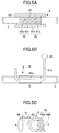
- Fig. 5 illustrates an example of a coil portion of the high-frequency induction heating device used in this embodiment.
- Fig. 5A is a front view
- Fig. 5B is a plan view
- Fig. 5C is a side view.
- a coil portion 6 as illustrated includes arm portions 61 that are extended from a high frequency power source 60 and a pair of upper and lower holding portions 62 that are connected to the arm portions 61 and support an upper surface portion and a lower surface portion of the stabilizer bar 2 to input high frequency.
- the holding portions 62 includes an upper holding portion 62a and a lower holding portion 62b that are positioned to face each other in an upper and lower direction.
- the arm portions 61 includes an upper arm portion 61a that is connected to an upper surface of the upper holding portion 62a and a lower arm portion 61b that is connected to a lower surface of the lower holding portion 62b.
- each of the upper holding portion 62a and the lower holding portion 62b of the holding portions 62 has a width substantially the same as that of the portion to be adhered 20 of the stabilizer bar 2, and has a curved shape that extends along an outer peripheral surface of the stabilizer bar 2.
- the portion to be adhered 20 of the stabilizer bar 2 can be uniformly heated.
- the portion to be adhered 20 of the stabilizer bar 2 is placed between the upper holding portion 62a and the lower holding portion 62b of the coil portion 6 and is held. Then, the high frequency power source 60 is operated while holding the portion to be adhered 20 to heat the portion to be adhered 20 of the stabilizer bar 2 by high-frequency induction heating.
- the heating temperature it is necessary to consider temperature at which a vulcanizing reaction occurs and temperature at which a coated film of the stabilizer bar 2 does not melt.
- the temperature at which an appropriate vulcanizing reaction is expected is greater than or equal to 180 °C and it is assumed that temperature at which the coated film of the stabilizer bar 2 of the embodiment melts is greater than or equal to 280 °C.
- the vulcanizing reaction occurs at 160 °C as temperature at which the vulcanizing reaction occurs.
- the portion to be adhered 20 of the stabilizer bar 2 is heated at temperature greater than or equal to 160 °C and less than 280 °C.
- This heating is continued until a center portion of the portion to be adhered 20 of the stabilizer bar 2 becomes the above described temperature, greater than 160 °C and less than 280 °C. This is because it is necessary for the portion to be adhered 20 of the stabilizer bar 2 to maintain the temperature that can cause the vulcanizing reaction to occur until adhering with the rubber bush 3, which will be explained later.
- heating time necessary to heat the center portion of the portion to be adhered 20 depends on the material or the diameter of the stabilizer bar 2, as an example, the heating time is about 60 seconds for a case of a stabilizer bar where epoxy polyester coating is used to coat and whose diameter is 15 mm or 35 mm. At this time, it is preferable that the temperature is increased to predetermined temperature within the above described range during the first 30 seconds, and the predetermined temperature is retained during the latter 30 seconds. Of course, the time may be less than or equal to 60 seconds, and time allocation of increasing and retaining may be appropriately varied.
- the center portion of the portion to be adhered 20 by heat high-frequency induction heating it is necessary to appropriately set frequency.
- the high-frequency induction heating current mostly flows at a heating surface to heat, and the center portion of the material is heated by heat conduction from the surface.
- the depth of penetration of the current inverses the frequency and the depth of penetration of the current becomes deeper with the lower frequency.
- heating is performed at the frequency of 1 kHz to 50 kHz.
- center temperature of greater than or equal to 200 °C can be maintained greater than or equal to 4 minutes when a stabilizer bar whose diameter is 35 mm is used and heated by setting the frequency as 45 kHz.
- a coated film performance for the case when the stabilizer bar 2 is heated within the above described ranges of the temperature and the time was measured by a salt spray test. Specifically, a cross cut is formed at the portion to be adhered of the stabilizer bar, and salt spray was continuously performed at the cross cut portion for 860 hours. As a result, at any temperature zones, poor appearance such as blistering, peeling of the coated film did not occur at a position near (3 mm) the cross cut portion. As the rubber bush 3 is fitted on the portion to be adhered 20 of the stabilizer bar 2 of the embodiment and the portion to be adhered 20 is not exposed, the coated film performance of the portion to be adhered 20 can be surely ensured.
- heating temperature range of greater than or equal to 160 °C and less than 280 °C the upper limit value may be arbitrarily varied based on the materials, the kind of coating, and the diameters of the stabilizer bar 2 and the rubber bush 3.
- the upper limit value it may be set at (upper limit) temperature at which the portion to be adhered 20 of the stabilizer bar 2 is not damaged, and temperature at which the rubber bush 3 can exert an adhesive performance.
- the damage here indicates melting or burning of coating, and lowering of remaining stress.
- the temperature at which the adhesive performance can be exerted means temperature at which the rubber bush 3 can appropriately perform vulcanizing adhesion.
- the lower limit value is also varied based on the diameter or the material of the stabilizer bar 2, it can be appropriately varied as long as minimum temperature at which the vulcanizing reaction is surely occurred is ensured.
- the operating time in the above described heating step is about 75 seconds in total including 60 seconds for heating time and 15 seconds for detaching the stabilizer bar 2 from the holding portions 62 of the high-frequency induction heating device.
- a fitting step is performed in which the hollow hole 33 of the rubber bush 3 at which the vulcanizing adhesive is coated is fitted on the portion to be adhered 20 of the stabilizer bar 2 heated in the heating step.
- the rubber bush 3 has a structure to be housed in (fitted by) the upper bracket member 4 and the lower bracket member 5.
- steps of a fitting step in which the rubber bush 3, the upper bracket member 4 and the lower bracket member 5 are fitted to (fitted on) the portion to be adhered 20 of the stabilizer bar 2 are explained with references to Fig. 6A to Fig. 6C .
- the upper bracket member 4 and the upper half portion 3A of the rubber bush 3 are placed in an inner side surface of a lower jig 81 that is provided at an upper surface of a base portion 71 of a clamping device 7.
- the inner side surface of the lower jig 81 is formed to have a shape that extends along an outer peripheral shape of the upper bracket member 4.
- the upper bracket member 4 is placed in the inner side surface of the lower jig 81, and the upper half portion 3A of the rubber bush 3 is placed on an inner side surface of the housing portion 41 of the upper bracket member 4. At this time, bolts 9 are inserted in bolt holes 42a of the upper bracket member 4, respectively.
- the heated portion to be adhered 20 of the stabilizer bar 2 is placed on the above described concave portion 30A of the upper half portion 3A of the rubber bush 3.
- lower half of the stabilizer bar 2 in the drawing contacts the concave portion 30A of the upper half portion 3A of the rubber bush 3 and upper half of the stabilizer bar 2 in the drawing is exposed.
- the concave portion 30B of the lower half portion 3B of the rubber bush 3 is fitted to the exposed upper half of the portion to be adhered 20 of the stabilizer bar 2.
- the outer peripheral surface of the portion to be adhered 20 of the stabilizer bar 2 contacts the surface 33a of the hollow hole 33 that is formed by the concave portions 30A and 30B of the upper half portion 3A and the lower half portion 3B, respectively, of the rubber bush 3.
- the lower bracket member 5 After fitting the rubber bush 3 on the portion to be adhered 20 of the stabilizer bar 2, the lower bracket member 5 is placed on the flat surface 32 of the rubber bush 3. At this time, the lower bracket member 5 is placed such that the above described bolts 9 are inserted in the bolt holes 52a of the flange portions 52, respectively. Then, the outer wall surface 31 of the rubber bush 3 is housed in the housing portion 41 of the upper bracket member 4 and the flat surface 32 of the rubber bush 3 is hosed in the housing portion 51 of the lower bracket member 5. Then, an upper jig 82 that fixes the fitting status of the members and compresses the rubber bush 3, is provided at a back surface side of the lower bracket member 5.
- the rubber bush 3 when fitting a rubber bush 3 provided with a single slit for attachment on the portion to be adhered 20 of the stabilizer bar 2, the rubber bush 3 may be fitted on the portion to be adhered 20 by expanding the slit. Thereafter, substantially similarly to the above described steps, the rubber bush 3 housing the stabilizer bar 2 is placed on an inside surface of the housing portion 41 of the upper bracket member 4, and the lower bracket member 5 is placed on the flat surface 32 of the rubber bush 3 to be fitted.
- a pressing portion 72 of the clamping device 7 is set on an upper surface of the upper jig 82 and is pressed. Then, the rubber bush 3 is clamped in a radial direction by the pressing portion 72 and the base portion 71 of the clamping device 7 and the rubber bush 3 can be fixed on the stabilizer bar 2.
- the pressing force for pressing the rubber bush 3 by the clamping device 7 is considerably higher than the pressing force (compressive force) by the jig.
- the pressing time and the pressing force pressing the rubber bush 3 by the clamping device 7 are set at an optimal condition in accordance with the material or the diameter of the rubber bush 3.
- the temperature of the portion to be adhered 20 of the stabilizer bar 2 when it is clamped by the clamping device 7 is retained at greater than or equal to 180 °C which is necessary for the appropriate vulcanizing reaction.
- the vulcanizing reaction crosslinking reaction between the surface 33a of the hollow hole 33 of the rubber bush 3 on which the vulcanizing adhesive is coated and the portion to be adhered 20 of the stabilizer bar 2 occurs and the rubber bush 3 and the portion to be adhered 20 of the stabilizer bar 2 can be surely adhered by vulcanizing adhesion.
- the upper jig 82 is appropriately detached and the nuts 90 are screwed to the bolts 9 that are inserted in the bolt holes 42a and 52a of the upper bracket member 4 and the lower bracket member 5 to be fastened, respectively.
- adhesion accuracy can be increased.
- the fitting step and the adhering step can be performed for a preceding stabilizer bar 2 that is already heated during 75 seconds while the stabilizer bar 2 is heated (including detaching the stabilizer bar 2).
- the heating step and the adhering step are continuously performed at the same place, other tasks cannot be performed while performing the fitting step to the adhering step.
- the heating step is performed separately as a preceding step, the total manufacturing time can be shortened by performing the fitting step or the adhering step for another preceding stabilizer bar 2 while performing the heating step.
- the rubber bush provided stabilizer bar 1 as illustrated in Fig. 3 is completed.
- the leaving time in the leaving step varies based on the material or the diameter of the stabilizer bar 2 or the rubber bush 3, the heating temperature or the like, but becomes shorter as the heating temperature is lower and the diameter is smaller.
- the rubber bush provided stabilizer bar 1 manufactured by each of the above described steps is fixed to the frame portion FR of the vehicle by a mounting member that is separately provided at the frame portion FR thereafter.
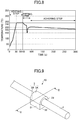
- Fig. 8 is a graph illustrating variation of temperature of the portion to be adhered 20 of the stabilizer bar 2 from the heating step to the adhering step when performing the above described method of manufacturing the rubber bush provided stabilizer bar 1.
- the stabilizer bar 2 whose diameter was 35 mm was used and the temperature at a surface portion of the portion to be adhered 20 was measured.
- heating temperature at the heating step was 240 °C and the heating time was 60 seconds. The temperature was increased to 240 °C during the first 30 seconds, and the temperature was retained at 240 °C during the latter 30 seconds.
- the temperature of a surface portion of the portion to be adhered 20 was temporarily drastically decreased to 150 °C.
- the center portion of the portion to be adhered 20 was heated in the heating step.
- heat conduction occurs from the center portion to the surface portion and the temperature of the surface portion immediately increased to 200 °C.
- the temperature of the portion to be adhered 20 was kept at greater than or equal to 180 °C (range between 200 °C to 180 °C) necessary for an appropriate vulcanizing reaction for long time.
- a vulcanizing reaction occurs between the surface 33a of the rubber bush 3 at which the vulcanizing adhesive is coated and the portion to be adhered 20 of the stabilizer bar 2 and both of them can be surely adhered by vulcanizing adhesion.
- the portion to be adhered 20 of the stabilizer bar 2 is previously heated (heating step). Thereafter, the rubber bush 3 at which the vulcanizing adhesive is coated is fitted on the portion to be adhered 20 (fitting step), and they are adhered by pressing (adhering step).
- the heating step of the stabilizer bar 2 is separately provided prior to other steps, it is possible to perform the fitting step or the adhering step for the preceding already heated stabilizer bar 2 while heating the next stabilizer bar 2, so that the total manufacturing time can be shortened and the working efficiency can be improved and energy saving effect can be obtained.
- the heating time can be suppressed to the minimum, and the heating temperature can be set at temperature at which the coating of the stabilizer bar 2 does not melt and at which the vulcanizing reaction can surely occur.
- the heating temperature can be set at temperature at which the coating of the stabilizer bar 2 does not melt and at which the vulcanizing reaction can surely occur.
- a method of directly heating the portion to be adhered 20 of the stabilizer bar 2 to appropriately perform the temperature management of the portion to be adhered 20.
- the portion to be adhered 20 is exposed right before fitting the rubber bush 3 or various bracket members, whether the temperature of the portion to be adhered 20 is increased to the predetermined temperature can be surely monitored. Then, a temperature management in which temperature drop from the completion of heating to the adhering step is considered can be performed and a high adhesion accuracy can be stably obtained.
- the stabilizer bar is pre heated, the following effects can be obtained compared with a conventional case.
- the stabilizer bar is heated later, as described above, it is necessary to heat the stabilizer bar at higher temperature, such as greater than or equal to 300 °C, compared with the pre-heating case. If the coated stabilizer bar is heated at greater than or equal to 300 °C, clouding may occur at the coated surface of the heated position.
- the manufacturing method of the embodiment is pre-heating, it is possible to heat at a lower temperature zone compared with the post-heating case, and the problem that the poor appearance such as clouding or the like of the coated surface occurs near the heated position can be solved.
- Fig. 9 is a perspective view of the rubber bush provided stabilizer bar 10 of the second embodiment.
- Fig. 10 is a cross-sectional view taken along line II-II of Fig. 9 .
- the rubber bush provided stabilizer bar 10 of the embodiment basically has the same structure as the rubber bush provided stabilizer bar 1 explained in the first embodiment.
- the upper bracket member 4 and the lower bracket member 5 are not fitted on the outer peripheral surface of the rubber bush 3. In other words, it is structured only by the stabilizer bar 2 and the rubber bush 3. Thus, as the structures of the stabilizer bar 2 and the rubber bush 3 and their adhesion structure are the same as those already explained in the first embodiment, and are not repeated.
- the reason that the upper bracket member 4 and the lower bracket member 5 are not used is that the adhesion accuracy between the rubber bush 3 and the stabilizer bar 2 are stably high, as described in the first embodiment.
- it is not essential to press and hold the rubber bush 3 by the bracket members, and it is possible to reduce the number of members. With this configuration, the working efficiency can be further improved, the cost can be further reduced, and the energy saving effect can be further improved.
- the method of manufacturing the rubber bush provided stabilizer bar 10 of the embodiment overlaps the method of manufacturing explained in the first embodiment for many points. Thus, different points are mainly explained in the following.
- Chemlok manufactured by LORD Corporation is coated on the surface 33a of the hollow hole 33 of the vulcanized rubber bush 3 as a vulcanizing adhesive. In this coating step, it is preferable that the vulcanizing adhesive is coated for a plurality of times and a plurality of adhesive layers are formed.
- the portion to be adhered 20 of the stabilizer bar 2 is heated using a high-frequency induction heating device by high-frequency induction heating.
- the heating temperature, the heating time and the frequency in the heating step are the same as those explained in the first embodiment and explanations are not repeated. Further, the method of heating by the high-frequency induction heating device is also the same.
- the rubber bush 3 of the first embodiment has a structure being housed in (fitted on by) the upper bracket member 4 and the lower bracket member 5, as illustrated in Fig. 9 or the like, nothing is fitted on the outer peripheral surface of the rubber bush 3 in this embodiment.
- the fitting step of the embodiment is different from that of the first embodiment in that an upper jig and a lower jig that are provided to press the rubber bush 3 after fitting the rubber bush 3 on the portion to be adhered 20 of the stabilizer bar 2.
- the upper half portion 3A of the rubber bush 3 is placed in a concave portion 810a provided at an inner side surface of a lower jig 810 that is provided at an upper surface of the base portion 71 of the clamping device 7.
- the heated portion to be adhered 20 of the stabilizer bar 2 is placed on the concave portion 30A of the above described upper half portion 3A of the rubber bush 3.
- a lower half of the stabilizer bar 2 contacts the concave portion 30A of the upper half portion 3A of the rubber bush 3 and an upper half is exposed, in the drawing.
- the concave portion 30B of the lower half portion 3B of the rubber bush 3 is fitted to the exposed upper half portion of the to be adhered 20 of the stabilizer bar 2.
- the outer peripheral surface of the portion to be adhered 20 of the stabilizer bar 2 comes to be in contact with the surface 33a of the hollow hole 33 that is formed by the concave portions 30A and 30B of the upper half portion 3A and the lower half portion 3B of the rubber bush 3, respectively.
- an upper jig 820 is placed on the flat surface 32 of the rubber bush 3.
- the upper jig 820 is provided with a U-shaped concave portion 820a at an inner side surface that houses a lower portion of the outer wall surface 31 and the flat surface 32 of the lower half portion 3B of the rubber bush 3.
- the concave portion 820a of the upper jig 820 is fitted in a status of housing the lower portion of the outer wall surface 31 and the flat surface 32 of the rubber bush 3.
- the lower jig 810 and the upper jig 820 fix the rubber bush 3 in a compressed status by screwing, a clamping member or the like.
- the pressing portion 72 of the clamping device 7 is set at the upper surface of the upper jig 820 and pressed under a status that the upper jig 820 and the lower jig 810 are fitted on the outer peripheral surface of the rubber bush 3 in which the stabilizer bar 2 is housed. Then, the rubber bush 3 is clamped in the radial direction by the upper jig 820 and the lower jig 810 and the rubber bush 3 and the stabilizer bar 2 are rigidly adhered.
- the pressing time and the pressing force pressing the rubber bush 3 by the clamping device 7 are set at an optimal condition in accordance with the material or the diameter of the rubber bush 3.
- the rubber bush 3 of the embodiment has a structure in which nothing is fitted on its outer peripheral surface, it is pressed at a condition by which a sufficient fixing strength is obtained.
- the rubber bush provided stabilizer bar 10 is completed as illustrated in Fig. 12B after the rubber bush provided stabilizer bar 10 on which the rubber bush 3 is adhered by the adhering step is detached from the clamping device 7, retained at a clamping status by the above described upper and lower jigs (810, 820) for about 30 minutes, and detaching the upper jig 820 and the lower jig 810 from the rubber bush 3.
- the rubber bush provided stabilizer bar 10 of the embodiment is fixed to the frame portion FR of the vehicle by a separately provided mounting bracket.
- the rubber bush provided stabilizer bar of the second embodiment it is possible to reduce the number of members to the minimum, further improve the working efficiency, further reduce the cost and further improve energy saving effect compared with the first embodiment. Further, similar to the first embodiment, poor appearance of the stabilizer bar 2 can be prevented, and the high adhesion accuracy can be stably obtained by appropriately performing a temperature management of the portion to be adhered 20.
Landscapes
- Engineering & Computer Science (AREA)
- Mechanical Engineering (AREA)
- Physics & Mathematics (AREA)
- General Engineering & Computer Science (AREA)
- Chemical & Material Sciences (AREA)
- Thermal Sciences (AREA)
- Aviation & Aerospace Engineering (AREA)
- Acoustics & Sound (AREA)
- Combustion & Propulsion (AREA)
- Chemical Kinetics & Catalysis (AREA)
- General Chemical & Material Sciences (AREA)
- Vehicle Body Suspensions (AREA)
- Springs (AREA)
- Lining Or Joining Of Plastics Or The Like (AREA)
- Vibration Prevention Devices (AREA)
Abstract
Description
- The present invention relates to a method of manufacturing a rubber bush provided stabilizer bar and a rubber bush provided stabilizer bar.
- For a vehicle such as an automobile, a rubber bush provided stabilizer bar (anti-roll bar) is connected to stabilize the position of the vehicle. The stabilizer bar is a member that mainly suppresses the body roll of the vehicle (rotational motion around a back and front direction of the vehicle body as an axis) using torsion toque. The rubber bush is attached between the stabilizer bar and the vehicle body and has a function to support the vehicle body by dampening transferring of the oscillation that is input to the stabilizer bar due to a condition of a road surface to the vehicle body, and flexibly following the movement of the stabilizer bar.
- Conventionally, the rubber bush provided stabilizer bar is mainly an unbonded type in which the stabilizer bar is only inserted in the rubber bush. However, the unbonded type has a problem in that strange noises are generated or positional shift between the stabilizer bar and the rubber bush occurs.
- In view of the above described problem, a technique is known in which a rubber bush is adhered to a stabilizer bar by vulcanizing adhesion. For example, a rubber bush, provided with a centrum at which a vulcanizing adhesive (cure adhesive) is coated, is fitted on a portion to be adhered of the stabilizer bar. Then, portions of the stabilizer bar that are positioned outer side of the fitted position are heated by high-frequency induction heating to heat the portion to be adhered by heat conduction and cause a vulcanizing reaction so that the rubber bush and the stabilizer bar are adhered (see
Patent Document 1, for example). - [Patent Document 1] Japanese Laid-open Patent Publication No.
2006-290313 - It is said that in order to cause an appropriate vulcanizing reaction at the portion to be adhered of the stabilizer bar within a short period (about 30 seconds to 5 minutes), it is necessary to heat at greater than or equal to 180 °C. In the above described technique, the portion to be adhered of the stabilizer bar is heated from the both outer side portions of the fitted rubber bush by heat conduction. Thus, in order to heat the portion to be adhered at greater than or equal to 180 °C, it is necessary to heat the both outer side portions of the rubber bush to be higher than the portion to be adhered such as 360 °C or the like, for example, or it is necessary to heat it at greater than or equal to 180 °C for a long period.
- However, if the stabilizer bar is heated by high heat, poor appearance may occur such as clouding may occur at a coated surface of the heated position, or the coated film is damaged as being melted. Further, if it is heated for a long period, working efficiency is lowered and is not economic.
- Adhesion accuracy between the rubber bush and the stabilizer bar depends on an appropriate temperature management of the portion to be adhered. However, according to the conventional technique, as the portion to be adhered is heated from both outer side portions by heat conduction, the temperature management is difficult because it is necessary to consider influences of efficiency of heat transfer, heat dissipation or the like. Thus, there is a possibility that the adhesion accuracy may vary.
- The present invention is made in light of the above problems, and provides a method of manufacturing a rubber bush provided stabilizer bar capable of preventing poor appearance of the stabilizer bar and lowering of working efficiency, and stably obtaining high adhesion accuracy by appropriately performing a temperature management of a portion to be adhered.
- According to an embodiment, there is provided a method of manufacturing a rubber bush provided stabilizer bar by adhering a tubular shape rubber bush provided with a vulcanized centrum on a portion to be adhered of a stabilizer bar, the method including: a coating step of coating a vulcanizing adhesive at a surface of a centrum of the rubber bush; a heating step of heating the portion to be adhered of the stabilizer bar; a fitting step of fitting the centrum of the rubber bush at which the vulcanizing adhesive is coated on the heated portion to be adhered of the stabilizer bar; and an adhering step of clamping the rubber bush in a radial direction by a clamping device to adhere the rubber bush on the portion to be adhered of the stabilizer bar.
- According to the invention, a method of manufacturing a rubber bush provided stabilizer bar can be provided capable of preventing poor appearance of the stabilizer bar and lowering of working efficiency, and stably obtaining high adhesion accuracy by appropriately performing a temperature management of a portion to be adhered.
-
-
Fig. 1 is a perspective view illustrating a rubber bush provided stabilizer bar of a first embodiment and suspensions of front wheels of a vehicle; -
Fig. 2 is an exploded perspective view of the rubber bush provided stabilizer bar of the first embodiment; -
Fig. 3 is a perspective view illustrating the entirety of the rubber bush provided stabilizer bar of the first embodiment; -
Fig. 4 is a cross-sectional view taken along line I-IFig. 3 ; -
Fig. 5A is a front view illustrating an example of a coil portion of a high-frequency induction heating device used in a heating step; -
Fig. 5B is a plan view illustrating an example of the coil portion of the high-frequency induction heating device used in the heating step; -
Fig. 5C is a side view illustrating an example of the coil portion of the high-frequency induction heating device used in the heating step; -
Fig. 6A is a view (1) for explaining steps of a fitting step in which a rubber bush is fitted on a portion to be adhered of the stabilizer bar; -
Fig. 6B is a view (2) for explaining the steps of the fitting step in which the rubber bush is fitted on the portion to be adhered of the stabilizer bar; -
Fig. 6C is a view (3) for explaining the steps of the fitting step in which the rubber bush is fitted on the portion to be adhered of the stabilizer bar; -
Fig. 7A is a view (1) for explaining steps from an adhering step in which the stabilizer bar and the rubber bush are adhered, to a leaving step; -
Fig. 7B is a view (2) for explaining the steps from the adhering step in which the stabilizer bar and the rubber bush are adhered, to the leaving step; -
Fig. 7C is a view (3) for explaining the steps from the adhering step in which the stabilizer bar and the rubber bush are adhered, to the leaving step; -
Fig. 8 is a graph illustrating variation of temperature of the stabilizer bar from the heating step to the adhering step; -
Fig. 9 is a perspective view illustrating the entirety of a rubber bush provided stabilizer bar of a second embodiment; -
Fig. 10 is a cross-sectional view taken along line II-II ofFig. 9 ; -
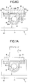
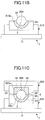
Fig. 11A is a view (1) for explaining steps of a fitting step in which a rubber bush is fitted on a portion to be adhered of the stabilizer bar; -
Fig. 11B is a view (2) for explaining the steps of the fitting step in which the rubber bush is fitted on the portion to be adhered of the stabilizer bar; -
Fig. 11C is a view (3) for explaining the steps of the fitting step in which the rubber bush is fitted on the portion to be adhered of the stabilizer bar; -
Fig. 12A is a view (1) for explaining steps from an adhering step in which the stabilizer bar and the rubber bush are adhered, to a leaving step; and -
Fig. 12B is a view (2) for explaining the steps from the adhering step in which the stabilizer bar and the rubber bush are adhered, to the leaving step. - Next, embodiments of a method of manufacturing a rubber bush provided stabilizer bar (a stabilizer bar provided with a rubber bush) and a rubber bush provided stabilizer bar of the invention are explained. In the drawings, the same components are given the same reference numerals, and explanations are simplified or not repeated. The drawings are not purposed to indicate relative ratio of a member or between members. Thus, specific sizes of the members may be respectively determined by those skilled in the art according to the following non limiting embodiments.
- The structure of a rubber bush provided
stabilizer bar 1 of the first embodiment is explained with reference toFig. 1 to Fig. 4 .Fig. 1 is a perspective view illustrating the rubber bush providedstabilizer bar 1 of the first embodiment and suspensions k of front wheels of a vehicle.Fig. 2 is an exploded perspective view illustrating the structure of the rubber bush providedstabilizer bar 1.Fig. 3 is a perspective view illustrating the entirety of the rubber bush providedstabilizer bar 1.Fig. 4 is a cross-sectional view ofFig. 3 taken along line I-I. - As illustrated in
Fig. 1 , the rubber bush providedstabilizer bar 1 includes astabilizer bar 2 composed of a metal solid member, andrubber bushes 3 that fix thestabilizer bar 2 to a frame portion FR of a vehicle body. - The
stabilizer bar 2 includes atorsion portion 21 that is bridged in a width direction X of the vehicle body,shoulder portions 22 that are positioned at both ends of thetorsion portion 21, respectively, andarm portions 23 that extend from theshoulder portions 22, respectively, in a back and front direction Z of the vehicle body. Thestabilizer bar 2 is formed such that its entirety has a substantially U shape. Further, link members R are provided at front end portions of thearm portions 23 to be connected with acting portions of the suspensions k, respectively. It is assumed that inner side positions of the left andright shoulder portions 22 of thestabilizer bar 2 are portions to be adhered 20 (seeFig. 2 ) on which therubber bushes 3 are adhered, respectively. - The surface of the above described
stabilizer bar 2 is coated by an epoxy or epoxypolyester coating by cationic electrodeposition coating or powder coating. - Here, conventionally, a problem exists in that when the coated position is heated at greater than or equal to 300 °C, clouding or the like is generated at the coated surface to cause poor appearance. As will be explained later, according to the method of manufacturing the rubber bush provided stabilizer bar of the embodiment, a heating step of the stabilizer bar is separately performed as a preceding step, it is possible to heat the stabilizer bar at a lower temperature zone compared with conventional cases and generation of poor appearance at the heated position can be prevented.
- As illustrated in
Fig. 2 to Fig. 4 , the rubber bush providedstabilizer bar 1 of the embodiment has a structure in which therubber bush 3 is fitted on the portion to be adhered 20 of thestabilizer bar 2, and anupper bracket member 4 and alower bracket member 5 are fitted on an outer peripheral surface of each of therubber bush 3. - The
rubber bush 3 is formed to have a tubular shape including a U shapedouter wall surface 31 and a linearflat surface 32 that is continuously formed from both lower end portions of theouter wall surface 31. Further, therubber bush 3 is provided with a hollow hole 33 (corresponding to a centrum) at a substantially center position for housing the portion to be adhered 20 of thestabilizer bar 2. - The
rubber bush 3 as illustrated is divided into anupper half portion 3A and alower half portion 3B, and thehollow hole 33 is formed by fitting semicircular shapedconcave portions upper half portion 3A and thelower half portion 3B, respectively. - A vulcanizing adhesive is coated at a
surface 33a of the above describedhollow hole 33, and is adhered with the portion to be adhered 20 of thestabilizer bar 2 by vulcanizing adhesion. The material of therubber bush 3 is a rubber, and a synthetic rubber obtained by synthesizing a natural rubber (NR) and a butadiene rubber (BR) is used, for example, and which is previously vulcanized. The material of the synthetic rubber is not limited to the above described one and other materials may be used. - The
upper bracket member 4 includes ahousing portion 41 that houses a U shapedouter wall surface 31 of therubber bush 3, andflange portions 42 that extend from both ends of thehousing portion 41 in a horizontal direction and are provided withbolt holes 42a, respectively. Thehousing portion 41 is formed to have a U shape that extends along theouter wall surface 31 of therubber bush 3. - The
lower bracket member 5 includes ahousing portion 51 that houses theflat surface 32 of therubber bush 3, andflange portions 52 that extend from both ends of thehousing portion 51 in a horizontal direction and are provided withbolt holes 52a, respectively. Although thehousing portion 51 and theflange portions 52 are provided to form a continuous horizontal surface, this is not limited so. Thehousing portion 51 and theflange portions 52 may be appropriately designed in accordance with the shape of therubber bush 3. It is preferable that the materials of theupper bracket member 4 and thelower bracket member 5 are metal such as an aluminum alloy or the like. - In the rubber bush provided
stabilizer bar 1 of the embodiment, under a status that the above describedupper bracket member 4 houses theouter wall surface 31 of therubber bush 3 and thelower bracket member 5 houses theflat surface 32 of therubber bush 3,bolt holes flange portions bolts 9 and the nuts 90. It is apparent that theupper bracket member 4 and thelower bracket member 5 are not only bonded by thebolts 9 andnuts 90 but may be bonded by other bonding methods that are generally adopted such as bonding by pins or the like. Further, although the illustratedrubber bush 3 is divided into theupper half portion 3A and thelower half portion 3B, this is not limited so. Therubber bush 3 may be integrally formed one in which a single slit extending along a radial direction and an axis direction is formed. - Next, a method of manufacturing the rubber bush provided
stabilizer bar 1 is explained. - Chemlok (registered trademark) manufactured by LORD Corporation is coated on the
surface 33a of thehollow hole 33 of the vulcanizedrubber bush 3 as a vulcanizing adhesive. Specifically, it is preferable that Chemlok 6100 is undercoated, and thereafter, Chemlok 205 is over coated thereon. - Next, the portion to be adhered 20 of the
stabilizer bar 2 is heated using a high-frequency induction heating device by high-frequency induction heating.Fig. 5 illustrates an example of a coil portion of the high-frequency induction heating device used in this embodiment.Fig. 5A is a front view,Fig. 5B is a plan view andFig. 5C is a side view. - A
coil portion 6 as illustrated includesarm portions 61 that are extended from a highfrequency power source 60 and a pair of upper andlower holding portions 62 that are connected to thearm portions 61 and support an upper surface portion and a lower surface portion of thestabilizer bar 2 to input high frequency. The holdingportions 62 includes anupper holding portion 62a and alower holding portion 62b that are positioned to face each other in an upper and lower direction. Thearm portions 61 includes anupper arm portion 61a that is connected to an upper surface of theupper holding portion 62a and alower arm portion 61b that is connected to a lower surface of thelower holding portion 62b. Theupper arm portion 61a and thelower arm portion 62b are connected by a connectingmember 63 at a back side B (highfrequency power source 60 side) of thecoil portion 6 so that members of thearm portions 61 do not exist at a front side F of thecoil portion 6. Thus, it is easy to place thestabilizer bar 2 at the holdingportions 62, and it is easy to detach as well. Further, each of theupper holding portion 62a and thelower holding portion 62b of the holdingportions 62 has a width substantially the same as that of the portion to be adhered 20 of thestabilizer bar 2, and has a curved shape that extends along an outer peripheral surface of thestabilizer bar 2. Thus, the portion to be adhered 20 of thestabilizer bar 2 can be uniformly heated. - Hereinafter, a specific method for heating the portion to be adhered 20 of the
stabilizer bar 2 using the abovestructured coil portion 6 by high-frequency induction heating is explained. - First, the portion to be adhered 20 of the
stabilizer bar 2 is placed between theupper holding portion 62a and thelower holding portion 62b of thecoil portion 6 and is held. Then, the highfrequency power source 60 is operated while holding the portion to be adhered 20 to heat the portion to be adhered 20 of thestabilizer bar 2 by high-frequency induction heating. For the heating temperature, it is necessary to consider temperature at which a vulcanizing reaction occurs and temperature at which a coated film of thestabilizer bar 2 does not melt. The temperature at which an appropriate vulcanizing reaction is expected is greater than or equal to 180 °C and it is assumed that temperature at which the coated film of thestabilizer bar 2 of the embodiment melts is greater than or equal to 280 °C. Here, it is confirmed that, for a case in which the diameter of thestabilizer bar 2 is 25 mm, the vulcanizing reaction occurs at 160 °C as temperature at which the vulcanizing reaction occurs. - Thus, in this embodiment, the portion to be adhered 20 of the
stabilizer bar 2 is heated at temperature greater than or equal to 160 °C and less than 280 °C. - This heating is continued until a center portion of the portion to be adhered 20 of the
stabilizer bar 2 becomes the above described temperature, greater than 160 °C and less than 280 °C. This is because it is necessary for the portion to be adhered 20 of thestabilizer bar 2 to maintain the temperature that can cause the vulcanizing reaction to occur until adhering with therubber bush 3, which will be explained later. - Although heating time necessary to heat the center portion of the portion to be adhered 20 depends on the material or the diameter of the
stabilizer bar 2, as an example, the heating time is about 60 seconds for a case of a stabilizer bar where epoxy polyester coating is used to coat and whose diameter is 15 mm or 35 mm. At this time, it is preferable that the temperature is increased to predetermined temperature within the above described range during the first 30 seconds, and the predetermined temperature is retained during the latter 30 seconds. Of course, the time may be less than or equal to 60 seconds, and time allocation of increasing and retaining may be appropriately varied. - Further, in order to heat the center portion of the portion to be adhered 20 by heat high-frequency induction heating, it is necessary to appropriately set frequency. In the high-frequency induction heating, current mostly flows at a heating surface to heat, and the center portion of the material is heated by heat conduction from the surface. Thus, the deeper the depth of penetration of the current is, the center portion can be also efficiently heated. The depth of penetration of the current inverses the frequency and the depth of penetration of the current becomes deeper with the lower frequency. In this embodiment, heating is performed at the frequency of 1 kHz to 50 kHz.
- It is confirmed that the center temperature of greater than or equal to 200 °C can be maintained greater than or equal to 4 minutes when a stabilizer bar whose diameter is 35 mm is used and heated by setting the frequency as 45 kHz.
- Further, as a result of measuring remaining stress when the
stabilizer bar 2 is heated within the above described ranges of the temperature and the time, it is confirmed that there is no problem in quality of the remaining stress as there is no difference between the remaining stress at any temperature zones compared with astabilizer bar 2 that is not heated. - Further, a coated film performance for the case when the
stabilizer bar 2 is heated within the above described ranges of the temperature and the time was measured by a salt spray test. Specifically, a cross cut is formed at the portion to be adhered of the stabilizer bar, and salt spray was continuously performed at the cross cut portion for 860 hours. As a result, at any temperature zones, poor appearance such as blistering, peeling of the coated film did not occur at a position near (3 mm) the cross cut portion. As therubber bush 3 is fitted on the portion to be adhered 20 of thestabilizer bar 2 of the embodiment and the portion to be adhered 20 is not exposed, the coated film performance of the portion to be adhered 20 can be surely ensured. - For the above described heating temperature, temperature range of greater than or equal to 160 °C and less than 280 °C, the upper limit value may be arbitrarily varied based on the materials, the kind of coating, and the diameters of the
stabilizer bar 2 and therubber bush 3. - As a condition of the upper limit value, it may be set at (upper limit) temperature at which the portion to be adhered 20 of the
stabilizer bar 2 is not damaged, and temperature at which therubber bush 3 can exert an adhesive performance. The damage here indicates melting or burning of coating, and lowering of remaining stress. Further, the temperature at which the adhesive performance can be exerted means temperature at which therubber bush 3 can appropriately perform vulcanizing adhesion. As the lower limit value is also varied based on the diameter or the material of thestabilizer bar 2, it can be appropriately varied as long as minimum temperature at which the vulcanizing reaction is surely occurred is ensured. - Here, the operating time in the above described heating step is about 75 seconds in total including 60 seconds for heating time and 15 seconds for detaching the
stabilizer bar 2 from the holdingportions 62 of the high-frequency induction heating device. - Next, a fitting step is performed in which the
hollow hole 33 of therubber bush 3 at which the vulcanizing adhesive is coated is fitted on the portion to be adhered 20 of thestabilizer bar 2 heated in the heating step. - In this embodiment, the
rubber bush 3 has a structure to be housed in (fitted by) theupper bracket member 4 and thelower bracket member 5. Thus, hereinafter, steps of a fitting step in which therubber bush 3, theupper bracket member 4 and thelower bracket member 5 are fitted to (fitted on) the portion to be adhered 20 of thestabilizer bar 2 are explained with references toFig. 6A to Fig. 6C . - First, as illustrated in
Fig. 6A , theupper bracket member 4 and theupper half portion 3A of therubber bush 3 are placed in an inner side surface of alower jig 81 that is provided at an upper surface of abase portion 71 of aclamping device 7. Here, the inner side surface of thelower jig 81 is formed to have a shape that extends along an outer peripheral shape of theupper bracket member 4. - Specifically, first, the
upper bracket member 4 is placed in the inner side surface of thelower jig 81, and theupper half portion 3A of therubber bush 3 is placed on an inner side surface of thehousing portion 41 of theupper bracket member 4. At this time,bolts 9 are inserted inbolt holes 42a of theupper bracket member 4, respectively. - Next, as illustrated in
Fig. 6B , the heated portion to be adhered 20 of thestabilizer bar 2 is placed on the above describedconcave portion 30A of theupper half portion 3A of therubber bush 3. At this time, lower half of thestabilizer bar 2 in the drawing contacts theconcave portion 30A of theupper half portion 3A of therubber bush 3 and upper half of thestabilizer bar 2 in the drawing is exposed. - Then, as illustrated in
Fig. 6C , theconcave portion 30B of thelower half portion 3B of therubber bush 3 is fitted to the exposed upper half of the portion to be adhered 20 of thestabilizer bar 2. Thus, at this time, the outer peripheral surface of the portion to be adhered 20 of thestabilizer bar 2 contacts thesurface 33a of thehollow hole 33 that is formed by theconcave portions upper half portion 3A and thelower half portion 3B, respectively, of therubber bush 3. - After fitting the
rubber bush 3 on the portion to be adhered 20 of thestabilizer bar 2, thelower bracket member 5 is placed on theflat surface 32 of therubber bush 3. At this time, thelower bracket member 5 is placed such that the above describedbolts 9 are inserted in the bolt holes 52a of theflange portions 52, respectively. Then, theouter wall surface 31 of therubber bush 3 is housed in thehousing portion 41 of theupper bracket member 4 and theflat surface 32 of therubber bush 3 is hosed in thehousing portion 51 of thelower bracket member 5. Then, anupper jig 82 that fixes the fitting status of the members and compresses therubber bush 3, is provided at a back surface side of thelower bracket member 5. - The above described fitting step with reference to
Fig. 6A to Fig. 6C is performed when therubber bush 3 is half cut. Thus, the fitting step is not limited to the structure illustrated in the drawings. - Although not illustrated in the drawings, when fitting a
rubber bush 3 provided with a single slit for attachment on the portion to be adhered 20 of thestabilizer bar 2, therubber bush 3 may be fitted on the portion to be adhered 20 by expanding the slit. Thereafter, substantially similarly to the above described steps, therubber bush 3 housing thestabilizer bar 2 is placed on an inside surface of thehousing portion 41 of theupper bracket member 4, and thelower bracket member 5 is placed on theflat surface 32 of therubber bush 3 to be fitted. - Next, an adhering step in which the
rubber bush 3 housing thestabilizer bar 2 is clamped to adhere therubber bush 3 and thestabilizer bar 2 is performed. Steps of the adhering step are explained with reference toFig. 7A andFig. 7B . - As illustrated in
Fig. 7A , under a status that therubber bush 3, theupper bracket member 4 and thelower bracket member 5 are fitted on the portion to be adhered 20 of thestabilizer bar 2, apressing portion 72 of theclamping device 7 is set on an upper surface of theupper jig 82 and is pressed. Then, therubber bush 3 is clamped in a radial direction by thepressing portion 72 and thebase portion 71 of theclamping device 7 and therubber bush 3 can be fixed on thestabilizer bar 2. Thus, the pressing force for pressing therubber bush 3 by theclamping device 7 is considerably higher than the pressing force (compressive force) by the jig. Here, the pressing time and the pressing force pressing therubber bush 3 by theclamping device 7 are set at an optimal condition in accordance with the material or the diameter of therubber bush 3. - As described above, the temperature of the portion to be adhered 20 of the
stabilizer bar 2 when it is clamped by theclamping device 7 is retained at greater than or equal to 180 °C which is necessary for the appropriate vulcanizing reaction. Thus, the vulcanizing reaction (crosslinking reaction) between thesurface 33a of thehollow hole 33 of therubber bush 3 on which the vulcanizing adhesive is coated and the portion to be adhered 20 of thestabilizer bar 2 occurs and therubber bush 3 and the portion to be adhered 20 of thestabilizer bar 2 can be surely adhered by vulcanizing adhesion. - Then, as illustrated in
Fig. 7B , theupper jig 82 is appropriately detached and the nuts 90 are screwed to thebolts 9 that are inserted in the bolt holes 42a and 52a of theupper bracket member 4 and thelower bracket member 5 to be fastened, respectively. As described above, by retaining a clamping status in the radial direction to therubber bush 3 by thebolts 9 and thenuts 9, adhesion accuracy can be increased. - Here, when manufacturing a plurality of rubber bush provided
stabilizer bars 1 by heating the plurality ofstabilizer bars 2 in order, when assuming that the pressing time in the adhering step is one minute, for example, the fitting step and the adhering step can be performed for a precedingstabilizer bar 2 that is already heated during 75 seconds while thestabilizer bar 2 is heated (including detaching the stabilizer bar 2). Here, in the conventional example, as the fitting step, the heating step and the adhering step are continuously performed at the same place, other tasks cannot be performed while performing the fitting step to the adhering step. - However, as described above, according to the manufacturing method of the embodiment, the heating step is performed separately as a preceding step, the total manufacturing time can be shortened by performing the fitting step or the adhering step for another preceding
stabilizer bar 2 while performing the heating step. - Next, as illustrated in
Fig. 7C , by detaching the rubber bush providedstabilizer bar 1 in which therubber bush 3 is fitted in the adhering step from theclamping device 7 and the lower jig 81 (upper jig 82), leaving it for about 30 minutes under a status being fastened by thebolts 9 and the nuts 90, and naturally cooling, the rubber bush providedstabilizer bar 1 as illustrated inFig. 3 is completed. The leaving time in the leaving step varies based on the material or the diameter of thestabilizer bar 2 or therubber bush 3, the heating temperature or the like, but becomes shorter as the heating temperature is lower and the diameter is smaller. - The rubber bush provided
stabilizer bar 1 manufactured by each of the above described steps is fixed to the frame portion FR of the vehicle by a mounting member that is separately provided at the frame portion FR thereafter. -
Fig. 8 is a graph illustrating variation of temperature of the portion to be adhered 20 of thestabilizer bar 2 from the heating step to the adhering step when performing the above described method of manufacturing the rubber bush providedstabilizer bar 1. Here, thestabilizer bar 2 whose diameter was 35 mm was used and the temperature at a surface portion of the portion to be adhered 20 was measured. As can be understood from the drawing, heating temperature at the heating step was 240 °C and the heating time was 60 seconds. The temperature was increased to 240 °C during the first 30 seconds, and the temperature was retained at 240 °C during the latter 30 seconds. - Thereafter, in the fitting step, as the
rubber bush 3 and the upper and lower bracket members whose temperatures were low absorbed heat, the temperature of a surface portion of the portion to be adhered 20 was temporarily drastically decreased to 150 °C. However, the center portion of the portion to be adhered 20 was heated in the heating step. Thus, heat conduction occurs from the center portion to the surface portion and the temperature of the surface portion immediately increased to 200 °C. Then, in the adhering step, the temperature of the portion to be adhered 20 was kept at greater than or equal to 180 °C (range between 200 °C to 180 °C) necessary for an appropriate vulcanizing reaction for long time. - Thus, in the adhering step, a vulcanizing reaction occurs between the
surface 33a of therubber bush 3 at which the vulcanizing adhesive is coated and the portion to be adhered 20 of thestabilizer bar 2 and both of them can be surely adhered by vulcanizing adhesion. - As described above, in the method of manufacturing the rubber bush provided
stabilizer bar 1, the portion to be adhered 20 of thestabilizer bar 2 is previously heated (heating step). Thereafter, therubber bush 3 at which the vulcanizing adhesive is coated is fitted on the portion to be adhered 20 (fitting step), and they are adhered by pressing (adhering step). In other words, as the heating step of thestabilizer bar 2 is separately provided prior to other steps, it is possible to perform the fitting step or the adhering step for the preceding alreadyheated stabilizer bar 2 while heating thenext stabilizer bar 2, so that the total manufacturing time can be shortened and the working efficiency can be improved and energy saving effect can be obtained. - Further, as the heated position is the portion to be adhered 20 of the
stabilizer bar 2, the heating time can be suppressed to the minimum, and the heating temperature can be set at temperature at which the coating of thestabilizer bar 2 does not melt and at which the vulcanizing reaction can surely occur. Thus, there is no risk that thestabilizer bar 2 is damaged and poor appearance occurs when heating, and the working efficiency can be improved as the heating time can be performed by the minimum time. - Further, it can be desired for a method of directly heating the portion to be adhered 20 of the
stabilizer bar 2 to appropriately perform the temperature management of the portion to be adhered 20. In other words, as the portion to be adhered 20 is exposed right before fitting therubber bush 3 or various bracket members, whether the temperature of the portion to be adhered 20 is increased to the predetermined temperature can be surely monitored. Then, a temperature management in which temperature drop from the completion of heating to the adhering step is considered can be performed and a high adhesion accuracy can be stably obtained. - Further, according to the method of manufacturing the rubber bush provided stabilizer bar of the embodiment, as the stabilizer bar is pre heated, the following effects can be obtained compared with a conventional case.
- According to the conventional manufacturing method in which the stabilizer bar is heated later, as described above, it is necessary to heat the stabilizer bar at higher temperature, such as greater than or equal to 300 °C, compared with the pre-heating case. If the coated stabilizer bar is heated at greater than or equal to 300 °C, clouding may occur at the coated surface of the heated position. However, as the manufacturing method of the embodiment is pre-heating, it is possible to heat at a lower temperature zone compared with the post-heating case, and the problem that the poor appearance such as clouding or the like of the coated surface occurs near the heated position can be solved.
- Next, the rubber bush provided
stabilizer bar 10 of the second embodiment is explained with reference toFig. 9 to Fig. 10 .Fig. 9 is a perspective view of the rubber bush providedstabilizer bar 10 of the second embodiment.Fig. 10 is a cross-sectional view taken along line II-II ofFig. 9 . - The rubber bush provided
stabilizer bar 10 of the embodiment basically has the same structure as the rubber bush providedstabilizer bar 1 explained in the first embodiment. - The different point is that the
upper bracket member 4 and thelower bracket member 5 are not fitted on the outer peripheral surface of therubber bush 3. In other words, it is structured only by thestabilizer bar 2 and therubber bush 3. Thus, as the structures of thestabilizer bar 2 and therubber bush 3 and their adhesion structure are the same as those already explained in the first embodiment, and are not repeated. - The reason that the
upper bracket member 4 and thelower bracket member 5 are not used is that the adhesion accuracy between therubber bush 3 and thestabilizer bar 2 are stably high, as described in the first embodiment. Thus, it is not essential to press and hold therubber bush 3 by the bracket members, and it is possible to reduce the number of members. With this configuration, the working efficiency can be further improved, the cost can be further reduced, and the energy saving effect can be further improved. - Next, a manufacturing method of the rubber bush provided
stabilizer bar 10 of the second embodiment is explained. The method of manufacturing the rubber bush providedstabilizer bar 10 of the embodiment overlaps the method of manufacturing explained in the first embodiment for many points. Thus, different points are mainly explained in the following. - Chemlok manufactured by LORD Corporation is coated on the
surface 33a of thehollow hole 33 of the vulcanizedrubber bush 3 as a vulcanizing adhesive. In this coating step, it is preferable that the vulcanizing adhesive is coated for a plurality of times and a plurality of adhesive layers are formed. - Next, the portion to be adhered 20 of the
stabilizer bar 2 is heated using a high-frequency induction heating device by high-frequency induction heating. The heating temperature, the heating time and the frequency in the heating step are the same as those explained in the first embodiment and explanations are not repeated. Further, the method of heating by the high-frequency induction heating device is also the same. - A fitting step in which the
rubber bush 3 is fitted on the portion to be adhered 20 of thestabilizer bar 2 heated in the above described heating step is explained with reference toFig. 11A to Fig. 11C . - Although the
rubber bush 3 of the first embodiment has a structure being housed in (fitted on by) theupper bracket member 4 and thelower bracket member 5, as illustrated inFig. 9 or the like, nothing is fitted on the outer peripheral surface of therubber bush 3 in this embodiment. The fitting step of the embodiment is different from that of the first embodiment in that an upper jig and a lower jig that are provided to press therubber bush 3 after fitting therubber bush 3 on the portion to be adhered 20 of thestabilizer bar 2. - First, as illustrated in
Fig. 11A , theupper half portion 3A of therubber bush 3 is placed in aconcave portion 810a provided at an inner side surface of alower jig 810 that is provided at an upper surface of thebase portion 71 of theclamping device 7. - Next, as illustrated in
Fig. 11B , the heated portion to be adhered 20 of thestabilizer bar 2 is placed on theconcave portion 30A of the above described upperhalf portion 3A of therubber bush 3. At this time, a lower half of thestabilizer bar 2 contacts theconcave portion 30A of theupper half portion 3A of therubber bush 3 and an upper half is exposed, in the drawing. - Then, as illustrated in
Fig. 11C , theconcave portion 30B of thelower half portion 3B of therubber bush 3 is fitted to the exposed upper half portion of the to be adhered 20 of thestabilizer bar 2. Thus, at this time, the outer peripheral surface of the portion to be adhered 20 of thestabilizer bar 2 comes to be in contact with thesurface 33a of thehollow hole 33 that is formed by theconcave portions upper half portion 3A and thelower half portion 3B of therubber bush 3, respectively. - Then, an
upper jig 820 is placed on theflat surface 32 of therubber bush 3. Theupper jig 820 is provided with a U-shapedconcave portion 820a at an inner side surface that houses a lower portion of theouter wall surface 31 and theflat surface 32 of thelower half portion 3B of therubber bush 3. Thus, specifically, theconcave portion 820a of theupper jig 820 is fitted in a status of housing the lower portion of theouter wall surface 31 and theflat surface 32 of therubber bush 3. Thelower jig 810 and theupper jig 820 fix therubber bush 3 in a compressed status by screwing, a clamping member or the like. - Next, a step in which the
rubber bush 3 is clamped in a radial direction by theclamping device 7 to be adhered to thestabilizer bar 2 is explained with reference toFig. 12A and Fig. 12B . - As illustrated in
Fig. 12A , thepressing portion 72 of theclamping device 7 is set at the upper surface of theupper jig 820 and pressed under a status that theupper jig 820 and thelower jig 810 are fitted on the outer peripheral surface of therubber bush 3 in which thestabilizer bar 2 is housed. Then, therubber bush 3 is clamped in the radial direction by theupper jig 820 and thelower jig 810 and therubber bush 3 and thestabilizer bar 2 are rigidly adhered. - Here, the pressing time and the pressing force pressing the
rubber bush 3 by theclamping device 7 are set at an optimal condition in accordance with the material or the diameter of therubber bush 3. In particular, as therubber bush 3 of the embodiment has a structure in which nothing is fitted on its outer peripheral surface, it is pressed at a condition by which a sufficient fixing strength is obtained. - The rubber bush provided
stabilizer bar 10 is completed as illustrated inFig. 12B after the rubber bush providedstabilizer bar 10 on which therubber bush 3 is adhered by the adhering step is detached from theclamping device 7, retained at a clamping status by the above described upper and lower jigs (810, 820) for about 30 minutes, and detaching theupper jig 820 and thelower jig 810 from therubber bush 3. Here, the rubber bush providedstabilizer bar 10 of the embodiment is fixed to the frame portion FR of the vehicle by a separately provided mounting bracket. - According to the above described method of manufacturing the rubber bush provided stabilizer bar of the second embodiment, it is possible to reduce the number of members to the minimum, further improve the working efficiency, further reduce the cost and further improve energy saving effect compared with the first embodiment. Further, similar to the first embodiment, poor appearance of the
stabilizer bar 2 can be prevented, and the high adhesion accuracy can be stably obtained by appropriately performing a temperature management of the portion to be adhered 20. - Although a preferred embodiment of the embodiment has been specifically illustrated and described, it is to be understood that minor modifications may be made therein without departing from the spirit and scope of the invention as defined by the claims.
- The present application is based on and claims the benefit of priority of Japanese Priority Application No.
2014-174407 filed on August 28, 2014 -
- 1, 10
- rubber bush provided stabilizer bar
- 2
- stabilizer bar
- 20
- portion to be adhered
- 21
- torsion portion
- 22
- shoulder portion
- 23
- arm portion
- 3
- rubber bush
- 31
- outer wall surface
- 32
- flat surface
- 33
- hollow hole (centrum)
- 33a
- surface
- 3A
- upper half portion
- 30A
- concave portion
- 3B
- lower half portion
- 30B
- concave portion
- 4
- upper bracket member
- 41
- housing portion
- 42
- flange portion
- 42a
- bolt hole
- 5
- lower bracket member
- 51
- housing portion
- 52
- flange portion
- 52a
- bolt hole
- 6
- coil portion
- 60
- high frequency power source
- 61
- arm portion
- 62
- holding portion
- 63
- connecting member
- 7
- clamping device
- 71
- base portion
- 72
- pressing portion
- 81, 810
- lower jig
- 81a, 810a
- concave portion
- 82, 820
- upper jig
- 82a, 820a
- concave portion
- 9
- bolt
- 90
- nut
- K
- suspension
- R
- link member
Claims (5)
- A method of manufacturing a rubber bush provided stabilizer bar by adhering a tubular shape rubber bush provided with a vulcanized centrum on a portion to be adhered of a stabilizer bar, the method comprising:a coating step of coating a vulcanizing adhesive at a surface of a centrum of the rubber bush;a heating step of heating the portion to be adhered of the stabilizer bar;a fitting step of fitting the centrum of the rubber bush at which the vulcanizing adhesive is coated on the heated portion to be adhered of the stabilizer bar; andan adhering step of clamping the rubber bush in a radial direction by a clamping device to adhere the rubber bush on the portion to be adhered of the stabilizer bar.
- The method of manufacturing the rubber bush provided stabilizer bar according to claim 1,
wherein in the heating step, the portion to be adhered of the stabilizer bar is heated by high-frequency induction heating. - The method of manufacturing the rubber bush provided stabilizer bar according to claim 1,
wherein in the heating step, the portion to be adhered of the stabilizer bar is heated within a range of temperature from minimum temperature at which a vulcanizing reaction occurs to temperature at which the portion to be adhered of the stabilizer bar is not damaged, and also temperature at which the rubber bush is capable of exerting an adhesive performance. - The method of manufacturing the rubber bush provided stabilizer bar according to claim 1,
wherein in the heating step, the portion to be adhered of the stabilizer bar is heated to the center portion. - A rubber bush provided stabilizer bar manufactured by a method of manufacturing a rubber bush provided stabilizer bar of claim 1.
Priority Applications (1)
| Application Number | Priority Date | Filing Date | Title |
|---|---|---|---|
| PL15825781T PL3017976T3 (en) | 2014-08-28 | 2015-08-07 | Method of manufacturing rubber bushing-attached stabilizer bar |
Applications Claiming Priority (2)
| Application Number | Priority Date | Filing Date | Title |
|---|---|---|---|
| JP2014174407A JP6542516B2 (en) | 2014-08-28 | 2014-08-28 | Method of manufacturing stabilizer bar with rubber bush |
| PCT/JP2015/072561 WO2016031536A1 (en) | 2014-08-28 | 2015-08-07 | Method of manufacturing rubber bushing-attached stabilizer bar, and rubber bushing-attached stabilizer bar |
Publications (3)
| Publication Number | Publication Date |
|---|---|
| EP3017976A1 true EP3017976A1 (en) | 2016-05-11 |
| EP3017976A4 EP3017976A4 (en) | 2016-11-23 |
| EP3017976B1 EP3017976B1 (en) | 2019-05-15 |
Family
ID=55399433
Family Applications (1)
| Application Number | Title | Priority Date | Filing Date |
|---|---|---|---|
| EP15825781.6A Active EP3017976B1 (en) | 2014-08-28 | 2015-08-07 | Method of manufacturing rubber bushing-attached stabilizer bar |
Country Status (13)
| Country | Link |
|---|---|
| US (1) | US10124646B2 (en) |
| EP (1) | EP3017976B1 (en) |
| JP (1) | JP6542516B2 (en) |
| KR (2) | KR102218281B1 (en) |
| CN (1) | CN105555560B (en) |
| BR (1) | BR112016006069B1 (en) |
| CA (1) | CA2930250C (en) |
| ES (1) | ES2736508T3 (en) |
| HU (1) | HUE045582T2 (en) |
| MX (1) | MX370738B (en) |
| PL (1) | PL3017976T3 (en) |
| RU (1) | RU2669764C2 (en) |
| WO (1) | WO2016031536A1 (en) |
Families Citing this family (19)
| Publication number | Priority date | Publication date | Assignee | Title |
|---|---|---|---|---|
| JP6444082B2 (en) * | 2014-07-23 | 2018-12-26 | 日本発條株式会社 | Stabilizer manufacturing apparatus and method |
| US9931902B2 (en) * | 2015-04-16 | 2018-04-03 | Toyota Jidosha Kabushiki Kaisha | Stabilizer bushing and stabilizer-bar mounting device |
| JP6330797B2 (en) * | 2015-11-30 | 2018-05-30 | トヨタ自動車株式会社 | Stabilizer bar holding device |
| JP2017177911A (en) * | 2016-03-29 | 2017-10-05 | 住友理工株式会社 | Manufacturing method of stabilizer bar with rubber bush |
| JP6797922B2 (en) * | 2016-08-03 | 2020-12-09 | 日本発條株式会社 | How to manufacture vehicle springs |
| KR101783266B1 (en) | 2016-09-20 | 2017-09-29 | 대원강업주식회사 | Apparatus for detecting separation of clamp for bonded bush |
| KR101846533B1 (en) * | 2016-11-24 | 2018-04-06 | 주식회사 세명기업 | Stabilizer bar bushing assembly having brackets integrated with rubbers and stabilizer bar assembly using the same |
| CN110891805B (en) * | 2017-06-14 | 2023-03-21 | 蒂森克虏伯弹簧与稳定器有限责任公司 | Stabilizer bar adhesion bearing, stabilizer, and method of forming stabilizer bar adhesion bearing |
| JP2019086061A (en) * | 2017-11-06 | 2019-06-06 | トヨタ自動車株式会社 | Stabilizer bush |
| JP6948964B2 (en) * | 2018-02-26 | 2021-10-13 | 住友理工株式会社 | Adhesive stabilizer bush and stabilizer bar with stabilizer bush |
| JP7095572B2 (en) * | 2018-11-28 | 2022-07-05 | トヨタ自動車株式会社 | Stabilizer device and manufacturing method of stabilizer device |
| DE102020102253B4 (en) | 2020-01-22 | 2026-01-15 | Thermprotec Gmbh | Method and arrangement for manufacturing a stabilizer with an integrated stabilizer bearing |
| KR102247766B1 (en) | 2020-01-23 | 2021-05-04 | 대원강업주식회사 | Manufacturing Method of Stabillizer-Bar with Combined Rubber Bush |
| JP7567512B2 (en) * | 2021-01-29 | 2024-10-16 | ニデック株式会社 | Parking mechanism and drive device |
| US11787257B2 (en) | 2021-06-08 | 2023-10-17 | Jerry A. Edwards | Torsion bushings and related assemblies |
| JP7849158B2 (en) | 2021-10-11 | 2026-04-21 | 日本発條株式会社 | Adhesion method |
| CN115816842B (en) * | 2022-11-25 | 2025-12-12 | 江苏科森医疗器械有限公司 | Electromagnetic induction welding equipment |
| CN116175142B (en) * | 2023-03-16 | 2025-11-11 | 广州华德汽车弹簧有限公司 | A stabilizer bar clamp operating device |
| KR20250058793A (en) | 2023-10-23 | 2025-05-02 | 주식회사 대영알씨 | Method of rubber bush for vehicle and rubber bush thereof |
Family Cites Families (16)
| Publication number | Priority date | Publication date | Assignee | Title |
|---|---|---|---|---|
| JPS5669143A (en) | 1979-11-09 | 1981-06-10 | Kinugawa Rubber Ind Co Ltd | Manufacturing method of vibration-proof gum and the like |
| JPH09317805A (en) * | 1996-05-30 | 1997-12-12 | Bridgestone Corp | Manufacture of vibration isolator |
| JP3794896B2 (en) * | 2000-03-24 | 2006-07-12 | 倉敷化工株式会社 | Anti-vibration structure manufacturing method |
| US8066841B2 (en) * | 2002-05-22 | 2011-11-29 | Woco Avs Gmbh | Method for manufacturing composite systems made of metal polymer shaped parts |
| DE10223039A1 (en) * | 2002-05-22 | 2004-01-08 | Woco Avs Gmbh | Process for the production of composite systems from metal and polymer molded parts |
| JP4371708B2 (en) * | 2003-05-30 | 2009-11-25 | 倉敷化工株式会社 | Vibration isolator and manufacturing method thereof |
| JP2006220189A (en) * | 2005-02-09 | 2006-08-24 | Kurashiki Kako Co Ltd | Vibration control structure manufacturing method |
| JP2006264435A (en) * | 2005-03-23 | 2006-10-05 | Tokai Rubber Ind Ltd | Method for manufacturing stabilizer bush |
| JP4004512B2 (en) * | 2005-04-15 | 2007-11-07 | 東洋ゴム工業株式会社 | Manufacturing method of stabilizer bar with rubber bush |
| JP2009148132A (en) * | 2007-12-18 | 2009-07-02 | Nippon Densan Corp | Oil repellent film forming method, motor manufacturing method, and motor |
| DE102009011818B4 (en) * | 2008-04-17 | 2016-03-03 | Muhr Und Bender Kg | Process for producing a composite system of metal parts and polymer moldings |
| CN201613795U (en) * | 2009-12-18 | 2010-10-27 | 奇瑞汽车股份有限公司 | Bushing for automobile stabilizer bar |
| DE102010022485A1 (en) * | 2010-06-02 | 2011-12-08 | Benteler Automobiltechnik Gmbh | Connecting rubber component with metal component using adhesive system, comprises applying first component of two-component adhesive system on surface of metal component in joint area and drying first component by heat of metal component |
| DE102010054503B4 (en) * | 2010-12-14 | 2019-02-21 | Benteler Automobiltechnik Gmbh | Method for connecting a rubber bearing to a chassis component |
| JP5622654B2 (en) * | 2011-05-23 | 2014-11-12 | 住友理工株式会社 | Stabilizer bush for vehicle and manufacturing method thereof |
| US9108362B2 (en) * | 2012-02-14 | 2015-08-18 | Seidensha Electronics Co., Ltd. | Welding device and method for welding thermoplastic resin articles, and pressing unit for the welding device |
-
2014
- 2014-08-28 JP JP2014174407A patent/JP6542516B2/en not_active Expired - Fee Related
-
2015
- 2015-08-07 WO PCT/JP2015/072561 patent/WO2016031536A1/en not_active Ceased
- 2015-08-07 KR KR1020177026630A patent/KR102218281B1/en active Active
- 2015-08-07 KR KR1020167001222A patent/KR20160045672A/en not_active Ceased
- 2015-08-07 EP EP15825781.6A patent/EP3017976B1/en active Active
- 2015-08-07 MX MX2016003516A patent/MX370738B/en active IP Right Grant
- 2015-08-07 ES ES15825781T patent/ES2736508T3/en active Active
- 2015-08-07 US US14/909,771 patent/US10124646B2/en active Active
- 2015-08-07 BR BR112016006069-5A patent/BR112016006069B1/en active IP Right Grant
- 2015-08-07 CN CN201580001394.5A patent/CN105555560B/en active Active
- 2015-08-07 CA CA2930250A patent/CA2930250C/en active Active
- 2015-08-07 HU HUE15825781A patent/HUE045582T2/en unknown
- 2015-08-07 RU RU2016110481A patent/RU2669764C2/en active
- 2015-08-07 PL PL15825781T patent/PL3017976T3/en unknown
Also Published As
| Publication number | Publication date |
|---|---|
| RU2669764C2 (en) | 2018-10-15 |
| RU2016110481A (en) | 2018-09-28 |
| CN105555560A (en) | 2016-05-04 |
| PL3017976T3 (en) | 2019-11-29 |
| EP3017976B1 (en) | 2019-05-15 |
| CA2930250A1 (en) | 2016-02-28 |
| KR20170110173A (en) | 2017-10-10 |
| KR102218281B1 (en) | 2021-02-19 |
| EP3017976A4 (en) | 2016-11-23 |
| RU2016110481A3 (en) | 2018-09-28 |
| BR112016006069A2 (en) | 2017-08-01 |
| BR112016006069B1 (en) | 2022-11-22 |
| CN105555560B (en) | 2017-10-10 |
| CA2930250C (en) | 2018-01-23 |
| JP6542516B2 (en) | 2019-07-10 |
| HUE045582T2 (en) | 2020-01-28 |
| US10124646B2 (en) | 2018-11-13 |
| US20160257178A1 (en) | 2016-09-08 |
| JP2016049805A (en) | 2016-04-11 |
| KR20160045672A (en) | 2016-04-27 |
| MX370738B (en) | 2019-12-20 |
| MX2016003516A (en) | 2016-07-07 |
| WO2016031536A1 (en) | 2016-03-03 |
| ES2736508T3 (en) | 2020-01-02 |
Similar Documents
| Publication | Publication Date | Title |
|---|---|---|
| EP3017976B1 (en) | Method of manufacturing rubber bushing-attached stabilizer bar | |
| CN103459864B (en) | The manufacture method of spherojoint | |
| JP4994372B2 (en) | Assembly method for motor vehicle axle | |
| EP2193011B1 (en) | Lightweight heavy duty bushing with easy assembly | |
| US11331974B2 (en) | Bracket for vehicle stabilizer, vehicle stabilizer and method for manufacturing vehicle stabilizer | |
| EP3385098B1 (en) | Vehicle stabilizer device | |
| JP2018087010A (en) | Manufacturing method of stabilizer bar with rubber bush | |
| CN107234813B (en) | The manufacturing method of rubber-bushed stabiliser bar | |
| US20120024463A1 (en) | Method of producing a stabilizer with a stabilizer bearing | |
| JP5985582B2 (en) | Assembly method for vehicle bonnet | |
| US20150028531A1 (en) | Elastomer bearing | |
| US20040239104A1 (en) | Fusion-bonded processed product of resin member, method for producing same and method for fusion-bonding resin members | |
| CN108027001A (en) | Damper bearing including housing and cover | |
| US11007840B2 (en) | Bearing element and method for producing a stabilizer of a vehicle | |
| BR112017003729B1 (en) | method of assembling two elements of sheet metal parts as body components for vehicle and motor vehicle | |
| JP3794896B2 (en) | Anti-vibration structure manufacturing method | |
| JP3832796B2 (en) | Piston rod molding method | |
| JP2000145853A (en) | Manufacturing method of cylindrical mount | |
| EP1837098B1 (en) | Manufacturing of a bent axle body with stubs | |
| JP2018034666A (en) | Manufacturing method of stabilizer bar with stabilizer bush, adhesion jig of stabilizer bush and stabilizer bush | |
| JP2018520875A (en) | Joining component and joining method | |
| US20200353775A1 (en) | Vehicle wheel arrangement and method for producing a vehicle wheel arrangement | |
| KR101637739B1 (en) | Aluminium wheel having hollow core and manufacturing method thereof | |
| JP2010202032A (en) | Stabilizer device and method of manufacturing the same | |
| US20170305224A1 (en) | Axle Tie Rod |
Legal Events
| Date | Code | Title | Description |
|---|---|---|---|
| PUAI | Public reference made under article 153(3) epc to a published international application that has entered the european phase |
Free format text: ORIGINAL CODE: 0009012 |
|
| 17P | Request for examination filed |
Effective date: 20160201 |
|
| AK | Designated contracting states |
Kind code of ref document: A1 Designated state(s): AL AT BE BG CH CY CZ DE DK EE ES FI FR GB GR HR HU IE IS IT LI LT LU LV MC MK MT NL NO PL PT RO RS SE SI SK SM TR |
|
| AX | Request for extension of the european patent |
Extension state: BA ME |
|
| A4 | Supplementary search report drawn up and despatched |
Effective date: 20161026 |
|
| RIC1 | Information provided on ipc code assigned before grant |
Ipc: B29C 65/48 20060101ALI20161020BHEP Ipc: F16F 15/08 20060101ALI20161020BHEP Ipc: B60G 21/055 20060101AFI20161020BHEP |
|
| STAA | Information on the status of an ep patent application or granted ep patent |
Free format text: STATUS: EXAMINATION IS IN PROGRESS |
|
| 17Q | First examination report despatched |
Effective date: 20171103 |
|
| DAV | Request for validation of the european patent (deleted) | ||
| DAX | Request for extension of the european patent (deleted) | ||
| GRAP | Despatch of communication of intention to grant a patent |
Free format text: ORIGINAL CODE: EPIDOSNIGR1 |
|
| STAA | Information on the status of an ep patent application or granted ep patent |
Free format text: STATUS: GRANT OF PATENT IS INTENDED |
|
| RIC1 | Information provided on ipc code assigned before grant |
Ipc: B29L 31/30 20060101ALI20181108BHEP Ipc: B29C 65/00 20060101ALI20181108BHEP Ipc: B29L 31/04 20060101ALI20181108BHEP Ipc: B60G 21/055 20060101AFI20181108BHEP Ipc: B29C 65/72 20060101ALI20181108BHEP Ipc: B29C 65/48 20060101ALI20181108BHEP Ipc: B29C 65/46 20060101ALI20181108BHEP Ipc: F16F 15/08 20060101ALI20181108BHEP Ipc: B29C 65/56 20060101ALI20181108BHEP Ipc: B29L 31/00 20060101ALI20181108BHEP |
|
| INTG | Intention to grant announced |
Effective date: 20181127 |
|
| RIN1 | Information on inventor provided before grant (corrected) |
Inventor name: HIGUCHI, DAISUKE Inventor name: OKADA, YOHEI Inventor name: MATSUDA, TAKUYA |
|
| GRAS | Grant fee paid |
Free format text: ORIGINAL CODE: EPIDOSNIGR3 |
|
| GRAA | (expected) grant |
Free format text: ORIGINAL CODE: 0009210 |
|
| STAA | Information on the status of an ep patent application or granted ep patent |
Free format text: STATUS: THE PATENT HAS BEEN GRANTED |
|
| AK | Designated contracting states |
Kind code of ref document: B1 Designated state(s): AL AT BE BG CH CY CZ DE DK EE ES FI FR GB GR HR HU IE IS IT LI LT LU LV MC MK MT NL NO PL PT RO RS SE SI SK SM TR |
|
| REG | Reference to a national code |
Ref country code: CH Ref legal event code: EP |
|
| REG | Reference to a national code |
Ref country code: IE Ref legal event code: FG4D |
|
| REG | Reference to a national code |
Ref country code: DE Ref legal event code: R096 Ref document number: 602015030495 Country of ref document: DE |
|
| REG | Reference to a national code |
Ref country code: NL Ref legal event code: MP Effective date: 20190515 |
|
| REG | Reference to a national code |
Ref country code: LT Ref legal event code: MG4D |
|
| PG25 | Lapsed in a contracting state [announced via postgrant information from national office to epo] |
Ref country code: LT Free format text: LAPSE BECAUSE OF FAILURE TO SUBMIT A TRANSLATION OF THE DESCRIPTION OR TO PAY THE FEE WITHIN THE PRESCRIBED TIME-LIMIT Effective date: 20190515 Ref country code: NL Free format text: LAPSE BECAUSE OF FAILURE TO SUBMIT A TRANSLATION OF THE DESCRIPTION OR TO PAY THE FEE WITHIN THE PRESCRIBED TIME-LIMIT Effective date: 20190515 Ref country code: SE Free format text: LAPSE BECAUSE OF FAILURE TO SUBMIT A TRANSLATION OF THE DESCRIPTION OR TO PAY THE FEE WITHIN THE PRESCRIBED TIME-LIMIT Effective date: 20190515 Ref country code: HR Free format text: LAPSE BECAUSE OF FAILURE TO SUBMIT A TRANSLATION OF THE DESCRIPTION OR TO PAY THE FEE WITHIN THE PRESCRIBED TIME-LIMIT Effective date: 20190515 Ref country code: AL Free format text: LAPSE BECAUSE OF FAILURE TO SUBMIT A TRANSLATION OF THE DESCRIPTION OR TO PAY THE FEE WITHIN THE PRESCRIBED TIME-LIMIT Effective date: 20190515 Ref country code: NO Free format text: LAPSE BECAUSE OF FAILURE TO SUBMIT A TRANSLATION OF THE DESCRIPTION OR TO PAY THE FEE WITHIN THE PRESCRIBED TIME-LIMIT Effective date: 20190815 Ref country code: PT Free format text: LAPSE BECAUSE OF FAILURE TO SUBMIT A TRANSLATION OF THE DESCRIPTION OR TO PAY THE FEE WITHIN THE PRESCRIBED TIME-LIMIT Effective date: 20190915 Ref country code: FI Free format text: LAPSE BECAUSE OF FAILURE TO SUBMIT A TRANSLATION OF THE DESCRIPTION OR TO PAY THE FEE WITHIN THE PRESCRIBED TIME-LIMIT Effective date: 20190515 |
|
| PG25 | Lapsed in a contracting state [announced via postgrant information from national office to epo] |
Ref country code: LV Free format text: LAPSE BECAUSE OF FAILURE TO SUBMIT A TRANSLATION OF THE DESCRIPTION OR TO PAY THE FEE WITHIN THE PRESCRIBED TIME-LIMIT Effective date: 20190515 Ref country code: GR Free format text: LAPSE BECAUSE OF FAILURE TO SUBMIT A TRANSLATION OF THE DESCRIPTION OR TO PAY THE FEE WITHIN THE PRESCRIBED TIME-LIMIT Effective date: 20190816 Ref country code: BG Free format text: LAPSE BECAUSE OF FAILURE TO SUBMIT A TRANSLATION OF THE DESCRIPTION OR TO PAY THE FEE WITHIN THE PRESCRIBED TIME-LIMIT Effective date: 20190815 Ref country code: RS Free format text: LAPSE BECAUSE OF FAILURE TO SUBMIT A TRANSLATION OF THE DESCRIPTION OR TO PAY THE FEE WITHIN THE PRESCRIBED TIME-LIMIT Effective date: 20190515 |
|
| REG | Reference to a national code |
Ref country code: AT Ref legal event code: MK05 Ref document number: 1132989 Country of ref document: AT Kind code of ref document: T Effective date: 20190515 |
|
| REG | Reference to a national code |
Ref country code: ES Ref legal event code: FG2A Ref document number: 2736508 Country of ref document: ES Kind code of ref document: T3 Effective date: 20200102 |
|
| REG | Reference to a national code |
Ref country code: HU Ref legal event code: AG4A Ref document number: E045582 Country of ref document: HU |
|
| PG25 | Lapsed in a contracting state [announced via postgrant information from national office to epo] |
Ref country code: SK Free format text: LAPSE BECAUSE OF FAILURE TO SUBMIT A TRANSLATION OF THE DESCRIPTION OR TO PAY THE FEE WITHIN THE PRESCRIBED TIME-LIMIT Effective date: 20190515 Ref country code: AT Free format text: LAPSE BECAUSE OF FAILURE TO SUBMIT A TRANSLATION OF THE DESCRIPTION OR TO PAY THE FEE WITHIN THE PRESCRIBED TIME-LIMIT Effective date: 20190515 Ref country code: DK Free format text: LAPSE BECAUSE OF FAILURE TO SUBMIT A TRANSLATION OF THE DESCRIPTION OR TO PAY THE FEE WITHIN THE PRESCRIBED TIME-LIMIT Effective date: 20190515 Ref country code: EE Free format text: LAPSE BECAUSE OF FAILURE TO SUBMIT A TRANSLATION OF THE DESCRIPTION OR TO PAY THE FEE WITHIN THE PRESCRIBED TIME-LIMIT Effective date: 20190515 |
|
| REG | Reference to a national code |
Ref country code: DE Ref legal event code: R097 Ref document number: 602015030495 Country of ref document: DE |
|
| PG25 | Lapsed in a contracting state [announced via postgrant information from national office to epo] |
Ref country code: SM Free format text: LAPSE BECAUSE OF FAILURE TO SUBMIT A TRANSLATION OF THE DESCRIPTION OR TO PAY THE FEE WITHIN THE PRESCRIBED TIME-LIMIT Effective date: 20190515 |
|
| PLBE | No opposition filed within time limit |
Free format text: ORIGINAL CODE: 0009261 |
|
| STAA | Information on the status of an ep patent application or granted ep patent |
Free format text: STATUS: NO OPPOSITION FILED WITHIN TIME LIMIT |
|
| 26N | No opposition filed |
Effective date: 20200218 |
|
| PG25 | Lapsed in a contracting state [announced via postgrant information from national office to epo] |
Ref country code: SI Free format text: LAPSE BECAUSE OF FAILURE TO SUBMIT A TRANSLATION OF THE DESCRIPTION OR TO PAY THE FEE WITHIN THE PRESCRIBED TIME-LIMIT Effective date: 20190515 Ref country code: MC Free format text: LAPSE BECAUSE OF FAILURE TO SUBMIT A TRANSLATION OF THE DESCRIPTION OR TO PAY THE FEE WITHIN THE PRESCRIBED TIME-LIMIT Effective date: 20190515 Ref country code: LI Free format text: LAPSE BECAUSE OF NON-PAYMENT OF DUE FEES Effective date: 20190831 Ref country code: CH Free format text: LAPSE BECAUSE OF NON-PAYMENT OF DUE FEES Effective date: 20190831 Ref country code: LU Free format text: LAPSE BECAUSE OF NON-PAYMENT OF DUE FEES Effective date: 20190807 |
|
| REG | Reference to a national code |
Ref country code: BE Ref legal event code: MM Effective date: 20190831 |
|
| PG25 | Lapsed in a contracting state [announced via postgrant information from national office to epo] |
Ref country code: IE Free format text: LAPSE BECAUSE OF NON-PAYMENT OF DUE FEES Effective date: 20190807 |
|
| PG25 | Lapsed in a contracting state [announced via postgrant information from national office to epo] |
Ref country code: BE Free format text: LAPSE BECAUSE OF NON-PAYMENT OF DUE FEES Effective date: 20190831 |
|
| PG25 | Lapsed in a contracting state [announced via postgrant information from national office to epo] |
Ref country code: RO Free format text: LAPSE BECAUSE OF FAILURE TO SUBMIT A TRANSLATION OF THE DESCRIPTION OR TO PAY THE FEE WITHIN THE PRESCRIBED TIME-LIMIT Effective date: 20190515 |
|
| PG25 | Lapsed in a contracting state [announced via postgrant information from national office to epo] |
Ref country code: CY Free format text: LAPSE BECAUSE OF FAILURE TO SUBMIT A TRANSLATION OF THE DESCRIPTION OR TO PAY THE FEE WITHIN THE PRESCRIBED TIME-LIMIT Effective date: 20190515 |
|
| PG25 | Lapsed in a contracting state [announced via postgrant information from national office to epo] |
Ref country code: IS Free format text: LAPSE BECAUSE OF FAILURE TO SUBMIT A TRANSLATION OF THE DESCRIPTION OR TO PAY THE FEE WITHIN THE PRESCRIBED TIME-LIMIT Effective date: 20190915 |
|
| PG25 | Lapsed in a contracting state [announced via postgrant information from national office to epo] |
Ref country code: MT Free format text: LAPSE BECAUSE OF FAILURE TO SUBMIT A TRANSLATION OF THE DESCRIPTION OR TO PAY THE FEE WITHIN THE PRESCRIBED TIME-LIMIT Effective date: 20190515 |
|
| PG25 | Lapsed in a contracting state [announced via postgrant information from national office to epo] |
Ref country code: MK Free format text: LAPSE BECAUSE OF FAILURE TO SUBMIT A TRANSLATION OF THE DESCRIPTION OR TO PAY THE FEE WITHIN THE PRESCRIBED TIME-LIMIT Effective date: 20190515 |
|
| REG | Reference to a national code |
Ref country code: DE Ref legal event code: R082 Ref document number: 602015030495 Country of ref document: DE Representative=s name: TER MEER STEINMEISTER & PARTNER PATENTANWAELTE, DE |
|
| PGFP | Annual fee paid to national office [announced via postgrant information from national office to epo] |
Ref country code: HU Payment date: 20250728 Year of fee payment: 11 |
|
| PGFP | Annual fee paid to national office [announced via postgrant information from national office to epo] |
Ref country code: ES Payment date: 20250901 Year of fee payment: 11 |
|
| PGFP | Annual fee paid to national office [announced via postgrant information from national office to epo] |
Ref country code: DE Payment date: 20250702 Year of fee payment: 11 |
|
| PGFP | Annual fee paid to national office [announced via postgrant information from national office to epo] |
Ref country code: IT Payment date: 20250722 Year of fee payment: 11 Ref country code: TR Payment date: 20250725 Year of fee payment: 11 Ref country code: PL Payment date: 20250714 Year of fee payment: 11 |
|
| PGFP | Annual fee paid to national office [announced via postgrant information from national office to epo] |
Ref country code: GB Payment date: 20250703 Year of fee payment: 11 |
|
| PGFP | Annual fee paid to national office [announced via postgrant information from national office to epo] |
Ref country code: FR Payment date: 20250703 Year of fee payment: 11 |
|
| PGFP | Annual fee paid to national office [announced via postgrant information from national office to epo] |
Ref country code: CZ Payment date: 20250723 Year of fee payment: 11 |