EP3017974B1 - Transverse control arm with ball joint in press-fit connection - Google Patents
Transverse control arm with ball joint in press-fit connection Download PDFInfo
- Publication number
- EP3017974B1 EP3017974B1 EP15165899.4A EP15165899A EP3017974B1 EP 3017974 B1 EP3017974 B1 EP 3017974B1 EP 15165899 A EP15165899 A EP 15165899A EP 3017974 B1 EP3017974 B1 EP 3017974B1
- Authority
- EP
- European Patent Office
- Prior art keywords
- ball joint
- transverse link
- region
- wall
- wheel
- Prior art date
- Legal status (The legal status is an assumption and is not a legal conclusion. Google has not performed a legal analysis and makes no representation as to the accuracy of the status listed.)
- Active
Links
Images


Classifications
-
- B—PERFORMING OPERATIONS; TRANSPORTING
- B60—VEHICLES IN GENERAL
- B60G—VEHICLE SUSPENSION ARRANGEMENTS
- B60G7/00—Pivoted suspension arms; Accessories thereof
- B60G7/005—Ball joints
-
- B—PERFORMING OPERATIONS; TRANSPORTING
- B60—VEHICLES IN GENERAL
- B60G—VEHICLE SUSPENSION ARRANGEMENTS
- B60G7/00—Pivoted suspension arms; Accessories thereof
- B60G7/001—Suspension arms, e.g. constructional features
-
- F—MECHANICAL ENGINEERING; LIGHTING; HEATING; WEAPONS; BLASTING
- F16—ENGINEERING ELEMENTS AND UNITS; GENERAL MEASURES FOR PRODUCING AND MAINTAINING EFFECTIVE FUNCTIONING OF MACHINES OR INSTALLATIONS; THERMAL INSULATION IN GENERAL
- F16C—SHAFTS; FLEXIBLE SHAFTS; ELEMENTS OR CRANKSHAFT MECHANISMS; ROTARY BODIES OTHER THAN GEARING ELEMENTS; BEARINGS
- F16C11/00—Pivots; Pivotal connections
- F16C11/04—Pivotal connections
- F16C11/06—Ball-joints; Other joints having more than one degree of angular freedom, i.e. universal joints
- F16C11/0619—Ball-joints; Other joints having more than one degree of angular freedom, i.e. universal joints the female part comprising a blind socket receiving the male part
- F16C11/0623—Construction or details of the socket member
- F16C11/0628—Construction or details of the socket member with linings
- F16C11/0633—Construction or details of the socket member with linings the linings being made of plastics
- F16C11/0638—Construction or details of the socket member with linings the linings being made of plastics characterised by geometrical details
-
- B—PERFORMING OPERATIONS; TRANSPORTING
- B60—VEHICLES IN GENERAL
- B60G—VEHICLE SUSPENSION ARRANGEMENTS
- B60G2204/00—Indexing codes related to suspensions per se or to auxiliary parts
- B60G2204/10—Mounting of suspension elements
- B60G2204/14—Mounting of suspension arms
- B60G2204/148—Mounting of suspension arms on the unsprung part of the vehicle, e.g. wheel knuckle or rigid axle
-
- B—PERFORMING OPERATIONS; TRANSPORTING
- B60—VEHICLES IN GENERAL
- B60G—VEHICLE SUSPENSION ARRANGEMENTS
- B60G2204/00—Indexing codes related to suspensions per se or to auxiliary parts
- B60G2204/40—Auxiliary suspension parts; Adjustment of suspensions
- B60G2204/416—Ball or spherical joints
-
- B—PERFORMING OPERATIONS; TRANSPORTING
- B60—VEHICLES IN GENERAL
- B60G—VEHICLE SUSPENSION ARRANGEMENTS
- B60G2206/00—Indexing codes related to the manufacturing of suspensions: constructional features, the materials used, procedures or tools
- B60G2206/01—Constructional features of suspension elements, e.g. arms, dampers, springs
- B60G2206/10—Constructional features of arms
-
- B—PERFORMING OPERATIONS; TRANSPORTING
- B60—VEHICLES IN GENERAL
- B60G—VEHICLE SUSPENSION ARRANGEMENTS
- B60G2206/00—Indexing codes related to the manufacturing of suspensions: constructional features, the materials used, procedures or tools
- B60G2206/01—Constructional features of suspension elements, e.g. arms, dampers, springs
- B60G2206/80—Manufacturing procedures
- B60G2206/81—Shaping
- B60G2206/8102—Shaping by stamping
-
- B—PERFORMING OPERATIONS; TRANSPORTING
- B60—VEHICLES IN GENERAL
- B60G—VEHICLE SUSPENSION ARRANGEMENTS
- B60G2206/00—Indexing codes related to the manufacturing of suspensions: constructional features, the materials used, procedures or tools
- B60G2206/01—Constructional features of suspension elements, e.g. arms, dampers, springs
- B60G2206/80—Manufacturing procedures
- B60G2206/81—Shaping
- B60G2206/811—Shaping by cutting
-
- B—PERFORMING OPERATIONS; TRANSPORTING
- B60—VEHICLES IN GENERAL
- B60G—VEHICLE SUSPENSION ARRANGEMENTS
- B60G2206/00—Indexing codes related to the manufacturing of suspensions: constructional features, the materials used, procedures or tools
- B60G2206/01—Constructional features of suspension elements, e.g. arms, dampers, springs
- B60G2206/80—Manufacturing procedures
- B60G2206/82—Joining
- B60G2206/8209—Joining by deformation
- B60G2206/82092—Joining by deformation by press-fitting
-
- F—MECHANICAL ENGINEERING; LIGHTING; HEATING; WEAPONS; BLASTING
- F16—ENGINEERING ELEMENTS AND UNITS; GENERAL MEASURES FOR PRODUCING AND MAINTAINING EFFECTIVE FUNCTIONING OF MACHINES OR INSTALLATIONS; THERMAL INSULATION IN GENERAL
- F16C—SHAFTS; FLEXIBLE SHAFTS; ELEMENTS OR CRANKSHAFT MECHANISMS; ROTARY BODIES OTHER THAN GEARING ELEMENTS; BEARINGS
- F16C11/00—Pivots; Pivotal connections
- F16C11/04—Pivotal connections
- F16C11/06—Ball-joints; Other joints having more than one degree of angular freedom, i.e. universal joints
- F16C11/0619—Ball-joints; Other joints having more than one degree of angular freedom, i.e. universal joints the female part comprising a blind socket receiving the male part
- F16C11/0623—Construction or details of the socket member
-
- F—MECHANICAL ENGINEERING; LIGHTING; HEATING; WEAPONS; BLASTING
- F16—ENGINEERING ELEMENTS AND UNITS; GENERAL MEASURES FOR PRODUCING AND MAINTAINING EFFECTIVE FUNCTIONING OF MACHINES OR INSTALLATIONS; THERMAL INSULATION IN GENERAL
- F16C—SHAFTS; FLEXIBLE SHAFTS; ELEMENTS OR CRANKSHAFT MECHANISMS; ROTARY BODIES OTHER THAN GEARING ELEMENTS; BEARINGS
- F16C11/00—Pivots; Pivotal connections
- F16C11/04—Pivotal connections
- F16C11/06—Ball-joints; Other joints having more than one degree of angular freedom, i.e. universal joints
- F16C11/0666—Sealing means between the socket and the inner member shaft
- F16C11/0671—Sealing means between the socket and the inner member shaft allowing operative relative movement of joint parts due to flexing of the sealing means
-
- F—MECHANICAL ENGINEERING; LIGHTING; HEATING; WEAPONS; BLASTING
- F16—ENGINEERING ELEMENTS AND UNITS; GENERAL MEASURES FOR PRODUCING AND MAINTAINING EFFECTIVE FUNCTIONING OF MACHINES OR INSTALLATIONS; THERMAL INSULATION IN GENERAL
- F16C—SHAFTS; FLEXIBLE SHAFTS; ELEMENTS OR CRANKSHAFT MECHANISMS; ROTARY BODIES OTHER THAN GEARING ELEMENTS; BEARINGS
- F16C2326/00—Articles relating to transporting
- F16C2326/01—Parts of vehicles in general
- F16C2326/05—Vehicle suspensions, e.g. bearings, pivots or connecting rods used therein
Definitions
- the present invention relates to a control arm for a front suspension of a motor vehicle, wherein the wishbone is connected via a ball joint in press-fit connection with a wheel carrier.
- Wheel suspensions connect the wheels to the chassis or self-supporting body of a motor vehicle. Independent wheel suspensions consist in contrast to rigid axles of separate suspension to the two sides of a two-lane motor vehicle, so that the wheel positions on the two sides do not affect each other.
- wheel suspensions are constructed of so-called handlebars which fix the wheels horizontally on the chassis or body.
- Wishbones are essential components of wheel suspensions, especially front suspensions.
- a wishbone is installed transversely to the direction of travel.
- a typical form is a single-shell wishbone, in which two connecting arms are connected to the body via rubber bearings and a connection arm via a joint, typically a ball joint, to a wheel carrier of a wheel ( DE602004006080T2 ).
- Ball joints absorb forces from multiple directions and transmit forces in multiple directions. They consist essentially of a pivot pin, at one end of a ball is formed, a ball of the pin receiving shell and a shell and the parts of the ball pin receiving joint housing. The ball of the ball pin slides in the preloaded, permanently lubricated shell, which is protected by the housing against moisture and dirt ( DE102005034210A1 . DE102006002395A1 ).
- connection of the ball joint housing with a corresponding connection arm can, for. B. by a press-in connection, a welded joint, a screw connection, a rivet connection u. ⁇ .
- the press-fit connection is the most cost-effective Variant.
- the connection is effected by adhesion.
- the press-in connection has the significant disadvantage that it has a high spatial demand in comparison with other types of connections.
- the high spatial demand is due to the large material thickness of the wall of the press fit, and the consequent large bending radius of the material.
- the press fit is a deep-drawn cylinder in the material of the handlebar. Due to the high spatial requirements, the pressed-in ball joint must inevitably be arranged further within the vehicle dimensions than with other methods.
- a first aspect of the invention relates to a control arm of a motor vehicle, comprising a wheel-side structure for coupling a wheel with a device having an opening for receiving a ball joint in Einpressitati having means, wherein the wall of the device in a provided for frictional contact with the ball joint area in Regarding the material thickness in the remaining area of the wall of the device decreased material thickness in a brake disc of the and wherein the reduced material thickness (3) is formed by a recess formed recess with respect to the remaining portion of the inner surface of the wall of the device with a uniform outer surface.
- the starting material of the transverse link and thus also the device is preferably a metal plate, ie a flat workpiece made of metal.
- the structure of the wishbone with all the necessary forms, including the device for Receiving the ball joint, is conventionally generated in a tool that is designed to carry out all the necessary machining processes.
- the material of the device is reduced in the area directed towards the brake disc of the wheel to be coupled by a separation process so that the material thickness of the wall of the device with respect to the original material thickness at this point is less than in the remaining region of the wall of the device. This reduction in material thickness is advantageous because it allows a press-fit connection with the ball joint, which can be arranged closer to the brake disc in comparison with conventional press-fit.
- the driving behavior of corresponding motor vehicles can be positively influenced.
- the device can be connected to the ball joint in a press-fit connection compared to conventional devices with smaller width, ie smaller outer diameter of the device in the intended for frictional contact with the ball joint area, and thus lower spatial requirements.
- the material is reduced by the formation of a depression in the inner region, that advantageously a closer spatial arrangement of the device and thus the connection of the control arm and wheel of the corresponding motor vehicle on the brake disc of the wheel is made possible.
- the opening of the device is the opening of the device.
- the material is advantageously reduced in the direction of the brake disc of the wheel to be coupled.
- the wishbone invention is preferably einschalig.
- Single-shell wishbones are advantageously simple and inexpensive to produce, and are characterized by a low weight.
- the wishbone invention is preferably formed together with the device as a one-piece sheet metal element.
- the material of the entire wishbone is cut before forming from a sheet metal blank, preferably punched before.
- wishbone and device are manufactured separately. The device is then connected after manufacture with the wishbone, z. B. by rivets or screws.
- the ball joint is enclosed with its housing of the structures of the device so that it is firmly connected by positive and non-positive connection with the wishbone.
- a second aspect of the invention relates to a motor vehicle with a control arm according to the invention.
- the motor vehicle according to the invention thus comprises a transverse link with a wheel-side structure for coupling a wheel with an opening for receiving a ball joint having device, wherein the wall of the device in a frictional contact with the ball joint has a separation technology produced reduction of the material thickness, and in the the reduction of the material thickness is formed only in the area directed to the brake disc of the wheel to be coupled.
- the device is preferably formed by pulling a drawing punch in the material of the control arm. This creates a so-called sheet metal passage. This procedure is also called collar pulling. Another way to shape the device is thermoforming.
- the separation of material is carried out by cutting in the process. Small pieces of material (chips) are lifted off the surface of the inside.
- the stock removal is comparatively conceivable as a kind of planing.
- the separation of the material is carried out by means of a cylinder-like device, wherein the cutting region of the device is formed as a projection of the device in the remaining area circular cylindrical shaped.
- the projection also referred to as nose or pin, preferably has a rounded shape. The rounded shape can be created by cutting a uniformly formed depression in the inner surface of the wall of the device.
- the diameter of the cylinder-like device in the region of the projection is greater than the inner radius of the passage.
- the difference in size is only slight, so that the cylinder-like device can still slide in the device against low resistance, and it lifts accordingly small amounts of the material from the inside of the wall of the device.
- cylinder-like devices with different tend to be larger diameters can be used.
- the rounded transition region by force against the direction z. B. the passage bent back.
- the radius of the rounded transition region of the device is advantageously reduced, because the lower bending radius shifts the maximum height of the intended press-fit connection, ie. H. Close to the opening of the device or to the plane of the surface of the control arm.
- the ball joint must be mounted less far within the press fit and the Lenkrollengurmesser the connected to the wishbone motor vehicle wheel is favorably influenced.
- the upsetting of the material is also advantageous because it also causes a material compression of the press fit.
- Fig. 1 In the presentation of Fig. 1 is a ball joint 4 with pivot pin 5a, ball 5b, 6 ball shell and housing 7 in an exemplary embodiment of the device 1 of a control arm of a motor vehicle for receiving the ball joint 4 is pressed.
- the device 1 in this case has a reduced wall thickness 3 in a region directed toward the brake disk of the wheel to be coupled. This was in the embodiment of Fig. 1 produced in the region of the opening 2.
- the area of reduced wall thickness 3 can also be arranged in a region other than the opening 2 of the device 1, if a frictional contact with the ball joint 4 is provided in this corresponding area.
- the structures of the control arm including the device 1 are partially produced by forming by punching, especially in the area of the device 1 by forming by pulling, collar pulling and deep drawing, but partly by separation processes such as stock removal, especially in the non-positive contact with the ball joint.
- the aforementioned production methods can be carried out in a tool, in which also by other forming methods such as bending, extrusion and pressing can be performed.
- the device 1 is z. B. as a sheet metal passage through the forming method Kragen endeavour produced, creating a shape as in Fig. 2 is obtained.
- a pre-hole is punched in the material of the cross member at the location of the device. Starting from the pre-hole, a collar is pulled through the passage of a punch.
- Fig. 3 By way of example, an embodiment is shown in which the rounded transitional region 10b has a smaller radius than the original transitional region 10a by dipping back or also bending back the device.
- a force is exerted from the direction of the device in the direction of the opening of the device 2, that is, out of the device.
- This back upsetting can also be done in the above tool.
- the lower end of the transition region which is defined by the line 12 and defines the maximum height of the provided press-fit connection, is located substantially further in the rebound variant of the device 1 at the edge in the direction of the wheel suspension or closer to the plane of the surface of the transverse link 8.
- the device 1 is exemplified as Einpresssitz 1 with a pressed-th ball joint.
- the device 1 is a tube produced by collar pulling, which has a reduced wall thickness in the area provided for the non-positive contact with the ball joint 4 at the opening 2 of the device 1.
- the circle 13 indicates the radius that the device 1 with the pressed-in ball joint 4 has.
- the arrow 14 indicates the distance from the center of the ball joint 4, identical to the center of the ball 5 b, to the largest outside diameter of the device 1.
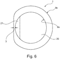
- FIG. 5 and Fig. 6 is exemplified how the reduced wall thickness is generated in the direction of the brake disc of the wheel to be coupled portion of the device 1.
- the original wall thickness in this area that is after the forming to produce the device 1, but before the stock removal, is shown by the dashed lines.
- As a nose or a pin causes, for example, by sliding back and forth in the device 1, a reduction of the wall thickness in the region of contact between the projection and inside 9a, the remaining area of the inside 9a and the outside of the wall 9b remain unchanged.
- the diameter of the cylinder-like device 20 in the region of the projection 21 is greater than the average inner diameter of the device 1.
- the cylinder-like device 20 is moved against little resistance in the device 1, wherein it is small amounts of the material of each movement the contact area of the inside of the wall of the device 9a lifts.
- the material of the device 1 is gradually thinned out in the area directed towards the brake disk of the wheel to be coupled, ie the thickness of the wall of the device 1 is reduced at this point.
- the amount of material lifted depends on the thickness of the wall of the device 1, so that a total of a stable press-in connection with the ball joint 4 is possible without the device 1 its structural integrity loses.
- the cylinder-like device 20 is moved in the device 1 until the desired amount has been lifted, as in Fig. 5 represented by the solid line.
- the wall thickness of the inner side 9a is thereby changed in the direction of the brake disc of the wheel to be coupled.
- the original wall thickness is preferably about 4 mm, but may be higher or lower.
- 0.1 to 0.9 mm are removed from the inner side 9a; 1.0 mm, also preferably 1.2 mm, also preferably 1.3 mm, also preferably 1.4 mm, also preferably 1.5, are also preferred mm, also preferably 1.6 mm, also preferably 1.7 mm, also preferably 1.8 mm, also preferably 1.9 mm, and also preferably 2.0 mm and further preferably removed up to 3.0 mm.
- the removed amounts of material change in proportion.
- the reduction of the wall thickness can be achieved by means of a single cylinder-like device 20 with a projection 21 which, for example, removes material from the inner side 9a from 4.0 mm to 2.0 mm.
- various cylindrical devices 20 may be used with different sized projections to reduce the wall thickness gradually.
- Outboard material 11 is removed, unless it is required for the stability of the device 1 and the control arm.
- the removal of the external material 11 is preferably carried out by punching.
- step S1 a sheet is provided as the starting material.
- step S2 a tool for cutting and forming the sheet is provided.
- the tool is preferably designed for punching, but for other forming methods, such as bending, extrusion, pressing, pulling, deep drawing and collar pulling.
- separation processes such as, for example, stock removal can be carried out.
- the methods mentioned and also other methods can be combined with each other. Certain steps but can also be performed outside of the tool, z. B. the stock removal. For this another tool can be provided.
- a shape corresponding to the basic shape of the transverse link to be produced is cut out of the metal sheet.
- the dimensions of the shape to be cut out also referred to as a blank, are dimensioned in such a way that all regions of the transverse link that are to be formed and not to be formed are recorded in this form.
- the blank is preferably cut from the sheet by punching, so punched out.
- step S4 the blank or the sheet metal in the tool is converted into a transverse link with all link elements with a device 1 for receiving a ball joint 4.
- the device 1 is preferably formed by collar pulling.
- the device 1 can be shaped by deep drawing, for example.
- step S5 the material of the device 1, especially in the rounded transitional region 10a of the device 1, is recessed from the horizontal plane of the surface of the control arm 8 to the inside of the wall 9a of the device perpendicular thereto.
- the transition region 10a is bent back by force from the direction of the device in the direction of the opening of the device 2, that is, out of the device 1, basically. This back-diving can also be done in the o. G. Tool be performed.
- the radius of the transition region 10a is reduced to the radius of the back-up transition region 10b.
- step S6 by moving the cylinder-like device 20 in the device 1, material is lifted from the inside of the wall of the device 9a in the area facing the brake disk of the wheel to be coupled in the form of chips. This is done until a desired extension of the inner diameter of the device 1 is reached in the area directed to the brake disc of the wheel to be coupled.
- the step S6 may also be executed before the step S5.
Description
Die vorliegende Erfindung betrifft einen Querlenker für eine Vorderradaufhängung eines Kraftfahrzeugs, wobei der Querlenker über ein Kugelgelenk in Einpressverbindung mit einem Radträger verbunden ist. Radaufhängungen verbinden die Räder mit dem Fahrgestell oder der selbstragenden Karosserie eines Kraftfahrzeugs. Einzelradaufhängungen bestehen im Gegensatz zu Starrachsen aus separaten Radaufhängungen zu den beiden Seiten eines zweispurigen Kraftfahrzeugs, so dass sich die Radstellungen auf den beiden Seiten nicht gegenseitig beeinflussen. Typischerweise sind Radaufhängungen aus sogenannten Lenkern aufgebaut, welche die Räder am Fahrgestell oder Karosserie horizontal fixieren. Dabei sind Querlenker wesentliche Bestandteile von Radaufhängungen, besonders von Vorderradaufhängungen. Ein Querlenker ist quer zur Fahrtrichtung eingebaut. Eine typische Form ist ein einschaliger Dreiecksquerlenker, bei dem zwei Anbindungsarme über Gummilager mit der Karosserie und ein Anbindungsarm über ein Gelenk, typischerweise ein Kugelgelenk, mit einem Radträger eines Rades verbunden sind (
Kugelgelenke nehmen Kräfte aus mehreren Richtungen auf und übertragen Kräfte in mehrere Richtungen. Sie bestehen im Wesentlichen aus einem Gelenkzapfen, an dessen einem Ende eine Kugel ausgebildet ist, einer die Kugel des Zapfens aufnehmenden Schale und sowie einem die Schale und Teile des Kugelzapfens aufnehmenden Gelenkgehäuse. Die Kugel des Kugelzapfens gleitet in der vorgespannten, dauergeschmierten Schale, welche durch das Gehäuse gegen Feuchtigkeit und Verschmutzung geschützt ist (
Die Verbindung des Kugelgelenkgehäuses mit einem entsprechenden Anbindungsarm kann z. B. durch eine Einpressverbindung, eine Schweißverbindung, eine Schraubverbindung, eine Nietverbindung u. ä. umgesetzt werden. Die Einpressverbindung ist dabei die kostengünstigste Variante. Die Verbindung wird dabei durch Kraftschluss bewirkt. Allerdings hat die Einpressverbindung den signifikanten Nachteil, dass sie im Vergleich mit anderen Verbindungsarten einen hohen räumlichen Bedarf hat. Der hohe räumliche Bedarf ist durch die große Materialdicke der Wandung des Einpresssitzes bedingt, und durch den dadurch bedingten großen Biegeradius des Materials. Typischerweise ist der Einpresssitz ein tiefgezogener Zylinder im Material des Lenkers. Durch den hohen räumlichen Bedarf muss das eingepresste Kugelgelenk zwangsläufig weiter innerhalb der Fahrzeugdimensionen angeordnet werden als bei anderen Methoden. Dies wiederum hat einen negativen Effekt auf das Lenkverhalten des Fahrzeugs, da der Lenkrollhalbmesser nicht optimal gestaltet werden kann. Ideal ist dabei eine möglichst nahe Anordnung der Einpressverbindung an Radträger und Bremsscheibe. In der Patentschrift
Außenseite des Querlenkers in Richtung der Bremsscheibe die Materialdicke reduziert ist, um Bewegungsfreiheit zwischen dem Querlenker und der Bremsscheibe zu gewährleisten. In der Offenlegungsschrift
Es besteht damit die Aufgabe, eine Einrichtung für die Aufnahme eines Kugelgelenks durch Einpressen bereitzustellen, die unter Nutzung des im Vergleich zu anderen Verbindungsarten kostengünstigen Vorteils dabei einen günstigeren räumlichen Bedarf als herkömmliche Einpressverbindungen aufweist.It is therefore an object to provide a device for receiving a ball joint by pressing, which has a more favorable spatial requirements than conventional press-fit using the cost compared to other types of connection advantage.
Diese Aufgabe wird durch einen Querlenker mit den Merkmalen des Hauptanspruchs gelöst. Weitere vorteilhafte Ausführungsformen der Erfindung ergeben sich aus den Nebenansprüchen, den Unteransprüchen, den Figuren und den Ausführungsbeispielen.This object is achieved by a wishbone having the features of the main claim. Further advantageous embodiments of the invention will become apparent from the dependent claims, the subclaims, the figures and the embodiments.
Ein erster Aspekt der Erfindung betrifft einen Querlenker eines Kraftfahrzeugs, umfassend eine radseitige Struktur zum Ankoppeln eines Rades mit einer eine Öffnung zur Aufnahme eines Kugelgelenks in Einpressverbindung aufweisenden Einrichtung, wobei die Wandung der Einrichtung in einem für einen kraftschlüssigen Kontakt mit dem Kugelgelenk vorgesehenen Bereich eine in Bezug auf die Materialdicke im übrigen Bereich der Wandung der Einrichtung verringerte Materialdicke in einem zur Bremsscheibe des anzukoppelnden Rades gerichteten Bereich aufweist und wobei die verringerte Materialdicke (3) durch eine trennungstechnisch hergestellte Vertiefung in Bezug auf den übrigen Bereich der inneren Oberfläche der Wandung der Einrichtung bei gleichmäßiger äußerer Oberfläche geformt ist.A first aspect of the invention relates to a control arm of a motor vehicle, comprising a wheel-side structure for coupling a wheel with a device having an opening for receiving a ball joint in Einpressverbindung having means, wherein the wall of the device in a provided for frictional contact with the ball joint area in Regarding the material thickness in the remaining area of the wall of the device decreased material thickness in a brake disc of the and wherein the reduced material thickness (3) is formed by a recess formed recess with respect to the remaining portion of the inner surface of the wall of the device with a uniform outer surface.
Das Ausgangsmaterial des Querlenkers und damit auch der Einrichtung ist vorzugsweise ein Blech, d. h. ein flaches Werkstück aus Metall. Die Struktur des Querlenkers mit allen notwendigen Formen, darunter der Einrichtung zur
Aufnahme des Kugelgelenks, wird herkömmlicherweise in einem Werkzeug, das für die Durchführung aller notwendigen Bearbeitungsprozesse ausgebildet ist, erzeugt. Das Material der Einrichtung ist in dem zur Bremsscheibe des anzukoppelnden Rades gerichteten Bereich durch ein Trennverfahren so reduziert, dass die Materialdicke der Wandung der Einrichtung in Bezug auf die ursprüngliche Materialdicke an dieser Stelle geringer ist als im übrigen Bereich der Wandung der Einrichtung. Diese Reduktion der Materialdicke ist vorteilhaft, weil sie eine Einpressverbindung mit dem Kugelgelenk ermöglicht, die im Vergleich mit herkömmlichen Einpressverbindungen näher an der Bremsscheibe angeordnet werden kann. Dadurch kann vorteilhafterweise das Fahrverhalten entsprechender Kraftfahrzeuge positiv beeinflusst werden. Gleichzeitig wird durch Erhalten der Materialdicke im übrigen Bereich der Wandung der Einrichtung verglichen mit Einrichtungen, deren Materialdicke vollständig reduziert ist, vorteilhaft eine höhere Stabilität der Einpressverbindung erreicht. Dadurch kann die Einrichtung verglichen mit herkömmlichen Einrichtungen bei geringerer Breite, d. h. geringerem Außendurchmesser der Einrichtung in dem für den kraftschlüssigen Kontakt mit dem Kugelgelenk vorgesehenen Bereich, und damit geringerem räumlichen Bedarf, mit dem Kugelgelenk in einer Einpressverbindung verbunden sein.The starting material of the transverse link and thus also the device is preferably a metal plate, ie a flat workpiece made of metal. The structure of the wishbone with all the necessary forms, including the device for
Receiving the ball joint, is conventionally generated in a tool that is designed to carry out all the necessary machining processes. The material of the device is reduced in the area directed towards the brake disc of the wheel to be coupled by a separation process so that the material thickness of the wall of the device with respect to the original material thickness at this point is less than in the remaining region of the wall of the device. This reduction in material thickness is advantageous because it allows a press-fit connection with the ball joint, which can be arranged closer to the brake disc in comparison with conventional press-fit. As a result, advantageously the driving behavior of corresponding motor vehicles can be positively influenced. At the same time, by maintaining the material thickness in the remaining area of the wall of the device compared with devices whose material thickness is completely reduced, advantageously a higher stability of the press-in connection is achieved. As a result, the device can be connected to the ball joint in a press-fit connection compared to conventional devices with smaller width, ie smaller outer diameter of the device in the intended for frictional contact with the ball joint area, and thus lower spatial requirements.
Mit anderen Worten ist das Material durch die Ausbildung einer Vertiefung im inneren Bereich so reduziert, dass vorteilhaft eine nähere räumliche Anordnung der Einrichtung und damit der Verbindung von Querlenker und Rad des entsprechenden Kraftfahrzeugs an der Bremsscheibe des Rades ermöglicht wird.In other words, the material is reduced by the formation of a depression in the inner region, that advantageously a closer spatial arrangement of the device and thus the connection of the control arm and wheel of the corresponding motor vehicle on the brake disc of the wheel is made possible.
Vorzugsweise ist bei dem Querlenker der für den kraftschlüssigen Kontakt mit dem Kugelgelenk vorgesehene Bereich die Öffnung der Einrichtung. Dabei ist das Material vorteilhafterweise in Richtung der Bremsscheibe des anzukoppelnden Rades reduziert.Preferably, in the wishbone provided for the frictional contact with the ball joint area is the opening of the device. The material is advantageously reduced in the direction of the brake disc of the wheel to be coupled.
Weiterhin ist der erfindungsgemäße Querlenker vorzugsweise einschalig. Einschalige Querlenker sind vorteilhafterweise einfach und kostengünstig herstellbar, und zeichnen sich durch ein geringes Gewicht aus.Furthermore, the wishbone invention is preferably einschalig. Single-shell wishbones are advantageously simple and inexpensive to produce, and are characterized by a low weight.
Weiterhin ist der erfindungsgemäße Querlenker zusammen mit der Einrichtung vorzugsweise als einstückiges Blechelement ausgebildet. Dazu liegt das Material des gesamten Querlenkers vor dem Umformen aus einer Blechplatine geschnitten, bevorzugt ausgestanzt, vor. In einer anderen möglichen Ausführungsform sind Querlenker und Einrichtung separat hergestellt. Die Einrichtung wird dann nach der Herstellung mit dem Querlenker verbunden, z. B. durch Nieten oder Schrauben.Furthermore, the wishbone invention is preferably formed together with the device as a one-piece sheet metal element. For this purpose, the material of the entire wishbone is cut before forming from a sheet metal blank, preferably punched before. In another possible embodiment, wishbone and device are manufactured separately. The device is then connected after manufacture with the wishbone, z. B. by rivets or screws.
Das Kugelgelenk ist mit seinem Gehäuse von den Strukturen der Einrichtung so umschlossen, dass es fest durch Form- und Kraftschluss mit dem Querlenker verbunden ist. Über das eingepresste Kugellager ist der Querlenker mit einem Radlager eines Kraftfahrzeugs verbindbar.The ball joint is enclosed with its housing of the structures of the device so that it is firmly connected by positive and non-positive connection with the wishbone. About the pressed-ball bearing of the wishbone with a wheel bearing of a motor vehicle is connected.
Ein zweiter Aspekt der Erfindung betrifft ein Kraftfahrzeug mit einem erfindungsgemäßen Querlenker. Das erfindungsgemäße Kraftfahrzeug umfasst also einen Querlenkermit einer radseitigen Struktur zum Ankoppeln eines Rades mit einer eine Öffnung zur Aufnahme eines Kugelgelenks aufweisenden Einrichtung, wobei die Wandung der Einrichtung in einem für einen kraftschlüssigen Kontakt mit dem Kugelgelenk eine trennungstechnisch hergestellte Reduktion der Materialdicke aufweist, und bei der die Reduktion der Materialdicke nur in dem zur Bremsscheibe des anzukoppelnden Rades gerichteten Bereich ausgebildet ist.A second aspect of the invention relates to a motor vehicle with a control arm according to the invention. The motor vehicle according to the invention thus comprises a transverse link with a wheel-side structure for coupling a wheel with an opening for receiving a ball joint having device, wherein the wall of the device in a frictional contact with the ball joint has a separation technology produced reduction of the material thickness, and in the the reduction of the material thickness is formed only in the area directed to the brake disc of the wheel to be coupled.
Ein dritter Aspekt der Erfindung betrifft ein Verfahren zur Herstellung eines erfindungsgemäßen Querlenkers, umfassend die Schritte:
- Bereitstellen eines Blechs als Ausgangsmaterial,
- Bereitstellen eines Werkzeug zum Schneiden und Umformen des ausgeschnittenen Blechs,
- Schneiden eines der Grundform des Querlenkers entsprechenden Form aus dem Blech,
- Umformen des ausgeschnittenen Blechs zu einem Querlenker mit allen Lenkerelementen, umfassend eine Einrichtung zur Aufnahme eines Kugelgelenks in Einpressverbindung,
- Abtrennen von Material von der Innenseite der Wand der Einrichtung in einem für einen kraftschlüssigen Kontakt mit dem Kugelgelenk vorgesehenen Bereich,
- Providing a sheet as a starting material,
- Providing a tool for cutting and forming the cut sheet,
- Cutting one of the basic shape of the wishbone corresponding form of the sheet,
- Forming the cut-out sheet into a transverse link with all the link elements, comprising means for receiving a ball joint in press-fit connection,
- Separating material from the inside of the wall of the device in a region intended for frictional contact with the ball joint,
Die Vorteile des Verfahrens entsprechen dabei denen des Querlenkers.The advantages of the method correspond to those of the wishbone.
Die Einrichtung wird bevorzugt durch ein Durchziehen eines Ziehstempels im Material des Querlenkers geformt. Dadurch entsteht ein sogenannter Blechdurchzug. Dieses Verfahren wird auch Kragenziehen genannt. Eine weitere Möglichkeit zur Formung der Einrichtung ist das Tiefziehen.The device is preferably formed by pulling a drawing punch in the material of the control arm. This creates a so-called sheet metal passage. This procedure is also called collar pulling. Another way to shape the device is thermoforming.
Bevorzugt wird in dem Verfahren die Abtrennung von Material durch Abspanen durchgeführt. Dabei werden kleine Materialteile (Späne) von der Oberfläche der Innenseite abgehoben. Das Abspanen ist vergleichsweise als eine Art Hobeln vorstellbar.Preferably, the separation of material is carried out by cutting in the process. Small pieces of material (chips) are lifted off the surface of the inside. The stock removal is comparatively conceivable as a kind of planing.
Besonders bevorzugt wird das Abtrennen des Materials mittels einer zylinderartigen Vorrichtung durchgeführt, wobei der spanabhebende Bereich der Vorrichtung als ein Vorsprung aus der im übrigen Bereich kreiszylinderartig geformten Vorrichtung ausgebildet ist. Durch die kreiszylinderartige Formung der Vorrichtung kann diese in dem Durchzug geführt werden. Der Vorsprung, auch als Nase oder Zapfen bezeichnet, hat vorzugsweise eine gerundete Form. Durch die gerundete Form kann durch Abspanen eine gleichmäßig ausgebildete Vertiefung in der inneren Oberfläche der Wandung der Einrichtung erzeugt werden.Particularly preferably, the separation of the material is carried out by means of a cylinder-like device, wherein the cutting region of the device is formed as a projection of the device in the remaining area circular cylindrical shaped. By the circular cylindrical shaping of the device, this can be performed in the passage become. The projection, also referred to as nose or pin, preferably has a rounded shape. The rounded shape can be created by cutting a uniformly formed depression in the inner surface of the wall of the device.
Vorzugsweise ist der Durchmesser der zylinderartigen Vorrichtung im Bereich des Vorsprungs größer als der Innenradius des Durchzugs. Der Größenunterschied ist dabei nur geringfügig, so dass die zylinderartige Vorrichtung noch in der Einrichtung gegen geringen Widerstand gleiten kann, wobei es entsprechend kleine Mengen des Materials von der Innenseite der Wand der Einrichtung abhebt. Dabei können entsprechend des sich vergrößernden Innendurchmessers des Durchzugs zylinderartige Vorrichtungen mit verschiedenen, tendenziell größeren Durchmessern verwendet werden.Preferably, the diameter of the cylinder-like device in the region of the projection is greater than the inner radius of the passage. The difference in size is only slight, so that the cylinder-like device can still slide in the device against low resistance, and it lifts accordingly small amounts of the material from the inside of the wall of the device. In this case, according to the increasing inner diameter of the passage cylinder-like devices with different, tend to be larger diameters can be used.
Vorzugsweise umfasst das Verfahren den zusätzlichen Schritt:
- Zurückstauchen des Übergangsbereiches des Einpresssitzes von der horizontalen Ebene der Oberfläche des Querlenkers zur senkrecht dazu angeordneten Innenseite der Wand der Einrichtung.
- Diving back the transition region of the press fit from the horizontal plane of the surface of the control arm to the arranged perpendicular to the inside of the wall of the device.
Dabei wird der gerundete Übergangsbereich durch Kraftwirkung entgegen der Richtung z. B. des Durchzugs zurückgebogen. Dadurch wird der Radius des gerundeten Übergangsbereichs der Einrichtung vorteilhaft verringert, denn durch den geringeren Biegeradius verschiebt sich die maximale Höhe der vorgesehenen Einpressverbindung, d. h. Nähe zur Öffnung der Einrichtung bzw. zur Ebene der Oberfläche des Querlenkers. Auf diese Weise muss das Kugelgelenk weniger weit innerhalb des Einpresssitzes angebracht werden und wird der Lenkrollhalbmesser des mit dem Querlenker verbundenen Kraftfahrzeugrades günstig beeinflusst. Das Stauchen des Materials ist auch vorteilhaft, weil dadurch auch eine Materialverdichtung des Einpresssitzes bewirkt wird.In this case, the rounded transition region by force against the direction z. B. the passage bent back. As a result, the radius of the rounded transition region of the device is advantageously reduced, because the lower bending radius shifts the maximum height of the intended press-fit connection, ie. H. Close to the opening of the device or to the plane of the surface of the control arm. In this way, the ball joint must be mounted less far within the press fit and the Lenkrollenhalbmesser the connected to the wishbone motor vehicle wheel is favorably influenced. The upsetting of the material is also advantageous because it also causes a material compression of the press fit.
Weiterhin umfasst das Verfahren vorzugsweise den zusätzlichen Schritt:
- Entfernen der in radialer Richtung außen von der Öffnung liegenden Bereiche der Einrichtung.
- Removing the lying in the radial direction outside of the opening areas of the device.
Durch die Abtrennung nichtbenötigten Materials werden vorteilhafterweise der Außendurchmesser der Einrichtung und damit deren räumlicher Bedarf weiter reduziert.By separating unneeded material advantageously the outer diameter of the device and thus their spatial needs are further reduced.
Die Erfindung wird anhand der Figuren näher beschrieben. Es zeigen:
-
Figur 1 - eine Querschnittsansicht einer beispielhaften Ausführungsform eines erfindungsgemäßen Querlenkers mit einem eingepressten Kugelgelenk in einer Einrichtung zur Aufnahme des Kugelgelenks.
-
Figur 2 - eine Querschnittsansicht der Ausführungsform gemäß
Fig. 1 . -
Figur 3 - eine Querschnittsansicht der Ausführungsform gemäß
Fig. 1 . -
Figur 4 - eine angeschnittene Ansicht der Ausführungsform gemäß
Fig. 1 . -
Figur 5 - eine Darstellung einer beispielhaften Ausführungsform eines erfindungsgemäßen Verfahrens in Querschnittsansicht.
-
Figur 6 - die Ausführungsform gemäß
Fig. 5 in Querschnittsansicht von oben gesehen. -
Figur 7 - ein Fließdiagramm der Ausführungsform gemäß
Fig. 5 .
- FIG. 1
- a cross-sectional view of an exemplary embodiment of a control arm according to the invention with a pressed-ball joint in a device for receiving the ball joint.
- FIG. 2
- a cross-sectional view of the embodiment according to
Fig. 1 , - FIG. 3
- a cross-sectional view of the embodiment according to
Fig. 1 , - FIG. 4
- a cutaway view of the embodiment according to
Fig. 1 , - FIG. 5
- a representation of an exemplary embodiment of a method according to the invention in cross-sectional view.
- FIG. 6
- the embodiment according to
Fig. 5 seen in cross-sectional view from above. - FIG. 7
- a flow chart of the embodiment according to
Fig. 5 ,
In der Darstellung von
Die Einrichtung 1 ist z. B. als Blechdurchzug durch die Umformmethode Kragenziehen herstellbar, wodurch eine Form wie in
Dabei entsteht am Übergang zwischen der horizontalen Ebene der Oberfläche des Querlenkers 8 und der zur Oberfläche des Querlenkers 8 senkrechten Innenseite der Wand 9a der Einrichtung 1 eine Rundung bzw. gerundeter Übergangsbereich 10a, dessen unterer Abschluss, markiert durch die Linie 12, die maximale Höhe der vorgesehenen Einpressverbindung definiert.This results in the transition between the horizontal plane of the surface of the
In
In
In
Außenstehendes Material 11 wird entfernt, soweit es nicht zur Stabilität der Einrichtung 1 und des Querlenkers benötigt wird. Die Entfernung des außenstehenden Materials 11 wird bevorzugt durch Stanzen ausgeführt.
In einer beispielhaften Ausführungsform des Verfahrens wird gemäß der Darstellung in
In einem weiteren Schritt S3 wird eine der Grundform des herzustellenden Querlenkers entsprechende Form aus dem Blech ausgeschnitten. Dabei werden die Dimensionen der auszuschneidenden Form, auch als Rohling bezeichnet, so bemessen, dass alle umzuformenden und nicht umzuformenden Bereiche des Querlenkers in dieser Form erfasst sind. Der Rohling wird aus dem Blech bevorzugt durch Stanzen ausgeschnitten, also ausgestanzt.In a further step S3, a shape corresponding to the basic shape of the transverse link to be produced is cut out of the metal sheet. The dimensions of the shape to be cut out, also referred to as a blank, are dimensioned in such a way that all regions of the transverse link that are to be formed and not to be formed are recorded in this form. The blank is preferably cut from the sheet by punching, so punched out.
In Schritt S4 wird der Rohling bzw. das Blech in dem Werkzeug zu einem Querlenker mit allen Lenkerelementen mit einer Einrichtung 1 zur Aufnahme eines Kugelgelenks 4 umgeformt. Dabei wird die Einrichtung 1 bevorzugt durch Kragenziehen geformt. Alternativ ist die Einrichtung 1 beispielsweise durch Tiefziehen formbar.In step S4, the blank or the sheet metal in the tool is converted into a transverse link with all link elements with a
In Schritt S5 wird das Material der Einrichtung 1, besonders im gerundeten Übergangsbereich 10a der Einrichtung 1 von der horizontalen Ebene der Oberfläche des Querlenkers 8 zur senkrecht dazu angeordneten Innenseite der Wand der Einrichtung 9a, zurückgestaucht. Dazu wird der Übergangsbereich 10a durch Kraftwirkung aus der Richtung der Einrichtung in die Richtung der Öffnung der Einrichtung 2, also aus der Einrichtung 1 heraus, im Grunde zurückgebogen. Dieses Zurückstauchen kann ebenfalls in dem o. g. Werkzeug durchgeführt werden. Der Radius des Übergangsbereiches 10a wird dabei zum Radius des zurückgestauchten Übergangsbereichs 10b verringert.In step S5, the material of the
In Schritt S6 wird durch Bewegung der zylinderartigen Vorrichtung 20 in der Einrichtung 1 Material von der Innenseite der Wand der Einrichtung 9a in dem zur Bremsscheibe des anzukoppelnden Rades gerichteten Bereich in Form von Spänen abgehoben. Dies wird solange durchgeführt, bis eine gewünschte Erweiterung des Innendurchmessers der Einrichtung 1 in dem zur Bremsscheibe des anzukoppelnden Rades gerichteten Bereich erreicht ist. Der Schritt S6 kann auch vor dem Schritt S5 ausgeführt werden.In step S6, by moving the cylinder-
- 11
- = Einrichtung= Institution
- 22
- = Öffnung der Einrichtung= Opening of the device
- 33
- = Reduktion= Reduction
- 44
- = Kugelgelenk= Ball joint
- 5a5a
- = Zapfen des Kugelgelenks= Pin of the ball joint
- 5b5b
- = Kugel des Kugelgelenks= Ball of the ball joint
- 66
- = Schale des Kugelgelenks= Shell of the ball joint
- 77
- = Gehäuse des Kugelgelenks= Housing of the ball joint
- 88th
- = horizontale Ebene des Querlenkers= horizontal plane of the control arm
- 9a9a
- = Innenseite der Wand des Einrichtung= Inside of the wall of the device
- 9b9b
- = Außenseite der Wand des Einrichtung= Outside of the wall of the device
- 10a10a
- = gerundeter Übergangsbereich der Einrichtung= rounded transition area of the device
- 10b10b
- = zurückgestauchter Übergangsbereich des Einrichtung= recessed transition area of the device
- 1111
- = außenstehendes Material der Einrichtung= outside material of the device
- 1212
- = maximale Höhe der Einpressverbindung= maximum height of the press-in connection
- 1313
- = Außendimension der Einpressverbindung= External dimension of the pressfit connection
- 1414
- = Indikation der Entfernung vom Zentrum des Kugelgelenks zum Außendurchmesser der EinrichtungIndication of the distance from the center of the ball joint to the outer diameter of the device
- 2020
- = zylinderartige Vorrichtung= cylinder-like device
- 2121
- = Vorsprung der Vorrichtung= Projection of the device
Claims (12)
- Transverse link of a motor vehicle, comprising a wheel-side structure for the coupling-on of a wheel, having a device (1) which has an opening (2) for receiving a ball joint (4) in a press-fit connection, wherein the wall of the device (1) in a region provided for force-fitting contact with the ball joint (4) has a reduced material thickness (3), in relation to the material thickness in the remaining region of the wall of the device, in a region directed towards the brake disc of the wheel to be coupled on, characterized in that the reduced material thickness (3) is formed by means of a depression, produced by cutting techniques, in relation to the remaining region of the inner surface of the wall of the device in the case of a uniform outer surface.
- Transverse link according to Claim 1, in which the region provided for the force-fitting contact with the ball joint (4) is the opening (2) of the device (1) .
- Transverse link according to any of the preceding claims, wherein the transverse link is of single-shell form.
- Transverse link according to any of the preceding claims, in which the device (1) is formed integrally with the transverse link.
- Motor vehicle having a transverse link according to any of Claims 1 - 4.
- Method for producing a transverse link according to any of Claims 1 - 4, comprising the steps:- providing a metal sheet as starting material,- providing a tool for cutting and deforming the cut-out metal sheet,- cutting a shape corresponding to the basic shape of the transverse link out of the metal sheet,- deforming the cut-out metal sheet to form a transverse link with all link elements, comprising a device for receiving a ball joint in a press-fit connection,- cutting off material from the inner side of the wall of the device in a region intended for force-fitting contact with the ball joint,characterized in that
the material is cut off only in a region directed towards the brake disc of the wheel to be coupled on. - Method according to Claim 6, wherein the device is formed by a rim hole of a drawing punch.
- Method according to either of Claims 6 and 7, wherein the cutting-off of material is performed by means of a chip-removing process.
- Method according to any of Claims 6 - 8, wherein the cutting-off of the material is performed by means of a cylindrical device, wherein the chip-removing region of the device is formed as a projection from the device which is of circular cylindrical shape in the remaining region.
- Method according to Claim 9, wherein the diameter of the cylindrical device is greater in the region of the projection than the internal radius of the rim hole.
- Method according to any of Claims 6 - 10, additionally comprising the step:- backward-upsetting the transition region of the press fit from the horizontal plane of the surface of the transverse link to the inner side, arranged perpendicular thereto, of the wall of the device.
- Method according to any of Claims 6 - 11, additionally comprising the step:- removing those regions of the device which are situated outside the opening in a radial direction.
Applications Claiming Priority (1)
| Application Number | Priority Date | Filing Date | Title |
|---|---|---|---|
| DE102014222575.2A DE102014222575A1 (en) | 2014-11-05 | 2014-11-05 | Wishbone with ball joint in press-fit connection |
Publications (2)
| Publication Number | Publication Date |
|---|---|
| EP3017974A1 EP3017974A1 (en) | 2016-05-11 |
| EP3017974B1 true EP3017974B1 (en) | 2019-01-16 |
Family
ID=53015697
Family Applications (1)
| Application Number | Title | Priority Date | Filing Date |
|---|---|---|---|
| EP15165899.4A Active EP3017974B1 (en) | 2014-11-05 | 2015-04-30 | Transverse control arm with ball joint in press-fit connection |
Country Status (3)
| Country | Link |
|---|---|
| EP (1) | EP3017974B1 (en) |
| CN (1) | CN105564171A (en) |
| DE (1) | DE102014222575A1 (en) |
Families Citing this family (1)
| Publication number | Priority date | Publication date | Assignee | Title |
|---|---|---|---|---|
| DE102016208579B3 (en) * | 2016-05-19 | 2017-08-31 | Zf Friedrichshafen Ag | Method for producing a vehicle component |
Family Cites Families (10)
| Publication number | Priority date | Publication date | Assignee | Title |
|---|---|---|---|---|
| DE19937888B4 (en) * | 1999-08-16 | 2004-02-05 | Sachsenring Fahrzeugtechnik Gmbh | ball joint |
| DE10212791B4 (en) * | 2002-03-22 | 2009-09-10 | Benteler Automobiltechnik Gmbh | wishbone |
| CA2416703C (en) | 2003-01-20 | 2011-11-22 | Multimatic Inc. | Structural i-beam automotive suspension arm |
| US7648304B2 (en) * | 2004-11-12 | 2010-01-19 | Honda Motor Co., Ltd | Shield for a vehicle suspension ball joint |
| DE102005025551C5 (en) * | 2005-06-01 | 2016-06-23 | Zf Friedrichshafen Ag | Joint and / or bearing arrangement |
| DE102005034210B4 (en) | 2005-07-19 | 2008-04-10 | Zf Friedrichshafen Ag | Method for producing a ball joint and joint produced thereafter |
| DE102006002395B4 (en) | 2006-01-17 | 2008-10-16 | Zf Friedrichshafen Ag | Ball joint, and method for producing a joint housing |
| US8777245B2 (en) * | 2012-11-16 | 2014-07-15 | The Pullman Company | Optimized wall thickness torque rod |
| DE102013200406A1 (en) * | 2013-01-14 | 2014-07-17 | Ford Global Technologies, Llc | Method for producing a transverse link |
| US8757648B1 (en) * | 2013-05-03 | 2014-06-24 | Mevotech Lp | Control arm assembly with ball joint for automotive suspension |
-
2014
- 2014-11-05 DE DE102014222575.2A patent/DE102014222575A1/en not_active Ceased
-
2015
- 2015-04-30 EP EP15165899.4A patent/EP3017974B1/en active Active
- 2015-10-27 CN CN201510707581.7A patent/CN105564171A/en active Pending
Non-Patent Citations (1)
| Title |
|---|
| None * |
Also Published As
| Publication number | Publication date |
|---|---|
| EP3017974A1 (en) | 2016-05-11 |
| CN105564171A (en) | 2016-05-11 |
| DE102014222575A1 (en) | 2016-05-12 |
Similar Documents
| Publication | Publication Date | Title |
|---|---|---|
| EP2982529B1 (en) | Pneumatic support for a pneumatically supported axle of a commercial vehicle | |
| EP3112193A1 (en) | Method for obtaining a suspension arm for automotive vehicles and suspension arm | |
| EP2910454B1 (en) | Undercarriage component with eccentric disc stop | |
| EP2961623B1 (en) | Chassis for a commercial vehicle, axle body and method for producing an axle body | |
| DE102018128077A1 (en) | Motor vehicle driver and method for producing a motor vehicle driver | |
| DE102014208003A1 (en) | Planet carrier for a planetary gear made of welded parts | |
| EP3310594B1 (en) | Link for a wheel suspension | |
| EP2000335B1 (en) | Axle component and method of producing an axle component | |
| WO2013007626A2 (en) | Axle and production method | |
| EP3157769B1 (en) | Method for producing a chassis component | |
| EP3017974B1 (en) | Transverse control arm with ball joint in press-fit connection | |
| DE102004009722A1 (en) | Transverse control arm for use in vehicle suspensions has two or more sections with bearings at their ends, arm being made from sheet metal and sections having flanges along their edges which give it asymmetric cross-section | |
| DE102016201457B4 (en) | Method for manufacturing a suspension arm | |
| DE102008015799A1 (en) | Wheel guiding strut for motor vehicle, has wheel sided connecting point, assembly side connecting point and connecting structure extending between two points | |
| DE102014222579B4 (en) | Wishbone with ball joint in press-in connection | |
| EP2772372A1 (en) | Suspension for a commercial vehicle, axle body and method for manufacturing an axle body | |
| DE102017206861B4 (en) | Method for producing a suspension strut fork and suspension strut fork for a motor vehicle | |
| EP2810799A1 (en) | Method for producing a suspension arm and suspension arm for a vehicle | |
| DE102014222576B4 (en) | Wishbone with ball joint in press-in connection | |
| DE102014222577A1 (en) | Wishbone with ball joint in press-fit connection | |
| EP2428375B1 (en) | Method for manufacturing a stabiliser and stabiliser | |
| DE102017212482A1 (en) | Spring-loaded fork for a vehicle wheel suspension | |
| EP3702180B1 (en) | Chassis for a commercial vehicle, shell for same and arrangement of two shells forming a pair | |
| EP3017975B1 (en) | Transverse control arm with ball joint in press-fit connection | |
| DE102014222574B4 (en) | Wishbone with ball joint in press-in connection |
Legal Events
| Date | Code | Title | Description |
|---|---|---|---|
| PUAI | Public reference made under article 153(3) epc to a published international application that has entered the european phase |
Free format text: ORIGINAL CODE: 0009012 |
|
| AK | Designated contracting states |
Kind code of ref document: A1 Designated state(s): AL AT BE BG CH CY CZ DE DK EE ES FI FR GB GR HR HU IE IS IT LI LT LU LV MC MK MT NL NO PL PT RO RS SE SI SK SM TR |
|
| AX | Request for extension of the european patent |
Extension state: BA ME |
|
| STAA | Information on the status of an ep patent application or granted ep patent |
Free format text: STATUS: REQUEST FOR EXAMINATION WAS MADE |
|
| 17P | Request for examination filed |
Effective date: 20161111 |
|
| RBV | Designated contracting states (corrected) |
Designated state(s): AL AT BE BG CH CY CZ DE DK EE ES FI FR GB GR HR HU IE IS IT LI LT LU LV MC MK MT NL NO PL PT RO RS SE SI SK SM TR |
|
| STAA | Information on the status of an ep patent application or granted ep patent |
Free format text: STATUS: EXAMINATION IS IN PROGRESS |
|
| 17Q | First examination report despatched |
Effective date: 20171016 |
|
| GRAP | Despatch of communication of intention to grant a patent |
Free format text: ORIGINAL CODE: EPIDOSNIGR1 |
|
| STAA | Information on the status of an ep patent application or granted ep patent |
Free format text: STATUS: GRANT OF PATENT IS INTENDED |
|
| RIC1 | Information provided on ipc code assigned before grant |
Ipc: F16C 11/06 20060101ALI20181003BHEP Ipc: B60G 7/00 20060101AFI20181003BHEP |
|
| INTG | Intention to grant announced |
Effective date: 20181029 |
|
| GRAS | Grant fee paid |
Free format text: ORIGINAL CODE: EPIDOSNIGR3 |
|
| GRAA | (expected) grant |
Free format text: ORIGINAL CODE: 0009210 |
|
| STAA | Information on the status of an ep patent application or granted ep patent |
Free format text: STATUS: THE PATENT HAS BEEN GRANTED |
|
| AK | Designated contracting states |
Kind code of ref document: B1 Designated state(s): AL AT BE BG CH CY CZ DE DK EE ES FI FR GB GR HR HU IE IS IT LI LT LU LV MC MK MT NL NO PL PT RO RS SE SI SK SM TR |
|
| REG | Reference to a national code |
Ref country code: GB Ref legal event code: FG4D Free format text: NOT ENGLISH |
|
| REG | Reference to a national code |
Ref country code: CH Ref legal event code: EP |
|
| REG | Reference to a national code |
Ref country code: IE Ref legal event code: FG4D Free format text: LANGUAGE OF EP DOCUMENT: GERMAN |
|
| REG | Reference to a national code |
Ref country code: DE Ref legal event code: R096 Ref document number: 502015007683 Country of ref document: DE |
|
| REG | Reference to a national code |
Ref country code: AT Ref legal event code: REF Ref document number: 1089450 Country of ref document: AT Kind code of ref document: T Effective date: 20190215 |
|
| PGFP | Annual fee paid to national office [announced via postgrant information from national office to epo] |
Ref country code: FR Payment date: 20190123 Year of fee payment: 11 |
|
| REG | Reference to a national code |
Ref country code: NL Ref legal event code: MP Effective date: 20190116 |
|
| REG | Reference to a national code |
Ref country code: LT Ref legal event code: MG4D |
|
| PG25 | Lapsed in a contracting state [announced via postgrant information from national office to epo] |
Ref country code: NL Free format text: LAPSE BECAUSE OF FAILURE TO SUBMIT A TRANSLATION OF THE DESCRIPTION OR TO PAY THE FEE WITHIN THE PRESCRIBED TIME-LIMIT Effective date: 20190116 |
|
| PG25 | Lapsed in a contracting state [announced via postgrant information from national office to epo] |
Ref country code: ES Free format text: LAPSE BECAUSE OF FAILURE TO SUBMIT A TRANSLATION OF THE DESCRIPTION OR TO PAY THE FEE WITHIN THE PRESCRIBED TIME-LIMIT Effective date: 20190116 Ref country code: SE Free format text: LAPSE BECAUSE OF FAILURE TO SUBMIT A TRANSLATION OF THE DESCRIPTION OR TO PAY THE FEE WITHIN THE PRESCRIBED TIME-LIMIT Effective date: 20190116 Ref country code: PT Free format text: LAPSE BECAUSE OF FAILURE TO SUBMIT A TRANSLATION OF THE DESCRIPTION OR TO PAY THE FEE WITHIN THE PRESCRIBED TIME-LIMIT Effective date: 20190516 Ref country code: NO Free format text: LAPSE BECAUSE OF FAILURE TO SUBMIT A TRANSLATION OF THE DESCRIPTION OR TO PAY THE FEE WITHIN THE PRESCRIBED TIME-LIMIT Effective date: 20190416 Ref country code: FI Free format text: LAPSE BECAUSE OF FAILURE TO SUBMIT A TRANSLATION OF THE DESCRIPTION OR TO PAY THE FEE WITHIN THE PRESCRIBED TIME-LIMIT Effective date: 20190116 Ref country code: LT Free format text: LAPSE BECAUSE OF FAILURE TO SUBMIT A TRANSLATION OF THE DESCRIPTION OR TO PAY THE FEE WITHIN THE PRESCRIBED TIME-LIMIT Effective date: 20190116 Ref country code: PL Free format text: LAPSE BECAUSE OF FAILURE TO SUBMIT A TRANSLATION OF THE DESCRIPTION OR TO PAY THE FEE WITHIN THE PRESCRIBED TIME-LIMIT Effective date: 20190116 |
|
| PG25 | Lapsed in a contracting state [announced via postgrant information from national office to epo] |
Ref country code: BG Free format text: LAPSE BECAUSE OF FAILURE TO SUBMIT A TRANSLATION OF THE DESCRIPTION OR TO PAY THE FEE WITHIN THE PRESCRIBED TIME-LIMIT Effective date: 20190416 Ref country code: GR Free format text: LAPSE BECAUSE OF FAILURE TO SUBMIT A TRANSLATION OF THE DESCRIPTION OR TO PAY THE FEE WITHIN THE PRESCRIBED TIME-LIMIT Effective date: 20190417 Ref country code: RS Free format text: LAPSE BECAUSE OF FAILURE TO SUBMIT A TRANSLATION OF THE DESCRIPTION OR TO PAY THE FEE WITHIN THE PRESCRIBED TIME-LIMIT Effective date: 20190116 Ref country code: HR Free format text: LAPSE BECAUSE OF FAILURE TO SUBMIT A TRANSLATION OF THE DESCRIPTION OR TO PAY THE FEE WITHIN THE PRESCRIBED TIME-LIMIT Effective date: 20190116 Ref country code: IS Free format text: LAPSE BECAUSE OF FAILURE TO SUBMIT A TRANSLATION OF THE DESCRIPTION OR TO PAY THE FEE WITHIN THE PRESCRIBED TIME-LIMIT Effective date: 20190516 Ref country code: LV Free format text: LAPSE BECAUSE OF FAILURE TO SUBMIT A TRANSLATION OF THE DESCRIPTION OR TO PAY THE FEE WITHIN THE PRESCRIBED TIME-LIMIT Effective date: 20190116 |
|
| REG | Reference to a national code |
Ref country code: DE Ref legal event code: R097 Ref document number: 502015007683 Country of ref document: DE |
|
| PG25 | Lapsed in a contracting state [announced via postgrant information from national office to epo] |
Ref country code: IT Free format text: LAPSE BECAUSE OF FAILURE TO SUBMIT A TRANSLATION OF THE DESCRIPTION OR TO PAY THE FEE WITHIN THE PRESCRIBED TIME-LIMIT Effective date: 20190116 Ref country code: RO Free format text: LAPSE BECAUSE OF FAILURE TO SUBMIT A TRANSLATION OF THE DESCRIPTION OR TO PAY THE FEE WITHIN THE PRESCRIBED TIME-LIMIT Effective date: 20190116 Ref country code: CZ Free format text: LAPSE BECAUSE OF FAILURE TO SUBMIT A TRANSLATION OF THE DESCRIPTION OR TO PAY THE FEE WITHIN THE PRESCRIBED TIME-LIMIT Effective date: 20190116 Ref country code: SK Free format text: LAPSE BECAUSE OF FAILURE TO SUBMIT A TRANSLATION OF THE DESCRIPTION OR TO PAY THE FEE WITHIN THE PRESCRIBED TIME-LIMIT Effective date: 20190116 Ref country code: EE Free format text: LAPSE BECAUSE OF FAILURE TO SUBMIT A TRANSLATION OF THE DESCRIPTION OR TO PAY THE FEE WITHIN THE PRESCRIBED TIME-LIMIT Effective date: 20190116 Ref country code: DK Free format text: LAPSE BECAUSE OF FAILURE TO SUBMIT A TRANSLATION OF THE DESCRIPTION OR TO PAY THE FEE WITHIN THE PRESCRIBED TIME-LIMIT Effective date: 20190116 Ref country code: AL Free format text: LAPSE BECAUSE OF FAILURE TO SUBMIT A TRANSLATION OF THE DESCRIPTION OR TO PAY THE FEE WITHIN THE PRESCRIBED TIME-LIMIT Effective date: 20190116 |
|
| PLBE | No opposition filed within time limit |
Free format text: ORIGINAL CODE: 0009261 |
|
| STAA | Information on the status of an ep patent application or granted ep patent |
Free format text: STATUS: NO OPPOSITION FILED WITHIN TIME LIMIT |
|
| PG25 | Lapsed in a contracting state [announced via postgrant information from national office to epo] |
Ref country code: SM Free format text: LAPSE BECAUSE OF FAILURE TO SUBMIT A TRANSLATION OF THE DESCRIPTION OR TO PAY THE FEE WITHIN THE PRESCRIBED TIME-LIMIT Effective date: 20190116 |
|
| REG | Reference to a national code |
Ref country code: CH Ref legal event code: PL |
|
| REG | Reference to a national code |
Ref country code: BE Ref legal event code: MM Effective date: 20190430 |
|
| 26N | No opposition filed |
Effective date: 20191017 |
|
| PG25 | Lapsed in a contracting state [announced via postgrant information from national office to epo] |
Ref country code: MC Free format text: LAPSE BECAUSE OF FAILURE TO SUBMIT A TRANSLATION OF THE DESCRIPTION OR TO PAY THE FEE WITHIN THE PRESCRIBED TIME-LIMIT Effective date: 20190116 Ref country code: LU Free format text: LAPSE BECAUSE OF NON-PAYMENT OF DUE FEES Effective date: 20190430 |
|
| PG25 | Lapsed in a contracting state [announced via postgrant information from national office to epo] |
Ref country code: LI Free format text: LAPSE BECAUSE OF NON-PAYMENT OF DUE FEES Effective date: 20190430 Ref country code: CH Free format text: LAPSE BECAUSE OF NON-PAYMENT OF DUE FEES Effective date: 20190430 |
|
| PG25 | Lapsed in a contracting state [announced via postgrant information from national office to epo] |
Ref country code: SI Free format text: LAPSE BECAUSE OF FAILURE TO SUBMIT A TRANSLATION OF THE DESCRIPTION OR TO PAY THE FEE WITHIN THE PRESCRIBED TIME-LIMIT Effective date: 20190116 Ref country code: BE Free format text: LAPSE BECAUSE OF NON-PAYMENT OF DUE FEES Effective date: 20190430 |
|
| PG25 | Lapsed in a contracting state [announced via postgrant information from national office to epo] |
Ref country code: TR Free format text: LAPSE BECAUSE OF FAILURE TO SUBMIT A TRANSLATION OF THE DESCRIPTION OR TO PAY THE FEE WITHIN THE PRESCRIBED TIME-LIMIT Effective date: 20190116 |
|
| PG25 | Lapsed in a contracting state [announced via postgrant information from national office to epo] |
Ref country code: IE Free format text: LAPSE BECAUSE OF NON-PAYMENT OF DUE FEES Effective date: 20190430 |
|
| PGFP | Annual fee paid to national office [announced via postgrant information from national office to epo] |
Ref country code: GB Payment date: 20200327 Year of fee payment: 6 |
|
| PG25 | Lapsed in a contracting state [announced via postgrant information from national office to epo] |
Ref country code: FR Free format text: LAPSE BECAUSE OF NON-PAYMENT OF DUE FEES Effective date: 20200430 |
|
| PG25 | Lapsed in a contracting state [announced via postgrant information from national office to epo] |
Ref country code: CY Free format text: LAPSE BECAUSE OF FAILURE TO SUBMIT A TRANSLATION OF THE DESCRIPTION OR TO PAY THE FEE WITHIN THE PRESCRIBED TIME-LIMIT Effective date: 20190116 |
|
| REG | Reference to a national code |
Ref country code: AT Ref legal event code: MM01 Ref document number: 1089450 Country of ref document: AT Kind code of ref document: T Effective date: 20200430 |
|
| PG25 | Lapsed in a contracting state [announced via postgrant information from national office to epo] |
Ref country code: MT Free format text: LAPSE BECAUSE OF FAILURE TO SUBMIT A TRANSLATION OF THE DESCRIPTION OR TO PAY THE FEE WITHIN THE PRESCRIBED TIME-LIMIT Effective date: 20190116 Ref country code: HU Free format text: LAPSE BECAUSE OF FAILURE TO SUBMIT A TRANSLATION OF THE DESCRIPTION OR TO PAY THE FEE WITHIN THE PRESCRIBED TIME-LIMIT; INVALID AB INITIO Effective date: 20150430 |
|
| PG25 | Lapsed in a contracting state [announced via postgrant information from national office to epo] |
Ref country code: AT Free format text: LAPSE BECAUSE OF NON-PAYMENT OF DUE FEES Effective date: 20200430 |
|
| GBPC | Gb: european patent ceased through non-payment of renewal fee |
Effective date: 20210430 |
|
| PG25 | Lapsed in a contracting state [announced via postgrant information from national office to epo] |
Ref country code: GB Free format text: LAPSE BECAUSE OF NON-PAYMENT OF DUE FEES Effective date: 20210430 |
|
| PG25 | Lapsed in a contracting state [announced via postgrant information from national office to epo] |
Ref country code: MK Free format text: LAPSE BECAUSE OF FAILURE TO SUBMIT A TRANSLATION OF THE DESCRIPTION OR TO PAY THE FEE WITHIN THE PRESCRIBED TIME-LIMIT Effective date: 20190116 |
|
| P01 | Opt-out of the competence of the unified patent court (upc) registered |
Effective date: 20230620 |
|
| PGFP | Annual fee paid to national office [announced via postgrant information from national office to epo] |
Ref country code: DE Payment date: 20230320 Year of fee payment: 9 |