EP3017871B1 - Apparatus for classifying particulate material - Google Patents
Apparatus for classifying particulate material Download PDFInfo
- Publication number
- EP3017871B1 EP3017871B1 EP15193846.1A EP15193846A EP3017871B1 EP 3017871 B1 EP3017871 B1 EP 3017871B1 EP 15193846 A EP15193846 A EP 15193846A EP 3017871 B1 EP3017871 B1 EP 3017871B1
- Authority
- EP
- European Patent Office
- Prior art keywords
- tank
- water
- outlet
- transfer passage
- region
- Prior art date
- Legal status (The legal status is an assumption and is not a legal conclusion. Google has not performed a legal analysis and makes no representation as to the accuracy of the status listed.)
- Active
Links
- 239000011236 particulate material Substances 0.000 title claims description 12
- XLYOFNOQVPJJNP-UHFFFAOYSA-N water Substances O XLYOFNOQVPJJNP-UHFFFAOYSA-N 0.000 claims description 56
- 239000002002 slurry Substances 0.000 claims description 23
- 239000002245 particle Substances 0.000 claims description 14
- 239000000463 material Substances 0.000 claims description 9
- 230000002093 peripheral effect Effects 0.000 claims description 6
- 238000000926 separation method Methods 0.000 claims description 6
- 230000002250 progressing effect Effects 0.000 claims description 4
- 239000004576 sand Substances 0.000 description 4
- 239000007787 solid Substances 0.000 description 4
- 239000012530 fluid Substances 0.000 description 3
- 230000005484 gravity Effects 0.000 description 3
- 230000000694 effects Effects 0.000 description 1
- 239000011521 glass Substances 0.000 description 1
- 230000000630 rising effect Effects 0.000 description 1
Images


Classifications
-
- B—PERFORMING OPERATIONS; TRANSPORTING
- B03—SEPARATION OF SOLID MATERIALS USING LIQUIDS OR USING PNEUMATIC TABLES OR JIGS; MAGNETIC OR ELECTROSTATIC SEPARATION OF SOLID MATERIALS FROM SOLID MATERIALS OR FLUIDS; SEPARATION BY HIGH-VOLTAGE ELECTRIC FIELDS
- B03B—SEPARATING SOLID MATERIALS USING LIQUIDS OR USING PNEUMATIC TABLES OR JIGS
- B03B5/00—Washing granular, powdered or lumpy materials; Wet separating
- B03B5/62—Washing granular, powdered or lumpy materials; Wet separating by hydraulic classifiers, e.g. of launder, tank, spiral or helical chute concentrator type
- B03B5/623—Upward current classifiers
-
- B—PERFORMING OPERATIONS; TRANSPORTING
- B01—PHYSICAL OR CHEMICAL PROCESSES OR APPARATUS IN GENERAL
- B01D—SEPARATION
- B01D21/00—Separation of suspended solid particles from liquids by sedimentation
- B01D21/0003—Making of sedimentation devices, structural details thereof, e.g. prefabricated parts
-
- B—PERFORMING OPERATIONS; TRANSPORTING
- B01—PHYSICAL OR CHEMICAL PROCESSES OR APPARATUS IN GENERAL
- B01D—SEPARATION
- B01D21/00—Separation of suspended solid particles from liquids by sedimentation
- B01D21/0084—Enhancing liquid-particle separation using the flotation principle
-
- B—PERFORMING OPERATIONS; TRANSPORTING
- B01—PHYSICAL OR CHEMICAL PROCESSES OR APPARATUS IN GENERAL
- B01D—SEPARATION
- B01D21/00—Separation of suspended solid particles from liquids by sedimentation
- B01D21/02—Settling tanks with single outlets for the separated liquid
-
- B—PERFORMING OPERATIONS; TRANSPORTING
- B03—SEPARATION OF SOLID MATERIALS USING LIQUIDS OR USING PNEUMATIC TABLES OR JIGS; MAGNETIC OR ELECTROSTATIC SEPARATION OF SOLID MATERIALS FROM SOLID MATERIALS OR FLUIDS; SEPARATION BY HIGH-VOLTAGE ELECTRIC FIELDS
- B03D—FLOTATION; DIFFERENTIAL SEDIMENTATION
- B03D1/00—Flotation
- B03D1/14—Flotation machines
Definitions
- This invention relates to an apparatus for classifying particulate material.
- Classification may be defined as the separation of solid particles into two or more products according to their velocities when falling through a fluid medium, such as water.
- the velocity of the particles depends on their size, shape and density. Particles with a higher density and larger size will settle down quickly compared to particles with a lower density and smaller size.
- Hydraulic classification is the separation of particles in a tank by specific gravity, utilising the action of rising water currents to separate the particles into a light fraction and into a heavier fraction. Heavier and larger particles settle down and leave the vessel through an underflow outlet while lighter and finer particles leave the vessel with most of the water as the water overflows from an upper end of the vessel. Hydraulic classifiers are widely used in sand and glass industry.
- a problem with hydraulic classification is that turbulence is generated in the tank as the slurry to be separated is introduced into the tank, typically under gravity. Such turbulence disturbs the flow pattern of particles within the tank and reduces the efficiency of the separation process.
- An object of the present invention is to reduce the effect of such turbulence and thus increase the efficiency of the separation process.
- US 1 449 603 , DE 3928369 , US 2005/045535 and US 1 319 208 are examples of known classification systems.
- the means for introducing water into the first and second tanks is adapted to create a pressure differential between the ends of the or each transfer passage to cause the feed slurry to flow through the at least one transfer passage from the first tank to the second tank, for example by causing the teeter bed in the first tank to be higher than the teeter bed in the second tank.
- the at least one transfer passage comprises an elongate pipe extending from the lower region of the first tank and into a central region of the second tank.
- At least one further tank may be provided downstream of the second tank, the feed slurry introducing means of the or each at least one further tank comprising at least one further transfer passage extending from a lower region of an adjacent tank into said at least one further tank, wherein an outlet region of said at least one further transfer passage extends upwardly such that feed slurry enters the at least one further tank in an upwards direction.
- the second tank is arranged coaxially within the first tank.
- a lower end of the second tank extends below a lower end of the first tank.
- an outlet end of the at least one transfer passage is substantially aligned with a central axis of the second tank.
- the outlet ends of the transfer passages may be evenly spaced around the central axis of the second tank.
- An upper edge of first tank may define an outlet weir, wherein the overflow fraction of the first tank passes into an annular collection area surrounding an upper region of the first tank.
- the collection area may include a drain outlet.
- the drain outlet may include a valve for controlling the flow therefrom.
- the at least one transfer passage is arranged to introduce the feed slurry into the second tank at a predetermined flow rate.
- the means for introducing water into a lower region of the or each tank comprises one or more downwardly facing discharge pipes.
- the means for introducing water into the first and second tanks comprises a first supply means, such as a first pump, for delivering water to one or more outlets in a lower region of the first tank and a second supply means, such as a second pump, for delivering water to one or more outlets in a lower region of the second tank, said first and second supply means being independently controllable to independently vary the flow rate of water delivered to each of the first and second tanks from the respective outlets.
- a first supply means such as a first pump
- a second supply means such as a second pump
- sensors such as pressure transducers, are provided for determining the height of the teeter bed in one or both of the first and second tanks.
- the second tank is provided with at least one outlet in a lower region thereof for withdrawing an underflow fraction from said region.
- control means are provided for controlling the flow rate of said underflow fraction through said outlet.
- a peripheral upper edge of second tank defines an outlet weir, wherein the overflow fraction of the second tank passes into an annular collection area surrounding an upper region of the second tank.
- the annular collection area of the second tank may be provided with a drain outlet. When the second tank is located within the first tank, such drain outlet may extend through the first tank.
- a classification apparatus for classifying and separating sand or similar fine particulate material suspended in a fluid, such as water, for example in the form of a slurry, comprises first and second coaxially arranged classification tanks 2,4.
- the first (or outer) tank 2 comprises a vertically arranged tubular housing, having substantially square cross sectional outer wall (although it is envisaged that the first tank 2 may have a cylindrical section or other shape).
- the second (or inner) tank 4 comprises a vertically arranged substantially cylindrical outer wall located coaxially within the first or outer tank 2. The lower end of the second tank 4 extends below the lower end of the first tank 2.
- the cross sectional shape of the second tank 4 may be other than cylindrical, for example square section.
- a transfer passage 6 extends between the first and second tanks 2,4 allowing water, and particulate material entrained therein (for example in the form of a water/sand slurry), to pass between the first tank 2 and the second tank 4.
- the transfer passage 6 comprises a vertically arranged inlet section, extending downwardly into a lower region of the first tank 2, an inclined region extending through the side wall of the second tank 4 and a vertically arranged outlet region 8 extending upwardly and opening into a central or upper region of the second tank 4.
- the outlet region 8 of the transfer passage 6 is aligned with a central axis of the second tank 4 such that water and entrained material passes from the first tank 2 into the second tank 4 in an upwards direction with minimal turbulence.
- the height of an outlet end of the outlet region 8 of the transfer passage 6 may be adjustable, for example by forming the outlet region 8 from a telescopic section of pipe.
- a plurality of transfer passages may be provided, in which case the outlet regions of the transfer passages may be equally spaced around the central axis of the second tank.
- Water outlets 10,12 are provided in a lower region of each of the first and second tanks 2,4 connected to a water supply whereby water is caused to flow upwardly within each tank 2,4 to overflow from an upper end of each tank 2,4 into respective first and second collection chambers 16,26 surrounding the upper end of each tank 2,4.
- the flow of water from the water outlets 10 in the first tank is controlled to be less than the flow of water form the water outlets 12 in the second tank such that the upward water velocity in the first tank is less than that of the second tank, such that the teeter bed in the first tank 2 is higher than the teeter bed in the second tank 4. This creates a pressure differential between the ends of the transfer passage 6, causing slurry to flow trough the transfer passage 6 from the first tank 2 to the second tank 4.
- the water outlets 10,12 in each tank may be arranged to face downwardly to prevent sand and other particulate material from settling into the water outlets 10,12 when the system is shut down.
- An upper edge of the first tank 2 defines a peripheral overflow weir 14 over which water and fine entrained solids within the first tank 2 may overflow into an annular first collection chamber 16 surrounding an upper end of the first tank 2.
- a drain outlet 18 is provided in the first collection chamber 16.
- a gate valve or other flow control valve 20 may be provided for controlling the flow through the drain outlet 18 of the first collection chamber 16.
- an upper edge 22 of the outer wall of the first collection chamber 16 is higher than the overflow weir 14 of the first tank 2.
- an upper edge of the second tank 4 defines a peripheral overflow weir 24 over which water and entrained solids within the second tank 4 may overflow.
- a second collection chamber 26 having a peripheral outer wall 25 is provided around an upper end of the second tank 4, within the first tank 2, for receiving water and entrained material passing over the overflow weir 24 defined by the upper edge of the second tank 4.
- a drain outlet 28 is provided in a lower region of the second collection chamber 26 connected to a downwardly inclined drain passage 30 extending through the first tank 2 and passing through a side wall of the first tank 2 to drain the overflow from the second tank 4.
- a drain outlet 32 is provided in a lower wall 34 of the second tank 4 for removing heavier material settling in a lower region of the second tank 4, as will be described in more detail below.
- a feed slurry is discharged into an upper region of the first tank 2, for example from a hydrocyclone, via suitable discharge outlets (not shown) while water is supplied to the water outlets 10 in the lower region of the first tank 2, such that water is caused to flow upwardly through the feed slurry within the first tank 2.
- Very fine particulate material (for example 1 - 100 ⁇ m) is carried in the upward flow of water in the first tank to pass over the overflow weir 14 defined by the upper edge of the outer wall of the first tank 2 and into the first collection chamber 16, from which it is removed as a first cut via the drain outlet 18 of the first collection chamber 16.
- lighter particulate material (for example 100 ⁇ m to 200 ⁇ m) is carried in the upward flow of water in the second tank 4 to pass over the overflow weir 24 defined by the upper edge of the outer wall of the second tank 4 to pass into the second collection chamber 26 surrounding an upper end of the second tank 4 to drain therefrom via the drain outlet 28 thereof as a second cut.
- the height of the teeter bed in the second tank 4 may be controlled via a combination of the flow rate of water from the water outlets 12 and the flow rate through the drain outlet 32.
- Pressure transducers may be provided for determining the fluid pressure a predetermined heights in each of the first and second tanks, such date being fed to a controller, whereby the flow of water to the water outlets 10,12 and the flow of material through the drain outlet 28 may be controlled to control the height of the teeter bed and/or the bed depth of settled solids material in the second tank 4.
- Control means may be provided for controlling the flow rate of material through the or each transfer passage 6.
- Such control means may include a valve within the or each transfer passage of a drain outlet in the first tank.
- the heavier particulate material collected in the lower region of the second tank 4, defining a third cut, is removed from the second tank 4 via the drain outlet 32 in the lower end 34 of the second tank 4, for example under the control of a modulating pinch valve.
- first and second tanks may be arranged side by side, the transfer passage extending between the first and second tanks as described above. It is also envisaged that one or more further tanks may be provided, connected in series with one another, respective transfer pipes being provided for passing material between adjacent tanks such that several cuts having different particle size may be provided.
- a single tank may be provided, feed slurry being introduced into said single tank via one or more inlet pipes, the or each inlet having having an outlet portion extending upwardly within the tank to deliver said feed slurry into the tank in an upwards direction.
- water is delivered into a lower region of the tank, whereby water is caused to flow upwardly and through the feed slurry contained therein, whereby hydraulic separation takes place within the at least one tank with particles of lower settling velocity progressing upwardly and into means for effecting discharge of an overflow fraction from the at least one tank, and particles of greater settling velocity progressing downwardly to a lower region of at least one tank to be removed via a drain outlet.
- the flow rate of the water introduced into the tank is controlled to control the upward velocity of the water within the tank, controlling the cut point of the material in the underflow and overflow of the tank.
- the flow rate of feed slurry delivered into the tank via the one or more inlet pipes may be controlled as a function of the flow rate of water to minimise turbulence within the tank.
Description
- This invention relates to an apparatus for classifying particulate material.
- Classification may be defined as the separation of solid particles into two or more products according to their velocities when falling through a fluid medium, such as water. The velocity of the particles depends on their size, shape and density. Particles with a higher density and larger size will settle down quickly compared to particles with a lower density and smaller size.
- Hydraulic classification is the separation of particles in a tank by specific gravity, utilising the action of rising water currents to separate the particles into a light fraction and into a heavier fraction. Heavier and larger particles settle down and leave the vessel through an underflow outlet while lighter and finer particles leave the vessel with most of the water as the water overflows from an upper end of the vessel. Hydraulic classifiers are widely used in sand and glass industry.
- A problem with hydraulic classification is that turbulence is generated in the tank as the slurry to be separated is introduced into the tank, typically under gravity. Such turbulence disturbs the flow pattern of particles within the tank and reduces the efficiency of the separation process.
- An object of the present invention is to reduce the effect of such turbulence and thus increase the efficiency of the separation process.
-
US 1 449 603 ,DE 3928369 ,US 2005/045535 andUS 1 319 208 are examples of known classification systems. - According to the present invention there is provided apparatus for classifying particulate material as claimed in claim 1.
- Preferably the means for introducing water into the first and second tanks is adapted to create a pressure differential between the ends of the or each transfer passage to cause the feed slurry to flow through the at least one transfer passage from the first tank to the second tank, for example by causing the teeter bed in the first tank to be higher than the teeter bed in the second tank. Preferably the at least one transfer passage comprises an elongate pipe extending from the lower region of the first tank and into a central region of the second tank.
- It is envisaged that at least one further tank may be provided downstream of the second tank, the feed slurry introducing means of the or each at least one further tank comprising at least one further transfer passage extending from a lower region of an adjacent tank into said at least one further tank, wherein an outlet region of said at least one further transfer passage extends upwardly such that feed slurry enters the at least one further tank in an upwards direction.
- In a preferred embodiment the second tank is arranged coaxially within the first tank. Preferably a lower end of the second tank extends below a lower end of the first tank.
- Preferably an outlet end of the at least one transfer passage is substantially aligned with a central axis of the second tank. Where there are more than one transfer passages extending between the first and second tanks the outlet ends of the transfer passages may be evenly spaced around the central axis of the second tank.
- An upper edge of first tank may define an outlet weir, wherein the overflow fraction of the first tank passes into an annular collection area surrounding an upper region of the first tank. The collection area may include a drain outlet. The drain outlet may include a valve for controlling the flow therefrom.
- Preferably the at least one transfer passage is arranged to introduce the feed slurry into the second tank at a predetermined flow rate.
- Preferably the means for introducing water into a lower region of the or each tank comprises one or more downwardly facing discharge pipes.
- Preferably the means for introducing water into the first and second tanks comprises a first supply means, such as a first pump, for delivering water to one or more outlets in a lower region of the first tank and a second supply means, such as a second pump, for delivering water to one or more outlets in a lower region of the second tank, said first and second supply means being independently controllable to independently vary the flow rate of water delivered to each of the first and second tanks from the respective outlets.
- Preferably sensors, such as pressure transducers, are provided for determining the height of the teeter bed in one or both of the first and second tanks.
- Preferably the second tank is provided with at least one outlet in a lower region thereof for withdrawing an underflow fraction from said region. Preferably control means are provided for controlling the flow rate of said underflow fraction through said outlet.
- Preferably a peripheral upper edge of second tank defines an outlet weir, wherein the overflow fraction of the second tank passes into an annular collection area surrounding an upper region of the second tank. The annular collection area of the second tank may be provided with a drain outlet. When the second tank is located within the first tank, such drain outlet may extend through the first tank.
- A classification apparatus in accordance with an embodiment of the present invention will now be described, by way of example only, with reference to the accompanying drawings, in which :-
-
Figure 1 is a perspective view of a classification apparatus according to an embodiment of the present invention; -
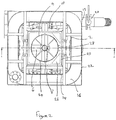
Figure 2 is a plan view of the apparatus ofFigure 1 ; and -
Figure 3 is a longitudinal sectional view of the apparatus ofFigure 1 on line A-A ofFigure 2 . - As illustrated in the drawings, a classification apparatus for classifying and separating sand or similar fine particulate material suspended in a fluid, such as water, for example in the form of a slurry, comprises first and second coaxially arranged
classification tanks tank 2 comprises a vertically arranged tubular housing, having substantially square cross sectional outer wall (although it is envisaged that thefirst tank 2 may have a cylindrical section or other shape). The second (or inner)tank 4 comprises a vertically arranged substantially cylindrical outer wall located coaxially within the first orouter tank 2. The lower end of thesecond tank 4 extends below the lower end of thefirst tank 2. Again, the cross sectional shape of thesecond tank 4 may be other than cylindrical, for example square section. - A
transfer passage 6 extends between the first andsecond tanks first tank 2 and thesecond tank 4. Thetransfer passage 6 comprises a vertically arranged inlet section, extending downwardly into a lower region of thefirst tank 2, an inclined region extending through the side wall of thesecond tank 4 and a vertically arrangedoutlet region 8 extending upwardly and opening into a central or upper region of thesecond tank 4. Preferably theoutlet region 8 of thetransfer passage 6 is aligned with a central axis of thesecond tank 4 such that water and entrained material passes from thefirst tank 2 into thesecond tank 4 in an upwards direction with minimal turbulence. The height of an outlet end of theoutlet region 8 of thetransfer passage 6 may be adjustable, for example by forming theoutlet region 8 from a telescopic section of pipe. A plurality of transfer passages may be provided, in which case the outlet regions of the transfer passages may be equally spaced around the central axis of the second tank. -
Water outlets second tanks tank tank second collection chambers tank water outlets 10 in the first tank is controlled to be less than the flow of water form thewater outlets 12 in the second tank such that the upward water velocity in the first tank is less than that of the second tank, such that the teeter bed in thefirst tank 2 is higher than the teeter bed in thesecond tank 4. This creates a pressure differential between the ends of thetransfer passage 6, causing slurry to flow trough thetransfer passage 6 from thefirst tank 2 to thesecond tank 4. - As shown in
Figure 3 , thewater outlets water outlets - An upper edge of the
first tank 2 defines aperipheral overflow weir 14 over which water and fine entrained solids within thefirst tank 2 may overflow into an annularfirst collection chamber 16 surrounding an upper end of thefirst tank 2. Adrain outlet 18 is provided in thefirst collection chamber 16. A gate valve or otherflow control valve 20 may be provided for controlling the flow through thedrain outlet 18 of thefirst collection chamber 16. As shown inFigure 3 , anupper edge 22 of the outer wall of thefirst collection chamber 16 is higher than theoverflow weir 14 of thefirst tank 2. - Similarly an upper edge of the
second tank 4 defines aperipheral overflow weir 24 over which water and entrained solids within thesecond tank 4 may overflow. Asecond collection chamber 26 having a peripheralouter wall 25 is provided around an upper end of thesecond tank 4, within thefirst tank 2, for receiving water and entrained material passing over theoverflow weir 24 defined by the upper edge of thesecond tank 4. Adrain outlet 28 is provided in a lower region of thesecond collection chamber 26 connected to a downwardlyinclined drain passage 30 extending through thefirst tank 2 and passing through a side wall of thefirst tank 2 to drain the overflow from thesecond tank 4. - A
drain outlet 32 is provided in alower wall 34 of thesecond tank 4 for removing heavier material settling in a lower region of thesecond tank 4, as will be described in more detail below. - In use, a feed slurry is discharged into an upper region of the
first tank 2, for example from a hydrocyclone, via suitable discharge outlets (not shown) while water is supplied to thewater outlets 10 in the lower region of thefirst tank 2, such that water is caused to flow upwardly through the feed slurry within thefirst tank 2. Very fine particulate material (for example 1 - 100 µm) is carried in the upward flow of water in the first tank to pass over theoverflow weir 14 defined by the upper edge of the outer wall of thefirst tank 2 and into thefirst collection chamber 16, from which it is removed as a first cut via thedrain outlet 18 of thefirst collection chamber 16. - Due to the pressure differential between the ends of the transfer pipe, water and heavier entrained particulate material passes through the
transfer pipe 6 from a lower region of thefirst tank 2 and is delivered into a central region of thesecond tank 4 through theoutlet region 8 of thetransfer pipe 6 in an upwards direction, avoiding the creation of turbulence within thesecond tank 4. At the same time water is supplied to thewater outlets 12 in the lower region of thesecond tank 4, creating an upwards flow of water within thesecond tank 4. Heavier particulate material (for example 200µm to 2mm) falls against the flow of water under the action of gravity to settle in a lower region of thesecond tank 4. At the same time, lighter particulate material (for example 100µm to 200µm) is carried in the upward flow of water in thesecond tank 4 to pass over theoverflow weir 24 defined by the upper edge of the outer wall of thesecond tank 4 to pass into thesecond collection chamber 26 surrounding an upper end of thesecond tank 4 to drain therefrom via thedrain outlet 28 thereof as a second cut. - The height of the teeter bed in the
second tank 4 may be controlled via a combination of the flow rate of water from thewater outlets 12 and the flow rate through thedrain outlet 32. Pressure transducers may be provided for determining the fluid pressure a predetermined heights in each of the first and second tanks, such date being fed to a controller, whereby the flow of water to thewater outlets drain outlet 28 may be controlled to control the height of the teeter bed and/or the bed depth of settled solids material in thesecond tank 4. - Control means may be provided for controlling the flow rate of material through the or each
transfer passage 6. Such control means may include a valve within the or each transfer passage of a drain outlet in the first tank. - The heavier particulate material collected in the lower region of the
second tank 4, defining a third cut, is removed from thesecond tank 4 via thedrain outlet 32 in thelower end 34 of thesecond tank 4, for example under the control of a modulating pinch valve. - The invention is not limited to the embodiment(s) described herein but can be amended or modified without departing from the scope of the present invention. While the second tank is described as being co-axially arranged within the first tank, it is envisaged that the first and second tanks may be arranged side by side, the transfer passage extending between the first and second tanks as described above. It is also envisaged that one or more further tanks may be provided, connected in series with one another, respective transfer pipes being provided for passing material between adjacent tanks such that several cuts having different particle size may be provided.
- In an embodiment, which does not form part of the present invention, it is envisaged that a single tank may be provided, feed slurry being introduced into said single tank via one or more inlet pipes, the or each inlet having having an outlet portion extending upwardly within the tank to deliver said feed slurry into the tank in an upwards direction. As with the previous embodiments, water is delivered into a lower region of the tank, whereby water is caused to flow upwardly and through the feed slurry contained therein, whereby hydraulic separation takes place within the at least one tank with particles of lower settling velocity progressing upwardly and into means for effecting discharge of an overflow fraction from the at least one tank, and particles of greater settling velocity progressing downwardly to a lower region of at least one tank to be removed via a drain outlet. The flow rate of the water introduced into the tank is controlled to control the upward velocity of the water within the tank, controlling the cut point of the material in the underflow and overflow of the tank. The flow rate of feed slurry delivered into the tank via the one or more inlet pipes may be controlled as a function of the flow rate of water to minimise turbulence within the tank.
Claims (13)
- An apparatus for classifying particulate material comprising at least one tank (2,4) for receiving a feed slurry, means for introducing water into a lower region of the at least one tank whereby, in use, water is caused to flow upwardly and through the feed slurry contained therein and hydraulic separation takes place within the at least one tank with particles of lower settling velocity progressing upwardly and into a means for effecting discharge of an overflow fraction from the at least one tank, and particles of greater settling velocity progressing downwardly to a lower region of the at least one tank, wherein said feed slurry is introduced into the at least one tank in an upwards direction, said apparatus comprises first and second tanks (2,4), water being introduced into a lower region of each of the first and second tanks (2,4) whereby water is caused to flow upwardly and through a feed slurry contained in each of the first and second tanks, each tank being provided with means for effecting discharge of an overflow fraction therefrom, characterised in that at least one transfer passage (6) is provided for transferring material from the lower region of the first tank (2) to the second tank (4), and in that an outlet region (8) of the at least one transfer passage (6) extends upwardly within the second tank (4) such that feed slurry enters the second tank (4) in an upwards direction to minimise turbulence in the second tank (4).
- An apparatus as claimed in claim 1, wherein the means for introducing water into the first and second tanks is adapted to create a pressure differential between the ends of the or each transfer passage (6) to cause the feed slurry to flow through the at least one transfer passage (6) from the first tank (2) to the second tank (4).
- An apparatus as claimed in claim any preceding claim, wherein at least one further tank is provided downstream of the second tank (4), a feed slurry introducing means of the or each at least one further tank comprising at least one further transfer passage extending from a lower region of an adjacent tank into said at least one further tank, wherein an outlet region of said at least one further transfer passage extends upwardly such that feed slurry enters the at least one further tank in an upwards direction.
- An apparatus as claimed in any preceding claim, wherein the second tank (4) is arranged coaxially within the first tank (2).
- An apparatus as claimed in claim 4, wherein a lower end of the second tank (4) extends below a lower end of the first tank (2).
- An apparatus as claimed in claim 4 or claim 5, wherein an outlet end (8) of the at least one transfer passage (6) is substantially aligned with or, where there are more than one transfer passages, are equally spaced around, a central axis of the second tank (4).
- An apparatus as claimed in any of claims 4 to 6, wherein a peripheral upper edge of first tank (2) defines an outlet weir (14), wherein the overflow fraction of the first tank (2) passes into an annular collection area (16) surrounding an upper region of the first tank (2), wherein the collection area (16) is provided with a drain outlet (18).
- An apparatus as claimed in any preceding claim, wherein the at least one transfer passage (6) is arranged to introduce the feed slurry into the second tank (4) at a predetermined flow rate.
- An apparatus as claimed in claim 8, wherein control means are provided for controlling the flow rate through the at least one transfer passage (6).
- An apparatus as claimed in any preceding claim, wherein the second tank (4) is provided with at least one outlet (32) in a lower region thereof for withdrawing an underflow fraction from said region, control means being provided for controlling the flow rate of said underflow fraction through said outlet (32).
- An apparatus as claimed in any preceding claim, wherein a peripheral upper edge of second tank (4) defines an outlet weir (24), wherein the overflow fraction of the second tank (4) passes into an annular collection area (26) surrounding an upper region of the second tank, said annular collection area (26) of the second tank (4) being provided with a drain outlet (28).
- An apparatus as claimed in any preceding claim, wherein the means for introducing water into the first and second tanks (2,4) comprises a first supply means for delivering water to one or more outlets (10) in a lower region of the first tank (2) and a second supply means for delivering water to one or more outlets (12) in a lower region of the second tank (4), said first and second supply means being independently controllable to independently vary the flow rate of water delivered to each of the first and second tanks (2,4) from the respective outlets (10,12).
- An apparatus as claimed in any preceding claim, wherein the one or more outlets of the means for introducing water into a lower region of the or each tank (2.4) comprise one or more downwardly facing discharge pipes (10,12).
Applications Claiming Priority (1)
| Application Number | Priority Date | Filing Date | Title |
|---|---|---|---|
| GB1420006.7A GB2527381B (en) | 2014-11-10 | 2014-11-10 | Apparatus for classifying particulate material |
Publications (2)
| Publication Number | Publication Date |
|---|---|
| EP3017871A1 EP3017871A1 (en) | 2016-05-11 |
| EP3017871B1 true EP3017871B1 (en) | 2019-06-12 |
Family
ID=52118286
Family Applications (1)
| Application Number | Title | Priority Date | Filing Date |
|---|---|---|---|
| EP15193846.1A Active EP3017871B1 (en) | 2014-11-10 | 2015-11-10 | Apparatus for classifying particulate material |
Country Status (5)
| Country | Link |
|---|---|
| US (1) | US9656270B2 (en) |
| EP (1) | EP3017871B1 (en) |
| AU (1) | AU2015255200B2 (en) |
| GB (1) | GB2527381B (en) |
| ZA (1) | ZA201508264B (en) |
Families Citing this family (1)
| Publication number | Priority date | Publication date | Assignee | Title |
|---|---|---|---|---|
| GB2591466B (en) * | 2020-01-28 | 2022-10-26 | Cde Global Ltd | Apparatus for Classifying Particulate Material |
Family Cites Families (15)
| Publication number | Priority date | Publication date | Assignee | Title |
|---|---|---|---|---|
| US1319208A (en) | 1919-10-21 | Apparatus for separating or concentrating ores | ||
| US170890A (en) * | 1875-12-07 | Improvement in ore-separators | ||
| US45535A (en) * | 1864-12-20 | Improvement in angle-protractors | ||
| US907387A (en) * | 1905-07-10 | 1908-12-22 | Charles W Merrill | Classifier. |
| US982583A (en) * | 1910-07-11 | 1911-01-24 | James N Flood | Hydraulic classifier for ores. |
| US1449603A (en) * | 1919-01-21 | 1923-03-27 | Hokanson Martin | Method of separating granular solid material |
| US1750090A (en) * | 1928-02-25 | 1930-03-11 | Thomas M Chance | Method and apparatus for separating materials of different specific gravities |
| US2418821A (en) * | 1944-12-18 | 1947-04-15 | Coghill William Hawes | Plural stage hydraulic classifier |
| US2679934A (en) * | 1948-12-24 | 1954-06-01 | Hydrotator Company | Apparatus for separating mixed materials |
| US3237773A (en) * | 1960-12-08 | 1966-03-01 | Kamyr Ab | Upright cylindrical container for separating liquor and/or washing cellulosic pulp |
| US3310242A (en) * | 1964-02-24 | 1967-03-21 | Improved Machinery Inc | Fiber disintegrating and classifying apparatus |
| US4222860A (en) * | 1978-06-14 | 1980-09-16 | Park Moon C | Method for the beneficiation of ore |
| US4961843A (en) * | 1989-04-10 | 1990-10-09 | Lewis Robert M | Lewis econosizer for hydraulically classifying particles |
| DE3928369A1 (en) | 1989-08-28 | 1991-03-21 | Gni I Pi Obogasceniju Rud Cvet | Modular concentrator for gravity sepn. - has inclined cylinder with common raw material inlet and light fraction outlet |
| US7147111B2 (en) * | 2003-08-29 | 2006-12-12 | Fendley Brian K | Hindered-settling fluid classifier |
-
2014
- 2014-11-10 GB GB1420006.7A patent/GB2527381B/en active Active
-
2015
- 2015-11-10 ZA ZA201508264A patent/ZA201508264B/en unknown
- 2015-11-10 AU AU2015255200A patent/AU2015255200B2/en active Active
- 2015-11-10 EP EP15193846.1A patent/EP3017871B1/en active Active
- 2015-11-10 US US14/936,954 patent/US9656270B2/en active Active
Non-Patent Citations (1)
| Title |
|---|
| None * |
Also Published As
| Publication number | Publication date |
|---|---|
| EP3017871A1 (en) | 2016-05-11 |
| GB2527381A (en) | 2015-12-23 |
| US9656270B2 (en) | 2017-05-23 |
| GB201420006D0 (en) | 2014-12-24 |
| AU2015255200B2 (en) | 2020-02-20 |
| ZA201508264B (en) | 2019-11-27 |
| AU2015255200A1 (en) | 2016-05-26 |
| US20160129453A1 (en) | 2016-05-12 |
| GB2527381B (en) | 2017-04-26 |
Similar Documents
| Publication | Publication Date | Title |
|---|---|---|
| US20210317009A1 (en) | Method for separating low density particles from feed slurries | |
| US8617405B2 (en) | Separator and method of separation | |
| EP2788121B1 (en) | Deaeration apparatus and method | |
| US20130153472A1 (en) | Apparatus and method for efficient particle to gas bubble attachment in a slurry | |
| US4961843A (en) | Lewis econosizer for hydraulically classifying particles | |
| AU2015299737B2 (en) | An apparatus and method for removing an underflow stream | |
| EP3017871B1 (en) | Apparatus for classifying particulate material | |
| CA3069340A1 (en) | An apparatus and method of feeding a feed slurry into a separating device | |
| EA004660B1 (en) | Method and device for separating fractions in a material flow | |
| US20220062796A1 (en) | Multiphase Separation and Pressure Letdown Method | |
| US3662885A (en) | Apparatus for the hydraulic classification of solids | |
| EP3448576B1 (en) | A feed apparatus for a particle separator, particle separator and method of particle separation | |
| WO2021151769A1 (en) | Apparatus for classifying particulate material | |
| NZ304348A (en) | A separator for separating solids and liquids from a feed material comprises cone shaped tank with feed section having a widened discharge section | |
| OA16263A (en) | Method and apparatus for separating low density particles from feed slurries. |
Legal Events
| Date | Code | Title | Description |
|---|---|---|---|
| PUAI | Public reference made under article 153(3) epc to a published international application that has entered the european phase |
Free format text: ORIGINAL CODE: 0009012 |
|
| AK | Designated contracting states |
Kind code of ref document: A1 Designated state(s): AL AT BE BG CH CY CZ DE DK EE ES FI FR GB GR HR HU IE IS IT LI LT LU LV MC MK MT NL NO PL PT RO RS SE SI SK SM TR |
|
| AX | Request for extension of the european patent |
Extension state: BA ME |
|
| 17P | Request for examination filed |
Effective date: 20160922 |
|
| RBV | Designated contracting states (corrected) |
Designated state(s): AL AT BE BG CH CY CZ DE DK EE ES FI FR GB GR HR HU IE IS IT LI LT LU LV MC MK MT NL NO PL PT RO RS SE SI SK SM TR |
|
| GRAP | Despatch of communication of intention to grant a patent |
Free format text: ORIGINAL CODE: EPIDOSNIGR1 |
|
| STAA | Information on the status of an ep patent application or granted ep patent |
Free format text: STATUS: GRANT OF PATENT IS INTENDED |
|
| INTG | Intention to grant announced |
Effective date: 20181219 |
|
| GRAJ | Information related to disapproval of communication of intention to grant by the applicant or resumption of examination proceedings by the epo deleted |
Free format text: ORIGINAL CODE: EPIDOSDIGR1 |
|
| STAA | Information on the status of an ep patent application or granted ep patent |
Free format text: STATUS: REQUEST FOR EXAMINATION WAS MADE |
|
| GRAR | Information related to intention to grant a patent recorded |
Free format text: ORIGINAL CODE: EPIDOSNIGR71 |
|
| GRAS | Grant fee paid |
Free format text: ORIGINAL CODE: EPIDOSNIGR3 |
|
| STAA | Information on the status of an ep patent application or granted ep patent |
Free format text: STATUS: GRANT OF PATENT IS INTENDED |
|
| GRAA | (expected) grant |
Free format text: ORIGINAL CODE: 0009210 |
|
| STAA | Information on the status of an ep patent application or granted ep patent |
Free format text: STATUS: THE PATENT HAS BEEN GRANTED |
|
| INTC | Intention to grant announced (deleted) | ||
| RBV | Designated contracting states (corrected) |
Designated state(s): AL AT BE BG CH CY CZ DE DK EE ES FI FR GR HR HU IE IS IT LI LT LU LV MC MK MT NL NO PL PT RO RS SE SI SK SM TR |
|
| INTG | Intention to grant announced |
Effective date: 20190429 |
|
| AK | Designated contracting states |
Kind code of ref document: B1 Designated state(s): AL AT BE BG CH CY CZ DE DK EE ES FI FR GR HR HU IE IS IT LI LT LU LV MC MK MT NL NO PL PT RO RS SE SI SK SM TR |
|
| REG | Reference to a national code |
Ref country code: CH Ref legal event code: EP |
|
| REG | Reference to a national code |
Ref country code: AT Ref legal event code: REF Ref document number: 1141909 Country of ref document: AT Kind code of ref document: T Effective date: 20190615 |
|
| REG | Reference to a national code |
Ref country code: DE Ref legal event code: R096 Ref document number: 602015031708 Country of ref document: DE |
|
| REG | Reference to a national code |
Ref country code: IE Ref legal event code: FG4D |
|
| REG | Reference to a national code |
Ref country code: CH Ref legal event code: NV Representative=s name: STOLMAR AND PARTNER INTELLECTUAL PROPERTY S.A., CH |
|
| REG | Reference to a national code |
Ref country code: NL Ref legal event code: MP Effective date: 20190612 |
|
| REG | Reference to a national code |
Ref country code: LT Ref legal event code: MG4D |
|
| REG | Reference to a national code |
Ref country code: NO Ref legal event code: T2 Effective date: 20190612 |
|
| PG25 | Lapsed in a contracting state [announced via postgrant information from national office to epo] |
Ref country code: LT Free format text: LAPSE BECAUSE OF FAILURE TO SUBMIT A TRANSLATION OF THE DESCRIPTION OR TO PAY THE FEE WITHIN THE PRESCRIBED TIME-LIMIT Effective date: 20190612 Ref country code: HR Free format text: LAPSE BECAUSE OF FAILURE TO SUBMIT A TRANSLATION OF THE DESCRIPTION OR TO PAY THE FEE WITHIN THE PRESCRIBED TIME-LIMIT Effective date: 20190612 Ref country code: SE Free format text: LAPSE BECAUSE OF FAILURE TO SUBMIT A TRANSLATION OF THE DESCRIPTION OR TO PAY THE FEE WITHIN THE PRESCRIBED TIME-LIMIT Effective date: 20190612 Ref country code: AL Free format text: LAPSE BECAUSE OF FAILURE TO SUBMIT A TRANSLATION OF THE DESCRIPTION OR TO PAY THE FEE WITHIN THE PRESCRIBED TIME-LIMIT Effective date: 20190612 Ref country code: FI Free format text: LAPSE BECAUSE OF FAILURE TO SUBMIT A TRANSLATION OF THE DESCRIPTION OR TO PAY THE FEE WITHIN THE PRESCRIBED TIME-LIMIT Effective date: 20190612 |
|
| PG25 | Lapsed in a contracting state [announced via postgrant information from national office to epo] |
Ref country code: BG Free format text: LAPSE BECAUSE OF FAILURE TO SUBMIT A TRANSLATION OF THE DESCRIPTION OR TO PAY THE FEE WITHIN THE PRESCRIBED TIME-LIMIT Effective date: 20190912 Ref country code: GR Free format text: LAPSE BECAUSE OF FAILURE TO SUBMIT A TRANSLATION OF THE DESCRIPTION OR TO PAY THE FEE WITHIN THE PRESCRIBED TIME-LIMIT Effective date: 20190913 Ref country code: LV Free format text: LAPSE BECAUSE OF FAILURE TO SUBMIT A TRANSLATION OF THE DESCRIPTION OR TO PAY THE FEE WITHIN THE PRESCRIBED TIME-LIMIT Effective date: 20190612 Ref country code: RS Free format text: LAPSE BECAUSE OF FAILURE TO SUBMIT A TRANSLATION OF THE DESCRIPTION OR TO PAY THE FEE WITHIN THE PRESCRIBED TIME-LIMIT Effective date: 20190612 |
|
| PG25 | Lapsed in a contracting state [announced via postgrant information from national office to epo] |
Ref country code: SK Free format text: LAPSE BECAUSE OF FAILURE TO SUBMIT A TRANSLATION OF THE DESCRIPTION OR TO PAY THE FEE WITHIN THE PRESCRIBED TIME-LIMIT Effective date: 20190612 Ref country code: PT Free format text: LAPSE BECAUSE OF FAILURE TO SUBMIT A TRANSLATION OF THE DESCRIPTION OR TO PAY THE FEE WITHIN THE PRESCRIBED TIME-LIMIT Effective date: 20191014 Ref country code: NL Free format text: LAPSE BECAUSE OF FAILURE TO SUBMIT A TRANSLATION OF THE DESCRIPTION OR TO PAY THE FEE WITHIN THE PRESCRIBED TIME-LIMIT Effective date: 20190612 Ref country code: CZ Free format text: LAPSE BECAUSE OF FAILURE TO SUBMIT A TRANSLATION OF THE DESCRIPTION OR TO PAY THE FEE WITHIN THE PRESCRIBED TIME-LIMIT Effective date: 20190612 Ref country code: RO Free format text: LAPSE BECAUSE OF FAILURE TO SUBMIT A TRANSLATION OF THE DESCRIPTION OR TO PAY THE FEE WITHIN THE PRESCRIBED TIME-LIMIT Effective date: 20190612 Ref country code: EE Free format text: LAPSE BECAUSE OF FAILURE TO SUBMIT A TRANSLATION OF THE DESCRIPTION OR TO PAY THE FEE WITHIN THE PRESCRIBED TIME-LIMIT Effective date: 20190612 |
|
| PG25 | Lapsed in a contracting state [announced via postgrant information from national office to epo] |
Ref country code: SM Free format text: LAPSE BECAUSE OF FAILURE TO SUBMIT A TRANSLATION OF THE DESCRIPTION OR TO PAY THE FEE WITHIN THE PRESCRIBED TIME-LIMIT Effective date: 20190612 Ref country code: ES Free format text: LAPSE BECAUSE OF FAILURE TO SUBMIT A TRANSLATION OF THE DESCRIPTION OR TO PAY THE FEE WITHIN THE PRESCRIBED TIME-LIMIT Effective date: 20190612 Ref country code: IT Free format text: LAPSE BECAUSE OF FAILURE TO SUBMIT A TRANSLATION OF THE DESCRIPTION OR TO PAY THE FEE WITHIN THE PRESCRIBED TIME-LIMIT Effective date: 20190612 Ref country code: IS Free format text: LAPSE BECAUSE OF FAILURE TO SUBMIT A TRANSLATION OF THE DESCRIPTION OR TO PAY THE FEE WITHIN THE PRESCRIBED TIME-LIMIT Effective date: 20191012 |
|
| REG | Reference to a national code |
Ref country code: DE Ref legal event code: R097 Ref document number: 602015031708 Country of ref document: DE |
|
| PG25 | Lapsed in a contracting state [announced via postgrant information from national office to epo] |
Ref country code: TR Free format text: LAPSE BECAUSE OF FAILURE TO SUBMIT A TRANSLATION OF THE DESCRIPTION OR TO PAY THE FEE WITHIN THE PRESCRIBED TIME-LIMIT Effective date: 20190612 |
|
| PLBE | No opposition filed within time limit |
Free format text: ORIGINAL CODE: 0009261 |
|
| STAA | Information on the status of an ep patent application or granted ep patent |
Free format text: STATUS: NO OPPOSITION FILED WITHIN TIME LIMIT |
|
| PG25 | Lapsed in a contracting state [announced via postgrant information from national office to epo] |
Ref country code: PL Free format text: LAPSE BECAUSE OF FAILURE TO SUBMIT A TRANSLATION OF THE DESCRIPTION OR TO PAY THE FEE WITHIN THE PRESCRIBED TIME-LIMIT Effective date: 20190612 Ref country code: DK Free format text: LAPSE BECAUSE OF FAILURE TO SUBMIT A TRANSLATION OF THE DESCRIPTION OR TO PAY THE FEE WITHIN THE PRESCRIBED TIME-LIMIT Effective date: 20190612 |
|
| 26N | No opposition filed |
Effective date: 20200313 |
|
| PG25 | Lapsed in a contracting state [announced via postgrant information from national office to epo] |
Ref country code: IS Free format text: LAPSE BECAUSE OF FAILURE TO SUBMIT A TRANSLATION OF THE DESCRIPTION OR TO PAY THE FEE WITHIN THE PRESCRIBED TIME-LIMIT Effective date: 20200224 Ref country code: SI Free format text: LAPSE BECAUSE OF FAILURE TO SUBMIT A TRANSLATION OF THE DESCRIPTION OR TO PAY THE FEE WITHIN THE PRESCRIBED TIME-LIMIT Effective date: 20190612 |
|
| PG2D | Information on lapse in contracting state deleted |
Ref country code: IS |
|
| PG25 | Lapsed in a contracting state [announced via postgrant information from national office to epo] |
Ref country code: MC Free format text: LAPSE BECAUSE OF FAILURE TO SUBMIT A TRANSLATION OF THE DESCRIPTION OR TO PAY THE FEE WITHIN THE PRESCRIBED TIME-LIMIT Effective date: 20190612 Ref country code: LU Free format text: LAPSE BECAUSE OF NON-PAYMENT OF DUE FEES Effective date: 20191110 |
|
| REG | Reference to a national code |
Ref country code: BE Ref legal event code: MM Effective date: 20191130 |
|
| PG25 | Lapsed in a contracting state [announced via postgrant information from national office to epo] |
Ref country code: BE Free format text: LAPSE BECAUSE OF NON-PAYMENT OF DUE FEES Effective date: 20191130 |
|
| PG25 | Lapsed in a contracting state [announced via postgrant information from national office to epo] |
Ref country code: CY Free format text: LAPSE BECAUSE OF FAILURE TO SUBMIT A TRANSLATION OF THE DESCRIPTION OR TO PAY THE FEE WITHIN THE PRESCRIBED TIME-LIMIT Effective date: 20190612 |
|
| PG25 | Lapsed in a contracting state [announced via postgrant information from national office to epo] |
Ref country code: HU Free format text: LAPSE BECAUSE OF FAILURE TO SUBMIT A TRANSLATION OF THE DESCRIPTION OR TO PAY THE FEE WITHIN THE PRESCRIBED TIME-LIMIT; INVALID AB INITIO Effective date: 20151110 Ref country code: MT Free format text: LAPSE BECAUSE OF FAILURE TO SUBMIT A TRANSLATION OF THE DESCRIPTION OR TO PAY THE FEE WITHIN THE PRESCRIBED TIME-LIMIT Effective date: 20190612 |
|
| REG | Reference to a national code |
Ref country code: AT Ref legal event code: UEP Ref document number: 1141909 Country of ref document: AT Kind code of ref document: T Effective date: 20190612 |
|
| PG25 | Lapsed in a contracting state [announced via postgrant information from national office to epo] |
Ref country code: MK Free format text: LAPSE BECAUSE OF FAILURE TO SUBMIT A TRANSLATION OF THE DESCRIPTION OR TO PAY THE FEE WITHIN THE PRESCRIBED TIME-LIMIT Effective date: 20190612 |
|
| PGFP | Annual fee paid to national office [announced via postgrant information from national office to epo] |
Ref country code: NO Payment date: 20221123 Year of fee payment: 8 |
|
| P01 | Opt-out of the competence of the unified patent court (upc) registered |
Effective date: 20230530 |
|
| PGFP | Annual fee paid to national office [announced via postgrant information from national office to epo] |
Ref country code: IE Payment date: 20231002 Year of fee payment: 9 Ref country code: FR Payment date: 20231120 Year of fee payment: 9 Ref country code: DE Payment date: 20231121 Year of fee payment: 9 Ref country code: CH Payment date: 20231201 Year of fee payment: 9 Ref country code: AT Payment date: 20231121 Year of fee payment: 9 |