EP3017640B1 - System and method for cooperative precoding in heterogenous two-tier wireless networks - Google Patents
System and method for cooperative precoding in heterogenous two-tier wireless networks Download PDFInfo
- Publication number
- EP3017640B1 EP3017640B1 EP14834914.5A EP14834914A EP3017640B1 EP 3017640 B1 EP3017640 B1 EP 3017640B1 EP 14834914 A EP14834914 A EP 14834914A EP 3017640 B1 EP3017640 B1 EP 3017640B1
- Authority
- EP
- European Patent Office
- Prior art keywords
- ctp
- network
- tier
- tier network
- cooperative
- Prior art date
- Legal status (The legal status is an assumption and is not a legal conclusion. Google has not performed a legal analysis and makes no representation as to the accuracy of the status listed.)
- Active
Links
- 238000000034 method Methods 0.000 title claims description 30
- 239000011159 matrix material Substances 0.000 claims description 35
- 230000005540 biological transmission Effects 0.000 claims description 20
- 238000004891 communication Methods 0.000 claims description 11
- 239000013256 coordination polymer Substances 0.000 claims description 4
- 125000004122 cyclic group Chemical group 0.000 claims description 3
- 238000000354 decomposition reaction Methods 0.000 claims description 2
- 208000000649 small cell carcinoma Diseases 0.000 description 16
- 238000012545 processing Methods 0.000 description 15
- 239000013598 vector Substances 0.000 description 15
- 230000015654 memory Effects 0.000 description 9
- 230000001413 cellular effect Effects 0.000 description 5
- 230000008569 process Effects 0.000 description 4
- 238000010586 diagram Methods 0.000 description 2
- 241000053227 Themus Species 0.000 description 1
- 239000000654 additive Substances 0.000 description 1
- 230000000996 additive effect Effects 0.000 description 1
- 230000004075 alteration Effects 0.000 description 1
- 238000004364 calculation method Methods 0.000 description 1
- 238000010276 construction Methods 0.000 description 1
- 238000013500 data storage Methods 0.000 description 1
- 238000013461 design Methods 0.000 description 1
- 230000010354 integration Effects 0.000 description 1
- 230000002452 interceptive effect Effects 0.000 description 1
- 238000013507 mapping Methods 0.000 description 1
- 230000006855 networking Effects 0.000 description 1
- 230000003287 optical effect Effects 0.000 description 1
- 230000002093 peripheral effect Effects 0.000 description 1
- 238000012805 post-processing Methods 0.000 description 1
- 230000004044 response Effects 0.000 description 1
- 239000007787 solid Substances 0.000 description 1
- 230000003595 spectral effect Effects 0.000 description 1
- 230000003068 static effect Effects 0.000 description 1
- 238000006467 substitution reaction Methods 0.000 description 1
- 230000001360 synchronised effect Effects 0.000 description 1
- 239000002699 waste material Substances 0.000 description 1
Images

Classifications
-
- H—ELECTRICITY
- H04—ELECTRIC COMMUNICATION TECHNIQUE
- H04L—TRANSMISSION OF DIGITAL INFORMATION, e.g. TELEGRAPHIC COMMUNICATION
- H04L25/00—Baseband systems
- H04L25/02—Details ; arrangements for supplying electrical power along data transmission lines
- H04L25/03—Shaping networks in transmitter or receiver, e.g. adaptive shaping networks
- H04L25/03891—Spatial equalizers
- H04L25/03898—Spatial equalizers codebook-based design
- H04L25/03904—Spatial equalizers codebook-based design cooperative design, e.g. exchanging of codebook information between base stations
-
- H—ELECTRICITY
- H04—ELECTRIC COMMUNICATION TECHNIQUE
- H04B—TRANSMISSION
- H04B7/00—Radio transmission systems, i.e. using radiation field
- H04B7/02—Diversity systems; Multi-antenna system, i.e. transmission or reception using multiple antennas
- H04B7/022—Site diversity; Macro-diversity
- H04B7/024—Co-operative use of antennas of several sites, e.g. in co-ordinated multipoint or co-operative multiple-input multiple-output [MIMO] systems
-
- H—ELECTRICITY
- H04—ELECTRIC COMMUNICATION TECHNIQUE
- H04L—TRANSMISSION OF DIGITAL INFORMATION, e.g. TELEGRAPHIC COMMUNICATION
- H04L25/00—Baseband systems
- H04L25/02—Details ; arrangements for supplying electrical power along data transmission lines
- H04L25/0264—Arrangements for coupling to transmission lines
- H04L25/028—Arrangements specific to the transmitter end
-
- H—ELECTRICITY
- H04—ELECTRIC COMMUNICATION TECHNIQUE
- H04J—MULTIPLEX COMMUNICATION
- H04J11/00—Orthogonal multiplex systems, e.g. using WALSH codes
- H04J11/0023—Interference mitigation or co-ordination
-
- H—ELECTRICITY
- H04—ELECTRIC COMMUNICATION TECHNIQUE
- H04J—MULTIPLEX COMMUNICATION
- H04J11/00—Orthogonal multiplex systems, e.g. using WALSH codes
- H04J11/0023—Interference mitigation or co-ordination
- H04J11/005—Interference mitigation or co-ordination of intercell interference
- H04J11/0056—Inter-base station aspects
-
- H—ELECTRICITY
- H04—ELECTRIC COMMUNICATION TECHNIQUE
- H04L—TRANSMISSION OF DIGITAL INFORMATION, e.g. TELEGRAPHIC COMMUNICATION
- H04L25/00—Baseband systems
- H04L25/02—Details ; arrangements for supplying electrical power along data transmission lines
- H04L25/03—Shaping networks in transmitter or receiver, e.g. adaptive shaping networks
- H04L25/03006—Arrangements for removing intersymbol interference
- H04L25/03343—Arrangements at the transmitter end
-
- H—ELECTRICITY
- H04—ELECTRIC COMMUNICATION TECHNIQUE
- H04L—TRANSMISSION OF DIGITAL INFORMATION, e.g. TELEGRAPHIC COMMUNICATION
- H04L25/00—Baseband systems
- H04L25/02—Details ; arrangements for supplying electrical power along data transmission lines
- H04L25/0202—Channel estimation
- H04L25/0204—Channel estimation of multiple channels
Definitions
- the present invention relates to the field of wireless communications, and, in particular embodiments, to a system and method for cooperative precoding in two-tier cellular networks.
- Two-tier networks comprise a conventional cellular network overlaid with shorter range second-tier networks or hotspots, also referred to as small-cells, such as using femto-cells, distributed antennas, or relays.
- second-tier networks have priorities and can allow some level of interference to the primary systems, e.g. conventional cellular networks or macro-cells.
- Other second-tier systems can opportunistically transmit without interfering with existing primary systems.
- Such opportunistic two-tier systems include the so-called Vandermonde frequency Division Multiple Access (VFDM) systems which allow the coexistence of a macro-cell comprising multiple primary users and a small-cell comprising multiple secondary user pairs.
- VFDM Vandermonde frequency Division Multiple Access
- precoding at small-cell transmitters causes no interference to the macro-cell.
- a drawback of such systems is that precoding at the small-cell transmitters is carried out independently, thereby causing a waste of extra transmit dimensions as well as low efficiency linear precoding due to dimension restriction.
- An improved precoding scheme for two-tier cellular networks is needed.
- a method for reducing interference or avoiding signal interference in a first tier network from a second tier network and within the second tier network includes receiving, by the network device from a user device in the first tier network, channel state information (CSI) of signals received by the user device in the first tier network from the transmitter devices in the second tier network, performing cooperative cross-tier precoding (CTP) for transmit signals of transmitter devices in the second tier network, wherein the performing the cooperative CTP includes performing the cooperative CTP in accordance with the CSI, generating CTP matrix information in accordance with the performed cooperative CTP, and performing intra-tier precoding (ITP) for the transmit signals in accordance with the CTP matrix information, wherein the performing the ITP includes performing the ITP in accordance with the CSI.
- the method further includes forwarding information about the cooperative CTP and ITP to the transmitter devices in the second tier network.
- An apparatus for performing this method is also provided.
- a network component adapted to reduce or avoid signal interference in a first tier network from a second tier network and in a second tier network.
- the network component comprises a transmitter, and a processor communicatively connected to the transmitter.
- the processor is configured to perform both cooperative cross-tier precoding (CTP) and intra-tier precoding (ITP) for transmit signals of transmitter devices in the second tier network.
- the processor performs the ITP with consideration of information generated from the cooperative CTP.
- the transmitter is configured to send information about the cooperative CTP and ITP to the transmitter devices in the second tier network.
- the cooperative CTP and ITP are performed in accordance with a channel state information, CSI, of signals received by a user device in the first tier network from the transmitter devices in the second tier network.
- CSI channel state information
- the network component includes a transmitter and a processor communicatively connected to the transmitter.
- the processor is configured to perform both a first precoding and a second precoding for transmitter devices in the second tier network.
- the processor performs the first pre-coding to reduce or cancel interference in the first tier network caused by transmissions of the transmitter devices in the second tier network.
- the processor performs the second pre-coding in accordance with information generated from the first precoding to reduce or cancel intra-signal interference in the second tier network caused by the transmissions from transmitter devices in the second tier network.
- the transmitter is configured to forward information about the first precoding and the second precoding to the transmitter devices in the second tier network.
- Embodiments are provided herein for a cooperative cross-tier and intra-tier precoding scheme for two-tier networks, e.g., using multi-user Vandermonde Frequency Division Multiple Access (MU-VFDM).
- the cooperative precoding scheme allows exploitation of extra transmit dimensions at the second-tier network, thereby increasing the achievable throughput at the second-tier network (or the small-cell).
- the embodiments allow significant increase in throughput of the second-tier network or small-cells due to both cross precoding between the small-cell and the macro-cell, referred to herein as cross-tier precoding (CTP), and efficient intra-precoding between the small-cell transmitters, referred to herein as intra-tier precoding (ITP).
- Cooperative CTP for the small-cell transmitters allows for increase in the transmit dimensions, thus significantly improving the throughput of the second-tier network or small-cell.
- the transmit dimension increase allows for efficient linear inra-tier precoding, which significantly reduces the intra-tier interference.
- Figure 1 shows a two-tier network or system 100 comprising a macro-cell (MC) 110 (e.g., as in conventional cellular networks) and a second-tier network or small-cell (SC) 120.
- the MC 110 comprises a MC bases station (MBS) 112 and M MC user devices (MUs) 114, where M is an integer. Examples of user devices include smartphones, computers (e.g., desktops, laptops, tablets), or any other communication devices.
- the MBS 112 and M MUs 114 may communicate using orthogonal frequency-division multiplexing (OFDM) or OFDM Access (OFDMA) transmissions.
- OFDM orthogonal frequency-division multiplexing
- OFDMA OFDM Access
- the SC 120 comprises K SC access points (SAPs) 122 (e.g., femto-cells, distributed antennas, relays) and K SC user devices (SUs) 124, where K is an integer.
- the SUs 124 may be similar to the MUs 114.
- the K APs 122 and K MUs 114 may communicate using MU-VFDM transmissions.
- the K SAPs 122 may communicate with K respective SUs 124 in pairs (e.g., each SAP 122 communicates with one corresponding SU 124).
- multiple pairs of UEs may communicate with each other (e.g., in UE to UE communications) via device-to-device (D2D) communications.
- D2D device-to-device
- the channels or signals precoded for signal avoidance correspond to the transmissions in the pairs of UEs without SAPs.
- a precoder (not shown) is used in the two-tier network or system 100 to pre-process the transmit signal at the SAPs 122 so that the transmitted signal vector from the SAPs 122, x S , generates no interference to the received signal vector at the considered MU, y M .
- the cross-tier precoder may be located at or away from the SC 120, and is coupled to the SAPs 122, for example any suitable wired or wireless connections.
- the precoder may have knowledge of channel state information (CSI) for channels or transmissions from the SAPs 122 to each considered MU 114, CSI for transmissions from the SAPs 122 to the SUs 124, and CSI for transmissions from the MBS 112 to the SUs 124. This knowledge is used in the cooperative CTP, such as to generate the matrices and vectors for the different calculations below.
- CSI channel state information
- the overall transmit dimension (or the number of overall symbols transmitted by K SAPs 122), J , is equal to KL (the product of the number of SAPs 122 and the CP length).
- KL the product of the number of SAPs 122 and the CP length.
- the overall transmit dimension, J can be greatly increased and the capacity of VFDM transmission is improved accordingly.
- increase of the overall transmit dimension allows to use more efficient ITP to cancel inter-SAP interference, as described below.
- the precoder is further configured for cooperative CTP, where the generated CTP matrix, E, is not necessarily diagonal.
- H SM U ⁇ V H , where U and V are both unitary, and A is diagonal.
- the transmitted signal of the new link uses the null space of the existing link.
- the same precoder or a second precoder implements ITP to cancel inter-SAP interference from the SAPs 122 to the SUs 124.
- the ITP process may also use the knowledge of CSI for channels or transmissions from the SAPs 122 to each considered MU 114, CSI for transmissions from the SAPs 122 to the SUs 124, and CSI for transmissions from the MBS 112 to the SUs 124.
- the ITP is implemented in conjunction with the CTP process above.
- the size of H SS depends on the CTP used. For non-cooperative CTP, the size of H SS is KN ⁇ KL. In this case, the overall transmit dimension is always less than the overall receive dimension since L ⁇ N. As a result, a matched filter (MF) is used as ITP.
- MF matched filter
- H SS becomes a matrix with size KN ⁇ [( K -1) N+KL ] matrix.
- the overall transmit dimension is larger than the overall receive dimension, allowing the use of zero forcing (ZF), which is a more efficient precoding than MF.
- ZF zero forcing
- the ITP may be implemented using a minimum mean square error (MMSE) precoder or any other non-linear precoding type.
- MMSE minimum mean square error
- the inter-SAP interference is canceled using block diagonal (BD)-ZF.
- the interference from other SAPs 122 is canceled at a considered k th SU 124 while the self-interference, e.g., inter-symbol interference, can be handled by the kth SU 124.
- BD-ZF a water-filling algorithm may also be implemented to optimize or improve power allocation of transmit signals at each of the APs.
- the BD-ZF based ITP may use statistical properties of interference and noise.
- a capacity-achieving ITP can be designed using the correlation matrix of interference to whiten the channel. SVD of the equivalent channel can then be implemented to design the ITP.
- the inter-SAP interference is canceled using a complete-diagonal ZF, which can cancel both inter-SAP interference and self-interference at the SU 124. In this case, no additional processing is required at each individual SU 124.
- complete diagonal-ZF can simplify the receiver structure, it may reduce the throughput or requires higher power at the transmitter.
- BD-ZF may not be possible when KN >[( K - 1) N + KL ].
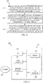
- Figure 2 shows an embodiment of a cooperative cross-tier and intra-tier precoding method 200 for a tow-tier network or system, such as the tow-tier network or system 100.
- the method 200 can be implemented by one or more precoders located at the network/system or at a remote location and coupled to the SAPs in the system (e.g., the SAPs 122) of the small-cell and possibly to a MBS (e.g., MBS 112) of the macro-cell.
- the precoders are coupled to transmitting UEs in communications with corresponding receiver UEs via D2D communications.
- the precoder(s) receive(s) CSI for transmissions from a plurality of SAPs (or transmitting UEs) to a considered MU, CSI for channels or transmissions from the SAPs to a plurality of SUs (or receiver UEs), and CSI for transmissions from the MBS to the SUs (or receiver UEs).
- the precoder(s) perform(s) CTP for cancelling signal interference from the SAPs (or transmitter UEs) to the considered MU.
- the precoder(s) perfom(s) in cooperation with the CTP, ITP for cancelling or reducing signal interference from the SAPs (or transmitter UEs) to the SUs (or receiver UEs).
- the ITP includes using the CTP matrix generated in the cooperative CTP for the SAPs (or transmitter UEs).
- FIG. 3 is a block diagram of an exemplary processing system 300 that can be used to implement various embodiments. Specific devices may utilize all of the components shown, or only a subset of the components and levels of integration may vary from device to device. Furthermore, a device may contain multiple instances of a component, such as multiple processing units, processors, memories, transmitters, receivers, etc.
- the processing system 300 may comprise a processing unit 301 equipped with one or more input/output devices, such as a network interfaces, storage interfaces, and the like.
- the processing unit 301 may include a central processing unit (CPU) 310, a memory 320, a mass storage device 330, and an I/O interface 360 connected to a bus.
- the bus may be one or more of any type of several bus architectures including a memory bus or memory controller, a peripheral bus or the like.
- the CPU 310 may comprise any type of electronic data processor.
- the memory 320 may comprise any type of system memory such as static random access memory (SRAM), dynamic random access memory (DRAM), synchronous DRAM (SDRAM), read-only memory (ROM), a combination thereof, or the like.
- the memory 320 may include ROM for use at boot-up, and DRAM for program and data storage for use while executing programs.
- the memory 320 is non-transitory.
- the mass storage device 330 may comprise any type of storage device configured to store data, programs, and other information and to make the data, programs, and other information accessible via the bus.
- the mass storage device 330 may comprise, for example, one or more of a solid state drive, hard disk drive, a magnetic disk drive, an optical disk drive, or the like.
- the processing unit 301 also includes one or more network interfaces 350, which may comprise wired links, such as an Ethernet cable or the like, or wireless links to access nodes or one or more networks 380.
- the network interface 350 allows the processing unit 301 to communicate with remote units via the networks 380.
- the network interface 350 may provide wireless communication via one or more transmitters/transmit antennas and one or more receivers/receive antennas.
- the processing unit 301 is coupled to a local-area network or a wide-area network for data processing and communications with remote devices, such as other processing units, the Internet, remote storage facilities, or the like.
Description
- The present invention relates to the field of wireless communications, and, in particular embodiments, to a system and method for cooperative precoding in two-tier cellular networks.
- Two-tier networks comprise a conventional cellular network overlaid with shorter range second-tier networks or hotspots, also referred to as small-cells, such as using femto-cells, distributed antennas, or relays. Such coexisting systems can increase spectral efficiency for serving users. Some second-tier systems have priorities and can allow some level of interference to the primary systems, e.g. conventional cellular networks or macro-cells. Other second-tier systems can opportunistically transmit without interfering with existing primary systems. Such opportunistic two-tier systems include the so-called Vandermonde frequency Division Multiple Access (VFDM) systems which allow the coexistence of a macro-cell comprising multiple primary users and a small-cell comprising multiple secondary user pairs. In VFDM, precoding at small-cell transmitters causes no interference to the macro-cell. However, a drawback of such systems is that precoding at the small-cell transmitters is carried out independently, thereby causing a waste of extra transmit dimensions as well as low efficiency linear precoding due to dimension restriction. An improved precoding scheme for two-tier cellular networks is needed.
- In a related field, Marco Maso et al: "Channel Estimation Impact for LTE Small Cells based on MU-VFDM", 2012 IEEE Wireless Communications and Networking Conference (WCNC), 1 April 2012, pages 2560-2565 discloses interference cancellation for a system model in which macro cells and small cells share a frequency band. An individual precoder Ei is computed disjointly by each small cell access point, based on its own link quality to the macro cell user equipments.
- In accordance with an aspect of the present invention, a method for reducing interference or avoiding signal interference in a first tier network from a second tier network and within the second tier network is provided. In this example, the method includes receiving, by the network device from a user device in the first tier network, channel state information (CSI) of signals received by the user device in the first tier network from the transmitter devices in the second tier network, performing cooperative cross-tier precoding (CTP) for transmit signals of transmitter devices in the second tier network, wherein the performing the cooperative CTP includes performing the cooperative CTP in accordance with the CSI, generating CTP matrix information in accordance with the performed cooperative CTP, and performing intra-tier precoding (ITP) for the transmit signals in accordance with the CTP matrix information, wherein the performing the ITP includes performing the ITP in accordance with the CSI. The method further includes forwarding information about the cooperative CTP and ITP to the transmitter devices in the second tier network. An apparatus for performing this method is also provided.
- In accordance with another aspect of the present invention, a network component adapted to reduce or avoid signal interference in a first tier network from a second tier network and in a second tier network is provided. In this example, the network component comprises a transmitter, and a processor communicatively connected to the transmitter. The processor is configured to perform both cooperative cross-tier precoding (CTP) and intra-tier precoding (ITP) for transmit signals of transmitter devices in the second tier network. The processor performs the ITP with consideration of information generated from the cooperative CTP. The transmitter is configured to send information about the cooperative CTP and ITP to the transmitter devices in the second tier network. The cooperative CTP and ITP are performed in accordance with a channel state information, CSI, of signals received by a user device in the first tier network from the transmitter devices in the second tier network.
- In accordance with yet another aspect of the present invention, another network component adapted to reduce or avoid signal interference in a first tier network from a second tier network and in a second tier network is provided. In this example, the network component includes a transmitter and a processor communicatively connected to the transmitter. The processor is configured to perform both a first precoding and a second precoding for transmitter devices in the second tier network. The processor performs the first pre-coding to reduce or cancel interference in the first tier network caused by transmissions of the transmitter devices in the second tier network. The processor performs the second pre-coding in accordance with information generated from the first precoding to reduce or cancel intra-signal interference in the second tier network caused by the transmissions from transmitter devices in the second tier network. The transmitter is configured to forward information about the first precoding and the second precoding to the transmitter devices in the second tier network.
- The foregoing has outlined rather broadly the features of an embodiment of the present invention in order that the detailed description of the invention that follows may be better understood. Additional features and advantages of embodiments of the invention will be described hereinafter, which form the subject of the claims of the invention. It should be appreciated by those skilled in the art that the conception and specific embodiments disclosed may be readily utilized as a basis for modifying or designing other structures or processes for carrying out the same purposes of the present invention. It should also be realized by those skilled in the art that such equivalent constructions do not depart from the scope of the invention as set forth in the appended claims.
- For a more complete understanding of the present invention, and the advantages thereof, reference is now made to the following descriptions taken in conjunction with the accompanying drawing, in which:
-
Figure 1 illustrates an example of a two-tier network or system; -
Figure 2 illustrates an embodiment of a cooperative cross-tier and intra-tier precoding method for a tow-tier network or system; and -
Figure 3 illustrates a diagram of an embodiment processing system that can be used to implement various embodiments. - Corresponding numerals and symbols in the different figures generally refer to corresponding parts unless otherwise indicated. The figures are drawn to clearly illustrate the relevant aspects of the embodiments and are not necessarily drawn to scale.
- The making and using of the presently preferred embodiments are discussed in detail below. It should be appreciated, however, that the present invention provides many applicable inventive concepts that can be embodied in a wide variety of specific contexts. The specific embodiments discussed are merely illustrative of specific ways to make and use the invention, and do not limit the scope of the invention.
- Embodiments are provided herein for a cooperative cross-tier and intra-tier precoding scheme for two-tier networks, e.g., using multi-user Vandermonde Frequency Division Multiple Access (MU-VFDM). The cooperative precoding scheme allows exploitation of extra transmit dimensions at the second-tier network, thereby increasing the achievable throughput at the second-tier network (or the small-cell). The embodiments allow significant increase in throughput of the second-tier network or small-cells due to both cross precoding between the small-cell and the macro-cell, referred to herein as cross-tier precoding (CTP), and efficient intra-precoding between the small-cell transmitters, referred to herein as intra-tier precoding (ITP). Cooperative CTP for the small-cell transmitters allows for increase in the transmit dimensions, thus significantly improving the throughput of the second-tier network or small-cell. The transmit dimension increase allows for efficient linear inra-tier precoding, which significantly reduces the intra-tier interference.
-
Figure 1 shows a two-tier network orsystem 100 comprising a macro-cell (MC) 110 (e.g., as in conventional cellular networks) and a second-tier network or small-cell (SC) 120. The MC 110 comprises a MC bases station (MBS) 112 and M MC user devices (MUs) 114, where M is an integer. Examples of user devices include smartphones, computers (e.g., desktops, laptops, tablets), or any other communication devices. TheMBS 112 andM MUs 114 may communicate using orthogonal frequency-division multiplexing (OFDM) or OFDM Access (OFDMA) transmissions. The SC 120 comprises K SC access points (SAPs) 122 (e.g., femto-cells, distributed antennas, relays) and K SC user devices (SUs) 124, where K is an integer. The SUs 124 may be similar to theMUs 114. TheK APs 122 and KMUs 114 may communicate using MU-VFDM transmissions. TheK SAPs 122 may communicate with Krespective SUs 124 in pairs (e.g., eachSAP 122 communicates with one corresponding SU 124). In another embodiment, multiple pairs of UEs may communicate with each other (e.g., in UE to UE communications) via device-to-device (D2D) communications. In this case, the channels or signals precoded for signal avoidance (as discussed below) correspond to the transmissions in the pairs of UEs without SAPs. - Considering, for instance, an OFDM transmission (e.g., on downlink for
MC 110 and SC 120) with N subcarriers and a cyclic (CP) length of L used inMC 110, the received vector yM at a considered Mth MU 114 is represented as:
MBS 112, H SM is the overall cross-channel matrix fromSAPs 122 to the consideredMU 114, and x S is the overall transmitted signal vector from theSAPs 122. The overall transmitted signal vector from theSAPs 122 can be expressed as:
- The overall cross-channel matrix from the
SAPs 122 can be expressed as:
- Additionally, a precoder (not shown) is used in the two-tier network or
system 100 to pre-process the transmit signal at theSAPs 122 so that the transmitted signal vector from theSAPs 122, x S, generates no interference to the received signal vector at the considered MU, y M. The cross-tier precoder may be located at or away from the SC 120, and is coupled to theSAPs 122, for example any suitable wired or wireless connections. The precoder may have knowledge of channel state information (CSI) for channels or transmissions from theSAPs 122 to each consideredMU 114, CSI for transmissions from theSAPs 122 to theSUs 124, and CSI for transmissions from theMBS 112 to theSUs 124. This knowledge is used in the cooperative CTP, such as to generate the matrices and vectors for the different calculations below. - At the precoder, a transmitted signal vector from the
SAPs 112 can be expressed as:
SAPs 122, and s S is the transmitted symbol vector. If CTP is performed independently at eachindividual SAP 122, the overall transmit dimension (or the number of overall symbols transmitted by K SAPs 122), J, is equal to KL (the product of the number ofSAPs 122 and the CP length). However, using cooperation among theSAPs 122, the overall transmit dimension, J, can be greatly increased and the capacity of VFDM transmission is improved accordingly. In addition, increase of the overall transmit dimension allows to use more efficient ITP to cancel inter-SAP interference, as described below. - The precoder is further configured for cooperative CTP, where the generated CTP matrix, E, is not necessarily diagonal. The generated matrix, E, by the precoder can be any matrix for cancelling interference caused by
SAPs 122 in theSC 110, which satisfies the following:
- Specifically, a single value decomposition (SVD) is applied on the channel matrix, H SM, to obtain:


- This SVD assumes the diagonal matrix, Σ, is full rank. In this case, the overall transmit dimension is J = (K - 1)N+KL. This means that, using the cooperative CTP, (K - 1)N+KL symbols can be transmitted from the
K SAPs 122, e.g., in comparison to only KL symbols if the CTP is performed independently at each of the Kindividual SAPs 122. The extra (K - 1)N dimensions result from the exploitation of cooperative CTP for theSAPs 122. - Based on the operations at the existing link, the interference signal at the existing receiver after post-processing can also be expressed as


- As such, if the power allocation of the primary system (first-tier network) is known, more symbols can be transmitted from the secondary system (second tier-network).
- Additionally, the same precoder or a second precoder implements ITP to cancel inter-SAP interference from the
SAPs 122 to theSUs 124. The ITP process may also use the knowledge of CSI for channels or transmissions from theSAPs 122 to each consideredMU 114, CSI for transmissions from theSAPs 122 to theSUs 124, and CSI for transmissions from theMBS 112 to theSUs 124. The ITP is implemented in conjunction with the CTP process above. For ITP, the overall received vector at the SUs is expressed as:
SUs 124 and additive noise plus interference from theMBS 112 at theSUs 124, respectively, and H SS is the overall equivalent channel matrix. - Specifically, ITP processing takes into account the cooperative CTP processing using x S = Es S from (4). Accordingly, the overall receive signal vector at the
SAPs 124 can be expressed as:
H SS= H SS E, E being the generated CTP matrix above. The size ofH SS depends on the CTP used. For non-cooperative CTP, the size ofH SS is KN × KL. In this case, the overall transmit dimension is always less than the overall receive dimension since L < N. As a result, a matched filter (MF) is used as ITP. However using cooperative CTP in thesystem 100, as described above,H SS becomes a matrix with size KN≤[(K-1)N+KL] matrix. Thus, the overall transmit dimension is larger than the overall receive dimension, allowing the use of zero forcing (ZF), which is a more efficient precoding than MF. In other embodiments, the ITP may be implemented using a minimum mean square error (MMSE) precoder or any other non-linear precoding type. - In one implementation, the inter-SAP interference is canceled using block diagonal (BD)-ZF. In this case, the interference from
other SAPs 122 is canceled at a considered kth SU 124 while the self-interference, e.g., inter-symbol interference, can be handled by thekth SU 124. In the case of using BD-ZF, a water-filling algorithm may also be implemented to optimize or improve power allocation of transmit signals at each of the APs. The BD-ZF based ITP may use statistical properties of interference and noise. A capacity-achieving ITP can be designed using the correlation matrix of interference to whiten the channel. SVD of the equivalent channel can then be implemented to design the ITP. In another implementation, the inter-SAP interference is canceled using a complete-diagonal ZF, which can cancel both inter-SAP interference and self-interference at theSU 124. In this case, no additional processing is required at eachindividual SU 124. Although complete diagonal-ZF can simplify the receiver structure, it may reduce the throughput or requires higher power at the transmitter. Unlike complete-diagonal ZF, BD-ZF may not be possible when KN>[(K- 1)N+KL]. -
Figure 2 shows an embodiment of a cooperative cross-tier andintra-tier precoding method 200 for a tow-tier network or system, such as the tow-tier network orsystem 100. Themethod 200 can be implemented by one or more precoders located at the network/system or at a remote location and coupled to the SAPs in the system (e.g., the SAPs 122) of the small-cell and possibly to a MBS (e.g., MBS 112) of the macro-cell. Alternatively, the precoders are coupled to transmitting UEs in communications with corresponding receiver UEs via D2D communications. Atstep 210, the precoder(s) receive(s) CSI for transmissions from a plurality of SAPs (or transmitting UEs) to a considered MU, CSI for channels or transmissions from the SAPs to a plurality of SUs (or receiver UEs), and CSI for transmissions from the MBS to the SUs (or receiver UEs). Atstep 220, the precoder(s) perform(s) CTP for cancelling signal interference from the SAPs (or transmitter UEs) to the considered MU. The cooperative CTP for the SAPs (or transmitter UEs) generates a non-diagonal CTP matrix with increased transmit dimension, J, e.g., allowing for transmission of up to J = (K - 1)N+KL symbols. Atstep 230, the precoder(s) perfom(s), in cooperation with the CTP, ITP for cancelling or reducing signal interference from the SAPs (or transmitter UEs) to the SUs (or receiver UEs). The ITP includes using the CTP matrix generated in the cooperative CTP for the SAPs (or transmitter UEs). -
Figure 3 is a block diagram of anexemplary processing system 300 that can be used to implement various embodiments. Specific devices may utilize all of the components shown, or only a subset of the components and levels of integration may vary from device to device. Furthermore, a device may contain multiple instances of a component, such as multiple processing units, processors, memories, transmitters, receivers, etc. Theprocessing system 300 may comprise aprocessing unit 301 equipped with one or more input/output devices, such as a network interfaces, storage interfaces, and the like. Theprocessing unit 301 may include a central processing unit (CPU) 310, amemory 320, amass storage device 330, and an I/O interface 360 connected to a bus. The bus may be one or more of any type of several bus architectures including a memory bus or memory controller, a peripheral bus or the like. - The
CPU 310 may comprise any type of electronic data processor. Thememory 320 may comprise any type of system memory such as static random access memory (SRAM), dynamic random access memory (DRAM), synchronous DRAM (SDRAM), read-only memory (ROM), a combination thereof, or the like. In an embodiment, thememory 320 may include ROM for use at boot-up, and DRAM for program and data storage for use while executing programs. In embodiments, thememory 320 is non-transitory. Themass storage device 330 may comprise any type of storage device configured to store data, programs, and other information and to make the data, programs, and other information accessible via the bus. Themass storage device 330 may comprise, for example, one or more of a solid state drive, hard disk drive, a magnetic disk drive, an optical disk drive, or the like. - The
processing unit 301 also includes one ormore network interfaces 350, which may comprise wired links, such as an Ethernet cable or the like, or wireless links to access nodes or one ormore networks 380. Thenetwork interface 350 allows theprocessing unit 301 to communicate with remote units via thenetworks 380. For example, thenetwork interface 350 may provide wireless communication via one or more transmitters/transmit antennas and one or more receivers/receive antennas. In an embodiment, theprocessing unit 301 is coupled to a local-area network or a wide-area network for data processing and communications with remote devices, such as other processing units, the Internet, remote storage facilities, or the like. - While several embodiments have been provided in the present disclosure, it should be understood that the disclosed systems and methods might be embodied in many other specific forms without departing from the scope of the present disclosure. The present examples are to be considered as illustrative and not restrictive, and the intention is not to be limited to the details given herein. For example, the various elements or components may be combined or integrated in another system or certain features may be omitted, or not implemented.
- In addition, techniques, systems, subsystems, and methods described and illustrated in the various embodiments as discrete or separate may be combined or integrated with other systems, modules, techniques, or methods without departing from the scope of the present disclosure. Other items shown or discussed as coupled or directly coupled or communicating with each other may be indirectly coupled or communicating through some interface, device, or intermediate component whether electrically, mechanically, or otherwise. Other examples of changes, substitutions, and alterations are ascertainable by one skilled in the art and could be made without departing from the scope disclosed herein.
Claims (12)
- A method for reducing or avoiding signal interference in a first tier network from a second tier network and within the second tier network, the method comprising:receiving, by the network device from a user device in the first tier network, a channel state information, CSI, of signals received by the user device in the first tier network from the transmitter devices in the second tier network,performing (210), by a network device, cooperative cross-tier precoding, CTP, for transmit signals of transmitter devices in the second tier network, wherein the performing the cooperative CTP includes performing the cooperative CTP in accordance with the CSI;generating (220), by the network device, CTP matrix information in accordance with the performed cooperative CTP;performing (230), by the network device, intra-tier precoding, ITP, for the transmit signals in accordance with the CTP matrix information, wherein the performing the ITP includes performing the ITP in accordance with the CSI; andforwarding information about the cooperative CTP and ITP to the transmitter devices in the second tier network.
- The method of claim 1 further comprising:receiving, by the network device from user devices in the second tier network, channel state information, CSI, of signals received by the user devices in the second tier network from one of the transmitter devices in the second tier network or a base station in the first tier network,wherein the performing the cooperative CTP includes performing the cooperative CTP in accordance with the CSI, andwherein the performing the ITP includes performing the ITP in accordance with the CSI.
- The method of claim 1 further comprising:obtaining power allocation of transmit signals in the first tier network; andincreasing a number of transmit symbols for the transmit signals in the second tier network in accordance with the power allocation of transmit signals in the first tier network.
- The method of claim 1, wherein generating the CTP matrix information comprises generating a non-diagonal CTP matrix.
- The method of claim 4, wherein generating the non-diagonal CTP matrix comprises generating the non-diagonal CTP matrix having a number of dimensions that is equal to (K - 1)N+KL, where K is a total number of user devices in the second tier network, N is a total number of subcarriers used in the first tier network, and L is a cyclic prefix, CP, length used in the first tier network.
- The method of claim 5, wherein perfoming the cooperative CTP includes allocating, for the transmitted signals, a number of symbols that is equal to or less than the number of dimensions of the non-diagonal CTP matrix.
- The method of claim 1, wherein the transmitter devices include user devices, access points, distributed antennas, or relays.
- The method of claim 1, wherein the second tier network supports multi-user Vandermonde Frequency Division Multiple Access, MU-VFDM, communications, and wherein the first tier network supports orthogonal frequency-division multiplexing, OFDM, or orthogonal frequency division multiple access, OFDMA, communications.
- A network component adapted to reduce or avoid signal interference in a first tier network from a second tier network and within the second tier network, the network component comprising:a transmitter (350); anda processor (310) communicatively connected to the transmitter,wherein the processor is configured to perform both cooperative cross-tier pre-coding, CTP (210), and intra-tier precoding, ITP (230), for transmit signals of transmitter devices in the second tier network, the processor being configured to perform the ITP with consideration of information generated from the cooperative CTP, and wherein the transmitter is configured to send information about the cooperative CTP and ITP to the transmitter devices in the second tier network, , wherein the cooperative CTP and ITP are performed in accordance with a channel state information, CSI, of signals received by a user device in the first tier network from the transmitter devices in the second tier network.
- The network component of claim 9, wherein the processor being configured to perform cooperative CTP includes the processor being configured to do at least one of:allocate a total number of symbols for the transmit signals that is equal to or less than (K - 1)N+KL, where K is a total number of user devices in the second tier network, N is a total number of subcarriers used in the first tier network, and L is a cyclic prefix, CP, length used in the first tier network;cancel inter-symbol interference in the transmit signals using block diagonal zero forcing, BD-ZF, technique;implement a water-fill algorithm for the transmit signals;cancel inter-symbol interference in the transmit signals using complete diagonal zero forcing, ZF, technique;cancel inter-symbol interference in the transmit signals using a minimum mean square error, MMSE, or a non-linear precoding method; orcompute a correlation matrix of interference plus noise in accordance with statistical properties of interference and noise.
- The network component of claim 9, wherein the processor being configured to perform both cooperative CTP and ITP includes the processor being configured to perform single value decomposition (SVD) on a cross-channel matrix for transmissions from the transmitter devices in the second tier network to a user device in the first tier network, and to generate a non-diagonal CTP matrix in accordance with the performed SVD.
- The network component of claim 11, wherein the processor being configured to perform both cooperative CTP and ITP includes the processor being configured to calculate a second channel matrix for the transmit signals in the second tier network in accordance with the non-diagonal CTP matrix.
Applications Claiming Priority (2)
| Application Number | Priority Date | Filing Date | Title |
|---|---|---|---|
| US13/963,983 US9036460B2 (en) | 2013-08-09 | 2013-08-09 | System and method for cooperative precoding in heterogenous two-tier wireless networks |
| PCT/CN2014/084025 WO2015018369A1 (en) | 2013-08-09 | 2014-08-08 | System and method for cooperative precoding in heterogenous two-tier wireless networks |
Publications (3)
| Publication Number | Publication Date |
|---|---|
| EP3017640A1 EP3017640A1 (en) | 2016-05-11 |
| EP3017640A4 EP3017640A4 (en) | 2016-07-20 |
| EP3017640B1 true EP3017640B1 (en) | 2018-05-30 |
Family
ID=52448604
Family Applications (1)
| Application Number | Title | Priority Date | Filing Date |
|---|---|---|---|
| EP14834914.5A Active EP3017640B1 (en) | 2013-08-09 | 2014-08-08 | System and method for cooperative precoding in heterogenous two-tier wireless networks |
Country Status (6)
| Country | Link |
|---|---|
| US (1) | US9036460B2 (en) |
| EP (1) | EP3017640B1 (en) |
| CN (1) | CN105409311B (en) |
| BR (1) | BR112016002678A8 (en) |
| RU (1) | RU2627244C1 (en) |
| WO (1) | WO2015018369A1 (en) |
Families Citing this family (3)
| Publication number | Priority date | Publication date | Assignee | Title |
|---|---|---|---|---|
| WO2015014300A2 (en) * | 2013-07-31 | 2015-02-05 | Huawei Technologies Co., Ltd. | System and method for interference alignment in cognitive small cell networks |
| US9450658B1 (en) * | 2015-08-06 | 2016-09-20 | Mediatek Inc. | Method for transmitting extra spatial layers over the wireless channel |
| CN112838999B (en) * | 2019-11-25 | 2023-03-10 | 上海华为技术有限公司 | Signal modulation method and device |
Family Cites Families (12)
| Publication number | Priority date | Publication date | Assignee | Title |
|---|---|---|---|---|
| US8391130B2 (en) * | 2006-11-28 | 2013-03-05 | Samsung Electronics Co., Ltd. | Method and apparatus for estimating and reducing interference in wireless communication systems |
| UA99537C2 (en) * | 2008-07-01 | 2012-08-27 | Квелкомм Инкорпорейтед | Network element configuration scheme |
| US8774014B2 (en) * | 2009-02-12 | 2014-07-08 | Lg Electronics Inc. | Method for avoiding interference |
| KR101931711B1 (en) * | 2010-06-14 | 2018-12-24 | 엘지전자 주식회사 | Method for interference mitigation in multi-node system and user equipment using the same |
| US9036586B2 (en) * | 2010-08-20 | 2015-05-19 | Lg Electronics Inc. | Method of transmitting information about a pre-coding matrix of a terminal in a multiple node system |
| CN102158310A (en) * | 2011-02-15 | 2011-08-17 | 中兴通讯股份有限公司 | Method and device for realizing multi-cell precoding |
| JP5690201B2 (en) * | 2011-04-27 | 2015-03-25 | シャープ株式会社 | COMMUNICATION SYSTEM, MOBILE STATION DEVICE, BASE STATION DEVICE, COMMUNICATION METHOD, AND INTEGRATED CIRCUIT |
| KR101519310B1 (en) * | 2011-06-30 | 2015-05-11 | 후지쯔 가부시끼가이샤 | Downlink precoding method and data interacting method for coordinated multi-point transmission system and apparatus |
| US8743785B2 (en) * | 2011-08-15 | 2014-06-03 | Futurewei Technologies, Inc. | System and method for reducing interference |
| EP2764642B1 (en) * | 2011-10-05 | 2018-01-10 | Huawei Technologies Co., Ltd. | System and method for coordinated transmission in digital communications |
| US9276709B2 (en) * | 2011-11-08 | 2016-03-01 | Futurewei Technologies, Inc. | System and method for interference management in cellular networks |
| CN103037485B (en) * | 2012-12-19 | 2015-06-24 | 北京航空航天大学 | Low-energy cooperation transmission method in heterogeneous network |
-
2013
- 2013-08-09 US US13/963,983 patent/US9036460B2/en active Active
-
2014
- 2014-08-08 EP EP14834914.5A patent/EP3017640B1/en active Active
- 2014-08-08 CN CN201480042501.4A patent/CN105409311B/en active Active
- 2014-08-08 WO PCT/CN2014/084025 patent/WO2015018369A1/en active Application Filing
- 2014-08-08 RU RU2016107939A patent/RU2627244C1/en active
- 2014-08-08 BR BR112016002678A patent/BR112016002678A8/en not_active IP Right Cessation
Non-Patent Citations (1)
| Title |
|---|
| None * |
Also Published As
| Publication number | Publication date |
|---|---|
| CN105409311B (en) | 2019-11-29 |
| US9036460B2 (en) | 2015-05-19 |
| EP3017640A4 (en) | 2016-07-20 |
| EP3017640A1 (en) | 2016-05-11 |
| US20150043436A1 (en) | 2015-02-12 |
| BR112016002678A2 (en) | 2018-05-02 |
| WO2015018369A1 (en) | 2015-02-12 |
| RU2627244C1 (en) | 2017-08-04 |
| BR112016002678A8 (en) | 2022-04-12 |
| CN105409311A (en) | 2016-03-16 |
Similar Documents
| Publication | Publication Date | Title |
|---|---|---|
| CN110212958B (en) | Channel information feedback method and device in mobile communication system | |
| US9031612B2 (en) | Spatial alignment for D2D interference mitigation | |
| Ashikhmin et al. | Interference reduction in multi-cell massive MIMO systems I: Large-scale fading precoding and decoding | |
| KR20180056647A (en) | METHOD AND APPARATUS FOR ENHANCING A FLEXIBLE NEMERROLOGY IN A MULTI-USER MIMO SYSTEM | |
| US9609658B2 (en) | System and method for interference alignment in cognitive small cell networks | |
| US8908802B2 (en) | Transmit diversity method, related device, and system | |
| US20090103486A1 (en) | MIMO Wireless Communication System | |
| EP3627880B1 (en) | Communication device, base station, method and recording medium | |
| US11082275B2 (en) | Electrical apparatus and wireless communication method for communication device with multiple antennas | |
| EP2639969B1 (en) | Apparatus, method and computer program for transmit precoding | |
| WO2017045575A1 (en) | System and method for multiple-input and multiple-output (mimo) full-duplex precoding algorithms | |
| US10333592B2 (en) | System and method for interference avoidance based on signal alignment in two-tier MIMO OFDM | |
| EP3017640B1 (en) | System and method for cooperative precoding in heterogenous two-tier wireless networks | |
| CN110326351A (en) | For providing the system and method for explicit feedback in the uplink | |
| EP2484069B1 (en) | Pilot signal allocation method and apparatus for multi-user wireless systems | |
| WO2011143000A1 (en) | Multiple antenna method for reducing inter-cell interference in multi-user wireless systems | |
| EP2299622A2 (en) | Wireless communication system, wireless communication method, and base station | |
| Yao et al. | Optimized BD‐ZF Precoder for Multiuser MIMO‐VFDM Cognitive Transmission | |
| WO2020142794A2 (en) | Methods and apparatus for channel estimation and precoding with incomplete channel observation and channel state information feedback | |
| EP3654543A1 (en) | Wireless communication method and wireless communication device | |
| CN106941368B (en) | Data transmission method and base station | |
| Yao et al. | Cooperative capacity-achieving precoding design for multi-user VFDM transmission | |
| Kiani | Power efficient designs for 5G wireless networks | |
| WO2018082380A1 (en) | Capability reporting and determining method, terminal device, and access device | |
| KR20160133167A (en) | Method and apparatus to transmitting and receiving signal in mobile communication system |
Legal Events
| Date | Code | Title | Description |
|---|---|---|---|
| PUAI | Public reference made under article 153(3) epc to a published international application that has entered the european phase |
Free format text: ORIGINAL CODE: 0009012 |
|
| 17P | Request for examination filed |
Effective date: 20160202 |
|
| AK | Designated contracting states |
Kind code of ref document: A1 Designated state(s): AL AT BE BG CH CY CZ DE DK EE ES FI FR GB GR HR HU IE IS IT LI LT LU LV MC MK MT NL NO PL PT RO RS SE SI SK SM TR |
|
| AX | Request for extension of the european patent |
Extension state: BA ME |
|
| A4 | Supplementary search report drawn up and despatched |
Effective date: 20160621 |
|
| RIC1 | Information provided on ipc code assigned before grant |
Ipc: H04J 11/00 20060101ALI20160615BHEP Ipc: H04B 7/02 20060101ALI20160615BHEP Ipc: H04W 16/14 20090101ALN20160615BHEP Ipc: H04W 72/04 20090101AFI20160615BHEP Ipc: H04L 25/02 20060101ALN20160615BHEP Ipc: H04L 25/03 20060101ALI20160615BHEP |
|
| DAX | Request for extension of the european patent (deleted) | ||
| GRAP | Despatch of communication of intention to grant a patent |
Free format text: ORIGINAL CODE: EPIDOSNIGR1 |
|
| RIC1 | Information provided on ipc code assigned before grant |
Ipc: H04B 7/024 20170101ALI20171128BHEP Ipc: H04L 25/03 20060101ALI20171128BHEP Ipc: H04J 11/00 20060101ALI20171128BHEP Ipc: H04L 25/02 20060101ALN20171128BHEP Ipc: H04W 16/14 20090101ALN20171128BHEP Ipc: H04W 72/04 20090101AFI20171128BHEP |
|
| INTG | Intention to grant announced |
Effective date: 20171218 |
|
| GRAS | Grant fee paid |
Free format text: ORIGINAL CODE: EPIDOSNIGR3 |
|
| GRAA | (expected) grant |
Free format text: ORIGINAL CODE: 0009210 |
|
| AK | Designated contracting states |
Kind code of ref document: B1 Designated state(s): AL AT BE BG CH CY CZ DE DK EE ES FI FR GB GR HR HU IE IS IT LI LT LU LV MC MK MT NL NO PL PT RO RS SE SI SK SM TR |
|
| REG | Reference to a national code |
Ref country code: GB Ref legal event code: FG4D |
|
| REG | Reference to a national code |
Ref country code: CH Ref legal event code: EP |
|
| REG | Reference to a national code |
Ref country code: AT Ref legal event code: REF Ref document number: 1004967 Country of ref document: AT Kind code of ref document: T Effective date: 20180615 |
|
| REG | Reference to a national code |
Ref country code: IE Ref legal event code: FG4D |
|
| REG | Reference to a national code |
Ref country code: DE Ref legal event code: R096 Ref document number: 602014026467 Country of ref document: DE |
|
| REG | Reference to a national code |
Ref country code: NL Ref legal event code: MP Effective date: 20180530 |
|
| REG | Reference to a national code |
Ref country code: LT Ref legal event code: MG4D |
|
| PG25 | Lapsed in a contracting state [announced via postgrant information from national office to epo] |
Ref country code: NO Free format text: LAPSE BECAUSE OF FAILURE TO SUBMIT A TRANSLATION OF THE DESCRIPTION OR TO PAY THE FEE WITHIN THE PRESCRIBED TIME-LIMIT Effective date: 20180830 Ref country code: FI Free format text: LAPSE BECAUSE OF FAILURE TO SUBMIT A TRANSLATION OF THE DESCRIPTION OR TO PAY THE FEE WITHIN THE PRESCRIBED TIME-LIMIT Effective date: 20180530 Ref country code: BG Free format text: LAPSE BECAUSE OF FAILURE TO SUBMIT A TRANSLATION OF THE DESCRIPTION OR TO PAY THE FEE WITHIN THE PRESCRIBED TIME-LIMIT Effective date: 20180830 Ref country code: SE Free format text: LAPSE BECAUSE OF FAILURE TO SUBMIT A TRANSLATION OF THE DESCRIPTION OR TO PAY THE FEE WITHIN THE PRESCRIBED TIME-LIMIT Effective date: 20180530 Ref country code: CY Free format text: LAPSE BECAUSE OF FAILURE TO SUBMIT A TRANSLATION OF THE DESCRIPTION OR TO PAY THE FEE WITHIN THE PRESCRIBED TIME-LIMIT Effective date: 20180530 Ref country code: ES Free format text: LAPSE BECAUSE OF FAILURE TO SUBMIT A TRANSLATION OF THE DESCRIPTION OR TO PAY THE FEE WITHIN THE PRESCRIBED TIME-LIMIT Effective date: 20180530 Ref country code: LT Free format text: LAPSE BECAUSE OF FAILURE TO SUBMIT A TRANSLATION OF THE DESCRIPTION OR TO PAY THE FEE WITHIN THE PRESCRIBED TIME-LIMIT Effective date: 20180530 |
|
| PG25 | Lapsed in a contracting state [announced via postgrant information from national office to epo] |
Ref country code: RS Free format text: LAPSE BECAUSE OF FAILURE TO SUBMIT A TRANSLATION OF THE DESCRIPTION OR TO PAY THE FEE WITHIN THE PRESCRIBED TIME-LIMIT Effective date: 20180530 Ref country code: HR Free format text: LAPSE BECAUSE OF FAILURE TO SUBMIT A TRANSLATION OF THE DESCRIPTION OR TO PAY THE FEE WITHIN THE PRESCRIBED TIME-LIMIT Effective date: 20180530 Ref country code: LV Free format text: LAPSE BECAUSE OF FAILURE TO SUBMIT A TRANSLATION OF THE DESCRIPTION OR TO PAY THE FEE WITHIN THE PRESCRIBED TIME-LIMIT Effective date: 20180530 Ref country code: GR Free format text: LAPSE BECAUSE OF FAILURE TO SUBMIT A TRANSLATION OF THE DESCRIPTION OR TO PAY THE FEE WITHIN THE PRESCRIBED TIME-LIMIT Effective date: 20180831 |
|
| REG | Reference to a national code |
Ref country code: AT Ref legal event code: MK05 Ref document number: 1004967 Country of ref document: AT Kind code of ref document: T Effective date: 20180530 |
|
| PG25 | Lapsed in a contracting state [announced via postgrant information from national office to epo] |
Ref country code: NL Free format text: LAPSE BECAUSE OF FAILURE TO SUBMIT A TRANSLATION OF THE DESCRIPTION OR TO PAY THE FEE WITHIN THE PRESCRIBED TIME-LIMIT Effective date: 20180530 |
|
| PG25 | Lapsed in a contracting state [announced via postgrant information from national office to epo] |
Ref country code: PL Free format text: LAPSE BECAUSE OF FAILURE TO SUBMIT A TRANSLATION OF THE DESCRIPTION OR TO PAY THE FEE WITHIN THE PRESCRIBED TIME-LIMIT Effective date: 20180530 Ref country code: EE Free format text: LAPSE BECAUSE OF FAILURE TO SUBMIT A TRANSLATION OF THE DESCRIPTION OR TO PAY THE FEE WITHIN THE PRESCRIBED TIME-LIMIT Effective date: 20180530 Ref country code: AT Free format text: LAPSE BECAUSE OF FAILURE TO SUBMIT A TRANSLATION OF THE DESCRIPTION OR TO PAY THE FEE WITHIN THE PRESCRIBED TIME-LIMIT Effective date: 20180530 Ref country code: CZ Free format text: LAPSE BECAUSE OF FAILURE TO SUBMIT A TRANSLATION OF THE DESCRIPTION OR TO PAY THE FEE WITHIN THE PRESCRIBED TIME-LIMIT Effective date: 20180530 Ref country code: RO Free format text: LAPSE BECAUSE OF FAILURE TO SUBMIT A TRANSLATION OF THE DESCRIPTION OR TO PAY THE FEE WITHIN THE PRESCRIBED TIME-LIMIT Effective date: 20180530 Ref country code: DK Free format text: LAPSE BECAUSE OF FAILURE TO SUBMIT A TRANSLATION OF THE DESCRIPTION OR TO PAY THE FEE WITHIN THE PRESCRIBED TIME-LIMIT Effective date: 20180530 Ref country code: SK Free format text: LAPSE BECAUSE OF FAILURE TO SUBMIT A TRANSLATION OF THE DESCRIPTION OR TO PAY THE FEE WITHIN THE PRESCRIBED TIME-LIMIT Effective date: 20180530 |
|
| REG | Reference to a national code |
Ref country code: CH Ref legal event code: PK Free format text: BERICHTIGUNGEN |
|
| RIC2 | Information provided on ipc code assigned after grant |
Ipc: H04L 25/02 20060101ALN20171128BHEP Ipc: H04B 7/024 20170101ALI20171128BHEP Ipc: H04W 16/14 20090101ALN20171128BHEP Ipc: H04W 72/04 20090101AFI20171128BHEP Ipc: H04J 11/00 20060101ALI20171128BHEP Ipc: H04L 25/03 20060101ALI20171128BHEP |
|
| PG25 | Lapsed in a contracting state [announced via postgrant information from national office to epo] |
Ref country code: SM Free format text: LAPSE BECAUSE OF FAILURE TO SUBMIT A TRANSLATION OF THE DESCRIPTION OR TO PAY THE FEE WITHIN THE PRESCRIBED TIME-LIMIT Effective date: 20180530 Ref country code: IT Free format text: LAPSE BECAUSE OF FAILURE TO SUBMIT A TRANSLATION OF THE DESCRIPTION OR TO PAY THE FEE WITHIN THE PRESCRIBED TIME-LIMIT Effective date: 20180530 |
|
| REG | Reference to a national code |
Ref country code: DE Ref legal event code: R097 Ref document number: 602014026467 Country of ref document: DE |
|
| PG25 | Lapsed in a contracting state [announced via postgrant information from national office to epo] |
Ref country code: MC Free format text: LAPSE BECAUSE OF FAILURE TO SUBMIT A TRANSLATION OF THE DESCRIPTION OR TO PAY THE FEE WITHIN THE PRESCRIBED TIME-LIMIT Effective date: 20180530 |
|
| REG | Reference to a national code |
Ref country code: CH Ref legal event code: PL |
|
| PLBE | No opposition filed within time limit |
Free format text: ORIGINAL CODE: 0009261 |
|
| STAA | Information on the status of an ep patent application or granted ep patent |
Free format text: STATUS: NO OPPOSITION FILED WITHIN TIME LIMIT |
|
| PG25 | Lapsed in a contracting state [announced via postgrant information from national office to epo] |
Ref country code: CH Free format text: LAPSE BECAUSE OF NON-PAYMENT OF DUE FEES Effective date: 20180831 Ref country code: LU Free format text: LAPSE BECAUSE OF NON-PAYMENT OF DUE FEES Effective date: 20180808 Ref country code: LI Free format text: LAPSE BECAUSE OF NON-PAYMENT OF DUE FEES Effective date: 20180831 |
|
| 26N | No opposition filed |
Effective date: 20190301 |
|
| REG | Reference to a national code |
Ref country code: BE Ref legal event code: MM Effective date: 20180831 |
|
| REG | Reference to a national code |
Ref country code: IE Ref legal event code: MM4A |
|
| PG25 | Lapsed in a contracting state [announced via postgrant information from national office to epo] |
Ref country code: SI Free format text: LAPSE BECAUSE OF FAILURE TO SUBMIT A TRANSLATION OF THE DESCRIPTION OR TO PAY THE FEE WITHIN THE PRESCRIBED TIME-LIMIT Effective date: 20180530 |
|
| PG25 | Lapsed in a contracting state [announced via postgrant information from national office to epo] |
Ref country code: IE Free format text: LAPSE BECAUSE OF NON-PAYMENT OF DUE FEES Effective date: 20180808 |
|
| PG25 | Lapsed in a contracting state [announced via postgrant information from national office to epo] |
Ref country code: BE Free format text: LAPSE BECAUSE OF NON-PAYMENT OF DUE FEES Effective date: 20180831 Ref country code: FR Free format text: LAPSE BECAUSE OF NON-PAYMENT OF DUE FEES Effective date: 20180831 |
|
| PG25 | Lapsed in a contracting state [announced via postgrant information from national office to epo] |
Ref country code: AL Free format text: LAPSE BECAUSE OF FAILURE TO SUBMIT A TRANSLATION OF THE DESCRIPTION OR TO PAY THE FEE WITHIN THE PRESCRIBED TIME-LIMIT Effective date: 20180530 |
|
| PG25 | Lapsed in a contracting state [announced via postgrant information from national office to epo] |
Ref country code: MT Free format text: LAPSE BECAUSE OF NON-PAYMENT OF DUE FEES Effective date: 20180808 |
|
| PG25 | Lapsed in a contracting state [announced via postgrant information from national office to epo] |
Ref country code: TR Free format text: LAPSE BECAUSE OF FAILURE TO SUBMIT A TRANSLATION OF THE DESCRIPTION OR TO PAY THE FEE WITHIN THE PRESCRIBED TIME-LIMIT Effective date: 20180530 |
|
| PG25 | Lapsed in a contracting state [announced via postgrant information from national office to epo] |
Ref country code: PT Free format text: LAPSE BECAUSE OF FAILURE TO SUBMIT A TRANSLATION OF THE DESCRIPTION OR TO PAY THE FEE WITHIN THE PRESCRIBED TIME-LIMIT Effective date: 20180530 |
|
| PG25 | Lapsed in a contracting state [announced via postgrant information from national office to epo] |
Ref country code: MK Free format text: LAPSE BECAUSE OF NON-PAYMENT OF DUE FEES Effective date: 20180530 Ref country code: HU Free format text: LAPSE BECAUSE OF FAILURE TO SUBMIT A TRANSLATION OF THE DESCRIPTION OR TO PAY THE FEE WITHIN THE PRESCRIBED TIME-LIMIT; INVALID AB INITIO Effective date: 20140808 |
|
| PG25 | Lapsed in a contracting state [announced via postgrant information from national office to epo] |
Ref country code: IS Free format text: LAPSE BECAUSE OF FAILURE TO SUBMIT A TRANSLATION OF THE DESCRIPTION OR TO PAY THE FEE WITHIN THE PRESCRIBED TIME-LIMIT Effective date: 20180930 |
|
| PGFP | Annual fee paid to national office [announced via postgrant information from national office to epo] |
Ref country code: GB Payment date: 20200729 Year of fee payment: 7 |
|
| GBPC | Gb: european patent ceased through non-payment of renewal fee |
Effective date: 20210808 |
|
| PG25 | Lapsed in a contracting state [announced via postgrant information from national office to epo] |
Ref country code: GB Free format text: LAPSE BECAUSE OF NON-PAYMENT OF DUE FEES Effective date: 20210808 |
|
| PGFP | Annual fee paid to national office [announced via postgrant information from national office to epo] |
Ref country code: DE Payment date: 20230703 Year of fee payment: 10 |