EP3017616B1 - Procédé de fourniture de continuité de service de diffusion groupée/générale à des terminaux mobiles - Google Patents
Procédé de fourniture de continuité de service de diffusion groupée/générale à des terminaux mobiles Download PDFInfo
- Publication number
- EP3017616B1 EP3017616B1 EP14747308.6A EP14747308A EP3017616B1 EP 3017616 B1 EP3017616 B1 EP 3017616B1 EP 14747308 A EP14747308 A EP 14747308A EP 3017616 B1 EP3017616 B1 EP 3017616B1
- Authority
- EP
- European Patent Office
- Prior art keywords
- mbms
- mobile terminal
- base station
- service
- radio
- Prior art date
- Legal status (The legal status is an assumption and is not a legal conclusion. Google has not performed a legal analysis and makes no representation as to the accuracy of the status listed.)
- Active
Links
- 238000000034 method Methods 0.000 title claims description 79
- 230000005540 biological transmission Effects 0.000 claims description 94
- 230000011664 signaling Effects 0.000 claims description 90
- 238000005259 measurement Methods 0.000 claims description 88
- 230000009471 action Effects 0.000 claims description 69
- 238000012384 transportation and delivery Methods 0.000 claims description 63
- 238000004891 communication Methods 0.000 claims description 27
- 230000007246 mechanism Effects 0.000 claims description 16
- 238000013507 mapping Methods 0.000 claims description 11
- 238000001514 detection method Methods 0.000 claims description 10
- 238000007726 management method Methods 0.000 claims description 10
- 238000011282 treatment Methods 0.000 claims description 4
- 230000001960 triggered effect Effects 0.000 claims description 4
- 230000000977 initiatory effect Effects 0.000 claims description 2
- 210000004027 cell Anatomy 0.000 description 119
- 238000010586 diagram Methods 0.000 description 8
- 238000012986 modification Methods 0.000 description 7
- 230000004048 modification Effects 0.000 description 7
- 230000008859 change Effects 0.000 description 6
- 230000008901 benefit Effects 0.000 description 4
- 230000008569 process Effects 0.000 description 4
- 238000012545 processing Methods 0.000 description 4
- 101001018494 Homo sapiens Pro-MCH Proteins 0.000 description 3
- 102100033721 Pro-MCH Human genes 0.000 description 3
- 239000000969 carrier Substances 0.000 description 3
- 238000005516 engineering process Methods 0.000 description 3
- 230000000737 periodic effect Effects 0.000 description 3
- 238000013459 approach Methods 0.000 description 2
- TZSMWSKOPZEMAJ-UHFFFAOYSA-N bis[(2-methoxyphenyl)methyl] carbonate Chemical compound COC1=CC=CC=C1COC(=O)OCC1=CC=CC=C1OC TZSMWSKOPZEMAJ-UHFFFAOYSA-N 0.000 description 2
- 210000004271 bone marrow stromal cell Anatomy 0.000 description 2
- 230000001934 delay Effects 0.000 description 2
- 230000009286 beneficial effect Effects 0.000 description 1
- 210000003888 boundary cell Anatomy 0.000 description 1
- 125000004122 cyclic group Chemical group 0.000 description 1
- 230000003111 delayed effect Effects 0.000 description 1
- 238000013461 design Methods 0.000 description 1
- 238000011161 development Methods 0.000 description 1
- 230000018109 developmental process Effects 0.000 description 1
- 239000000796 flavoring agent Substances 0.000 description 1
- 235000019634 flavors Nutrition 0.000 description 1
- 230000003993 interaction Effects 0.000 description 1
- 230000007774 longterm Effects 0.000 description 1
- 230000014759 maintenance of location Effects 0.000 description 1
- 238000012544 monitoring process Methods 0.000 description 1
- 238000013439 planning Methods 0.000 description 1
- 238000012913 prioritisation Methods 0.000 description 1
- 238000011084 recovery Methods 0.000 description 1
- 230000009467 reduction Effects 0.000 description 1
- 230000008439 repair process Effects 0.000 description 1
- 238000013468 resource allocation Methods 0.000 description 1
- 230000004044 response Effects 0.000 description 1
- 239000000725 suspension Substances 0.000 description 1
- 230000001360 synchronised effect Effects 0.000 description 1
- 230000002123 temporal effect Effects 0.000 description 1
- 238000012360 testing method Methods 0.000 description 1
Images


Classifications
-
- H—ELECTRICITY
- H04—ELECTRIC COMMUNICATION TECHNIQUE
- H04W—WIRELESS COMMUNICATION NETWORKS
- H04W72/00—Local resource management
- H04W72/30—Resource management for broadcast services
-
- H—ELECTRICITY
- H04—ELECTRIC COMMUNICATION TECHNIQUE
- H04L—TRANSMISSION OF DIGITAL INFORMATION, e.g. TELEGRAPHIC COMMUNICATION
- H04L12/00—Data switching networks
- H04L12/02—Details
- H04L12/16—Arrangements for providing special services to substations
- H04L12/18—Arrangements for providing special services to substations for broadcast or conference, e.g. multicast
- H04L12/1863—Arrangements for providing special services to substations for broadcast or conference, e.g. multicast comprising mechanisms for improved reliability, e.g. status reports
- H04L12/1868—Measures taken after transmission, e.g. acknowledgments
-
- H—ELECTRICITY
- H04—ELECTRIC COMMUNICATION TECHNIQUE
- H04W—WIRELESS COMMUNICATION NETWORKS
- H04W36/00—Hand-off or reselection arrangements
- H04W36/0005—Control or signalling for completing the hand-off
- H04W36/0007—Control or signalling for completing the hand-off for multicast or broadcast services, e.g. MBMS
-
- H—ELECTRICITY
- H04—ELECTRIC COMMUNICATION TECHNIQUE
- H04W—WIRELESS COMMUNICATION NETWORKS
- H04W4/00—Services specially adapted for wireless communication networks; Facilities therefor
- H04W4/06—Selective distribution of broadcast services, e.g. multimedia broadcast multicast service [MBMS]; Services to user groups; One-way selective calling services
-
- H—ELECTRICITY
- H04—ELECTRIC COMMUNICATION TECHNIQUE
- H04W—WIRELESS COMMUNICATION NETWORKS
- H04W36/00—Hand-off or reselection arrangements
- H04W36/0005—Control or signalling for completing the hand-off
- H04W36/0011—Control or signalling for completing the hand-off for data sessions of end-to-end connection
- H04W36/0016—Hand-off preparation specially adapted for end-to-end data sessions
-
- H—ELECTRICITY
- H04—ELECTRIC COMMUNICATION TECHNIQUE
- H04W—WIRELESS COMMUNICATION NETWORKS
- H04W36/00—Hand-off or reselection arrangements
- H04W36/0005—Control or signalling for completing the hand-off
- H04W36/0083—Determination of parameters used for hand-off, e.g. generation or modification of neighbour cell lists
- H04W36/0085—Hand-off measurements
- H04W36/0088—Scheduling hand-off measurements
-
- H—ELECTRICITY
- H04—ELECTRIC COMMUNICATION TECHNIQUE
- H04W—WIRELESS COMMUNICATION NETWORKS
- H04W60/00—Affiliation to network, e.g. registration; Terminating affiliation with the network, e.g. de-registration
- H04W60/04—Affiliation to network, e.g. registration; Terminating affiliation with the network, e.g. de-registration using triggered events
-
- H—ELECTRICITY
- H04—ELECTRIC COMMUNICATION TECHNIQUE
- H04W—WIRELESS COMMUNICATION NETWORKS
- H04W72/00—Local resource management
- H04W72/50—Allocation or scheduling criteria for wireless resources
- H04W72/51—Allocation or scheduling criteria for wireless resources based on terminal or device properties
-
- H—ELECTRICITY
- H04—ELECTRIC COMMUNICATION TECHNIQUE
- H04W—WIRELESS COMMUNICATION NETWORKS
- H04W72/00—Local resource management
- H04W72/50—Allocation or scheduling criteria for wireless resources
- H04W72/54—Allocation or scheduling criteria for wireless resources based on quality criteria
- H04W72/542—Allocation or scheduling criteria for wireless resources based on quality criteria using measured or perceived quality
Definitions
- the present invention relates to a method for providing multicast/broadcast service continuity for mobile terminals in a radio access network, wherein said mobile terminals register with a base station of said radio access network regarding said multicast/broadcast service and wherein said base station transmits multicast/broadcast service related data as group communications to said registered mobile terminals, wherein said multicast/broadcast service is a Multimedia Broadcast Multicast Service, MBMS, wherein a mobile terminal performs MBMS related radio measurements, and wherein a decision on actions to be performed by said base station and/or by said mobile terminal for preserving reliable transmission/reception of said MBMS related data to/by said mobile terminal is taken by said base station or by said mobile terminal based on the results of said MBMS related radio measurements and based on MBMS service topology in neighboring cells and/or unicast transmission possibilities.
- MBMS Multimedia Broadcast Multicast Service
- the present invention relates to a corresponding base station and a corresponding system.
- MBMS Multimedia Broadcast Multicast Service
- eMBMS Multimedia Broadcast Multicast Service
- SFN single frequency network
- eMBMS Evolved Multimedia Broadcast/Multicast Service
- It also enables delivery of high-quality content to multiple UEs with enhanced QoS in areas which MBMS services are provisioned.
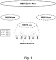
- a possible deployment option of MBMS service using a pre-defined area is as shown in Fig. 1 .
- MBSFN service area is the area where all eNBs can be synchronized to provide MBSFN transmission and could contain multiple MBSFN areas.
- an (e)MBMS service area can include multiple MBSFN areas, but also single eNBs that are not part of any MBSFN area. From a UE perspective, all transmissions from a single MBSFN area eNBs are seen as a single transmission.
- the cells within an MBSFN area will advertise its availability and UEs can consider a subset of MBSFN areas that are configured. As shown in the figure, there could be reserved cells within MBSFN area which does not have any MBSFN transmissions and can use the resource allocated for MBSFN in neighboring cells for other services.
- these reserved cells transmit the (e)MBMS data in different radio resources than the MBSFN area. But the maximum transmit power that can be allocated for such resources are limited so as to not cause interference to MBSFN cells.
- MBMS reception is possible for UEs in RRC_CONNECTED or RRC_IDLE states. Whenever receiving MBMS services, a user shall be notified of an incoming call, and can make outgoing calls (as specified in 3GPP TS 36.300, "E-UTRA and E-UTRAN: Overall description; Stage 2," v 11.5.0, March 2013 , briefly denoted [2] hereinafter).
- MBSFN service area and (e)MBMS service area have different meaning, but in the context of the present invention these terms may be used in an interchangeable manner, i.e. expressing in general an area where the UE receives (e)MBMS data via (e)MBMS bearer service.
- An (e)MBMS bearer service is identified by an IP multicast address, an APN network identifier and also by a TMGI (Temporary Mobile Group Identity) inside one PLMN.
- the UE can use the TMGI as ID for the (e)MBMS bearer service over certain access technology.
- the UTRAN MBMS bearer service and the E-UTRAN eMBMS bearer service would have 2 different TMGIs.
- Multi-Cell/Multicast Coordination Entity could be a functional entity which could be either stand-alone node or a part of another network node (e.g. eNB as shown in Fig. 3 (b) ).
- the MCE takes care of admission control, counting results of MBMS services, and resumption or suspension of MBMS sessions depending in the counting results.
- the M3 reference point is specified for the control plane between MME and E-UTRAN, assuming that the MCE is a part of the E-UTRAN.
- the details of the (e)MBMS reference points and related functional entities can be found in the above mentioned standard document [2].
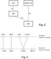
- Fig. 3 Two possible deployment alternatives that are considered in [2] are shown in Fig. 3 , with additional consideration of an X2 interface between eNBs for the present invention.
- the services which are envisioned to be provisioned using MBMS are streaming of audio and video, updates of smartphone applications, etc. (as outlined in [1]). It is also considered that the regions where these services are to be delivered will be pre-planned and service continuity over the MBSFN area is enabled by using careful prior planning of the network.
- the service continuity is enabled as the MBMS service data is delivered in the same radio resources in the cells participating in the MBSFN area. In the boundary area of two cells, the UE can combine the signals coming from the two cells, and therefore, the probability of correct reception is increased.
- MCH Multicast Channel
- the MBMS control information is conveyed using MCCH logical channel and user data using MTCH logical channel which can be used for multiple MBMS services within an MBSFN area.
- MCCH logical channel and user data using MTCH logical channel which can be used for multiple MBMS services within an MBSFN area.
- RAN Radio Access Network
- P2M bearer uses the mechanisms specified in 3GPP for transmission of data from BM-SC to UE.
- the reason for this is that current MBMS applications are mainly streaming applications and short interruption perceived by the user is not critical.
- GCSE_LTE Group Communication System Enablers for LTE
- radio resource efficiency via MBMS transmission and service continuity are key features.
- Radio resource efficiency is “to avoid duplicated/unnecessary radio resources allocated for different group members in a certain cell” and “to minimize impact on signaling plane for the network”. If many UEs are located in the same area, then MBMS is considered as one of the potential technologies to achieve this resource efficiency when transmitting Group Communication (GC) service data (see, for reference S2-131509, "Architecture & functional requirements for GCSE_LTE,” Qualcomm Incorporated). In cells where there are only few UEs, the network may decide to distribute the GC service data in unicast way.
- GC Group Communication
- WO 2008/052382 A1 discloses a method in connection with a multimedia service transmission intended for multiple receivers, i.e. MBMS, wherein the multimedia service transmission intended for multiple receivers is sent from a radio transmitter to at least one receiver.
- the at least one receiver, UE does performance related measurements and maintains counters that are related to the user experience and the radio transmission reception of MBMS transmission.
- the UE reports these results to a management entity, for instance in the core network, or to the base station.
- US 2007/0011503 A1 describes the combined use of multicast communication and unicast communication in a communication terminal that selects the optimal reception system. Specifically, the terminal performs multicast/broadcast service related radio measurements and a decision on actions to be performed by the base station and/or by the terminal for preserving reliable transmission/reception of multicast/broadcast service related data to/by the terminal is taken based on the results of the multicast/broadcast service related radio measurements, deciding on multicast delivery if the received signal strength indicator is larger than a threshold, and deciding on unicast delivery otherwise.
- the aforementioned object is accomplished by a method comprising the features of claim 1.
- a mobility management entity, MME of said radio access network, upon being informed by said mobile terminal of a successful start of MBMS data reception by said mobile terminal, signals an update of said mobile terminal's context including information of the mobile terminal's currently received MBMS bearer services to said base station, wherein said base station, based on the update of said mobile terminal's context signaled from said MME, determines whether to configure said mobile terminal to send MBMS related radio measurement reports to said base station.
- a base station comprising the features of claim 12.
- such a base station is characterized in that said base station is configured to receive from a mobility management entity, MME, of said radio access network, upon said MME being informed by said mobile terminal of a successful start of MBMS data reception by said mobile terminal, an update of said mobile terminal's context including information of the mobile terminal's currently received MBMS bearer services, wherein said base station is configured to determine, based on the update of said mobile terminal's context signaled from said MME, whether to configure said mobile terminal to send MBMS related radio measurement reports to said base station.
- MME mobility management entity
- such a system is characterized in that the system comprises a mobility management entity, MME, wherein said MME is configured, upon being informed by said mobile terminal of a successful start of MBMS data reception by said mobile terminal, to signal an update of said mobile terminal's context including information of the mobile terminal's currently received MBMS bearer services to said base station, and wherein said base station is configured to determine, based on the update of said mobile terminal's context signaled from said MME, whether to configure said mobile terminal to send MBMS related radio measurement reports to said base station.
- MME mobility management entity
- the main idea of the present invention is based on the UE-assisted reporting of MBMS-related radio quality conditions (MBMS-related radio measurements) to the radio network node (eNB), and the radio network (eNB) takes a decision how to provide the reliable transmission of the MBMS data to the UE.
- the UE's current/existing radio measurements (used for the mobility procedure) may be extended to additionally include information about the MBMS radio signal quality.
- the eNB may decide based on MBMS service topology (e.g. if the MBMS service, both MBSFN or non-MBSFN, is configured in the neighboring cells or if unicast transmission conditions are possible) which actions to perform in order to guarantee the service continuity of the MBMS service reception in the UE.
- the MBMS-related information (MRB reporting) in the measurement reports from UE to eNB can be e.g. MRB signal strength (similar to the signal strength of pilot signal as reported currently in measurement report), or decoding error of received MRB data, or block error rate of received MRB data and other possible physical layer, MAC layer or RLC layer parameters.
- MRB signal strength similar to the signal strength of pilot signal as reported currently in measurement report
- decoding error of received MRB data or block error rate of received MRB data and other possible physical layer, MAC layer or RLC layer parameters.
- MBSFN carrier symbol there is an MBSFN carrier symbol within the transmission frame as described in [2] (3GPP TS 36.300, section 5.1.4). This MBSFN carrier symbol can be used as referenced signal to generate the MBMS-related information in the UE's measurement reports.
- MBMS multimedia service
- MRB Multicast/Broadcast-Radio
- MRB multicast radio bearer
- the present invention describes several flavors of the solution for the problem of providing service continuity.
- solutions according to embodiments of the present invention provide the benefits of 1) service continuity, i.e. no data flow interruption is perceived by the application layer receiving the MBMS data and 2) the switch from multicast to unicast delivery only if needed (i.e. not too early when the switch can be avoided or not too late when the connection is disrupted).
- two base stations - denoted eNB1 and eNB2 - are part of the same MBMS service bearer.
- the eNBs transmit the MBMS data over the MRB with the same signal strength and on the same frequency (sub-carrier) for the whole cell, it may happen that the eNB transmit the MRB data with less power strength than the possible maximum power strength used for unicast DRBs in order to keep the interference to neighbor sub-carriers low.
- MRB MBMS
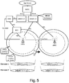
- unicast transmissions Another reason for different coverage areas of MBMS (MRB) transmissions on the one hand and unicast transmissions on the other hand is the fact that the frequency sub-carriers configured for MRB transmission (which cannot be chosen flexibly due to, e.g., MBSFN area configuration) can have worse propagation conditions compared to the dynamic use of sub-carriers for unicast transmission. Due to this fact, the cell coverage (or cell border) for MRB transmission may be smaller than the cell coverage (cell border) for unicast DRBs. In Fig. 5 , the MRB transmission cell border is shown by interrupted lines, whereas the unicast transmission cell border is shown with solid lines. In such situation, when a mobile terminal - denoted UE in Fig.
- the UE may not be able to correctly receive MRB transmission while the unicast DRB data can be still received correctly.
- the consequence is that the UE is not able to receive the MBMS data in the cell border, and therefore, the service continuity for the applications receiving the MBMS data is not provided.
- the UE when a UE is moving to the edge of the eNB1 cell or the eNB2 cell, and the UE is receiving the MBMS bearer service, the UE would lose the MBMS reception in eNB1 cell and in eNB2 cell, even before reaching the cell borders for handover conditions. For the time duration when the UE is located between the borders of the 'MBMS cell reception borders' of eNB1 and eNB2 cells, the UE would not have MBMS reception.
- the MBMS service area (MBMS/MRB coverage) within the cell is smaller than cell coverage for unicast transmissions, and therefore, the UE would lose MBMS reception before reaching cell edge as defined for the handover conditions.
- MBMS service continuity is described in document [2] (TS 36.300, section 15.4).
- the specification describes that service continuity is provided when the UE moves within the same MBSFN area.
- the UE in IDLE state can change the prioritization of frequencies in order to keep the reception of the MBMS service in the MBSFN area.
- a UE in CONNECTED state may indicate its preference in receiving MBMS service compared to unicast reception and the eNB can decide whether and how to map/schedule the frequencies for unicast transmission in order to keep the MBMS service reception.
- the UE can request the unicast transmission of the received service from the Application Server upon detection of service disruption via MBMS reception.
- the UE's application layer can detect the loss of data packets or frequent request for packet retransmission. This detection can be used as trigger for the UE's application to request via application level signaling to the Application Server (e.g. Public Safety Application Server or any other server which generates the data sent over MBMS bearer service in the 3GPP network) the transmission of the service data via unicast delivery.
- the Application Server e.g. Public Safety Application Server or any other server which generates the data sent over MBMS bearer service in the 3GPP network
- this is an application layer based detection of service disruption and according application layer initiated signaling to application server to request appropriate actions (e.g. unicast transmission of data) to preserve service continuity.
- the 3GPP layers access stratum or non-access stratum implementations
- the 3GPP layers detect that the (e)MBMS data cannot be received correctly, e.g. cannot be demodulated or decoded correctly at the 3GPP's physical, MAC or PDCP layers after reception.
- the 3GPP layers indicate to the Application layer the loss of service, so that the Application layer can take the needed actions.
- the Application layer requests from the GC-AS (via application layer signaling) unicast transmission of the GC session data.
- the Application initiates the application level signaling.
- One disadvantage is that the time duration between the detection of MBMS data loss and reestablishing of the service data reception in a unicast delivery manner (using existing or a new established EPS bearer) depends on the UE implementation, network and service provider conditions. This time duration may be considerable, and thus, obviously, no service continuity is provided. Therefore, reliable solutions are needed to assure service continuity.
- Fig. 6 this figure illustrates a scenario together with the corresponding signaling flow in accordance with a particularly preferred embodiment of the present invention.
- configuration procedure(s) for the mobile terminal (UE), RAN and core network (C-plane, e.g. MME) are carried out in the beginning in order to setup the conditions which allow to perform the solution.
- the configuration procedures include steps (1), (2) and (3), as shown in Fig. 6 .
- the main part of the illustrated embodiment is based on the entity located in the RAN, preferably it is an eNB, denoted eNB in Fig. 6 , which takes care about the service continuity.
- the eNB determines that MBMS service is about to be interrupted due to bad radio conditions. Consequently, the eNB determines what actions to perform in order to guarantee the service continuity of the MBMS data.
- the enhanced eNB functionality is shown in steps (5) and (6).
- the UE needs to be extended with functionality to perform procedures conformant to the action(s) decided by the eNB for service continuity.
- the UE exchanges capabilities about support of (e)MBMS bearer service continuity.
- This capability exchange may happen either (a) during an Attach procedure, e.g. the UE includes the capability as part of the Attach request message, or (b) when the UE starts receiving (e)MBMS bearer services as an explicit NAS signaling exchange between UE and MME or RRC signaling between UE and serving eNB.
- step (1) the UE activates the reception of MBMS bearer service, which can be the GC data/media via a multicast delivery from the content provider (GC-AS) via an (e)MBMS bearer service.
- This step (1) includes signaling between UE, MME, and MBMS-related entities in the core network, e.g. MBMS gateway (MBMS GW) and/or BM-SC, as the purpose is to join to the already established MBMS bearer service.
- MBMS gateway MBMS gateway
- BM-SC BM-SC
- step (2) after the UE starts receiving (e)MBMS bearer service(s), the UE updates either the MME or the eNB or both about the current actively received eMBMS bearer service(s).
- the UE, or the MME, or both can indicate to eNB the TMGI(s) corresponding to the (e)MBMS bearer service(s).
- the indication can include the type of MBMS service, i.e. whether service continuity for this MBMS bearer (for the given UE or general for all UEs receiving this MBMS bearer) is needed or not. Further, the indication can provide information about the priority of the MBMS service compared to unicast DRB reception.
- step (2) two different embodiments - denoted by A and B in Fig. 6 - are envisioned on how information related to the UE's currently received MBMS service can be updated to the eNB or MME. These two embodiments are described as follows:
- step (2.A.1) the UE may indicate to the MME the successful joining to the MBMS bearer services (i.e. after successful reception of the MBMS data). This step can be performed optionally if the UE is configured to perform it. The configuration of the UE can be performed e.g. during step (0) described above or during any other NAS procedures as attach or TAU procedures. If the MME can become aware about the successful joining of the MBMS bearer service, then step (2.A.1) may be omitted and the MME can proceed with next step (2.A.2).
- step (2.A.2) after the MME is informed about the successful start of MBMS data reception by the UE (or joining the MBMS bearer service), MME updates its own UE's context, and further, performs UE's context update in the current eNB.
- This update to the eNB can include MBMS bearer service ID (e.g. TMGI), specific UE priorities (ARP) for the MBMS bearer service compared to other UE's unicast bearer(s) and other parameters.
- TMGI MBMS bearer service ID
- ARP specific UE priorities
- the UE can indicate to the eNB the activated reception of the MBMS bearer service (i.e. joining the MBMS bearer or start of successful reception of MBMS data).
- exemplary an RRC signaling can be used to exchange this indication between UE and eNB.
- the indication can include the MBMS bearer service ID (e.g. TMGI), specific UE priorities (ARP) for the MBMS bearer service compared to other UE's unicast bearer(s) and other parameters.
- step (3.1) after the eNB has been updated about the activated UE's MBMS bearer reception, the eNB determines whether the UE should be configured to include in its radio measurement reports also information about the quality of the MRB reception (or MBMS radio signal quality). It should be noted that the measurement reports are currently used as tool for the RAN to know whether handover procedure should be initiated, or to estimate the signal power for radio transmission. If the UE has activated multiple MBMS bearers, then the eNB should determine whether to activate the measurement reporting per MBMS bearer. With other words, for one MBMS bearer the reporting may be activated, but for other one it may not be activated. The eNB can use the priority or other criteria (e.g.
- the UE can indicate during step (2.A.1) or (2.B.1) whether service continuity for a particular MBMS/MRB bearer is needed.
- the eNB can determine whether the current UE measurement reporting should be changed, e.g. from “event-based” reporting to “periodic” reporting, or vice-versa from “periodic” to “event-based” reporting. Further, it is possible to configure the MBMS measurement reporting independently from the measurement reporting configured for handover procedure.
- the eNB may have knowledge about the MBMS service transmission in the neighbor cells, e.g. in which radio resources (frequencies) the MBMS/MRB is transmitted. If such information is available, the eNB can configure the UE with those MBMS resources in the neighbor cells, so that the UE can perform also MRB measurements for the neighbor cells similar to the (unicast) radio measurements for mobility.
- step (3.2) the eNB instructs the UE about the radio measurements including the MRB reporting.
- the MRB reporting can be configured for one or multiple of the currently received MBMS services. Further the MRB reporting can be performed also for neighbor cells.
- This instruction can be performed as an existing or new RRC signaling message, e.g. as reply to step (2.B.1), if option B from step (2) has been used.
- the eNB can use RRCConnectionReconfiguration message with extensions to the mobilityControlInformation or a new information e.g. called MBMSControlInformation.
- the UE can be configured to stay in CONNECTED state due to the MRB reporting.
- the UE may be configured with long DRX in order to save uplink resources. Event-based MRB reporting is also possible, as will be described in detail below in connection with Fig. 8 .
- the UE sends enhanced radio measurement reports including MRB/MBMS-related radio signal reports to the eNB.
- the UE needs to re-configure its radio interface to start gathering MRB radio information similar to the unicast radio information measurements performed for the mobility/handover procedure.
- This MRB/MBMS reporting can be a part of the current UE's measurement reports to the eNB, or it can be a separate reporting.
- the measurements reports are sent over RRC signaling (RRC "MEASUREMENT REPORT" message from UE to eNB), so that it is preferable to extend this existing RRC signaling from UE to eNB to include MRB/MBMS reporting. Further details about the UE reporting will be described below in connection with Fig. 8 .
- step (5.1) the eNB determines the UE's reception quality of the MRB bearer (MBMS data) based on the measurement reports received in step (4). If the eNB determines that data loss of MRB connectivity is possible due to bad radio conditions, the eNB takes measures to preserve the service continuity for this MBMS bearer. It should be noted that for one MBMS bearer the radio conditions may be bad, whereas for other MBMS bearer or unicast bearer(s) received by the same UE the radio conditions can be still good. The eNB determines whether to provide service continuity for the given MBMS bearer with bad radio conditions based on the MBMS bearer type (i.e. importance, QoS parameters or kind of service) configuration during step (2), including the options A or B described above, and step (3.1).
- the MBMS bearer type i.e. importance, QoS parameters or kind of service
- the eNB shall determine which actions can be performed in order to assure the service continuity. This is generally shown as step (5.2) in Fig. 6 .
- the eNB takes into consideration the MBMS transmission in the neighbor cell(s) according to the measurement report from step (4), but also the unicast bearer radio conditions.
- the eNB can take one or more of the following optional actions:
- the eNB should decide according to the priority of MBMS and unicast services, i.e. if MBMS service(s) has higher priority, then the eNB should decide to perform handover to the neighbor cell, although the normal (unicast, non-MBMS) measurements do not indicate handover.
- the eNB can determine to apply option A from above, i.e. temporary transmission of the MBMS data over unicast DRB bearer, if the normal (non-MBMS, unicast) mobility measurements indicate that handover procedure is not required and/or the unicast transmission has higher priority than the MRB transmission.
- Option C This option, shown in step (5.C.2), is applicable in scenarios where the UE is close to the cell border to another target cell, which is not part of the MBMS service. With other words, the UE is going to leave the MBMS service area soon. As the MBMS data cannot be received in the neighbor cell anyway, the eNB may decide to trigger the UE to send an application level request for unicast delivery. Alternatively, the eNB may simply indicate to the UE that MBMS service continuity cannot be provided by the RAN. This is shown in detail in Fig. 9 .
- Option D This option, shown in step (5.D.2), involves the MME in the decision process for the "action" to be taken for service continuity. For example, after the eNB determines the bad radio conditions for MBMS/MRB transmission for the given UE in step (5.1), the eNB indicates to the MME that the MBMS/MRB reception for the UE is going to be interrupted (or lost). Then the MME can take actions to avoid this interruption.
- One possible action would be that the MME informs the UE (e.g. via NAS signaling) about the MBMS/MRB reception loss, so that the UE's NAS layer can inform the application layer to take application layer measures to keep the service continuity.
- the indication from MME to UE can use an existing or a new NAS message and can contain the TMGI of the MBMS service. It should be noted that the indication from MME to UE is not shown in Fig. 6 . Further, it should be noted that the signaling between eNB and MME involves the M2 and M3 interfaces and possible the MCE entity. This eNB-MME signaling needs to be extended to allow the indication of the new determination of bad MBMS/MRB radio conditions for a given UE.
- Option D can be applied as alternative for signaling exchange from eNB -> MME - > UE to all options A, B, C or other possible options.
- the MME initiates or allows a bearer modification procedure for the DRB only (not the whole EPS bearer) as described in step (5.A.2) above. This can be signaled from MME to eNB, so that the eNB can proceed further with step (6).
- step (6) the eNB indicates the determined action to the UE.
- This step can be done for all options for which the "action" for service continuity is decided in the eNB, as shown in steps (5.A.2), (5.D.2) and (5.C.2).
- the indication from the eNB to the UE can be included in an existing or a new RRC message. The content of the indication depends on the determined action in step (5.2). If eNB determines to apply option B from step (5.2), then no indication is needed.
- the eNB indicates to the UE that the MBMS service will be temporarily delivered over a particular unicast DRB.
- the indication can contain: 1) the MBMS service ID (e.g. TMGI, which the eNB stores in the UE's context as described in steps (1), (2) or (3)); and/or 2) the unicast bearer ID (DRB ID or EPS bearer ID), and/or 3) modified RRC connection parameters (e.g. DRX parameters, Inactivity timer); etc.
- the indication can contain information to the UE that the MBMS data is going to be transmitted over DRB, so that the UE does not need to perform any MBMS-related signaling/actions due to bad MBMS/MRB reception. With other words the UE may temporarily ignore the reception of the MBMS data over MRB.
- step (5.2) If eNB determined to apply option C from step (5.2), further details about step (6) are described below in connection with Fig. 9 .
- step (7) the UE takes the actions according to the indication in step (6).
- step (7) further details about step (7) are described below in connection with Fig. 7 .
- option C further details about step (7) are described below in connection with Fig. 9 .
- the UE receives the indication from the eNB e.g. via RRC signaling, however the actions to be performed by the UE are on higher layers. Therefore, it is required that the UE implements ability (e.g. internal means or internal interfaces) in order to convey the information obtained in lower layer to the corresponding upper layer or software module.
- ability e.g. internal means or internal interfaces
- the UE needs first to implement means to understand this information and to derive the required action, to derive the concerned application, and also means to internally convey this information to the concerned application.
- the UE implements a kind of dispatcher software/layer/module, so that e.g. the RRC layer sends the indication to the dispatcher software/layer/module, which in turn determines the impacted/concerned application.
- step (5.2) which is not depicted in Fig. 6
- the eNB can increase the MRB signal strength according to the received MRB measurement report, so that the MBMS data is received with higher quality at the UE.
- the eNB can modify the modulation and coding scheme (MCS) to increase the robustness of the MRB data transmission.
- MCS modulation and coding scheme
- the problem may arise that the throughput may not be sufficient.
- the eNB may decide to schedule the MRB transmission more frequently.
- possible limitations of the MRB scheduling might occur.
- the above solution option of increasing the signal strength would be reasonable as this would allow the UE to combine the MBMS/MRB signals from both cells and to achieve correct reception.
- the eNB processes the UE's measurement reports as part of the mobility procedure, i.e. to decide whether a handover procedure to neighbor cell should be performed.
- the MBMS/MRB-related information in the extended measurement reports is processed by the eNB for providing service continuity (i.e. not for mobility procedure).
- the MBMS/MRB-related information in the extended measurement reports is used for a new "MBMS service continuity" procedure in the eNB.
- Fig.7 this figure shows further details about option A of the possible actions determined by the eNB, i.e. step (5.A.2) as described above in connection with the embodiment of Fig. 6 .
- Fig. 7 shows the MBMS data flow (in the downlink).
- the MBMS-GW sends the data to the eNB via M1 reference point.
- the eNB maps the MBMS data over a MRB and all UEs that have activated the MBMS bearer reception would receive the MBMS data.
- UE_A one of the UEs
- the eNB determines to apply unicast transmission of the MBMS data to the UE_A in order to keep the MBMS service continuity.
- the eNB maps the MBMS data on a unicast DRB.
- the UE_A can have one or more unicast DRB(s) established simultaneously.
- the eNB should decide which DRB to use based on the MRB's QoS parameters and the DRB's QoS parameters.
- mapping the MBMS data on GBR DRB may be not a good solution because the service already transmitted over the GBR DRB may be impacted. Therefore, it is advisable to map the MBMS data on non-GBR bearer having the Allocation and retention priority (ARP) value which is same or possibly similar to the MRB's ARP.
- the eNB copies/multiplies the MBMS data that is sent over the MRB to the unicast DRB.
- the eNB can temporarily change or upgrade the DRB's QoS parameters (QCI, ARP, etc.) to be the same as the MRB's QoS parameters as long as there is no overload or congestion scenario.
- Such update of the QoS parameters is done locally at the eNB and can be optionally communicated to the UE.
- the eNB can decide to perform this action based on the MBMS data service importance or based on the UE's preference/importance signaled during steps (1) or (2) of Fig. 6 . If overload or congestion scenario happens, the eNB should restore the original DRB's QoS parameters. Whether to restore the original QoS parameters depends on the configuration in the eNB received from UE or MBMS bearer establishment during steps (1) or (2) of Fig. 6 .
- the determining in the eNB how to transmit the MBMS data to the UE can be performed internally in the eNB.
- eNB does not perform explicit signaling/indication to the UE, but instead internally treats the MBMS packets differently from the data packets coming from the S/P-GW over S1-U interface correspondingly to the DRB selected to MBMS transmission. For example, if MBMS reception has higher priority than the unicast data reception, the eNB can schedule the MBMS data packets with higher priority transmission (similar or same to the QCI used for the original MRB transmission) than the unicast data over the same DRB.
- the UE is not aware about the different treatment of MBMS and unicast packets in the eNB. This differentiated treatment is possible for the downlink transmission; however, it is not possible for the uplink transmission.
- the MBMS data For the transmission of the MBMS data over the DRB, the MBMS data needs to be processed in the eNB according to the processing of the unicast data packets.
- the eNB needs to perform the PDCP (Packet Data Convergence Protocol) layer, RLC (radio link control) layer and MAC (medium access control) layer processing.
- PDCP Packet Data Convergence Protocol
- RLC radio link control
- MAC medium access control
- the UE is able to distinguish the MBMS data from the unicast data e.g. based on the destination IP address of the IP packets.
- the MBMS data packets have multicast IP address, so that the UE is able to forward the MBMS to the correct application even though the packets were transmitted over the unicast DRB.
- the UE's Application which receives the MBMS data, would not initiate any application-level signaling or actions to change the reception mode from the App server.
- the UE ignores the reception of the MBMS data over MRB for the time the UE receives the MBMS data over DRB.
- Having the different scheduling treatment of MBMS and non-MBMS data i.e. to treat the data as from different radio bearers
- same radio bearer would allow to fulfill the QoS requirements (e.g. different QCI) of the original MRB and unicast transmissions, whereas the optimal usage of radio resources is guaranteed.
- the eNB is extended to apply sub-division of the packets belonging to the same radio bearer (e.g. can be compared like having one radio bearer with two sub-bearers).
- Fig. 8 is a flow chart illustrating both for the UE and the eNB functionalities/procedures for steps (4), (5.1) and (5.A.2), i.e. for Option A from Fig. 6 .
- the upper part of Fig. 8 shows the UE part where the UE reports the radio measurements to the eNB depending on the configuration. If event-based reporting is configured in the UE, then the event can be related to the MBMS&MRB reception only, i.e. independent from the unicast radio measurement for the mobility procedure. In such case the measurement report contains only the MBMS/MRB-related measurements.
- the "event” for the event-based reporting for the state-of-the-art mobility procedure is defined by thresholds of the signal strength of the current and neighbor cells.
- the “event” can be the absolute drop of the signal strength/quality of the MRB signal under a pre-defined threshold.
- the UE can apply the state-of-the-art "events” by comparing the MRB signal strength of the current and neighbor cells.
- the eNB determines whether the MBMS/MRB signal quality is poor. If this is the case, the eNB determines which action to perform as described in step (5.1) from of Fig. 6 .
- Fig. 8 shows only the options A, B and C from step (5.2) in Fig. 6 (i.e. omitting option D). As will be appreciated by those skilled in the art, further options for actions (not shown in Fig. 8 ) are possible.
- This determination/decision can be influenced by configurations or capabilities during steps (0), (1) or (2). For example it may depend on UE's capabilities, MME's capabilities or eNB's capabilities. Further, as described in the different options in step (5.2) of Fig. 6 , the eNB decision can depend on the MBMS/MRB and non-MBMS (normal unicast) measurement reports.
- Option A has been described already in more detail in connection with Fig. 7 .
- Fig. 8 depicts the two possible branches of Option A depending on whether eNB cell is in congestion or limited radio resources. If there are enough available radio resources, then eNB can decide, if needed, to locally upgrade the radio DRB in order to adapt the QoS parameters to the MRB's QoS parameters. Otherwise the eNB maps and transmits the MBMS data over the unicast DRB without modification of the DRB bearer.
- the UE Since the transmission (or reception, respectively) of the MBMS data over a unicast DRB is meant to be temporal, the UE does not perform MBMS-related signaling with the BM-SC for deregistration, leave, change or other actions for the MBMS session control.
- the UE continues to perform the MBMS/MRB measurements (additionally to the usual radio measurements for mobility procedures), and thus, the UE continues to send measurement reports (event-based or periodic) to the eNB.
- the eNB evaluates the measurement reports and determines how to proceed in order to guarantee service continuity. In accordance with embodiments of the present invention, in this case the eNB may decide one of the following actions:
- Fig. 9 is a signaling diagram that illustrates some more details related to step (5.2) of option C from Fig. 6 , i.e. Fig. 9 is related to a scenario where service continuity is achieved based on application level signaling.
- the detailed explanation of Fig. 9 is given as follows: Steps (0-4), are similar to the ones explained in connection with Fig. 6 .
- eNodeB based on measurement reports from the UE determines that (a) UE is having bad radio conditions, (b) determines whether higher level actions are required or whether the reports indicate only a short period of disruption. If the eNB determines that longer-term actions are needed, e.g. the UE is approaching a neighbor cell where the MBMS service is not configured or the UE is a low mobility device which reports bad MRB conditions for long time, the eNB can decide to indicated higher level action to the UE. It should be noted that "higher level action” means that the poor MRB reception cannot be recovered by radio layer 1 or layer 2 procedures, and therefore, e.g. actions from the application in the UE are needed.
- step (6) once eNB determines that actions are required above the radio layers, e.g. to request for unicast delivery from the communication peer, eNB sends explicit indication to the UE.
- This indication from eNB to UE could be in the form of RRC signaling.
- event-based measurement reports are configured for MBMS/MRB reference signal reporting, events should be configured in such a manner that UE reports poor radio conditions of the MBMS/MRB reference signal appropriately.
- the eNB takes decision for high-level action, if the eNB cannot guarantee MBMS service continuity on the radio layers. This can happen if the eNB is configured with this solution, or the eNB cannot apply other solutions described herein as embodiments of the present invention (e.g. mapping of MBMS-data over unicast DRB, increase signal strength for MRB transmission, etc.).
- the eNB can inform the MME, so that the MME can inform the UE, e.g. via NAS signaling.
- the indication from the MME to UE includes MBMS service ID and appropriate action type, e.g. no longer MRB radio transmission possible, or higher-layer actions needed for service continuity.
- the UE needs to implement internal functionality, similar to the functionality described in connection with step (7) of Fig. 6 , where the UE is capable to derive/understand the action as indicated by the eNB, and further is able to convey the indication to the impacted/concerned application or internal module/layer.
- step (7.1) once UE receives the indication from the eNB (or MME) about higher-layer actions needed, the UE first determines internally which application is impacted. This can happen e.g. in the NAS layer. With other words, the received indication from eNB in the RRC layer is forwarded to the NAS layer. Then the UE (NAS layer) forwards this indication to the application layer which receives the particular MBMS service (according to the MBMS service ID, TMGI). The UE's application then generates an application layer message to request unicast service delivery by sending a relevant indication to the application server. This application layer message is sent over an existing (or new) EPS bearer to the application server.
- step (7.2) once the App Server receives this request to send data in unicast, it starts sending data over unicast bearer to the UE. This may result in the establishment of new EPS bearer in the 3GPP network.
- step (8) UE starts receiving data via unicast bearer over the serving eNB. If the UE would move out of the coverage footprint of the MBMS reference signal, the UE would keep the service/App data receptions, as the unicast transmission is more flexible (in terms of resource utilization) than the multicast transmission.
- the UE may inform the eNB and/or MME that the UE no longer receive the MBMS service.
- the UE deregisters with the eNB and/or with the MME regarding the MBMS service reception.
- the UE may also deregister for the given MBMS service with the BM-SC.
- the embodiments of the invention described above are based on the concept where the RAN (eNB) determines about switch from multicast to unicast delivery.
- the RAN eNB
- an embodiment is described which is based on an alternative concept where the decision for the service continuity, i.e. for the switch from multicast to unicast delivery, is taken in the UE.
- the solutions how the UE can determine the bad radio conditions for MBMS reception can be separated in two main categories: 1) solutions at the 3GPP radio layers (e.g. Physical or MAC layer) or 2) solutions at a higher layer above the 3GPP layers (Application layer or TCP layer).
- the UE can determine the poor radio conditions of the MBMS reception based on the packet losses at the higher layer above the 3GPP layers (Application layer or TCP layer).
- the layers above the 3GPP layers determine the need to initiate the switch from multicast to unicast delivery.
- the possible mechanisms to determine the need for App layer actions for service continuity are e.g. 1) the detection of missing packet, or 2) the triggering of retransmission mechanism in the layers above the 3GPP layers.
- the application layer may have a retransmission mechanism for requesting lost packets. If this retransmission mechanism is triggered for a configurable number of times, then the UE can determine that the radio conditions for MBMS reception are poor and the UE can decide to switch to unicast delivery.
- the data (streaming) codec used between the BM-SC and UE can also determine that retransmissions are needed.
- a similar approach is described in 3GPP TS 26.346 in section F.2 for the switching from MBMS to PSS (Packet-switched Streaming Service), however, this approach detects the need for switch after packet losses have already occurred.
- this is denoted as "MBMS layer” (or protocol stack generally responsible for performing the MBMS-relevant actions). For example, if the "MBMS layer" would request transmission of the MBMS data from the BM-SC, then the MBMS layer instead of requesting the retransmission can indicate the App layer to initiate request for unicast delivery. Based on this determination for retransmission in the MBMS layer, the UE can determine about the poor radio conditions, and consequently, the UE can request the application layer to take actions to switch from multicast to unicast delivery.
- Another embodiment for determining the switching from multicast to unicast delivery at higher layer above the 3GPP layers is to use the sequence number of the IP packets at the transport layer, e.g. TCP or UDP/RTP segments. If the transport layer (or other layer having sequence number of the received packets) determines that a segment/packet is missing, then the transport layer can indicate to the application layer (to which the packets are destined) that there are missing packets and actions from the application layer are needed. In such case, the application layer would request unicast delivery from the application server.
- the transport layer e.g. TCP or UDP/RTP segments.
- the detection for switch to unicast delivery at the higher layer above the 3GPP layers may have the following drawback.
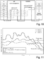
- An LTE protocol stack and possible interaction with GCSE is as shown in Fig. 10 .
- PHY physical layer
- having an application layer trigger for service continuity would essentially mean that there would be significant amount of delay between packet being sent by the GC-AS and the same reaching the group communication application in the UE.
- the detection of the possible loss of data via multicast transmission, and also possible service disruption, in the 3GPP radio layers has the advantage of avoiding packet losses and less delay.
- the UE detects poor radio condition at the 3GPP radio layer(s)
- an indication is sent internally in the UE to the application which receives the MBMS data.
- the application can undertake the needed actions to request from the transmitting server a unicast delivery of the group session data.
- the UE In order for the UE to determine the poor radio conditions at the 3GPP radio layers, the UE needs to be configured with the threshold(s) for the MBMS radio signal strength.
- the configuration of the thresholds in the UE can be performed e.g. in one of the following manners (the list is not exhaustive):
- the disadvantage of UE internally determined thresholds is that the UE may not have knowledge about the environment (e.g. urban, rural) and whether the neighbor cells are part of the same MBSFN area. Therefore, in connection with Fig. 12 the configuration of the thresholds via the RAN node (eNB) will be described.
- the eNB can determine the signal thresholds in a similar way as described in the embodiment of Fig. 11 , but additionally considering some of the following conditions: the MBMS bearer coverage (e.g. based on the drive test from other UEs), MCSs, radio environment (e.g. urban, rural), type of media, the configuration of the MBMS bearer in the neighbor cells and or whether the neighbor cells are part of the same MBSFN area, etc.
- the following embodiment describes a mechanism for MBMS reference signal measurement configuration and thresholds in the UE by the eNB.
- This mechanism is basically derived from the embodiment of the invention described in connection with Fig. 6 enabling service continuity based on eNB involvement.
- the main concept of this embodiment is that the UE determines and initiates actions (e.g. on the layers above the 3GPP layers, like application layer) to maintain the service continuity based on radio configurations in the UE performed from a RAN node, e.g. eNB.
- the UE may initiate the actions for service continuity when certain thresholds of the MBMS reference signal measurement are exceeded (e.g. thresholds related to packet, bit and/or block error rates) or under-run (e.g.
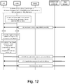
- Step (0) shown in Fig. 12 to (3.1) is identical or similar to steps (0) to (3.1) described in connection with Fig. 6 .
- the detailed explanation of Fig. 12 is as follows: Step (0) is similar to the steps (0)-(3.1) from Fig. 6 , whereby a UE subscribed to group communication services, either in RRC_Idle or RRC_Connected mode enters the coverage area of a cell or eNB transmitting group communication services using eMBMS.
- step (1) eNB sends MBMS reference signal threshold configurations to the UE, either (a) using system information blocks which could be read by the UEs in idle and connected state or (b) using RRC signaling by the eNB.
- the thresholds could depend on the radio configuration used in the cell for eMBMS transmissions, such as modulation and coding scheme, the channel conditions in the cell, etc.
- the UE also starts receiving group communications data using multicast transmissions from the application server. It should be noted that in step (1) in Fig. 12 , the order of the reception of multicast service on the one hand and the eNB configuration of MRB measurements on the other hand is arbitrary.
- the eNB is aware about the UE's activated MBMS services (GC services sent over MBMS bearer) and if the UE is in connected state, the eNB can use dedicated RRC signaling to the UE in order to configure the UE with MBMS reference signal thresholds. For this purpose, existing RRC signaling messages or newly defined RRC signaling messages can be used. The use of the configured MBMS signal thresholds is described in step (2).
- step (2) when the MBMS reference signal quality (or any signal from which MBMS reception quality can be estimated) goes below a threshold configured in step (1), the UE determines in sub-step (a) that the UE has reached a region where the probability of losing multicast signal reception is high, due to bad MRB radio conditions or any other factors due to which multicast reception could be lost.
- sub-step (b) the UE initiates actions for maintaining the service continuity.
- the exceeding or under-running of the MBMS signal thresholds configured in step (2) is used as a trigger in the UE to perform actions for service continuity for the reception of the MBMS data.
- the UE implements internal functionality, similar to the functionality described in connection with step (7) of Fig. 6 , where the UE is capable to derive/understand the action as indicated by the eNB, and further is able to convey the indication to the impacted/concerned application or internal module/layer.
- step (3.1) One example of the actions performed by the UE upon detection of step (2), is shown in step (3.1) where the UE sends application level signaling using group communications application in the device to trigger unicast service delivery, receiving the response in (3.2).
- the actions performed by the UE are not limited to the one shown in steps (3.1) and (3.2).
- the UE may perform signaling to a 3GPP functional entity, e.g. eNB, MME, MBMS-Gateway or BMSC, to inform about losing reception of GC service over MBMS distribution.
- the 3PGG functional entity can initiate actions to keep the reception of GC service data at the UE by performing unicast transmission.
- step (4) the UE starts receiving data via unicast bearer, and stops listening to MBMS radio bearer, once reliable unicast bearer is established.
- the possible options for configuring the triggering criteria for the switch from multicast to unicast service delivery in step (3.2) could be similar to the cell reselection criteria defined for IDLE mode mobility in 3GPP TS 36.304, " Evolved Universal Terrestrial Radio Access (E-UTRA); User Equipment (UE) procedures in idle mode," 3GPP Technical Specification, v.11.5.0, Sept. 2013 .
- E-UTRA Evolved Universal Terrestrial Radio Access
- UE User Equipment
- One possible example would be MBMS reference signal levels in terms of reference signal received power (RSRP), or quality (RSRQ), or SINR goes below a configured threshold. It could also depend on other cell specific reference signal quality values as well, in order to avoid UE entering radio link failure conditions.
- the scheme could be implemented by conveying this information through extensions of currently defined system information blocks (for e.g. SIB-3 for cell reselection parameters or SIB-13 by extending already available MBMS related parameters). This information could be read by either idle or connected mode
- Another embodiment of configuring UE with thresholds for triggering the execution of step (3.2) for unicast service delivery involves using extensions of RRC signaling defined in [3].
- eNB using extensions of measurement reporting events currently defined for mobility, could signal to the UE regarding when unicast delivery should be triggered. This could be done by configuring absolute thresholds of signal power or quality (RSRP/RSRQ/SINR), and if the signal level goes below this threshold, the UE can trigger application level bearer modification, or by using relative thresholds when the difference between the neighbor cells' signal levels and the serving cell's signal levels are within a configured limit.
- RSRP/RSRQ/SINR absolute thresholds of signal power or quality
- eNB could apply different MBMS signal thresholds for the switch from multicast to unicast delivery for the different MBMS bearers, e.g. for the different MBSFN configurations or for the transmission of different media types for the same MBMS group.
- the eNB can inform the UE using RRC signaling about the MBMS signal threshold(s) for triggering of unicast service delivery, e.g. this informing is performed for each TMGI (corresponding to received MBMS service).
- MBMS signal thresholds sets are calculated by the eNB and informed to the UEs for different MBMS bearer services (e.g. for different TMGIs). Having this, a single UE receiving multiple MBMS bearers can have different MBMS signal thresholds configurations.
- the eNB could configure a single threshold for all the UEs in the cell using extensions to SIBs or RRC signaling. Extensions of currently defined SIBs could also be used to signal different thresholds for different MBSFN areas, PMCHs, eMBMS sessions or any other radio parameters used for the transmissions.
- the modification for RRC signaling could be done in for e.g. ReportConfigEUTRA defined in [2] for UE measurement and reporting triggering.
- the system information block related signaling could be done by modifying PMCH-InfoList, MBSFN-SubframeConfig, MBSFN-ArealnfoList or any other eMBMS related signaling configurations considered in [2]. It could also be done along with informing the UE regarding MCS configurations used and could be signaled when there are any changes in radio parameters used for MBMS.
- a variant with minimum impact on the RAN node is proposed in Fig. 11 .
- the reason is that in same deployments changes/updates to the existing RAN infrastructure should be avoided and the solutions could be implemented in the UE without signaling impacts with the radio access network.
- the thresholds for unicast service triggering could be UE specific, based on internal calculations of thresholds, based on previous history of service disruptions, or based on semi-static configurations by external entities such as OMA-DM or using third part application configurations (for e.g. GC-AS) using application layer (data layer) signaling.
- the main aspect of these embodiments is based on the functionality in the network to decide how to provide service continuity based on the device (UE) and network capabilities. It is described that the UE may have special capabilities to support (e)MBMS service continuity. During the attach procedure the UE indicates its capabilities related to (e)MBMS service continuity. Based on these capabilities and the network capabilities, the network takes decision which solution to apply. In the embodiment described hereinafter the network decides after the attach procedure or after the establishment of the GC session to apply a solution where the eNB indicates to the UE to request unicast delivery.
- a main idea of this embodiment is that prior to the handover the UE initiates unicast delivery from the content provider (GC-AS). It is assumed that the UE is in RRC and NAS CONNECTED state. The initiation of the unicast delivery is an application layer signaling. It is assumed that there is an internal interface between the GC application in the UE and the 3GPP (transport) layer. This internal interface should enable the exchange of information between UE's NAS/AS layer and the application layer.
- GC-AS content provider
- new EPS bearer may be established, or an existing EPS bearer can be modified, or the internal routing of GC data/media in the UE can be modified in order to receive the GC data/media over unicast delivery.
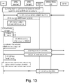
- Fig. 13 illustrates a procedure for a solution where the UE initiates request for unicast delivery of GC data/media upon eNB indication to UE about loss of (e)MBMS service in the target cell.
- the handover decision is taken from the source eNB1 according to the legacy mobility concept in 3GPP.
- the initial assumption is that. the UE receives the GC data/media via a multicast delivery from the content provider (GC-AS) via an (e)MBMS bearer service.
- GC-AS content provider
- e eMBMS bearer service
- the following steps from Fig. 13 describe the details of this solution:
- the UE exchanges capabilities about support of (e)MBMS bearer service continuity. This capability exchange may happen either (1) during the Attach procedure, e.g. the UE includes the capability as part of the Attach request message, or (2) when the UE starts receiving (e)MBMS bearer services as explicit NAS signaling exchange to MME or RRC signaling to serving eNB.
- step (2) in Fig. 13 the eNB1 maintains information about the (e)MBMS bearer service(s) which the UE currently receives.
- the eNB can obtain this information either from the UE or from the MME.
- the eNB1 stores an enhanced UE context including information of the (e)MBMS bearer service(s) currently received by the UE.
- the eNB1 stores the TMGI(s) of the (e)MBMS services received by the UE.
- the eNB1 does not inform the UE about the (e)MBMS bearer service(s) configuration of the neighbor cells.
- step (3) the UE performs the normal radio measurements of the neighbor cells as part of the mobility procedure in CONNECTED state.
- the UE detects threshold for handover event, the UE sends the measurement reports to the source eNB1. This step does not require any changes to the UE.
- step (4) based on the measurement report, the source eNB detects whether the possible target cell offers the MBMS service which the UE actively listens.
- eNB1 has stored information whether and which MBMS services (TMGIs) are subscribed and actively received by the UE.
- TMGIs MBMS services
- the source eNB1 either maintains information about the neighbor cells and which neighbor cells offer which MBSFN service, or first requests the target eNB2 (according to the measurement report from the UE) or the MME/MCE about the offered MBSFN services. After the reply from the target eNB or MME/MCE, the source eNB determines if the possible target cell offers the MBSFN service.
- step (5) if the source eNB determines that the target cell does not offer the (e)MBMS service(s), the source eNB informs the UE (e.g. via RRC signaling message) about "NO activated eMBMS service in target cell", i.e. the target eNB2 is not part of the MBSFN area.
- the UE forwards this information from eNB1 internally from the RRC layer to the corresponding application (e.g. GC application) using the (e)MBMS service.
- This UE internal forwarding of the eNB1's indication may be performed in several ways. For instance, a special API between the RRC layer and application layer may be specified. Alternatively, the RRC layer may forward the indication to NAS layer; then NAS layer forwards the indication via a special API to the application layer.
- step (6.1) the UE's application initiates application level signaling to request the GC-AS to start unicast delivery of GC data/media.
- step (6.2) the GC-AS either (a) replies with application level signaling to the UE to confirm the reception and processing of the UE's request; or (b) the GC-AS starts sending data/media via unicast and the UE detects via reception of the data that the request was processed in the GC-AS.
- Step (7) can be observed as reply to the indication from step (5).
- the UE indicates to the source eNB1 that the indication from step (5) was successfully received and processed, so that eNB1 can proceed with the handover procedure.
- the eNB1 delays the sending of "Handover" command to the UE in order to give the opportunity to UE and GC-AS to establish (or at least partially establish) the unicast delivery path with corresponding EPS bearer establishment. There could be several options for determining the delay time.
- the eNB1 can wait until the UE indicates that it is "ready" for handover as explained above, or/and the eNB1 can wait for a given configurable time and after expiring of this time, the eNB1 can proceed with the handover procedure, i.e. sending Handover command message to the UE. Applying both options together would avoid waiting too long until the UE acknowledges the processing of the eNB1's indication from step (5).
- step (8) eNB1 initiates the handover procedure according to 3GPP TS23.401.
- the UE After completing the handover from eNB1 to eNB2, the UE receives the GC data/media via unicast delivery from the GC-AS via the eNB2.
- eNB1 sends a modified/extended Handover Command message (which could be an RRC message) to the UE which contains the same or similar indication, i.e. "NO activated eMBMS service in target cell”.
- a modified/extended Handover Command message (which could be an RRC message)
- the UE After receiving such an extended Handover Command message, the UE first initiates application level signaling to the GC-AS in order to request unicast delivery of the GC session data.
- This application level signaling may be the same as described above in connection with steps (6.1) and (6.2) of Fig. 13 .
- the UE executes the handover procedure to eNB2.
- the indication "NO activated eMBMS service in target cell” is provided to the UE in the Handover Command message and the UE performs the application level signaling in steps (6.1) and (6.2) before starting the synchronization with the target cell.
- the UE can be pre-configured with neighbor cells info for (e)MBMS services, i.e. whether the neighbor cells support the (e)MBMS service currently received for GC data.
- neighbor cells info for (e)MBMS services i.e. whether the neighbor cells support the (e)MBMS service currently received for GC data.
- Such a configuration in the UE can be performed either by the eNB to which the UE is currently connected (called source eNB) or by the MME to which the UE currently has a NAS connection (usually the MME knows about the configured (e)MBMS services in the E-UTRAN from the MCE). If such a configuration is performed in the UE, then there is no need to use the explicit indication as shown in Fig. 13 or to use an extended Handover Command.
- the eNB1 would send non-modified Handover Command message (i.e.
- GPRS General Packet Radio Service
- E-UTRAN Evolved Universal Terrestrial Radio Access Network
- the main benefits of the above embodiments are 1) service continuity, i.e. no data flow interruption is perceived by the application layer and 2) the solution works even in case of (e)MBMS services provided in only one cell or a small number of cells where all cells can be boundary cells.
- First that may be an increased delay of the handover execution procedure, as the application level signaling, i.e. steps (6.1) and (6.2) of Fig. 13 , are performed after the handover preparation procedure and before the handover synchronization procedure (i.e. before the UE start the synchronization with the target eNB2).
- Second there is no network guarantee for the service continuity, i.e. the network doesn't know if the UE has successfully performed the application level signaling.
- One other aspect that considered in the context of embodiments of the present invention is the case where the UE moves into (e)MBMS bearer service (MBSFN area) coverage whereas unicast delivery of the GC session data was used before the movement.
- MMSFN area MMS bearer service
- the problem is how does the UE perceive that the GC service data that is currently received via unicast delivery is also distributed over (e)MBMS bearer service.
- One possible solution would be to configure the UE via application level signaling (i.e. from GC-AS) with cell IDs in which the GC service is distributed via (e)MBMS bearer service. Then an UE internal API between the Access Stratum and the Application layer is needed in order to forward information about the current cell ID from the 3GPP transport layer to the application layer.
- the application layer determines that the UE entered a cell which is a part of the MBSFN area, the UE can initiate application-level signaling to the GC-AS to request multicast delivery and stop the unicast delivery.
- a solution to overcome the above disadvantages is proposed herewith which is based on indication provided to a UE receiving GC service via unicast delivery by the 3GPP network (using 3GPP signaling means like NAS signaling or RRC signaling) when the UE moves into the MBSFN area coverage.
- the UE during GC service setup procedure indicates to the MME the service/session group identifier (GC-ID) identifying the GC service session.
- GC-ID can be the APN used for the GC service, another example can be a special call ID.
- the MME should maintain UE's context storing the currently activate GC-ID. Other UEs using the same GC service should use the same GC-ID.
- the MME should maintain a mapping of the (e)MBMS bearer service's TMGI with the GC-ID.
- the MME determines that the unicast EPS bearer established for GC service over eNB2 is used for the same service as the (e)MBMS bearer service provided by eNB2 as well. Since the MME knows the all cells configured for the (e)MBMS bearer service, when a UE (in CONNECTED state) moves into a cell transmitting the (e)MBMS bearer service having GC-ID same as the UE's currently used GC-ID, the MME determines (based on the GC-ID) that the UE receives the same GC service data over unicast bearer which is also provided over the (e)MBMS bearer service.
- the MME can indicate to the UE that the GC service data is available over (e)MBMS service in the current cell and the MME can indicate (e)MBMS's TMGI to the UE.
- the UE initiates 3GPP procedures, e.g. signaling to BMSC to receive the security parameters and scanning the SIB for (e)MBMS resources as described in 3GPP TS23.246, to start receiving the GC data/media via (e)MBMS bearer service. Additionally the UE would perform application-level signaling to GC-AS to indicate the reception of the GC service over (e)MBMS bearer service and to indicate to GC-AS that the unicast delivery can be terminated.
- 3GPP procedures e.g. signaling to BMSC to receive the security parameters and scanning the SIB for (e)MBMS resources as described in 3GPP TS23.246, to start receiving the GC data/media via (e)MBMS bearer service.
- the UE would perform application-level signaling to GC-
- Fig. 14 shows the solution explained above about maintaining the service continuity when the UE enters MBSFN area and switch from unicast to multicast delivery is performed.
- the thick arrows in Fig. 14 show data flow and the thin arrows show the signaling flow between the functional entities.
- the steps from Fig. 14 are described as follows:
- the UE establishes GC service over eNB1.
- eNB1 is not part of the (e)MBMS bearer service or no (e)MBMS bearer service has been established yet, the GC service data delivery from GC-AS to UE is via unicast bearer.
- the MME may use the APN of the Group communication session as GC-ID.
- the UE optionally may indicate a GC-ID for the specific Group communication session.
- eNB2 is part of (e)MBMS bearer service that can be established before or after the UE established the GC service via unicast delivery.
- the (e)MBMS bearer service can be seen as preestablished prior to the handover procedure.
- the MME maintains the GC-ID of the established (e)MBMS bearer service (e.g. to eNB2).
- the MME is able to map the relation of the GC-ID of the unicast bearers with the GC-ID of the multicast bearers.
- information exchange between the MMEs e.g. via S10 reference point, is exchanged in order to update each other about the available (e)MBMS bearer service (and the corresponding GC-IDs) in the MME pool area.
- step (3) the UE performs a handover from eNB1 to eNB2. This is a handover procedure as described in [2]. Usually after the handover procedure the UE receives the GC service data over unicast delivery via eNB2.
- step (4) if the signaling exchange described in step (4) is performed during the handover procedure step (3) itself, it is possible that the UE starts pretty soon the reception of the GC service data over (e)MBMS bearer in eNB2's cell, and thus, the UE can immediately start to perform steps (6.1) and (6.2). With other words, steps (3) and (4) can be integrated during the handover procedure and the GC service reception over unicast delivery can be obsolete, as the UE can quickly join the (e)MBMS bearer service.
- step (4) the MME determines that the unicast EPS bearer established for GC service over eNB2 is used for the same service as the (e)MBMS bearer service provided by eNB2 as well.
- the MME determines that the UE participates the same GC session as the one provided over the (e)MBMS bearer service.
- the MME determines that the GC-ID of the unicast bearer and the (e)MBMS bearer service are the same.
- the MME After determining the relation of the GC services over unicast EPS bearer and (e)MBMS bearer service over eNB2, the MME indicates to the UE that the GC service can be obtained via (e)MBMS bearer service, and more specifically the MME indicates the TMGI of the (e)MBMS bearer service. It is assumed that the GC service received by the UE and the GC service distributed over (e)MBMS bearer service are the same, i.e. if the GC service received by the UE includes multiple public safety groups then the GC service over the (e)MBMS bearer service should include the same public safety groups.
- the MME shall have means to determine the exact mapping of GC service distributed over unicast EPS bearer and (e)MBMS bearer.
- the MME can use NAS signaling message (e.g. NAS Information message) to indicate to the UE the available (e)MBMS bearer service and the corresponding TMGI.
- NAS signaling message e.g. NAS Information message
- step (4) can be a separate signaling procedure between MME and UE as described in Fig. 14 , but it can also be performed during the handover procedure in step (3). With other words the signaling from MME to UE may be a part of the handover procedure.
- step (5) after the UE has been indicated about the available (e)MBMS bearer service in the current cell of eNB2, the UE starts scanning the broadcasted cell system information (SIB) to discover the radio resources at which the (e)MBMS bearer service is broadcasted. Additionally, the UE may initiate procedures to join the (e)MBMS bearer service as described in 3GPP TS23.246. After steps (5) and (5.1) the UE is able to receive the GC service via (e)MBMS bearer service broadcasted over MRB (P2M radio bearer).
- SIB broadcasted cell system information
- steps (6.1) the UE uses application-level signaling to inform the GC-AS about the ability to receive GC service data over (e)MBMS bearer service.
- step (6.2) the GC-AS can acknowledge the reception of the message in step (6.1) and to terminate the transmission of GC service data over unicast delivery.
Claims (15)
- Procédé de fourniture de continuité de service de multidiffusion/radiodiffusion pour des terminaux mobiles dans un réseau d'accès radio,
dans lequel lesdits terminaux mobiles s'enregistrent auprès d'une station de base dudit réseau d'accès radio concernant ledit service de multidiffusion/radiodiffusion et dans lequel ladite station de base transmet des données liées à un service de multidiffusion/radiodiffusion en tant que communications de groupe auxdits terminaux mobiles enregistrés,
dans lequel ledit service de multidiffusion/radiodiffusion est un service multidiffusion/radiodiffusion multimédia, MBMS,
dans lequel un terminal mobile réalise des mesures radio liées au MBMS, le procédé étant caractérisé en ce que
une décision sur des actions à réaliser par ladite station de base et/ou par ledit terminal mobile pour conserver une transmission/réception fiable desdites données liées au MBMS à/par ledit terminal mobile est prise par ladite station de base ou par ledit terminal mobile d'après les résultats desdites mesures radio liées au MBMS et d'après une topologie de service MBMS dans des cellules voisines et/ou des possibilités de transmission unidiffusion, et
une entité de gestion de mobilité, MME, dudit réseau d'accès radio, lorsqu'elle est informée par ledit terminal mobile d'un démarrage réussi de réception de données MBMS par ledit terminal mobile, signale une mise à jour du contexte dudit terminal mobile incluant des informations des services de porteuse MBMS actuellement reçus du terminal mobile à ladite station de base,
dans lequel ladite station de base, d'après la mise à jour du contexte dudit terminal mobile signalé par ladite MME, détermine s'il faut configurer ledit terminal mobile pour envoyer des rapports de mesure radio liée au MBMS à ladite station de base. - Procédé selon la revendication 1, dans lequel ledit terminal mobile transmet lesdits résultats de mesure radio liée au MBMS à ladite station de base, de préférence périodiquement à des intervalles de temps prédéfinis ou déclenchés par un événement particulier d'un groupe d'événements prédéfinis.
- Procédé selon la revendication 1 ou 2, dans lequel les mesures radio dudit terminal mobile utilisées pour des procédures de mobilité sont étendues pour inclure en outre des informations concernant la qualité de signal radio MBMS, et/ou
dans lequel lesdites mesures radio liées au MBMS incluent des mesures sur l'intensité de signal de porteuse radio MBMS, et/ou sur des erreurs de décodage et/ou des taux d'erreur de bloc de données de porteuse radio MBMS reçues. - Procédé selon l'une quelconque des revendications 1 à 3, dans lequel un réseau monofréquence de service de multidiffusion radiodiffusion multimédia, MBSFN, est configuré et dans lequel le symbole de porteuse MBSFN est employé en tant que signal de référence pour générer les informations liées au MBMS dans des rapports de mesure radio du terminal mobile transmis à ladite station de base.
- Procédé selon l'une quelconque des revendications 1 à 4, dans lequel ledit terminal mobile transmet les rapports de mesure radio liée au MBMS à ladite station de base au moyen d'une signalisation de commande de ressource radio, RRC.
- Procédé selon l'une quelconque des revendications 1 à 5, dans lequel la détermination de ladite station de base pour savoir s'il faut configurer ledit terminal mobile pour envoyer des rapports de mesure radio liée au MBMS à ladite station de base se fait pour chacune desdites porteuses radio MBMS activées par ledit terminal mobile individuellement, et/ou
dans lequel ladite station de base configure un terminal mobile, de préférence lorsque ledit terminal mobile relie la réception du MBMS à des seuils liés au MBMS, de préférence liés à l'intensité de signal radio, au taux d'erreur de paquet et/ou au taux d'erreur de bloc. - Procédé selon l'une quelconque des revendications 1 à 6, dans lequel des seuils liés au MBMS sont employés par ledit terminal mobile pour déclencher des actions afin d'éviter des pertes de paquets de données MBMS,
dans lequel de préférence lesdits seuils liés au MBMS sont configurés par ladite station de base. - Procédé selon la revendication 7, dans lequel ledit terminal mobile lance une signalisation de couche d'application pour demander une transmission unidiffusion depuis un serveur d'envoi lors de la détection que lesdits seuils liés au MBMS configurés sont dépassés/insuffisants.
- Procédé selon l'une quelconque des revendications 1 à 8, dans lequel ladite station de base, après que ledit terminal mobile signale des conditions médiocres de réception MBMS chutant en dessous ou dépassant des seuils prédéfinis, détermine des actions pour conserver la continuité de service de réception de données MBMS, et/ou
dans lequel une action déterminée par ladite station de base comporte le déclenchement dudit terminal mobile pour qu'il réalise une signalisation de couche d'application pour demander une livraison unidiffusion, et/ou
dans lequel une action déterminée par ladite station de base comporte le mappage des données MBMS sur des porteuses radio unidiffusion existantes,
dans lequel de préférence ledit mappage est appliqué dans des cas où le terminal mobile est supposé récupérer dans un intervalle de temps prédéfini des médiocres conditions radio pour une transmission MBMS. - Procédé selon l'une quelconque des revendications 1 à 9, dans lequel ladite station de base informe ledit terminal mobile de la transmission des données MBMS sur une porteuse radio par défaut particulière, et/ou
dans lequel ladite station de base détermine et applique des priorités d'ordonnancement différentes pour la transmission de données MBMS et de données unidiffusion sur la même porteuse radio par défaut, et/ou
dans lequel ladite station de base modifie dynamiquement lesdites priorités d'ordonnancement différentes selon la situation de charge dans la cellule radio respective. - Procédé selon l'une quelconque des revendications 1 à 10, dans lequel une action déterminée par ladite station de base inclut le transfert dudit terminal mobile à une station de base d'une cellule voisine.
- Station de base pour fournir une continuité de service multidiffusion/radiodiffusion pour des terminaux mobiles dans un réseau d'accès radio, en particulier pour exécuter un procédé selon l'une quelconque des revendications 1 à 11,
dans laquelle ladite station de base est configurée pour transmettre des données liées à un service de multidiffusion/radiodiffusion en tant que communications de groupe à des terminaux mobiles enregistrés auprès de ladite station de base concernant ledit service de multidiffusion/radiodiffusion,
dans laquelle ledit service de multidiffusion/radiodiffusion est un service multidiffusion/radiodiffusion multimédia, MBMS, et
dans laquelle ladite station de base est en outre configurée pour recevoir des résultats de mesures radio liée au MBMS, réalisées par un terminal mobile, et
la station de base est caractérisée en ce qu'elle est configurée pour, d'après les résultats de mesure reçus et d'après une topologie de service MBMS dans des cellules voisines et/ou des possibilités de transmission unidiffusion, prendre une décision sur des actions à réaliser pour conserver une transmission fiable desdites données liées au MBMS audit terminal mobile, et
pour recevoir en provenance d'une entité de gestion de mobilité, MME, dudit réseau d'accès radio, lorsque ladite MME est informée par ledit terminal mobile d'un démarrage réussi de réception de données MBMS par ledit terminal mobile, une mise à jour d'un contexte dudit terminal mobile incluant des informations des services de porteuse MBMS actuellement reçus du terminal mobile,
dans laquelle ladite station de base est en outre configurée pour déterminer, d'après la mise à jour du contexte dudit terminal mobile signalé par ladite MME, s'il faut configurer ledit terminal mobile pour envoyer des rapports de mesure radio liée au MBMS à ladite station de base. - Station de base selon la revendication 12, configurée pour appliquer un mécanisme d'ordonnancement qui subdivise des paquets de la même porteuse radio afin de permettre des traitements d'ordonnancement différents de données MBMS d'une part et de données unidiffusion d'autre part.
- Système doté d'une prise en charge de continuité de service multidiffusion/radiodiffusion pour des terminaux mobiles dans un réseau d'accès radio, dans lequel ledit service multidiffusion/radiodiffusion est un service multidiffusion/radiodiffusion multimédia, MBMS, le système comprenant :une station de base, etun terminal mobile, ledit terminal mobile étant configuré pours'enregistrer auprès de ladite station de base concernant ledit service multidiffusion/radiodiffusion et pour recevoir en provenance de ladite station de base des données liées au service multidiffusion/radiodiffusion en tant que communications de groupe, etréaliser des mesures radio liées au MBMS,caractérisé en ce que ladite station de base ou ledit terminal mobile est configuré(e) pour prendre une décision sur des actions à réaliser par ladite station de base ou ledit terminal mobile pour conserver une transmission/réception fiable desdites données liées au MBMS à/par ledit terminal mobile d'après les résultats desdites mesures radio liées au MBMS et d'après une topologie de service MBMS dans des cellules voisines et/ou des possibilités de transmission unidiffusion,et en ce que le système comprend en outre une entité de gestion de mobilité, MME,dans lequel ladite MME est configurée, lorsqu'elle est informée par ledit terminal mobile d'un démarrage réussi de réception de données MBMS par ledit terminal mobile, pour signaler une mise à jour du contexte dudit terminal mobile incluant des informations des services de porteuse MBMS actuellement reçus du terminal mobile à ladite station de base, etdans lequel ladite station de base est configurée pour déterminer, d'après la mise à jour du contexte dudit terminal mobile signalé par ladite MME, s'il faut configurer ledit terminal mobile pour envoyer des rapports de mesure radio liée au MBMS à ladite station de base.
- Système selon la revendication 14, dans lequel ledit terminal mobile est configuré pour réaliser des mesures radio liées au MBMS en tant qu'extension desdites mesures radio dudit terminal mobile utilisées pour des procédures de mobilité, et/ou
dans lequel ledit terminal mobile est configuré pour réaliser l'une desdites actions en lançant une signalisation de couche d'application pour demander une transmission unidiffusion à un serveur d'envoi lors de la détection que des seuils liés au MBMS configurés dans ledit terminal mobile par ladite station de base, de préférence liés à une intensité de signal radio, un taux d'erreur de paquet et/ou un taux d'erreur de bloc, sont dépassés/insuffisants, et/ou
dans lequel ledit terminal mobile comprend une fonctionnalité interne pour acheminer toute indication reçue en provenance de ladite station de base à l'application impactée ou concernée ou au module/à la couche interne.
Priority Applications (1)
| Application Number | Priority Date | Filing Date | Title |
|---|---|---|---|
| EP14747308.6A EP3017616B1 (fr) | 2013-07-01 | 2014-07-01 | Procédé de fourniture de continuité de service de diffusion groupée/générale à des terminaux mobiles |
Applications Claiming Priority (6)
| Application Number | Priority Date | Filing Date | Title |
|---|---|---|---|
| EP13174549 | 2013-07-01 | ||
| EP13181556 | 2013-08-23 | ||
| EP13183988 | 2013-09-11 | ||
| EP13190350 | 2013-10-25 | ||
| EP14747308.6A EP3017616B1 (fr) | 2013-07-01 | 2014-07-01 | Procédé de fourniture de continuité de service de diffusion groupée/générale à des terminaux mobiles |
| PCT/EP2014/063983 WO2015000912A1 (fr) | 2013-07-01 | 2014-07-01 | Procédé de fourniture de continuité de service de diffusion groupée/diffusion générale à des terminaux mobiles |
Publications (2)
| Publication Number | Publication Date |
|---|---|
| EP3017616A1 EP3017616A1 (fr) | 2016-05-11 |
| EP3017616B1 true EP3017616B1 (fr) | 2018-12-05 |
Family
ID=51265652
Family Applications (1)
| Application Number | Title | Priority Date | Filing Date |
|---|---|---|---|
| EP14747308.6A Active EP3017616B1 (fr) | 2013-07-01 | 2014-07-01 | Procédé de fourniture de continuité de service de diffusion groupée/générale à des terminaux mobiles |
Country Status (3)
| Country | Link |
|---|---|
| US (2) | US10219245B2 (fr) |
| EP (1) | EP3017616B1 (fr) |
| WO (1) | WO2015000912A1 (fr) |
Families Citing this family (81)
| Publication number | Priority date | Publication date | Assignee | Title |
|---|---|---|---|---|
| US10219245B2 (en) * | 2013-07-01 | 2019-02-26 | Nec Corporation | Method for providing multicast/broadcast service continuity for mobile terminals |
| US10129710B2 (en) | 2013-09-26 | 2018-11-13 | Lg Electronics Inc. | Method and apparatus for indicating stopping MBMS transmission in wireless communication system |
| CN104640077B (zh) * | 2013-11-08 | 2019-10-11 | 中兴通讯股份有限公司 | 一种集群通信的方法及系统、用户设备和网络侧设备 |
| US20150172066A1 (en) * | 2013-12-13 | 2015-06-18 | Qualcomm Incorporated | Practical implementation aspects of unicast fetch for http streaming over embms |
| CN105009638B (zh) * | 2014-01-03 | 2019-10-01 | 华为技术有限公司 | 一种用户设备切换方法及基站 |
| US20160323846A1 (en) * | 2014-01-06 | 2016-11-03 | Lg Electronics Inc. | Method and apparatus for providing group communication service enabler (gcse) service in wireless communication system |
| JP2015142332A (ja) * | 2014-01-30 | 2015-08-03 | ソニー株式会社 | 装置 |
| EP3100495B1 (fr) * | 2014-01-31 | 2018-11-28 | Nokia Technologies Oy | Mesures bler pour mbms |
| CN104955086A (zh) * | 2014-03-24 | 2015-09-30 | 中兴通讯股份有限公司 | Mbms差错处理方法、通信节点及通信系统 |
| CN105324971B (zh) * | 2014-05-23 | 2019-03-08 | 华为技术有限公司 | 一种绑定注册和数据转发方法、相关设备及网络系统 |
| US10772073B2 (en) | 2014-07-18 | 2020-09-08 | Samsung Electronics Co., Ltd. | Synchronization method and device for device-to-device communication in wireless communication system |
| CN104301931A (zh) * | 2014-09-24 | 2015-01-21 | 中兴通讯股份有限公司 | 拥塞/过载的控制方法,系统,装置和基站 |
| US10756914B2 (en) * | 2014-09-26 | 2020-08-25 | Samsung Electronics Co., Ltd. | Broadcast resource congestion control method and apparatus for use in wireless communication system |
| WO2016068664A1 (fr) | 2014-10-31 | 2016-05-06 | Samsung Electronics Co., Ltd. | Procédé et appareil de transmission de canal de commande dans un système d'agrégation de porteuses intracellulaire |
| US9763060B2 (en) * | 2014-11-11 | 2017-09-12 | Alcatel Lucent | Streaming unicast services to multiple user equipment |
| US10820314B2 (en) | 2014-12-12 | 2020-10-27 | Qualcomm Incorporated | Traffic advertisement in neighbor aware network (NAN) data path |
| US10827484B2 (en) | 2014-12-12 | 2020-11-03 | Qualcomm Incorporated | Traffic advertisement in neighbor aware network (NAN) data path |
| US9949236B2 (en) * | 2014-12-12 | 2018-04-17 | Qualcomm Incorporated | Traffic advertisement in neighbor aware network (NAN) data path |
| WO2016111522A1 (fr) * | 2015-01-08 | 2016-07-14 | 주식회사 케이티 | Procédé de transmission et de réception de données multi-transmission mono-cellule, et appareil associé |
| US9736774B2 (en) * | 2015-01-30 | 2017-08-15 | Huawei Technologies Co., Ltd. | Apparatus and method for a wireless device to receive data in an eco state |
| EP3073779A1 (fr) * | 2015-03-23 | 2016-09-28 | Gemalto M2M GmbH | Procédé pour faire fonctionner un dispositif mtc supportant des réseaux à auto-organisation |
| US20160353340A1 (en) * | 2015-05-29 | 2016-12-01 | Qualcomm Incorporated | Inter-rat (radio access technology) and intra-rat measurement reporting |
| US10798623B2 (en) | 2015-06-26 | 2020-10-06 | Apple Inc. | Method for processing radio signals and mobile terminal device |
| EP3335442A4 (fr) * | 2015-08-13 | 2019-01-16 | Nokia Solutions and Networks Oy | Procédé et appareil pour réduire une durée d'interruption de service dans un système point à multipoint à cellule unique |
| EP3328124B1 (fr) * | 2015-08-20 | 2020-01-29 | Huawei Technologies Co., Ltd. | Procédé et appareil pour délivrer un service mbms avec qualité de service par un terminal relai |
| CN107113909A (zh) * | 2015-09-15 | 2017-08-29 | 华为技术有限公司 | 一种收发应用层参数信息的方法和设备 |
| WO2017089183A1 (fr) | 2015-11-27 | 2017-06-01 | British Telecommunications Public Limited Company | Synchronisation de contenu multimédia |
| US9913249B2 (en) * | 2015-12-09 | 2018-03-06 | At&T Intellectual Property I, L.P. | Method and system for selective paging of wireless devices using a cellular broadcast service |
| GB2548893B (en) * | 2016-03-31 | 2020-01-08 | British Telecomm | Mobile communications network |
| WO2017167835A1 (fr) * | 2016-03-31 | 2017-10-05 | British Telecommunications Public Limited Company | Réseau de communication mobile |
| US10728714B2 (en) * | 2016-03-31 | 2020-07-28 | British Telecommunications Public Limited Company | Mobile communications network |
| US11477700B2 (en) * | 2016-03-31 | 2022-10-18 | British Telecommunications Public Limited Company | Mobile communications network |
| US9894458B2 (en) * | 2016-04-25 | 2018-02-13 | Verizon Patent And Licensing Inc. | Optimizing MTC updates using MBMS |
| WO2017194114A1 (fr) * | 2016-05-12 | 2017-11-16 | Telefonaktiebolaget Lm Ericsson (Publ) | Évaluation de qualité d'un support mbms |
| EP3479622B1 (fr) | 2016-06-29 | 2019-11-13 | British Telecommunications Public Limited Company | Réseau de communications mobile pour diffusion multicast-broadcast |
| GB2551751A (en) * | 2016-06-29 | 2018-01-03 | British Telecomm | Mobile communications network |
| US11317250B2 (en) * | 2016-07-11 | 2022-04-26 | Lg Electronics Inc. | Method for transmitting MBMS interest indication message by terminal and device supporting same |
| RU2737202C2 (ru) * | 2016-07-27 | 2020-11-25 | Шарп Кабусики Кайся | Системная информация по запросу для беспроводной связи |
| WO2018024395A1 (fr) | 2016-08-04 | 2018-02-08 | British Telecommunications Public Limited Company | Réseau de communication mobile |
| KR102174043B1 (ko) * | 2016-11-01 | 2020-11-04 | 텔레폰악티에볼라겟엘엠에릭슨(펍) | 서비스 인터럽션 보고 |
| CN110169038B (zh) * | 2017-01-09 | 2022-04-22 | 诺基亚技术有限公司 | 用于在多播/广播网络中的协调内容传递的方法和装置 |
| BR112019015810A2 (pt) * | 2017-02-06 | 2020-03-31 | Qualcomm Incorporated | Determinação de capacidade e cobertura para serviço de difusão e multidifusão de multimídia |
| CN110583084B (zh) | 2017-05-05 | 2023-04-07 | 瑞典爱立信有限公司 | 无线电网络中的方法和装置 |
| CN108990112B (zh) * | 2017-05-31 | 2021-01-15 | 华为技术有限公司 | 通信网络中的任务处理方法和通信装置 |
| US10645228B2 (en) * | 2017-06-26 | 2020-05-05 | Apple Inc. | Adaptability in EVS codec to improve power efficiency |
| CN109547944A (zh) * | 2017-09-21 | 2019-03-29 | 华为技术有限公司 | 数据传输的方法及装置 |
| CN109756846A (zh) * | 2017-11-06 | 2019-05-14 | 成都鼎桥通信技术有限公司 | 群组通信的补包方法和系统 |
| US20220046505A1 (en) * | 2018-01-17 | 2022-02-10 | T-Mobile Usa, Inc. | Telecommunications Network Bearer Allocation and Deallocation |
| CN111771422B (zh) * | 2018-02-26 | 2023-05-09 | 诺基亚技术有限公司 | 用于无线网络的多播业务区域管理和移动性 |
| WO2019223005A1 (fr) | 2018-05-25 | 2019-11-28 | Qualcomm Incorporated | Architecture de multidiffusion en mode mixte |
| CN110581727A (zh) | 2018-06-08 | 2019-12-17 | 英国电讯有限公司 | 无线电信网络 |
| EP3881459B1 (fr) | 2018-11-12 | 2023-12-13 | Nokia Technologies Oy | Procédé et appareil de distribution efficiente de flux source et de correction d'erreur directe dans des systèmes prenant en charge une transmission mixte en monodiffusion et multidiffusion |
| CN111510964B (zh) * | 2019-01-31 | 2021-09-07 | 华为技术有限公司 | 一种通信方法及装置 |
| CN111586084B (zh) * | 2019-02-18 | 2023-04-07 | 瑞典爱立信有限公司 | 用于发现v2x通信的应用服务器和/或服务的方法、装置 |
| US11477687B2 (en) * | 2019-08-29 | 2022-10-18 | Qualcomm Incorproated | Delivery of broadcast services using different broadcast/multicast radio bearer modes |
| EP4021127A4 (fr) * | 2019-09-20 | 2023-08-30 | KT Corporation | Procédé et dispositif de commutation de données de mbs |
| US11368818B2 (en) * | 2019-12-10 | 2022-06-21 | Indian Institute Of Technology Bombay | Methods and systems for using multi-connectivity for multicast transmissions in a communication system |
| US11627502B2 (en) * | 2019-12-16 | 2023-04-11 | Qualcomm Incorporated | Measurements for multicast/broadcast service continuity |
| EP4084405A4 (fr) * | 2020-01-06 | 2023-03-29 | Guangdong Oppo Mobile Telecommunications Corp., Ltd. | Procédé de commutation de service, terminal et dispositif réseau |
| CN113271551B (zh) * | 2020-02-17 | 2022-07-05 | 大唐移动通信设备有限公司 | 一种数据流传输方法、终端和网络侧设备 |
| CN115244899A (zh) * | 2020-03-20 | 2022-10-25 | 高通股份有限公司 | 用于无线通信中的多播和单播汇聚的技术 |
| CN113452487B (zh) * | 2020-03-25 | 2022-09-13 | 展讯通信(上海)有限公司 | 数据传输方法及装置 |
| CN115580893A (zh) * | 2020-04-03 | 2023-01-06 | 上海朗帛通信技术有限公司 | 一种被用于无线通信的方法和设备 |
| CN116321016A (zh) * | 2020-04-15 | 2023-06-23 | 上海朗帛通信技术有限公司 | 一种被用于无线通信的节点中的方法和装置 |
| EP4142399A4 (fr) * | 2020-05-11 | 2023-10-11 | Samsung Electronics Co., Ltd. | Procédé et dispositif permettant de configurer une bwp pour une continuité de service de mbs dans un système de communication sans fil |
| KR20210138395A (ko) * | 2020-05-12 | 2021-11-19 | 삼성전자주식회사 | 이동 통신 시스템에서 mbs 수신을 위한 bwp 전환 방법 및 장치 |
| CN116134932A (zh) * | 2020-05-28 | 2023-05-16 | 京瓷株式会社 | 通信控制方法和用户设备 |
| CN113950042A (zh) * | 2020-07-17 | 2022-01-18 | 维沃移动通信有限公司 | 识别方法、发送方法及相关设备 |
| EP4176687A4 (fr) * | 2020-08-06 | 2024-01-10 | Samsung Electronics Co Ltd | Procédés et systèmes de gestion de continuité de service mbs pour un équipement utilisateur |
| EP4183146A4 (fr) * | 2020-08-07 | 2024-04-17 | Jrd Communication Shenzhen Ltd | Appareil et procédé pour service de multidiffusion/diffusion |
| US20240064591A1 (en) * | 2020-09-03 | 2024-02-22 | Toyota Jidosha Kabushiki Kaisha | Multicast broadcast service continuity in connected state |
| CN114339902A (zh) * | 2020-09-29 | 2022-04-12 | 北京紫光展锐通信技术有限公司 | 业务切换指示、接收方法及装置、存储介质、基站、终端 |
| WO2022154552A1 (fr) * | 2021-01-15 | 2022-07-21 | Samsung Electronics Co., Ltd. | Procédé et système d'opération de mesure pour des services de multidiffusion et de diffusion en 5g |
| CN117242875A (zh) * | 2021-04-01 | 2023-12-15 | 上海诺基亚贝尔股份有限公司 | 体验质量测量的控制 |
| KR20230172503A (ko) * | 2021-04-27 | 2023-12-22 | 삼성전자주식회사 | 무선 통신 시스템에서의 멀티캐스트 세션 시그널링 방법 및 장치 |
| WO2022236211A1 (fr) * | 2021-05-05 | 2022-11-10 | Qualcomm Incorporated | Échange de configuration de services de diffusion/multidiffusion pour la mobilité, réseau monofréquence et coordination d'interférence |
| US11910277B2 (en) | 2021-05-05 | 2024-02-20 | Qualcomm Incorporated | Multicast-broadcast services configuration exchange for mobility, single-frequency network and interference coordination |
| CN116193376B (zh) * | 2021-10-15 | 2023-12-29 | 华为技术有限公司 | 一种通信方法及装置 |
| CN115052302A (zh) * | 2022-07-14 | 2022-09-13 | 中国联合网络通信集团有限公司 | 测量控制方法、装置及存储介质 |
| CN115134833A (zh) * | 2022-07-14 | 2022-09-30 | 中国联合网络通信集团有限公司 | 测量方法、装置、存储介质及设备 |
| CN115134834A (zh) * | 2022-07-14 | 2022-09-30 | 中国联合网络通信集团有限公司 | 测量配置方法、装置、存储介质及设备 |
Family Cites Families (14)
| Publication number | Priority date | Publication date | Assignee | Title |
|---|---|---|---|---|
| US20030119452A1 (en) * | 2001-10-19 | 2003-06-26 | Samsung Electronics Co., Ltd. | Apparatus and method for controlling transmission power of downlink data channel in a mobile communication system supporting MBMS |
| FI20021755A0 (fi) * | 2002-10-02 | 2002-10-02 | Nokia Corp | Menetelmä ja järjestely yleislähetyksen vastaanottoedellytysten ilmaisemiseksi |
| JP4169281B2 (ja) * | 2005-05-27 | 2008-10-22 | 株式会社カシオ日立モバイルコミュニケーションズ | 通信端末 |
| CN101163260B (zh) * | 2006-10-14 | 2011-04-13 | 华为技术有限公司 | 一种控制承载变化的系统、装置和方法 |
| CN101346910B (zh) * | 2006-10-30 | 2012-12-19 | 华为技术有限公司 | 多媒体广播和组播业务中用户设备运行维护的测量方法 |
| CN101595661A (zh) | 2007-01-26 | 2009-12-02 | 日本电气株式会社 | 移动通信系统、终端设备、基站设备及数据通信方法 |
| CN101810023B (zh) * | 2007-09-26 | 2014-12-10 | 日本电气株式会社 | 无线通信系统和方法 |
| JP4964081B2 (ja) * | 2007-10-01 | 2012-06-27 | パナソニック株式会社 | 無線送信装置 |
| WO2009148370A1 (fr) * | 2008-06-05 | 2009-12-10 | Telefonaktiebolaget Lm Ericsson (Publ) | Procédé et équipement destinés à réaliser une préparation de diffusion individuelle pour une télévision sur ip |
| US8687537B2 (en) * | 2008-07-08 | 2014-04-01 | Sharp Kabushiki Kaisha | Communication system, reception device, and communication method |
| CN102075866B (zh) * | 2011-01-19 | 2014-06-25 | 大唐移动通信设备有限公司 | 设备切换方法及装置 |
| US9820109B2 (en) * | 2011-08-12 | 2017-11-14 | Kyocera Corporation | Mobile communication method, mobile terminal, radio base station, and program |
| US8644207B1 (en) * | 2011-08-19 | 2014-02-04 | Sprint Spectrum L.P. | Mixed carrier communication channel management |
| US10219245B2 (en) * | 2013-07-01 | 2019-02-26 | Nec Corporation | Method for providing multicast/broadcast service continuity for mobile terminals |
-
2014
- 2014-07-01 US US14/902,043 patent/US10219245B2/en active Active
- 2014-07-01 WO PCT/EP2014/063983 patent/WO2015000912A1/fr active Application Filing
- 2014-07-01 EP EP14747308.6A patent/EP3017616B1/fr active Active
-
2019
- 2019-01-11 US US16/245,269 patent/US10531430B2/en active Active
Non-Patent Citations (1)
| Title |
|---|
| None * |
Also Published As
| Publication number | Publication date |
|---|---|
| US20160374050A1 (en) | 2016-12-22 |
| WO2015000912A1 (fr) | 2015-01-08 |
| EP3017616A1 (fr) | 2016-05-11 |
| US10531430B2 (en) | 2020-01-07 |
| US20190166580A1 (en) | 2019-05-30 |
| US10219245B2 (en) | 2019-02-26 |
Similar Documents
| Publication | Publication Date | Title |
|---|---|---|
| US10531430B2 (en) | Method for providing multicast/broadcast service continuity for mobile terminals | |
| US10687179B2 (en) | Service continuity for group communication over LTE eMBMS | |
| JP6456941B2 (ja) | 発展型マルチメディアブロードキャストマルチキャストサービスにおけるグループ通信のためのサービス継続性 | |
| EP2745557B1 (fr) | Continuité de service pour un service de diffusion/multidiffusion multimédia (mbms) destiné à un équipement utilisateur (ue) en mode connecté rrc | |
| WO2016119634A1 (fr) | Sélection de porteuse pour communication de service de groupe et continuité de service | |
| US20230362595A1 (en) | Communication control method and user equipment | |
| WO2024034567A1 (fr) | Procédé de communication |
Legal Events
| Date | Code | Title | Description |
|---|---|---|---|
| PUAI | Public reference made under article 153(3) epc to a published international application that has entered the european phase |
Free format text: ORIGINAL CODE: 0009012 |
|
| 17P | Request for examination filed |
Effective date: 20151221 |
|
| AK | Designated contracting states |
Kind code of ref document: A1 Designated state(s): AL AT BE BG CH CY CZ DE DK EE ES FI FR GB GR HR HU IE IS IT LI LT LU LV MC MK MT NL NO PL PT RO RS SE SI SK SM TR |
|
| AX | Request for extension of the european patent |
Extension state: BA ME |
|
| DAX | Request for extension of the european patent (deleted) | ||
| STAA | Information on the status of an ep patent application or granted ep patent |
Free format text: STATUS: EXAMINATION IS IN PROGRESS |
|
| 17Q | First examination report despatched |
Effective date: 20170207 |
|
| RAP1 | Party data changed (applicant data changed or rights of an application transferred) |
Owner name: NEC LABORATORIES EUROPE GMBH |
|
| GRAP | Despatch of communication of intention to grant a patent |
Free format text: ORIGINAL CODE: EPIDOSNIGR1 |
|
| STAA | Information on the status of an ep patent application or granted ep patent |
Free format text: STATUS: GRANT OF PATENT IS INTENDED |
|
| RIC1 | Information provided on ipc code assigned before grant |
Ipc: H04W 72/08 20090101ALN20180709BHEP Ipc: H04W 36/00 20090101ALI20180709BHEP Ipc: H04W 4/06 20090101AFI20180709BHEP Ipc: H04W 72/00 20090101ALI20180709BHEP Ipc: H04W 60/04 20090101ALN20180709BHEP |
|
| INTG | Intention to grant announced |
Effective date: 20180806 |
|
| GRAS | Grant fee paid |
Free format text: ORIGINAL CODE: EPIDOSNIGR3 |
|
| GRAA | (expected) grant |
Free format text: ORIGINAL CODE: 0009210 |
|
| STAA | Information on the status of an ep patent application or granted ep patent |
Free format text: STATUS: THE PATENT HAS BEEN GRANTED |
|
| AK | Designated contracting states |
Kind code of ref document: B1 Designated state(s): AL AT BE BG CH CY CZ DE DK EE ES FI FR GB GR HR HU IE IS IT LI LT LU LV MC MK MT NL NO PL PT RO RS SE SI SK SM TR |
|
| RAP1 | Party data changed (applicant data changed or rights of an application transferred) |
Owner name: NEC CORPORATION |
|
| REG | Reference to a national code |
Ref country code: GB Ref legal event code: FG4D |
|
| REG | Reference to a national code |
Ref country code: CH Ref legal event code: EP |
|
| REG | Reference to a national code |
Ref country code: AT Ref legal event code: REF Ref document number: 1074614 Country of ref document: AT Kind code of ref document: T Effective date: 20181215 |
|
| REG | Reference to a national code |
Ref country code: IE Ref legal event code: FG4D |
|
| REG | Reference to a national code |
Ref country code: DE Ref legal event code: R096 Ref document number: 602014037429 Country of ref document: DE |
|
| REG | Reference to a national code |
Ref country code: NL Ref legal event code: MP Effective date: 20181205 |
|
| REG | Reference to a national code |
Ref country code: AT Ref legal event code: MK05 Ref document number: 1074614 Country of ref document: AT Kind code of ref document: T Effective date: 20181205 |
|
| REG | Reference to a national code |
Ref country code: LT Ref legal event code: MG4D |
|
| PG25 | Lapsed in a contracting state [announced via postgrant information from national office to epo] |
Ref country code: FI Free format text: LAPSE BECAUSE OF FAILURE TO SUBMIT A TRANSLATION OF THE DESCRIPTION OR TO PAY THE FEE WITHIN THE PRESCRIBED TIME-LIMIT Effective date: 20181205 Ref country code: NO Free format text: LAPSE BECAUSE OF FAILURE TO SUBMIT A TRANSLATION OF THE DESCRIPTION OR TO PAY THE FEE WITHIN THE PRESCRIBED TIME-LIMIT Effective date: 20190305 Ref country code: LT Free format text: LAPSE BECAUSE OF FAILURE TO SUBMIT A TRANSLATION OF THE DESCRIPTION OR TO PAY THE FEE WITHIN THE PRESCRIBED TIME-LIMIT Effective date: 20181205 Ref country code: BG Free format text: LAPSE BECAUSE OF FAILURE TO SUBMIT A TRANSLATION OF THE DESCRIPTION OR TO PAY THE FEE WITHIN THE PRESCRIBED TIME-LIMIT Effective date: 20190305 Ref country code: HR Free format text: LAPSE BECAUSE OF FAILURE TO SUBMIT A TRANSLATION OF THE DESCRIPTION OR TO PAY THE FEE WITHIN THE PRESCRIBED TIME-LIMIT Effective date: 20181205 Ref country code: ES Free format text: LAPSE BECAUSE OF FAILURE TO SUBMIT A TRANSLATION OF THE DESCRIPTION OR TO PAY THE FEE WITHIN THE PRESCRIBED TIME-LIMIT Effective date: 20181205 Ref country code: LV Free format text: LAPSE BECAUSE OF FAILURE TO SUBMIT A TRANSLATION OF THE DESCRIPTION OR TO PAY THE FEE WITHIN THE PRESCRIBED TIME-LIMIT Effective date: 20181205 Ref country code: AT Free format text: LAPSE BECAUSE OF FAILURE TO SUBMIT A TRANSLATION OF THE DESCRIPTION OR TO PAY THE FEE WITHIN THE PRESCRIBED TIME-LIMIT Effective date: 20181205 |
|
| PG25 | Lapsed in a contracting state [announced via postgrant information from national office to epo] |
Ref country code: AL Free format text: LAPSE BECAUSE OF FAILURE TO SUBMIT A TRANSLATION OF THE DESCRIPTION OR TO PAY THE FEE WITHIN THE PRESCRIBED TIME-LIMIT Effective date: 20181205 Ref country code: RS Free format text: LAPSE BECAUSE OF FAILURE TO SUBMIT A TRANSLATION OF THE DESCRIPTION OR TO PAY THE FEE WITHIN THE PRESCRIBED TIME-LIMIT Effective date: 20181205 Ref country code: GR Free format text: LAPSE BECAUSE OF FAILURE TO SUBMIT A TRANSLATION OF THE DESCRIPTION OR TO PAY THE FEE WITHIN THE PRESCRIBED TIME-LIMIT Effective date: 20190306 Ref country code: SE Free format text: LAPSE BECAUSE OF FAILURE TO SUBMIT A TRANSLATION OF THE DESCRIPTION OR TO PAY THE FEE WITHIN THE PRESCRIBED TIME-LIMIT Effective date: 20181205 |
|
| PG25 | Lapsed in a contracting state [announced via postgrant information from national office to epo] |
Ref country code: NL Free format text: LAPSE BECAUSE OF FAILURE TO SUBMIT A TRANSLATION OF THE DESCRIPTION OR TO PAY THE FEE WITHIN THE PRESCRIBED TIME-LIMIT Effective date: 20181205 |
|
| PG25 | Lapsed in a contracting state [announced via postgrant information from national office to epo] |
Ref country code: CZ Free format text: LAPSE BECAUSE OF FAILURE TO SUBMIT A TRANSLATION OF THE DESCRIPTION OR TO PAY THE FEE WITHIN THE PRESCRIBED TIME-LIMIT Effective date: 20181205 Ref country code: IT Free format text: LAPSE BECAUSE OF FAILURE TO SUBMIT A TRANSLATION OF THE DESCRIPTION OR TO PAY THE FEE WITHIN THE PRESCRIBED TIME-LIMIT Effective date: 20181205 Ref country code: PT Free format text: LAPSE BECAUSE OF FAILURE TO SUBMIT A TRANSLATION OF THE DESCRIPTION OR TO PAY THE FEE WITHIN THE PRESCRIBED TIME-LIMIT Effective date: 20190405 Ref country code: PL Free format text: LAPSE BECAUSE OF FAILURE TO SUBMIT A TRANSLATION OF THE DESCRIPTION OR TO PAY THE FEE WITHIN THE PRESCRIBED TIME-LIMIT Effective date: 20181205 |
|
| PG25 | Lapsed in a contracting state [announced via postgrant information from national office to epo] |
Ref country code: RO Free format text: LAPSE BECAUSE OF FAILURE TO SUBMIT A TRANSLATION OF THE DESCRIPTION OR TO PAY THE FEE WITHIN THE PRESCRIBED TIME-LIMIT Effective date: 20181205 Ref country code: IS Free format text: LAPSE BECAUSE OF FAILURE TO SUBMIT A TRANSLATION OF THE DESCRIPTION OR TO PAY THE FEE WITHIN THE PRESCRIBED TIME-LIMIT Effective date: 20190405 Ref country code: SK Free format text: LAPSE BECAUSE OF FAILURE TO SUBMIT A TRANSLATION OF THE DESCRIPTION OR TO PAY THE FEE WITHIN THE PRESCRIBED TIME-LIMIT Effective date: 20181205 Ref country code: EE Free format text: LAPSE BECAUSE OF FAILURE TO SUBMIT A TRANSLATION OF THE DESCRIPTION OR TO PAY THE FEE WITHIN THE PRESCRIBED TIME-LIMIT Effective date: 20181205 Ref country code: SM Free format text: LAPSE BECAUSE OF FAILURE TO SUBMIT A TRANSLATION OF THE DESCRIPTION OR TO PAY THE FEE WITHIN THE PRESCRIBED TIME-LIMIT Effective date: 20181205 |
|
| REG | Reference to a national code |
Ref country code: DE Ref legal event code: R097 Ref document number: 602014037429 Country of ref document: DE |
|
| PLBE | No opposition filed within time limit |
Free format text: ORIGINAL CODE: 0009261 |
|
| STAA | Information on the status of an ep patent application or granted ep patent |
Free format text: STATUS: NO OPPOSITION FILED WITHIN TIME LIMIT |
|
| PG25 | Lapsed in a contracting state [announced via postgrant information from national office to epo] |
Ref country code: DK Free format text: LAPSE BECAUSE OF FAILURE TO SUBMIT A TRANSLATION OF THE DESCRIPTION OR TO PAY THE FEE WITHIN THE PRESCRIBED TIME-LIMIT Effective date: 20181205 Ref country code: SI Free format text: LAPSE BECAUSE OF FAILURE TO SUBMIT A TRANSLATION OF THE DESCRIPTION OR TO PAY THE FEE WITHIN THE PRESCRIBED TIME-LIMIT Effective date: 20181205 |
|
| 26N | No opposition filed |
Effective date: 20190906 |
|
| PG25 | Lapsed in a contracting state [announced via postgrant information from national office to epo] |
Ref country code: MC Free format text: LAPSE BECAUSE OF FAILURE TO SUBMIT A TRANSLATION OF THE DESCRIPTION OR TO PAY THE FEE WITHIN THE PRESCRIBED TIME-LIMIT Effective date: 20181205 |
|
| REG | Reference to a national code |
Ref country code: CH Ref legal event code: PL |
|
| GBPC | Gb: european patent ceased through non-payment of renewal fee |
Effective date: 20190701 |
|
| PG25 | Lapsed in a contracting state [announced via postgrant information from national office to epo] |
Ref country code: TR Free format text: LAPSE BECAUSE OF FAILURE TO SUBMIT A TRANSLATION OF THE DESCRIPTION OR TO PAY THE FEE WITHIN THE PRESCRIBED TIME-LIMIT Effective date: 20181205 |
|
| REG | Reference to a national code |
Ref country code: BE Ref legal event code: MM Effective date: 20190731 |
|
| PG25 | Lapsed in a contracting state [announced via postgrant information from national office to epo] |
Ref country code: GB Free format text: LAPSE BECAUSE OF NON-PAYMENT OF DUE FEES Effective date: 20190701 |
|
| PG25 | Lapsed in a contracting state [announced via postgrant information from national office to epo] |
Ref country code: LU Free format text: LAPSE BECAUSE OF NON-PAYMENT OF DUE FEES Effective date: 20190701 Ref country code: BE Free format text: LAPSE BECAUSE OF NON-PAYMENT OF DUE FEES Effective date: 20190731 Ref country code: LI Free format text: LAPSE BECAUSE OF NON-PAYMENT OF DUE FEES Effective date: 20190731 Ref country code: CH Free format text: LAPSE BECAUSE OF NON-PAYMENT OF DUE FEES Effective date: 20190731 |
|
| PG25 | Lapsed in a contracting state [announced via postgrant information from national office to epo] |
Ref country code: FR Free format text: LAPSE BECAUSE OF NON-PAYMENT OF DUE FEES Effective date: 20190731 |
|
| PG25 | Lapsed in a contracting state [announced via postgrant information from national office to epo] |
Ref country code: IE Free format text: LAPSE BECAUSE OF NON-PAYMENT OF DUE FEES Effective date: 20190701 |
|
| PG25 | Lapsed in a contracting state [announced via postgrant information from national office to epo] |
Ref country code: CY Free format text: LAPSE BECAUSE OF FAILURE TO SUBMIT A TRANSLATION OF THE DESCRIPTION OR TO PAY THE FEE WITHIN THE PRESCRIBED TIME-LIMIT Effective date: 20181205 |
|
| PG25 | Lapsed in a contracting state [announced via postgrant information from national office to epo] |
Ref country code: HU Free format text: LAPSE BECAUSE OF FAILURE TO SUBMIT A TRANSLATION OF THE DESCRIPTION OR TO PAY THE FEE WITHIN THE PRESCRIBED TIME-LIMIT; INVALID AB INITIO Effective date: 20140701 Ref country code: MT Free format text: LAPSE BECAUSE OF FAILURE TO SUBMIT A TRANSLATION OF THE DESCRIPTION OR TO PAY THE FEE WITHIN THE PRESCRIBED TIME-LIMIT Effective date: 20181205 |
|
| PG25 | Lapsed in a contracting state [announced via postgrant information from national office to epo] |
Ref country code: MK Free format text: LAPSE BECAUSE OF FAILURE TO SUBMIT A TRANSLATION OF THE DESCRIPTION OR TO PAY THE FEE WITHIN THE PRESCRIBED TIME-LIMIT Effective date: 20181205 |
|
| PGFP | Annual fee paid to national office [announced via postgrant information from national office to epo] |
Ref country code: DE Payment date: 20230719 Year of fee payment: 10 |