EP3016459B1 - Endgerät - Google Patents
Endgerät Download PDFInfo
- Publication number
- EP3016459B1 EP3016459B1 EP14816884.2A EP14816884A EP3016459B1 EP 3016459 B1 EP3016459 B1 EP 3016459B1 EP 14816884 A EP14816884 A EP 14816884A EP 3016459 B1 EP3016459 B1 EP 3016459B1
- Authority
- EP
- European Patent Office
- Prior art keywords
- base station
- cell
- station device
- terminal device
- uplink
- Prior art date
- Legal status (The legal status is an assumption and is not a legal conclusion. Google has not performed a legal analysis and makes no representation as to the accuracy of the status listed.)
- Active
Links
Images





Classifications
-
- H—ELECTRICITY
- H04—ELECTRIC COMMUNICATION TECHNIQUE
- H04W—WIRELESS COMMUNICATION NETWORKS
- H04W72/00—Local resource management
- H04W72/20—Control channels or signalling for resource management
- H04W72/21—Control channels or signalling for resource management in the uplink direction of a wireless link, i.e. towards the network
-
- H—ELECTRICITY
- H04—ELECTRIC COMMUNICATION TECHNIQUE
- H04L—TRANSMISSION OF DIGITAL INFORMATION, e.g. TELEGRAPHIC COMMUNICATION
- H04L41/00—Arrangements for maintenance, administration or management of data switching networks, e.g. of packet switching networks
- H04L41/08—Configuration management of networks or network elements
- H04L41/0803—Configuration setting
-
- H—ELECTRICITY
- H04—ELECTRIC COMMUNICATION TECHNIQUE
- H04L—TRANSMISSION OF DIGITAL INFORMATION, e.g. TELEGRAPHIC COMMUNICATION
- H04L5/00—Arrangements affording multiple use of the transmission path
- H04L5/0001—Arrangements for dividing the transmission path
- H04L5/0003—Two-dimensional division
- H04L5/0005—Time-frequency
- H04L5/0007—Time-frequency the frequencies being orthogonal, e.g. OFDM(A) or DMT
- H04L5/001—Time-frequency the frequencies being orthogonal, e.g. OFDM(A) or DMT the frequencies being arranged in component carriers
-
- H—ELECTRICITY
- H04—ELECTRIC COMMUNICATION TECHNIQUE
- H04L—TRANSMISSION OF DIGITAL INFORMATION, e.g. TELEGRAPHIC COMMUNICATION
- H04L5/00—Arrangements affording multiple use of the transmission path
- H04L5/003—Arrangements for allocating sub-channels of the transmission path
- H04L5/0053—Allocation of signalling, i.e. of overhead other than pilot signals
-
- H—ELECTRICITY
- H04—ELECTRIC COMMUNICATION TECHNIQUE
- H04W—WIRELESS COMMUNICATION NETWORKS
- H04W16/00—Network planning, e.g. coverage or traffic planning tools; Network deployment, e.g. resource partitioning or cells structures
- H04W16/24—Cell structures
- H04W16/32—Hierarchical cell structures
-
- H—ELECTRICITY
- H04—ELECTRIC COMMUNICATION TECHNIQUE
- H04W—WIRELESS COMMUNICATION NETWORKS
- H04W24/00—Supervisory, monitoring or testing arrangements
- H04W24/10—Scheduling measurement reports ; Arrangements for measurement reports
-
- H—ELECTRICITY
- H04—ELECTRIC COMMUNICATION TECHNIQUE
- H04W—WIRELESS COMMUNICATION NETWORKS
- H04W72/00—Local resource management
- H04W72/04—Wireless resource allocation
- H04W72/044—Wireless resource allocation based on the type of the allocated resource
- H04W72/0446—Resources in time domain, e.g. slots or frames
-
- H—ELECTRICITY
- H04—ELECTRIC COMMUNICATION TECHNIQUE
- H04W—WIRELESS COMMUNICATION NETWORKS
- H04W72/00—Local resource management
- H04W72/50—Allocation or scheduling criteria for wireless resources
- H04W72/54—Allocation or scheduling criteria for wireless resources based on quality criteria
-
- H—ELECTRICITY
- H04—ELECTRIC COMMUNICATION TECHNIQUE
- H04W—WIRELESS COMMUNICATION NETWORKS
- H04W88/00—Devices specially adapted for wireless communication networks, e.g. terminals, base stations or access point devices
- H04W88/02—Terminal devices
-
- H—ELECTRICITY
- H04—ELECTRIC COMMUNICATION TECHNIQUE
- H04W—WIRELESS COMMUNICATION NETWORKS
- H04W88/00—Devices specially adapted for wireless communication networks, e.g. terminals, base stations or access point devices
- H04W88/08—Access point devices
Definitions
- the embodiments of the present invention relate to techniques for a terminal device that realize efficient sharing of channel state information.
- EUTRA Evolved Universal Terrestrial Radio Access
- OFDM orthogonal frequency-division multiplexing
- EUTRA a communication system is based on a network in which base station devices are formed in almost the same cell configuration (cell size).
- Advanced EUTRA a communication system has been discussed, which is based on a network (heterogeneous network) in which base station devices (cells) with different configurations are intermingled in the same area.
- a dual connectivity technique in which a terminal device simultaneously connects with the macrocell and the small cell and performs communication (NPL 1).
- NPL 1 discusses a network on the presupposition that backbone lines (backhaul) between the macrocell and the small cell are at a low speed and delay occurs when the terminal device attempts to realize the dual connectivity between the cell with a large cell radius (cell size) (macrocell) and a cell with a small cell radius (small cell (or picocell)). That is, it may become unfeasible or difficult to realize functions that are realized in related art due to delay of interchange of control information or user information between the macrocell and the small cell.
- backbone lines backbone lines
- NPL 2 discloses a method of feeding back channel state information in the cell when the terminal device simultaneously connects with plural cells that are coupled together by high-speed backhaul.
- WO 2013/066085 A1 describes a method and an apparatus for transmitting channel state information (CSI) of a user equipment, which is allocated a plurality of serving cells, in a wireless communication system.
- the method comprises: receiving setting information for setting groups comprising at least one serving cell from the plurality of serving cells, and transmitting periodic CSI with respect to a group that is selected according to priority between the groups, when the periodic CSI with respect to each of the groups is set to be transmitted from the same subframe, wherein the periodic CSI with respect to each of at least two serving cells are transmitted together when the at least two serving cells are included in the group that is selected.
- CSI channel state information
- US 2012/140708 describes a method for reporting uplink control information (UCI) on a user equipment (UE) is described.
- UCI uplink control information
- UE user equipment
- a collision of multiple channel state information (CSI) reports corresponding to multiple component carriers (CCs) that are scheduled to be reported in the same subframe is detected.
- a highest priority CSI report of the multiple CSI reports is determined using a prioritization scheme. The highest priority CSI report is transmitted.
- CSI channel state information
- the terminal device may feed back channel state information in the cell to the base station device when the terminal device simultaneously connects with the plural cells that are coupled together by the high-speed backhaul.
- a feedback method of channel state information in related art may not be used without change.
- the embodiments of the present invention have been made in consideration of the above situation, and an object thereof is to provide a terminal device that may efficiently share channel state information regardless of a backhaul speed.
- the embodiments of the present invention enable channel state information to be efficiently shared regardless of a backhaul speed.
- a first embodiment of the present invention will hereinafter be described.
- a description will be made with a communication system (cellular system) in which a base station device (base station, node B, or eNB) and a terminal device (terminal, mobile station, user device, or UE) communicate with each other in a cell.
- a base station device base station, node B, or eNB
- terminal device terminal, mobile station, user device, or UE
- a channel means a medium that is used for transmission of a signal
- a physical channel means a physical medium that is used for transmission of a signal.
- a physical channel is synonymously used with a signal.
- physical channels may be added, and structures and format types thereof may be changed or added in the future. However, the descriptions of this embodiment are not influenced even in a case where the change or addition is made.
- Scheduling of the physical channels or physical signals is managed by using radio frames in EUTRA and Advanced EUTRA.
- a single radio frame is 10 ms, and the single radio frame is configured with 10 subframes.
- the single subframe is configured with 2 slots (that is, the single subframe is 1 ms, and the single slot is 0.5 ms).
- the scheduling is managed by using a resource block as a minimum unit of the scheduling in which the physical channels are allocated.
- the resource block is defined by a certain frequency domain that is configured with a set of plural subcarriers (for example, 12 subcarriers) on a frequency axis and by a domain that is configured with a certain transmission time interval (1 slot).
- Fig. 1 is a diagram that illustrates one example of a downlink radio frame configuration according to this embodiment.
- An OFDM access scheme is used for the downlink.
- a PDCCH, an EPDCCH, a physical downlink shared channel (PDSCH), and so forth are allocated to the downlink.
- the downlink radio frame is configured with a downlink resource block (RB) pair.
- a single downlink RB pair is configured with two continuous downlink RBs (RB band width ⁇ slot) in the time domain.
- a single downlink RB is configured with 12 subcarriers in the frequency domain.
- the single downlink RB is configured with seven OFDM symbols in a case where a usual cyclic prefix is added and configured with six OFDM symbols in a case where a cyclic prefix longer than usual is added.
- a region that is specified by one subcarrier in the frequency domain and by one OFDM symbol in the time domain is referred to as resource element (RE).
- a physical downlink control channel is a physical channel for transmitting downlink control information such as a terminal device identifier, scheduling information of a physical downlink shared channel, scheduling information of a physical uplink shared channel, a modulation scheme, a coding rate, a retransmission parameter, and so forth.
- a downlink subframe in a single component carrier (CC) is described. However, a downlink subframe is specified for each CC, and the downlink subframes are almost synchronized among the CCs.
- the downlink reference signals may include a cell-specific RS (CRS) that is transmitted by the same transmission port as the PDCCH, a channel state information reference signal (CSI-RS) that is used for measurement of channel state information (CSI), a terminal-specific reference signal (UE-specific RS (URS)) that is transmitted by the same transmission port as a portion of the PDSCHs, a demodulation RS (DMRS) that is transmitted by the same transmission port as the EPDCCH.
- the downlink subframe may be a carrier to which the CRS is not allocated.
- similar signals referred to as enhanced synchronization signal
- the signals that correspond to a portion of the transmission ports (for example, only a transmission port 0) or all the transmission ports of the CRS may be inserted into a portion of the subframes (for example, the first and sixth subframes in the radio frame) as signals for tracking the time and/or frequency.
- Fig. 2 is a diagram that illustrates one example of an uplink radio frame configuration according to this embodiment.
- An SC-FDMA scheme is used for the uplink.
- a physical uplink shared channel (PUSCH), a PUCCH, and so forth are allocated to the uplink. Further, an uplink reference signal is allocated to a portion of the PUSCH and PUCCH.
- the uplink radio frame is configured with an uplink RB pair.
- a single uplink RB pair is configured with two continuous uplink RBs (RB band width ⁇ slot) in the time domain.
- the single uplink RB is configured with 12 subcarriers in the frequency domain.
- the single uplink RB is configured with seven SC-FDMA symbols in a case where a usual cyclic prefix is added and configured with six SC-FDMA symbols in a case where a cyclic prefix longer than usual is added.
- an uplink subframe in a single CC is described. However, an uplink subframe is specified for each CC.
- Synchronization signals are configured with three kinds of primary synchronization signals and secondary synchronization signals configured with 31 kinds of codes that are alternately allocated in the frequency domain.
- Signal combinations of the primary synchronization signals and the secondary synchronization signals represent 504 patterns of cell identifiers (physical cell identity (physical cell ID; PCI)) for identifying the base station devices and frame timings for radio synchronization.
- the terminal device identifies the physical cell ID of the synchronization signal that is received by a cell search.
- the physical broadcast channel (PBCH) is transmitted to notify (configure) control parameters (broadcast information (system information)) that are in common used by the terminal devices in the cell.
- the radio resource by which the broadcast information is transmitted by the physical downlink control channel is notified to the terminal devices in the cell.
- a layer 3 message (system information) that notifies the broadcast information by the physical downlink shared channel is transmitted in the notified radio resource.
- CGI cell global identifier
- TAI tracking area identifier
- random access configuration information transmission timing timer or the like
- common radio resource configuration information in the concerned cell peripheral cell information
- uplink access restriction information and so forth are notified.
- Downlink reference signals are categorized into plural types in accordance with uses thereof.
- the cell-specific reference signals are pilot signals that are transmitted to the cells with prescribed power and are the downlink reference signals that are periodically repeated in the frequency domain and the time domain based on a prescribed rule.
- the terminal device measures the reception qualities of the cells by receiving the cell-specific RSs. Further, the terminal device uses the cell-specific RSs as reference signals for demodulation of the physical downlink control channel or the physical downlink shared channel that are simultaneously transmitted with the cell-specific RSs. Sequences that are identifiable with the cells are used as the sequences used for the cell-specific RSs.
- the downlink reference signals are used for estimation of a propagation fluctuation in the downlink.
- Downlink reference signals that are used for estimation of a propagation fluctuation are referred to as channel state information reference signals (CSI-RSs).
- CSI-RSs channel state information reference signals
- the downlink reference signals that are configured for the individual terminal devices are referred to as UE specific reference signals (URS), demodulation reference signal (DMRS), or dedicated RS (DRS) and are referred to for a channel compensation process for the channel in a case of demodulating an enhanced physical downlink control channel or the physical downlink shared channel.
- URS UE specific reference signals
- DMRS demodulation reference signal
- DRS dedicated RS
- the physical downlink control channels are transmitted with several OFDM symbols (for example, one to four OFDM symbols) from the heads of the subframes.
- the enhanced physical downlink control channel is the physical downlink control channel that is allocated to the OFDM symbol to which the physical downlink shared channel PDSCH is allocated.
- the PDCCH or EPDCCH is used for the purpose of notifying the terminal device of radio resource assignment information in accordance with the scheduling by the base station device and information indicating an adjustment amount of an increase or decrease in transmission power.
- the simple description of physical downlink control channel (PDCCH) means both physical channels of the PDCCH and the EPDCCH unless otherwise stated.
- the terminal device monitors the physical downlink control channel addressed to the own device before transmission and reception of a layer 2 message and the layer 3 message (paging, handover command, and so forth) that are downlink data or higher layer control information, receives the physical downlink control channel addressed to the own device, and thereby obtains the radio resource assignment information that is referred to as uplink grant in transmission and as downlink grant (downlink assignment) in reception from the physical downlink control channel.
- the physical downlink control channel may be configured to be transmitted in a region of the resource block that is individually (dedicatedly) assigned from the base station device to the terminal device, other than the transmission by the above-described OFDM symbols.
- the physical uplink control channel is used for acknowledgement or negative acknowledgement (ACK or NACK) of downlink data and downlink channel state information (CSI) that are transmitted by the physical downlink shared channel and used for performing a request of uplink radio resource assignment (radio resource request and a scheduling request (SR)).
- ACK or NACK acknowledgement or negative acknowledgement
- CSI downlink data and downlink channel state information
- the CSI includes a channel quality indicator (CQI), a precoding matrix indicator (PMI), a precoding type indicator (PTI), and a rank indicator (RI), which may be used for indicating (expressing) preferable modulation scheme and coding rate, a preferable precoding matrix, a preferable PMI type, and a preferable rank, respectively.
- the indicators may be expressed as indications.
- the CQI and the PMI are categorized into wideband CQI and PMI that are oriented toward transmission by using all the resource blocks in one cell and sub-band CQI and PMI that are oriented toward transmission by using a portion of contiguous resource blocks (sub-bands) in one cell.
- the PMI of the type that expresses one preferable precoding matrix by using two kinds of PMIs of a first PMI and a second PMI is present, other than the PMI of the usual type that expresses one preferable precoding matrix by one PMI.
- the physical downlink shared channel (PDSCH) is also used for notifying the terminal device of the broadcast information (system information) that is not notified by the paging or the physical broadcast channel as the layer 3 message, other than the downlink data.
- the radio resource assignment information of the physical downlink shared channel is indicated by the physical downlink control channel.
- the physical downlink shared channel is transmitted while being allocated to the OFDM symbol other than the OFDM symbol for transmitting the physical downlink control channel. That is, the downlink shared channel and the physical downlink control channel are multiplexed in one subframe by time-division multiplexing.
- the physical uplink shared channel mainly transmits uplink data and uplink control information and may contain uplink control information such as the CSI, ACK, and NACK. Further, the physical uplink shared channel is also used for notifying the layer 2 message and the layer 3 message as the higher layer control information from the terminal device to the base station device, other than the uplink data. Further, similarly to the downlink, the radio resource assignment information of the physical uplink shared channel is indicated by the physical downlink control channel.
- the uplink reference signal (also referred to as uplink pilot signal or uplink pilot channel) includes the demodulation reference signal (DMRS) that the base station device uses for demodulating the physical uplink control channel PUCCH and/or the physical uplink shared channel PUSCH and a sounding reference signal (SRS) that the base station device uses mainly for estimating an uplink channel state.
- the sounding reference signal includes a periodic sounding reference signal (periodic SRS) that is periodically transmitted and an aperiodic sounding reference signal (aperiodic SRS) that is transmitted when the base station device gives an instruction.
- a physical random access channel is a channel that is used for notifying (configuring) a preamble sequence and has a guard time.
- the preamble sequence is configured to notify the base station device of information by plural sequences. For example, in a case where 64 kinds of sequences are prepared, information of 6 bits may be indicated to the base station device.
- the physical random access channel is used as an access means by which the terminal device accesses the base station device.
- the terminal device uses the physical random access channel for requesting an uplink radio resource in a case where the physical uplink control channel for the SR is not yet configured or for requesting transmission timing adjustment information (also referred to as timing advance (TA) command) that is necessary for making an uplink transmission timing correspond to a reception timing window of the base station device from the base station device. Further, the base station device may request the terminal device to start a random access procedure by using the physical downlink control channel.
- TA timing advance
- the layer 3 message is a message that is dealt with by a protocol of a control-plane (C-plane (CP)) which is interchanged in a radio resource control (RRC) layer of the terminal device and the base station device and may synonymously be used with RRC signaling or RRC message.
- C-plane control-plane
- RRC radio resource control
- CP control-plane
- RRC radio resource control
- U-plane U-plane
- a transport block that is transmission data in a physical layer contains a message of the C-plane and data of the U-plane in the higher layer. Detailed descriptions of the other physical channels will not be made.
- Ranges in which communication by the frequencies controlled by the base station device is feasible are regarded as the cells.
- the communication areas covered by the base station device may have different dimensions and different shapes in accordance with the frequencies.
- the frequencies may cover different areas.
- a radio network in which cells of different kinds of base station devices and with different sizes of cell radii are intermingled in the area of the same frequency and/or areas of different frequencies to form one communication system is referred to as heterogeneous network.
- the terminal device operates while regarding the inside of the cell as the communication area.
- the terminal device moves to another appropriate cell by a cell reselection procedure while radio connection is not established (while not communicating) and by a handover procedure while radio connection is established (while communicating).
- An appropriate cell generally indicates a cell in which an access of the terminal device is determined as not inhibited based on information indicated by the base station device and in which the downlink reception quality satisfies a prescribed condition.
- the terminal device and the base station device may apply a technique in which frequencies (component carriers or frequency bands) of plural different frequency bands are aggregated by carrier aggregation and thereby dealt with as if those were one frequency (frequency band).
- Component carriers include uplink component carriers that correspond to the uplink and downlink component carriers that correspond to the downlink.
- frequency and frequency band may synonymously be used.
- the terminal device that is capable of the carrier aggregation performs transmission and reception while assuming the aggregated carriers as a frequency band width of 100 MHz.
- the component carriers to be aggregated may be contiguous frequencies or frequencies all or a portion of which are discrete frequencies.
- available frequency bands are 800 MHz band, 2 GHz band, and 3.5 GHz band
- one component carrier may be transmitted by 800 MHz band
- another component carrier may be transmitted by 2 GHz band
- still another component carrier may be transmitted by 3.5 GHz band.
- the frequency band width of each of the component carriers may be a frequency band width (for example, 5 MHz or 10 MHz) narrower than a receivable frequency band width of the terminal device (for example, 20 MHz), and the frequency band widths to be aggregated may mutually be different.
- the frequency band width is preferably equivalent with any of frequency band widths of the cells in related art in consideration of backward compatibility.
- the frequency band width may be a frequency band width that is different from the frequency band of the cell in related art.
- component carriers that are not backward compatible may be aggregated.
- the number of uplink component carriers that are assigned (configured or added) to the terminal device by the base station device is preferably the same as or less than the number of downlink component carriers.
- a cell that is configured with the uplink component carrier for performing an uplink control channel configuration for the radio resource request and the downlink component carrier that is linked with the uplink component carrier by cell-specific linkage is referred to as primary cell (PCell). Further, cells that are configured with the component carriers other than the primary cell are referred to as secondary cell (SCell).
- the terminal device performs reception of a paging message, detection of update of the broadcast information, an initial access procedure, a configuration of security information, and so forth by the primary cell but does not have to perform those by the secondary cell.
- the primary cell is not an object of activation or deactivation control (that is, assumed to be necessarily activated).
- the secondary cell has an activated state and a deactivated state.
- a change of the states is explicitly indicated by the base station device, and the states are changed based on timers that are set for the terminal device for the respective component carriers.
- the primary cell and the secondary cells are in combination referred to as serving cells.
- the carrier aggregation is communication by plural cells by using plural component carriers (frequency bands) and also referred to as cell aggregation.
- the terminal device may be connected with the base station device by radio connection via relay station devices (or repeaters) for the respective frequencies. That is, the base station device of this embodiment may be substituted by the relay station device.
- the base station device manages the cells, which are the areas where the terminal device is capable of communication by the concerned base station device, with respect to each of the frequencies.
- the single base station device may manage plural cells.
- the cells are categorized into plural kinds in accordance with the size of the area where communication with the terminal device is feasible (cell size). For example, the cells are categorized into the macrocell and the small cell. Further, the small cells are categorized into femtocell, picocell, and nanocell in accordance with the area size. Further, when the terminal device is capable of communicating with a certain base station device, the cells that are configured to be used for communication with the terminal device among the cells of the base station device are the serving cells, and the other cells that are not used for communication are referred to as neighboring cell.
- FIG. 3 and 4 illustrate that a terminal device 1 is simultaneously connected with plural base station devices 2 ( FIGs. 3 and 4 illustrate a base station device 2-1 and a base station device 2-2). It is assumed that the base station device 2-1 is a base station device that configures the macrocell and the base station device 2-2 is a base station device that configures the small cell. Simultaneous connection of the terminal device 1 by using plural cells that belong to plural base station devices 2 as described above is referred to as dual connectivity. The cells that belong to the base station devices 2 may be operated at the same frequency or different frequencies.
- the carrier aggregation is different from the dual connectivity in the point that the single base station device 2 manages the plural cells and the cells use different frequencies.
- the carrier aggregation is a technique in which the single terminal device 1 is connected with the single base station device 2 via plural cells with different frequencies.
- the dual connectivity is a technique in which the single terminal device 1 is connected with the plural base station devices 2 via plural cells with the same frequency or different frequencies.
- the terminal device 1 and the base station device 2 may apply the technique applied to the carrier aggregation to the dual connectivity.
- the terminal device 1 and the base station device 2 may apply the techniques such as assignment of the primary cell and secondary cell and activation and deactivation to the cells that are connected by the dual connectivity.
- the base station device 2-1 or the base station device 2-2 is connected with an MME 300 and an SGW 400 by backbone lines.
- the MME 300 is a higher control station device that corresponds to a mobility management entity (MME) and has roles such as mobility management and authentication control (security control) of the terminal device 1 and configuration of a path of user data for the base station device 2.
- the SGW 400 is a higher control station device that corresponds to a serving gateway (S-GW) and has a role such as transmission of the user data in accordance with the path of the user data to the terminal device 1, the path being configured by the MME 300.
- S-GW serving gateway
- connection path between the base station device 2-1 or the base station device 2-2 and the SGW 400 is referred to as an SGW interface N10.
- the connection path between the base station device 2-1 or the base station device 2-2 and the MME 300 is referred to as an MME interface N20.
- the connection path between the base station device 2-1 and the base station device 2-2 is referred to as a base station interface N30.
- the SGW interface N10 is also referred to as S1-U interface in EUTRA.
- the MME interface N20 is also referred to as S1-MME interface in EUTRA.
- the base station interface N30 is also referred to as X2 interface in EUTRA.
- a configuration in Fig. 3 may be employed as an architecture that realizes the dual connectivity.
- the base station device 2-1 and the MME 300 are connected together by the MME interface N20.
- the base station device 2-1 and the SGW 400 are connected together by the SGW interface N10.
- the base station device 2-1 provides communication paths to the MME 300 and/or the SGW 400 for the base station device 2-2 via the base station interface N30.
- the base station device 2-2 is connected with the MME 300 and/or the SGW 400 via the base station device 2-1.
- a configuration in Fig. 4 may be employed as another architecture that realizes the dual connectivity.
- the base station device 2-1 and the MME 300 are connected together by the MME interface N20. Further, the base station device 2-1 and the SGW 400 are connected together by the SGW interface N10.
- the base station device 2-1 provides the communication path to the MME 300 for the base station device 2-2 via the base station interface N30.
- the base station device 2-2 is connected with the MME 300 via the base station device 2-1. Further, the base station device 2-2 is connected with the SGW 400 via the SGW interface N10.
- a configuration is possible in which the base station device 2-2 and the MME 300 are directly connected together by the MME interface N20.
- Fig. 5 is a schematic diagram that illustrates one example of a block configuration of the base station device 2-1 and the base station device 2-2 according to this embodiment.
- the base station device 2-1 and the base station device 2-2 have a higher layer (higher layer control information notification unit) 501, a control unit (base station control unit) 502, a codeword generation unit 503, a downlink subframe generation unit 504, an OFDM signal transmission unit (downlink transmission unit) 506, a transmit antenna (base station transmit antenna) 507, a receive antenna (base station receive antenna) 508, an SC-FDMA signal reception unit (CSI reception unit) 509, and an uplink subframe processing unit 510.
- the downlink subframe generation unit 504 has a downlink reference signal generation unit 505.
- the uplink subframe processing unit 510 has an uplink control information extraction unit (CSI acquisition unit) 511.
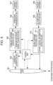
- Fig. 6 is a schematic diagram that illustrates one example of a block configuration of the terminal device 1 according to this embodiment.
- the terminal device 1 has a receive antenna (terminal receive antenna) 601, an OFDM signal reception unit (downlink reception unit) 602, a downlink subframe processing unit 603, a transport block extraction unit (data extraction unit) 605, a control unit (terminal control unit) 606, a higher layer (higher layer control information acquisition unit) 607, a channel state measurement unit (CSI generation unit) 608, an uplink subframe generation unit 609, SC-FDMA signal transmission units (UCI transmission units) 611 and 612, and transmit antennas (terminal transmit antennas) 613 and 614.
- the downlink subframe processing unit 603 has a downlink reference signal extraction unit 604.
- the uplink subframe generation unit 609 has an uplink control information generation unit (UCI generation unit) 610.
- UCI generation unit uplink control information generation unit
- the control unit 502 retains a modulation and coding scheme (MCS) that indicates the modulation scheme, the coding rate, and so forth in the downlink, downlink resource assignment that indicates the RB used for data transmission, and information used for controlling a HARQ (redundancy version, HARQ process number, and new data index) and, based on those, controls the codeword generation unit 503 and the downlink subframe generation unit 504.
- MCS modulation and coding scheme
- HARQ redundancy version, HARQ process number, and new data index
- the downlink data (also referred to as downlink transport block) transmitted from the higher layer 501 undergo processes such as error correction coding and a rate matching process in the codeword generation unit 503 and under control by the control unit 502, and codewords are thereby generated.
- a maximum of two codewords are simultaneously transmitted in one subframe in one cell.
- the downlink subframe generation unit 504 generates the downlink subframe in accordance with an instruction of the control unit 502.
- the codeword generated in the codeword generation unit 503 is converted into a modulation symbol sequence by a modulation process such as phase shift keying (PSK) modulation or quadrature amplitude modulation (QAM).
- PSK phase shift keying
- QAM quadrature amplitude modulation
- the modulation symbol sequence is mapped on the REs in a portion of the RBs, and the downlink subframe for respective antenna ports are generated by a precoding process.
- a transmission data sequence transmitted from the higher layer 501 contains the higher layer control information, which is control information in the higher layer (for example, dedicated (individual) radio resource control (RRC) signaling).
- RRC radio resource control
- the downlink reference signal generation unit 505 generates the downlink reference signal.
- the downlink subframe generation unit 504 maps the downlink reference signal on the RE in the downlink subframe in accordance with an instruction of the control unit 502.
- the downlink subframe generated by the downlink subframe generation unit 504 is modulated into OFDM signals in the OFDM signal transmission unit 506 and transmitted via the transmit antenna 507.
- the configuration is exemplified in which one OFDM signal transmission unit 506 and one transmit antenna 507 are provided.
- the downlink subframe generation unit 504 may have ability to generate the downlink control channels in the physical layer such as the PDCCH and EPDCCH and to map those on the REs in the downlink subframe.
- Each of the plural base station devices (the base station device 2-1 and the base station device 2-2) transmits an individual downlink subframe.
- the terminal device 1 receives the OFDM signals by the OFDM signal reception unit 602 via the receive antenna 601 and conducts an OFDM demodulation process.
- the downlink subframe processing unit 603 first detects the downlink control channels in the physical layer such as the PDCCH or EPDCCH. More specifically, the downlink subframe processing unit 603 performs decoding while assuming that the PDCCH or EPDCCH is transmitted in the region to which the PDCCH or EPDCCH may be allocated and checks cyclic redundancy check (CRS) bits that are in advance added (blind decoding). That is, the downlink subframe processing unit 603 monitors the PDCCH and EPDCCH.
- CRS cyclic redundancy check
- the downlink subframe processing unit 603 recognizes that the PDCCH or EPDCCH is detected and extracts the PDSCH by using the control information contained in the detected PDCCH or EPDCCH.
- a terminal-specific identifier that is alone assigned to one terminal such as a cell-radio network temporary identifier (C-RNTI) or a semi persistent scheduling-C-RNTI (SPS-C-RNTI) or a temporary C-RNTI
- the downlink subframe processing unit 603 recognizes that the PDCCH or EPDCCH is detected and extracts the PDSCH by using the control information contained in the detected PDCCH or EPDCCH.
- the control unit 606 retains the MCS that indicates the modulation scheme, the coding rate, and so forth in the downlink based on the control information, the downlink resource assignment that indicates the RB used for downlink data transmission, and the information used for controlling the HARQ and, based on those, controls the downlink subframe processing unit 603, the transport block extraction unit 605, and so forth. More specifically, the control unit 606 performs control such that an RE demapping process, a demodulation process, and so forth that correspond to an RE mapping process and the modulation process in the downlink subframe generation unit 504 are performed.
- the PDSCH extracted from the received downlink subframe is transmitted to the transport block extraction unit 605.
- the downlink reference signal extraction unit 604 in the downlink subframe processing unit 603 extracts the downlink reference signal from the downlink subframe.
- the transport block extraction unit 605 conducts the rate matching process, error correction decoding, and so forth that correspond to the rate matching process and the error correction coding in the codeword generation unit 503, extracts the transport block, and transmits the transport block to the higher layer 607.
- the transport block contains the higher layer control information, and the higher layer 607 notifies the control unit 606 of a necessary physical parameter based on the higher layer control information.
- Each of the plural base station devices 2 (the base station device 2-1 and the base station device 2-2) transmits the individual downlink subframe.
- the terminal device 1 may perform the above-described processes for the downlink subframe of each of the plural base station device 2.
- the terminal device 1 may or may not recognize that the plural downlink subframes are transmitted from the plural base station devices 2.
- the terminal device 1 may simply recognize that the plural downlink subframes are transmitted in plural cells.
- the terminal device 1 transmits the downlink reference signal extracted by the downlink reference signal extraction unit 604 to the channel state measurement unit 608, measures the channel state and/or interference in the channel state measurement unit 608, and further calculates the CSI based on the measured channel state and/or interference under instructions of the control unit 606.
- the terminal device 1 performs those processes for the downlink subframe of each of the plural cells.
- the uplink control information generation unit 610 generates the PUCCH that contains the calculated CSI.
- the uplink subframe generation unit 609 maps the PUSCH that contains uplink data transmitted from the higher layer 607 and the PUCCH generated in the uplink control information generation unit 610 on the RBs in the uplink subframe and thereby generates the uplink subframe.
- the uplink subframe that contains the PUCCH and PUCCH is generated for each connectivity group.
- the connectivity group will be described in detail below. Here, it is assumed that there are two connectivity groups and those correspond to the base station device 2-1 and the base station device 2-2.
- the SC-FDMA signal transmission unit 611 conducts SC-FDMA modulation for the uplink subframe in one connectivity group (for example, the uplink subframe transmitted to the base station device 2-1), generates SC-FDMA signals thereof, and transmits the uplink subframe via the transmit antenna 613.
- the SC-FDMA signal transmission unit 612 conducts the SC-FDMA modulation for the uplink subframe in the other connectivity group (for example, the uplink subframe transmitted to the base station device 2-2), generates SC-FDMA signals thereof, and transmits the uplink subframe via the transmit antenna 614. Further, the uplink subframes in two or more connectivity groups may simultaneously be transmitted by using one subframe.
- Each of the base station device 2-1 and the base station device 2-2 receives the uplink subframe in one connectivity group.
- the SC-FDMA signal reception unit 509 receives the SC-FDMA signals via the receive antenna 508, and an SC-FDMA demodulation process is conducted.
- the uplink subframe processing unit 510 extracts the RB on which the PUCCH is mapped in accordance with an instruction of the control unit 502, and the uplink control information extraction unit 511 extracts the CSI contained in the PUCCH.
- the extracted CSI is transmitted to the control unit 502.
- the CSI is used for control of downlink transmission parameters (MCS, downlink resource assignment, HARQ, and so forth) by the control unit 502.
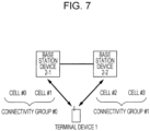
- Fig. 7 illustrates one example of the connectivity group.
- the base station device 2-1, the base station device 2-2, and the terminal device 1 perform communication in plural serving cells (cell #0, cell #1, cell #2, and cell #3).
- the cell #0 is the primary cell
- the cell #1, cell #2, and cell #3, which are the other cells, are the secondary cells.
- the four cells are covered (provided) by the base station device 2-1 and the base station device 2-2, which are actually two different base station devices.
- the cell #0 and cell #1 are covered by the base station device 2-1, and the cell #2 and cell #3 are covered by the base station device 2-2.
- the serving cells are categorized into plural groups, and each of the groups is referred to as connectivity group.
- the serving cells across low-speed backhaul may be categorized into a different group, and the serving cells that may use high-speed backhaul or the serving cells that do not have to use the backhaul because those are provided by the same device may be categorized into the same group.
- the serving cells of the connectivity group to which the primary cell belongs may be referred to as master cell, and the serving cells of the other connectivity groups may be referred to as assistant cell.
- one serving cell in the connectivity group (for example, the serving cell whose cell index is smallest in the connectivity group) may be referred to as lead cell.
- the serving cells in the connectivity have component carriers with different carrier frequencies.
- the serving cells in different connectivity groups may have component carriers with mutually different carrier frequencies or may have component carriers with the same carrier frequency (the same carrier frequency may be configured).
- the carrier frequencies of the downlink component carrier and the uplink component carrier of the cell #1 are different from those of the cell #0.
- the carrier frequencies of the downlink component carrier and the uplink component carrier that the cell #2 includes may be different from or the same as those of the cell #0.
- the SR is preferably transmitted for each of the connectivity groups.
- the terminal device 1 and the base station device 2 may use any of the following methods (1) to (5), for example, as a method of grouping the serving cells.
- the connectivity group may be configured by a method other than (1) to (5).
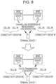
- Fig. 8 illustrates one example of generation and report of the CSI in the connectivity groups of the terminal device 1.
- the base station device 2-1 and/or the base station device 2-2 configure parameters of the downlink reference signals in the serving cells for the terminal device 1 and transmit the downlink reference signals in the serving cells provided by the respective base station devices 2-1 and 2-2.
- the terminal device 1 receives the downlink reference signals in the serving cells and performs channel measurement and/or interference measurement.
- the downlink reference signal described here may include the CRS, a non-zero-power CSI-RS, and a zero-power CSI-RS.
- the terminal device 1 preferably performs the channel measurement by using the non-zero-power CSI-RS and performs the interference measurement by using the zero-power CSI-RS.
- the terminal device 1 calculates the RI that indicates a preferable rank, the PMI that indicates a preferable precoding matrix, and the CQI as the largest index that corresponds to the modulation scheme and the coding rate which satisfy desired quality (for example, where the transport block error rate does not exceed 0.1) with respect to a reference resource.
- the terminal device 1 reports the CSI.
- the CSI of the serving cells that belong to the connectivity group is reported by using an uplink resource (PUCCH resource or PUSCH resource) in the cell of the concerned connectivity group.
- the CSI of the cell #0 and the CSI of the cell #1 are transmitted by using the PUCCH of the cell #0, which is the lead cell and also the primary cell of connectivity group #0.
- the CSI of the cell #0 and the CSI of the cell #1 are transmitted by using the PUSCH of any one of the cells that belong to the connectivity group #0.
- the CSI of the cell #2 and the CSI of the cell #3 are transmitted by using the PUCCH of the cell #2, which is the lead cell of connectivity group #1. Further, in a certain subframe, the CSI of the cell #2 and the CSI of the cell #3 are transmitted by using the PUSCH of any one of the cells that belong to the connectivity group #1. That is, each of the lead cells may provide a portion of the functions of the primary cell (for example, transmission of the CSI by using the PUCCH) in the carrier aggregation in related art.
- the CSI reports about the serving cells of the connectivity groups exhibit similar behavior to the CSI reports about the serving cells in the carrier aggregation.
- a PUCCH resource for periodic CSI of the serving cells that belong to a certain connectivity group is configured for the lead cell of the same connectivity group.
- the base station device 1 transmits information for configuring the PUCCH resource for the periodic CSI in the lead cell to the terminal device 1.
- the terminal device 1 receives the information for configuring the PUCCH resource for the periodic CSI in the lead cell
- the terminal device 1 performs a report of the periodic CSI by using the PUCCH resource.
- the base station device 1 does not transmit information for configuring the PUCCH resource for the periodic CSI in the cell other than the lead cell to the terminal device 1.
- the terminal device 1 receives the information for configuring the PUCCH resource for the periodic CSI in the cell other than the lead cell, the terminal device 1 performs error handling and does not perform the report of the periodic CSI by using the PUCCH resource.
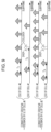
- Fig. 9 illustrates one example of periodic CSI reports.
- the periodic CSI is periodically fed back from the terminal device 1 to the base station device 2 in the subframe in the period that is configured by the dedicated RRC signaling. Further, the periodic CSI is usually transmitted by using the PUCCH. Parameters (the period of the subframe, the offset between a reference subframe and a starting subframe, and a report mode) of the periodic CSI may individually be configured for each of the serving cells. An index of the PUCCH resource for the periodic CSI may be configured for each of the connectivity groups.
- the periods of the cells #0, #1, #2, and #3 are configured as T 1 , T 2 , T 3 , and T 4 , respectively.
- the terminal device 1 performs uplink transmission of the periodic CSI of the cell #0 by the subframe of a T 1 period and performs uplink transmission of the periodic CSI of the cell #1 by the subframe of a T 2 period, by using the PUCCH resource of the cell #0, which is the lead cell and also the primary cell of the connectivity group #0.
- the terminal device 1 performs uplink transmission of the periodic CSI of the cell #2 by the subframe of a T 3 period and performs uplink transmission of the periodic CSI of the cell #3 by the subframe of a T 4 period, by using the PUCCH resource of the cell #2, which is the lead cell of the connectivity group #1.
- the periodic CSI reports collide with each other between plural servings in one connectivity group (a case where plural periodic CSI reports occur in one subframe), only one periodic CSI report is transmitted, and the other periodic CSI report is dropped (not transmitted).
- the terminal device 1 may use methods that will next be described. That is, in each of the connectivity groups, the periodic CSI report is dropped in accordance with the following (A1) to (A12). Preferably, determinations are performed in ascending order from (A1), and processes that match with conditions are sequentially performed.
- the terminal device 1 If the terminal device 1 is configured with more than one serving cell, the terminal device 1 transmits the periodic CSI report of only one serving cell in any given subframe. For a given subframe, in a case of the collision of the periodic CSI report with the PUCCH report type 3, 5, 6, or 2a of one serving cell with the periodic CSI report with the PUCCH report type 1, 1a, 2, 2b, 2c, or 4 of another serving cell, the latter periodic CSI report (the PUCCH report type 1, 1a, 2, 2b, 2c, or 4) has low priority and is dropped.
- the latter periodic CSI report with the PUCCH report type 1 or 1 a has low priority and is dropped.
- the periodic CSI report of a certain PUCCH report type has to be transmitted by a PUCCH format 2, 2a, or 2b.
- the terminal device 1 If the terminal device 1 is not configured for simultaneous the PUSCH and PUCCH transmission or, if the terminal device 1 is configured for simultaneous the PUSCH and PUCCH transmission and not transmitting the PUSCH, in a case of collision between the periodic CSI and a positive SR in the same subframe, the CSI is dropped. However, in a case where the terminal device 1 is configured to simultaneously transmit the HARQ-ACK and the periodic CSI by using a PUCCH format 3 and the HARQ-ACK, the periodic CSI, and a positive or negative SR collide with each other in the same subframe, the HARQ-ACK, the periodic CSI, and the positive or negative SR are simultaneously transmitted by the PUCCH format 3, and the CSI is not dropped.
- the PUCCH report types 1, 1a, 2, 2a, 2b, 2c, 3, 4, 5, and 6 are used for feedback of the sub-band CQI in the sub-band selected by the terminal device 1, the sub-band CQI and the second PMI, the wideband CQI and PMI, the wideband PMI, the wideband CQI and PMI, the wideband CQI and PMI, the RI, the wideband CQI, the RI and the wideband PMI, and the RI and the PTI, respectively.
- the transmission modes 1 to 10 are downlink transmission modes and correspond to single antenna port transmission, transmission diversity transmission, high-delay cyclic delay diversity (CCD) transmission, closed-loop spatial multiplexing transmission, multi-user multiple input multiple output (MU-MIMO) transmission, single layer closed-loop spatial multiplexing transmission, the single antenna port transmission, up to 2-layer transmission, up to 8-layer transmission, and the up to 8-layer transmission (the up to 8-layer transmission and/or coordinated multipoint transmission), respectively.
- one CSI process may be configured for one serving cell for which the transmission modes 1 to 9 are configured
- one or more CSI processes may be configured for one serving cell for which the transmission mode 10 is configured
- the periodic CSI report is performed for each of the CSI processes.
- the CSI processes correspond to transmission points for coordinated multiple point (CoMP) transmission, and different CSI process identifiers are assigned to the CSI processes.
- the PUCCH format 2, 2a, or 2b is a format of the PUCCH for feeding back the periodic CSI.
- the PUCCH format 3 is a format of the PUCCH for feeding back the HARQ-ACK.
- the terminal device 1 may use the following methods (B1) to (B12). Preferably, determinations are performed in ascending order from (B 1), and processes that match with conditions are sequentially performed.
- the terminal device 1 transmits the periodic CSI report of only one serving cell of each of the connectivity groups in an arbitrary subframe.
- the latter periodic CSI report (the PUCCH report type 1, 1a, 2, 2b, 2c, or 4) has low priority and is dropped.
- the latter periodic CSI report of the PUCCH report type 1 or 1a has low priority and is dropped.
- the CSI is dropped in a case where the CSI and the positive SR in the same connectivity group collide with each other in the same subframe.
- the terminal device 1 is configured to simultaneously transmit the HARQ-ACK and the periodic CSI by using the PUCCH format 3 in the connectivity group and the HARQ-ACK, the periodic CSI, and the positive or negative SR to the connectivity group collide with each other in the same subframe, the HARQ-ACK, the periodic CSI, and the positive or negative SR to the connectivity group are simultaneously transmitted by the PUCCH format 3 in the connectivity group, and the periodic CSI is not dropped.
- the dropping is performed in accordance with a prescribed rule that is separately defined. Rules described in (C1) or (C2) may be used as the prescribed rule.
- (C1) In a case where the periodic CSI report collides with the HARQ-ACK in the same subframe by which the PUSCH is not transmitted with respect to the terminal device 1 for which one serving cell is configured and the PUCCH format 3 is not configured, if a first parameter that is configured in the higher layer and is about simultaneous transmission of the HARQ-ACK and periodic CQI is set to true, the periodic CSI report is multiplexed with the HARQ-ACK in the PUCCH. If the first parameter is not set to true, the periodic CSI report is dropped.
- the periodic CSI report collides with the HARQ-ACK in the same subframe by which the PUSCH is not transmitted with respect to the terminal device 1 for which more than one serving cell is configured, if the first parameter that is configured in the higher layer and is about simultaneous transmission of the HARQ-ACK and periodic CQI is set to true and the HARQ-ACK corresponds to PDSCH transmission only in the primary cell or the PDCCH or EPDCCH that indicates SPS release, the periodic CSI report is multiplexed with the HARQ-ACK in the PUCCH by using the PUCCH format 2, 2a, or 2b.
- the PUCCH resource is decided in a procedure related to the PUCCH format 3, and the number of the total bits in the subframe that corresponds to the HARQ-ACK, the SR, and the periodic CSI thereof is not larger than 22 in a usual case or a spatially bundled case, the periodic CSI report is multiplexed with the HARQ-ACK in the PUCCH by using the PUCCH format 3. Otherwise, the periodic CSI is dropped.
- the terminal device 1 may use methods that will next be described. That is, in each of the connectivity groups, the terminal device 1 decides the uplink resource (PUCCH resource or PUSCH resource) for transmitting the periodic CSI report and/or the HARQ-ACK in accordance with any of the following (D1) to (D6).
- the uplink control information for a certain connectivity group contains only the periodic CSI in a subframe n, and the PUSCH is not transmitted in the connectivity group, the uplink control information is transmitted by the PUCCH of the lead cell in the connectivity group.
- the uplink control information for a certain connectivity group contains the periodic CSI and/or the HARQ-ACK in the subframe n, and the PUSCH is transmitted by the lead cell in the connectivity group, the uplink control information is transmitted by the PUSCH of the lead cell in the connectivity group.
- the uplink control information for a certain connectivity group contains the periodic CSI and/or the HARQ-ACK in the subframe n
- the PUSCH is not transmitted by the lead cell in the connectivity group
- the PUSCH is transmitted by at least one secondary cell other than the lead cell in the connectivity group
- the uplink control information is transmitted by the PUSCH of the secondary cell with the smallest cell index in the connectivity group.
- the uplink control information for a certain connectivity group contains the periodic CSI and the HARQ-ACK in the subframe n, and the PUSCH is transmitted by the lead cell in the connectivity group, the HARQ-ACK is transmitted by the PUCCH of the lead cell in the connectivity group, and the periodic CSI is transmitted by the PUSCH of the lead cell in the connectivity group.
- the uplink control information for a certain connectivity group contains the periodic CSI and the HARQ-ACK in the subframe n
- the PUSCH is not transmitted by the lead cell in the connectivity group
- the PUSCH is transmitted by at least another secondary cell in the same connectivity group
- the HARQ-ACK is transmitted by the PUCCH of the lead cell in the connectivity group
- the periodic CSI is transmitted by the PUSCH of the secondary cell with the smallest secondary cell index in the connectivity group.
- the terminal device 1 configures the connectivity identifier for each of the serving cells in the higher layer control information acquisition unit and calculates the periodic channel state information of each of the serving cells in the channel state information generation unit.
- the terminal device 1 In one subframe, in a case where the reports of the periodic channel state information of the serving cells with the connectivity identifiers of the same value collide with each other, pieces of the period channel state information other than one piece thereof are dropped, and the uplink control information is generated in the uplink control information generation unit.
- the uplink subframe that contains the uplink control information is transmitted in the uplink control information transmission unit.
- At least one of the base station device 2-1 and the base station device 2-2 configures values that correspond to the plural base station devices as the connectivity identifiers of the serving cells (for example, a first value for the serving cells of the base station device 2-1, a second value for the serving cells of the base station device 2-2, or the like) in the higher layer control information notification unit.
- each of the base station device 2-1 and the base station device 2-1 receives the uplink subframe in the uplink control information reception unit and extracts the uplink control information that contains only one piece of periodic channel state information among colliding pieces of periodic channel state information in the uplink control information extraction unit in a case where the reports of the periodic channel state information of two or more serving cells with the connectivity identifier value that corresponds to the first base station device collide with each other.
- the CSI of the serving cells in the connectivity groups is preferably transmitted and received by the uplink subframes of the respective lead cells of the connectivity groups.
- both of or only one of the base station device 2-1 and the base station device 2-2 may include the functions of the higher layer control information notification unit. Only one of the base station device 2-1 and the base station device 2-2 including the functions means that the higher layer control information is transmitted by either one of the base station device 2-1 and the base station device 2-2 in the dual connectivity but does not mean employment of the configuration that the base station device 2-1 or the base station device 2-2 does not have the higher layer control information notification unit itself.
- the base station device 2-1 and the base station device 2-2 have a backhaul transmission reception mechanism.
- the base station device 2-2 performs configuration related to the serving cells provided by the base station device 2-1 (which includes connectivity group configuration of those serving cells), the base station device 2-1 transmits the information that indicates the configuration to the base station device 2-2 via the backhaul, and the base station device 2-2 performs configuration (configuration in the base station device 2-2 or signaling to the terminal device 1) based on the information received via the backhaul.
- the base station device 2-1 performs configuration related to the serving cells provided by the base station device 2-2
- the base station device 2-2 transmits the information that indicates the configuration to the base station device 2-1 via the backhaul, and the base station device 2-1 performs configuration (configuration in the base station device 2-1 or signaling to the terminal device 1) based on the information received via the backhaul.
- a portion of the functions of the higher layer control information notification unit may be provided by the base station device 2-2, and the other functions may be provided by the base station device 2-1.
- the base station device 2-1 may be referred to as master base station device
- the base station device 2-2 may be referred to as assisting base station device.
- the assisting base station device may provide configuration related to the serving cells provided by the assisting base station device (which includes connectivity group configuration of those serving cells) to the terminal device 1.
- the master base station device may provide configuration related to the serving cells provided by the master base station device (which includes connectivity group configuration of those serving cells) to the terminal device 1.
- the terminal device 1 may recognize that communication is performed only with the base station device 2-1. That is, the higher layer control information acquisition unit may acquire the higher layer control information that is notified from the base station device 2-1 and the base station device 2-2 while assuming that the higher layer control information is notified from the base station device 2-1. Alternatively, the terminal device 1 may recognize that communication is performed with two base station devices, which are the base station device 2-1 and the base station device 2-1. That is, the higher layer control information acquisition unit may acquire the higher layer control information that is notified from the base station device 2-1 and the higher layer control information that is notified from the base station device 2-2 and may combine (merge) those together.
- each of the base station devices 2 may directly receive a desired periodic CSI report from the terminal device 1 not via the other base station device 2.
- scheduling may be performed by using a timely periodic CSI report.
- the aperiodic CSI report is indicated by using a CSI request field in the uplink grant transmitted by the PDCCH or EPDCCH and is transmitted by the PUSCH. More specifically, the base station device 2-1 or the base station device 2-2 first configures n kinds (n is a natural number) of serving cell combinations (or CSI process combinations) for the terminal device 1 by using the dedicated RRC signaling.
- the CSI request field may express n + 2 kinds of states.
- the states represent not feeding back the aperiodic CSI report, feeding back the CSI report in the serving cell assigned by the uplink grant (or in the CSI process in the serving cell assigned by the uplink grant), and feeding back the CSI report in n kinds (n is a natural number) of combinations of the serving cells (or combinations of the CSI processes) that are in advance configured.
- the base station device 2-1 or the base station device 2-2 configures the value of the CSI request field based on a desired CSI report, and the terminal device 1 determines which CSI report is performed based on the value of the CSI request field and performs the CSI report.
- the base station device 2-1 or the base station device 2-2 receives a desired CSI report.
- n kinds (n is a natural number) of serving cell combinations (or CSI process combinations) are configured for each of the connectivity group.
- the base station device 2-1 or the base station device 2-2 configures n kinds (n is a natural number) of combinations of the serving cells in the connectivity group #0 (or combinations of the CSI processes in the connectivity group #0) and n kinds (n is a natural number) of combinations of the serving cells in the connectivity group #1 (or combinations of the CSI processes in the connectivity group #0) for the terminal device 1.
- the base station device 2-1 or the base station device 2-2 configures the value of the CSI request field based on a desired CSI report.
- the terminal device 1 determines to which connectivity group the serving cell, to which the PUSCH resource is assigned by the uplink grant for requesting the aperiodic CSI report, belongs, determines which CSI report is performed by using n kinds (n is a natural number) of serving cell combinations (or CSI process combinations) that correspond to the connectivity group to which the serving cell, to which the PUSCH resource is assigned by the uplink grant for requesting the aperiodic CSI report, belongs, and performs the aperiodic CSI report by the PUSCH assigned by the uplink grant for requesting the aperiodic CSI report.
- the base station device 2-1 or the base station device 2-2 receives a desired CSI report.
- n is a natural number of serving cell combinations (or CSI process combinations)
- Each set of n kinds (n is a natural number) of serving cell combinations (or CSI process combinations) is limited to the combination of the serving cells that belong to any connectivity group (or the CSI processes of the serving cells that belong to the connectivity group).
- the base station device 2-1 or the base station device 2-2 configures the value of the CSI request field based on a desired aperiodic CSI report, and the terminal device 1 determines which aperiodic CSI report is performed based on the value of the CSI request field and performs the aperiodic CSI report.
- the base station device 2-1 or the base station device 2-2 receives a desired aperiodic CSI report.
- each of the base station devices 2 may directly receive a desired aperiodic CSI report from the terminal device 1 not via the other base station device 2.
- each PUSCH contains only the aperiodic CSI report of the serving cell that belongs to one connectivity group (or the CSI process of the serving cell that belongs to the connectivity group), and the aperiodic CSI report that is independent from the configuration of the other base station device 2 may thus be received from the terminal device 1.
- scheduling may be performed by using a timely aperiodic CSI report.
- a second embodiment of the present invention will hereinafter be described. In the description made below, only components that are different from the first embodiment will be focused on and described. That is, as for other than those, the techniques described in the first embodiment may be used.
- Fig. 10 is a schematic diagram that illustrates one example of the block configuration of the terminal device 1 according to this embodiment.
- the terminal device 1 has the receive antenna (terminal receive antenna) 601, the OFDM signal reception unit (downlink reception unit) 602, the downlink subframe processing unit 603, the transport block extraction unit (data extraction unit) 605, a control unit (terminal control unit) 1006, a higher layer (higher layer control information acquisition unit) 1007, the channel state measurement unit (CSI generation unit) 608, an uplink subframe generation unit 1009, an SC-FDMA signal transmission unit (UCI transmission unit) 1011, and a transmit antenna (terminal transmit antenna) 1013.
- the downlink subframe processing unit 603 has the downlink reference signal extraction unit 604.
- the uplink subframe generation unit 1009 has the uplink control information generation unit (UCI generation unit) 610.
- the blocks provided with the same reference numerals as the blocks in Fig. 6 are configured to have the same functions as the blocks in Fig. 6 .
- the terminal device 1 in this embodiment may transmit the PUCCH or PUSCH to only one connectivity group in one subframe.
- the base station device 2-1 or the base station device 2-2 configures which uplink subframes are the subframes for which connectivity groups, that is, configures the set of uplink subframes for each of the connectivity groups for the terminal device 1 by using the dedicated RRC signaling or common RRC signaling.
- the higher layer 1007 transmits parameters based on the configuration to the control unit 1006.
- the control unit 1006 instructs the uplink subframe generation unit 1009 that the uplink subframe for which connectivity group is generated. Further, the control unit 1006 instructs the SC-FDMA signal transmission unit 1011 that transmission is performed by the uplink component carrier in the serving cell for which connectivity group.
- the uplink subframe generation unit 1009 generates the uplink subframe for any of the connectivity groups under the instructions of the control unit 1006.
- the SC-FDMA signal transmission unit 1011 transmits SC-FDMA signals at the carrier frequency for the uplink component carrier in the serving cell of any of the connectivity groups under the instructions of the control unit 1006.
- the transmit antenna 1013 may transmit signals at the carrier frequency for the uplink component carrier in the serving cell of any of the connectivity groups.
- Fig. 11 illustrates one example of the periodic CSI reports.
- the parameters (the period of the subframe, the offset between a reference subframe and a starting subframe, and the report mode) of the periodic CSI may individually be configured for each of the serving cells.
- the index of the PUCCH resource for the periodic CSI may be configured for each of the connectivity groups.
- the periods of the cells #0, #1, #2, and #3 are configured as T 1 , T 2 , T 3 , and T 4 , respectively.
- uplink transmission of the periodic CSI of the cell #0 is performed by the subframe of the T 1 period
- uplink transmission of the periodic CSI of the cell #1 is performed by the subframe of the T 2 period
- uplink transmission of the periodic CSI of the cell #2 is performed by the subframe of the T 3 period
- uplink transmission of the periodic CSI of the cell #3 is performed by the subframe of the T 4 period.
- only the periodic CSI report in the serving in one connectivity group (or in the CSI process of the serving cell in one connectivity group) is transmitted, and the periodic CSI report of the other connectivity group is dropped (not transmitted).
- the following methods (E1) and (E2) may be used.
- the base station device 2-1 or the base station device 2-2 configures an uplink subframe set that corresponds to each of the connectivity groups (for example, an uplink subframe set #0 that corresponds to the connectivity group #0 or an uplink subframe set #1 that corresponds to the connectivity group #1) for the terminal device 1.
- the terminal device 1 determines which uplink subframe set the subframe for performing the periodic CSI report is included in and drops the periodic CSI report in a case where the connectivity group of the periodic CSI report does not match with the connectivity group of the subframe (unless the connectivity groups match with each other).
- the periodic CSI report is transmitted.
- the base station device 2-1 or the base station device 2-2 does not extract the periodic CSI report in a case where the periodic CSI report is dropped but extracts the periodic CSI report in a case where the periodic CSI report is transmitted.
- the base station device 2-1 or the base station device 2-2 transmits the uplink grant for instructing on PUSCH transmission by the serving cell of any of the connectivity groups to the terminal device 1.
- the terminal device 1 drops the periodic CSI report.
- the periodic CSI report is transmitted by using the PUCCH or PUSCH.
- the base station device 2-1 or the base station device 2-2 does not extract the periodic CSI report in a case where the periodic CSI report is dropped but extracts the periodic CSI report in a case where the periodic CSI report is transmitted.
- the terminal device 1 may drop the aperiodic CSI report unless the connectivity group of the periodic CSI report matches with the connectivity group of the subframe.
- the terminal device 1 may transmit only the aperiodic CSI report in the serving cell except the serving cells that do not match.
- the terminal device 1 may drop all the aperiodic CSI reports that are indicated by the CSI request field. Alternatively, the terminal device 1 may avoid assuming reception of the CSI request in which the connectivity group of the serving cell in the combination does not match with the connectivity group of the subframe for the aperiodic CSI report. In this case, the base station device 2-1 or the base station device 2-2 has to indicate the combination that includes only the serving cell which matches with the connectivity group of the subframe for the aperiodic CSI report by using the CSI request field. A case where the CSI process of the serving cell is used instead of the serving cell is similar.
- each of the base station devices 2 may directly receive a desired CSI report from the terminal device 1 not via the other base station device 2.
- scheduling may be performed by using a timely CSI report.
- embodiments are not limited to this.
- the connectivity identifier is configured for the downlink signals or the uplink signals.
- the downlink signals and the uplink signals may individually be grouped.
- the connectivity identifiers are individually configured for the downlink signals and the uplink signals.
- the downlink component carriers may be grouped, or the uplink component carriers may be grouped. In this case, the connectivity identifiers are individually configured for the component carriers.
- the set of the serving cells provided by the same base station device (transmission point) does not necessarily have to be specified by the connectivity group.
- the set of the serving cells may be specified by using the connectivity identifier or the cell index.
- the connectivity group in the above embodiments may be, in other words, the set of the serving cells that have the same connectivity identifier.
- the connectivity group in the above embodiments may be, in other words, the set of the serving cells with the cell index of a prescribed value (or in a prescribed range).
- the primary cell in the above embodiments may also be referred to as master cell
- the lead cell in the above embodiments may also be referred to as primary cell.
- a program that operates in the base station device 2-1 or the base station device 2-2 and the terminal device 1 according to the present invention may be a program that controls a central processing unit (CPU) or the like so that functions of the above embodiments according to the present invention are realized (a program that allows a computer to function).
- CPU central processing unit
- information that is dealt with by those devices is temporarily accumulated in a random access memory (RAM) during processing thereof and thereafter stored in various kinds of read only memories (ROM) such as flash ROMs or hard disk drives (HDD). The information is read out, corrected, and written by the CPU as needed.
- a portion of the terminal device 1, the base station device 2-1, or the base station device 2-2 in the above-described embodiments may be realized by a computer.
- a program for realizing the control functions is recorded in a computer-readable recording medium, the program that is recorded in the recording medium is read and executed by a computer system, and the control functions may thereby be realized.
- the "computer system” herein is a computer system that is built in the terminal device 1, the base station device 2-1, or the base station device 2-2 and includes an OS and hardware such as peripheral apparatuses.
- "computer-readable recording media” are portable media such as flexible disks, magneto-optical disks, ROMs, and CD-ROMs and storage devices such as hard disks that are built in the computer system.
- the "computer readable recording media” may include elements that dynamically retain the program for a short period of time like communication wires in a case where the program is transmitted via a network such as the Internet and a communication line such as a telephone line and elements that retain the program for a certain period of time such as volatile memories in the computer systems that are servers or clients in the above case.
- the program may realize a portion of the above-described functions and may further be realized in combination with a program that has the above-described functions already recorded in the computer system.
- the base station device 2-1 or the base station device 2-2 in the above-described embodiments may be realized as an assembly (device group) that is configured with plural devices.
- Each of the devices that configure the device group may include the function or a portion of or whole the function block of the base station device 2-1 or the base station device 2-2 according to the above-described embodiments. It is sufficient that the device group has the general functions or the general function blocks of the base station device 2-1 or the base station device 2-2.
- the terminal device 1 according to the above-described embodiments is capable of communicating with the base station device as an assembly.
- the base station device 2-1 or the base station device 2-2 in the above-described embodiments may be the Evolved Universal Terrestrial Radio Access Network (EUTRAN). Further, the base station device 2-1 or the base station device 2-2 in the above-described embodiments may have a portion of or whole the function of a higher node with respect to an eNodeB.
- EUTRAN Evolved Universal Terrestrial Radio Access Network
- a portion or the whole of the terminal device 1, the base station device 2-1, or the base station device 2-2 in the above-described embodiments may typically be realized as an LSI that is an integrated circuit or may be realized as a chipset.
- Function blocks of the terminal device 1, the base station device 2-1, or the base station device 2-2 may individually be formed into chips, or a portion of or all the function blocks may be integrated into a chip.
- a method of forming the integrated circuit is not limited to an LSI, but the integrated circuit may be realized as a dedicated circuit or a general purpose processor. Further, in a case where a technology of forming an integrated circuit that replaces the LSI emerges as a result of progress of a semiconductor technology, an integrated circuit by the technology may be used.
- a cellular mobile station device has been described as one example of the terminal device or a communication device.
- the present invention is not limited to this but may also be applied to terminal devices or communication devices of stationary type or non-portable type electronic apparatuses for indoor or outdoor installation, for example, audio-visual apparatuses, kitchen apparatuses, cleaning or washing apparatuses, air-conditioning apparatuses, office apparatuses, vending machines, other household apparatuses, and so forth.
Landscapes
- Engineering & Computer Science (AREA)
- Signal Processing (AREA)
- Computer Networks & Wireless Communication (AREA)
- Mobile Radio Communication Systems (AREA)
Claims (2)
- Endgerätvorrichtung (1), die mit einer Master-Basisstationsvorrichtung (2-1) und einer zweiten Basisstationsvorrichtung (2-2) kommuniziert, wobei die Endgerätvorrichtung (1) eine erste Dienstzellengruppe, die eine Primärzelle enthält, und eine zweite Dienstzellengruppe verwendet, welche die Primärzelle nicht enthält, wobei die erste Dienstzellengruppe durch die Master-Basisstationsvorrichtung (2-1) bereitgestellt ist, die zweite Dienstzellengruppe durch die zweite Basisstationsvorrichtung (2-2) bereitgestellt ist, wobei die Endgerätvorrichtung (1) umfasst:eine Steuer- bzw. Regel- bzw. Kontrollinformationen-Erfassungseinheit (607) höherer Schicht, welche die zweite Dienstzellengruppe konfiguriert;eine Kanalzustandsinformationen-Generierungseinheit (608), die periodische Kanalzustandsinformationen jeder der Mehrzahl von Dienstzellen in der ersten Dienstzellengruppe und der zweiten Dienstzellengruppe berechnet;eine Uplink-Steuer- bzw. Regel- bzw. Kontrollinformationen-Generierungseinheit (610), dieerste Berichte und zweite Berichte generiert, wobei jeder der ersten Berichte die periodischen Kanalzustandsinformationen jeder einer ersten Mehrzahl von Dienstzellen in der ersten Dienstzellengruppe angibt, wobei jeder der zweiten Berichte die periodischen Kanalzustandsinformationen jeder einer zweiten Dienstzellen in der zweiten Dienstzellengruppe angibt,in einem Fall, in dem die ersten Berichte in einem Uplink-Subframe kollidieren, die ersten Berichte für alle der ersten Mehrzahl von Dienstzellen außer einer ersten Dienstzelle mit dem niedrigsten Zellenindex unter den Dienstzellenindizes der ersten Mehrzahl von Dienstzellen weglässt bzw. streicht bzw. löscht, in einem Fall, in dem die zweiten Berichte in einem Uplink-Subframe kollidieren, die zweiten Berichte für alle der zweiten Mehrzahl von Dienstzellen außer einer zweiten Dienstzelle mit dem niedrigsten Zellenindex unter den Dienstzellenindizes der zweiten Mehrzahl von Dienstzellen weglässt bzw. streicht bzw. löscht,erste Uplink-Steuer- bzw. Regel- bzw. Kontrollinformationen einschließlich des ersten Berichts der periodischen Kanalzustandsinformationen für die erste Dienstzelle und zweite Uplink-Steuer- bzw. Regel- bzw. Kontrollinformationen einschließlich des zweiten Berichts der periodischen Kanalzustandsinformationen für die zweite Dienstzelle generiert; undeine Uplink-Steuer- bzw. Regel- bzw. Kontrollinformationen-Übertragungseinheit (611, 612), die einen ersten Uplink-Subframe, der die ersten Uplink-Steuer- bzw. Regel- bzw. Kontrollinformationen enthält, an die Master-Basisstationsvorrichtung (2-1) und einen zweiten Uplink-Subframe, der die zweiten Uplink-Steuer- bzw. Regel- bzw. Kontrollinformationen enthält, an die zweite Basisstationsvorrichtung (2-2) überträgt, wobei der Zellenindex für die Primärzelle 0 ist, jeder der Werte von 1 bis 7 als der Zellenindex für jede der Dienstzellen konfiguriert ist, einschließlich der ersten Mehrzahl von Dienstzellen außer der Primärzelle und der zweiten Mehrzahl von Dienstzellen, durch die Master-Basisstationsvorrichtung (2-1) oder die zweite Basisstationsvorrichtung (2-2) unter Verwendung dedizierter Radio Resource Control,RRC,-Signalisierung.
- Endgerätvorrichtung (1) nach Anspruch 1, wobei die Steuer- bzw. Regel- bzw. Kontrollinformationen-Erfassungseinheit (607) höherer Schicht Steuer- bzw. Regel- bzw. Kontrollinformationen höherer Schicht erfasst und die zweite Dienstzellengruppe basierend auf den Steuer- bzw. Regel- bzw. Kontrollinformationen höherer Schicht konfiguriert.
Applications Claiming Priority (2)
| Application Number | Priority Date | Filing Date | Title |
|---|---|---|---|
| JP2013133401 | 2013-06-26 | ||
| PCT/JP2014/066712 WO2014208560A1 (ja) | 2013-06-26 | 2014-06-24 | 端末装置、基地局装置、および通信方法 |
Publications (3)
| Publication Number | Publication Date |
|---|---|
| EP3016459A1 EP3016459A1 (de) | 2016-05-04 |
| EP3016459A4 EP3016459A4 (de) | 2017-02-22 |
| EP3016459B1 true EP3016459B1 (de) | 2024-11-27 |
Family
ID=52141892
Family Applications (1)
| Application Number | Title | Priority Date | Filing Date |
|---|---|---|---|
| EP14816884.2A Active EP3016459B1 (de) | 2013-06-26 | 2014-06-24 | Endgerät |
Country Status (4)
| Country | Link |
|---|---|
| US (2) | US10021675B2 (de) |
| EP (1) | EP3016459B1 (de) |
| JP (1) | JP6524552B2 (de) |
| WO (1) | WO2014208560A1 (de) |
Families Citing this family (19)
| Publication number | Priority date | Publication date | Assignee | Title |
|---|---|---|---|---|
| KR20150020018A (ko) * | 2013-08-14 | 2015-02-25 | 삼성전자주식회사 | 이동 통신 시스템에서 복수의 캐리어를 이용하는 데이터 송수신 방법 및 장치 |
| KR102284453B1 (ko) * | 2014-01-29 | 2021-08-02 | 삼성전자 주식회사 | 셀룰러 이동 통신 시스템에서 상향링크 제어 정보 전송 방법 및 장치 |
| US20150327106A1 (en) * | 2014-05-06 | 2015-11-12 | Acer Incorporated | Method of Handling Channel Status Information and Related Communication Device |
| EP3178245B1 (de) * | 2014-08-06 | 2021-04-28 | LG Electronics Inc. | Verfahren zur unterstützung von amorphen zellen in einem drahtloskommunikationssystem |
| US9900074B2 (en) * | 2014-08-12 | 2018-02-20 | Qualcomm Incorporated | CSI request procedure in LTE/LTE-A with unlicensed spectrum |
| WO2016159229A1 (ja) * | 2015-04-02 | 2016-10-06 | 株式会社Nttドコモ | ユーザ端末、無線基地局及び無線通信方法 |
| JP6555833B2 (ja) | 2015-04-10 | 2019-08-07 | 華為技術有限公司Huawei Technologies Co.,Ltd. | Csiレポートの適用時間を決定するための方法および装置、ならびにデバイス |
| US11134479B2 (en) | 2015-05-22 | 2021-09-28 | Sharp Kabushiki Kaisha | Terminal device, integrated circuit, and communication method |
| DE102015009779B4 (de) * | 2015-07-27 | 2021-08-12 | Apple Inc. | Leistungsoptimierung für Kanalzustandsmeldungen in einem drahtlosen Kommunikationsnetz |
| EP3334204B1 (de) * | 2015-08-06 | 2025-06-04 | Sharp Kabushiki Kaisha | Endgerätevorrichtung, basisstationsvorrichtung, kommunikationsverfahren und integrierte schaltung |
| EP3364704B1 (de) * | 2015-11-03 | 2021-05-26 | Samsung Electronics Co., Ltd. | Verfahren und vorrichtung zum senden oder empfangen von steuerinformationen in einem drahtloskommunikationssystem |
| JP2019110360A (ja) * | 2016-04-28 | 2019-07-04 | シャープ株式会社 | 端末装置、基地局装置、通信方法、および、集積回路 |
| CN109479211B (zh) * | 2016-07-12 | 2023-04-18 | 株式会社Ntt都科摩 | 用户终端以及无线通信方法 |
| WO2018062908A1 (ko) * | 2016-09-29 | 2018-04-05 | 엘지전자 주식회사 | 무선 통신 시스템에서 상향링크 제어 정보를 송신하는 방법 및 이를 위한 장치 |
| SG11201911789XA (en) | 2017-09-14 | 2020-01-30 | Guangdong Oppo Mobile Telecommunications Corp Ltd | Method, device, storage medium, and system for determining time-domain resource |
| US11191001B2 (en) * | 2017-11-21 | 2021-11-30 | Ualcomm Incorporated | Handover schemes for millimeter wave (MMW) wireless communications |
| US11324015B2 (en) | 2017-11-22 | 2022-05-03 | Qualcomm Incorporated | Channel reporting for communication service priority types |
| EP4164154B1 (de) | 2018-10-12 | 2026-03-04 | Guangdong Oppo Mobile Telecommunications Corp., Ltd. | Verfahren, endgerät und netzwerkgerät zur wiederholten übertragung von informationen |
| US12063704B2 (en) * | 2021-09-21 | 2024-08-13 | Microsoft Technology Licensing, Llc | Accessory device communication utilizing host-synchronized transmission |
Family Cites Families (4)
| Publication number | Priority date | Publication date | Assignee | Title |
|---|---|---|---|---|
| US9930677B2 (en) * | 2010-12-07 | 2018-03-27 | Sharp Kabushiki Kaisha | Prioritizing multiple channel state information (CSI) reporting with carrier aggregation |
| JP2013005367A (ja) | 2011-06-21 | 2013-01-07 | Sharp Corp | 移動通信システム、基地局装置、移動局装置および通信方法 |
| US9509389B2 (en) * | 2011-11-01 | 2016-11-29 | Lg Electronics Inc. | Method and apparatus for transmitting channel state information in wireless communication system |
| JP5388244B1 (ja) * | 2012-08-06 | 2014-01-15 | 株式会社Nttドコモ | 移動局 |
-
2014
- 2014-06-24 EP EP14816884.2A patent/EP3016459B1/de active Active
- 2014-06-24 US US14/900,487 patent/US10021675B2/en active Active
- 2014-06-24 JP JP2015524062A patent/JP6524552B2/ja active Active
- 2014-06-24 WO PCT/JP2014/066712 patent/WO2014208560A1/ja not_active Ceased
-
2018
- 2018-06-29 US US16/023,882 patent/US20180324791A1/en not_active Abandoned
Also Published As
| Publication number | Publication date |
|---|---|
| JPWO2014208560A1 (ja) | 2017-02-23 |
| EP3016459A4 (de) | 2017-02-22 |
| WO2014208560A1 (ja) | 2014-12-31 |
| US20180324791A1 (en) | 2018-11-08 |
| US20160157223A1 (en) | 2016-06-02 |
| US10021675B2 (en) | 2018-07-10 |
| EP3016459A1 (de) | 2016-05-04 |
| JP6524552B2 (ja) | 2019-06-05 |
Similar Documents
| Publication | Publication Date | Title |
|---|---|---|
| US10021675B2 (en) | Terminal device, base station device, and communication method | |
| KR102933980B1 (ko) | 다수의 서비스 유형들이 있는 통신 시스템들에서의 스케줄링 | |
| JP2023052546A (ja) | 動的ul/dl構成を備えたlte tddのためのチャネル状態情報の構成、測定、及びレポートのための方法及び装置 | |
| JP6425662B2 (ja) | 端末装置、基地局装置および方法 | |
| US9456429B2 (en) | Terminal device, communication method, and integrated circuit | |
| JP6584958B2 (ja) | 端末装置、基地局装置および通信方法 | |
| EP2613600B1 (de) | Drahtloses kommunikationssystem, drahtlose basisstationsvorrichtung und mobilstationsvorrichtung | |
| JP6505019B2 (ja) | 端末装置、および端末装置における方法 | |
| CN110352578A (zh) | 下行链路控制信道的传输结构和格式 | |
| CN104521318B (zh) | 终端、基站、通信方法以及集成电路 | |
| KR102091607B1 (ko) | 상향링크 신호 전송 및 수신 방법, 및 이들을 위한 장치 | |
| EP2882255B1 (de) | Endgerät, basisstation, kommunikationsverfahren und integrierter schaltkreis | |
| WO2015137447A1 (ja) | 端末装置、基地局装置および通信方法 | |
| CN104685948A (zh) | 终端、通信方法以及集成电路 | |
| EP2983422B1 (de) | Endgerätevorrichtung, kommunikationsverfahren und integrierte schaltung | |
| WO2015166769A1 (ja) | 基地局装置及び送信方法 | |
| EP2983423B1 (de) | Endgerätevorrichtung, kommunikationsverfahren und integrierte schaltung | |
| EP3471475B1 (de) | Benutzerendgerät, funkbasisstation, funkkommunikationssystem und funkkommunikationsverfahren | |
| CN106664665A (zh) | 终端装置、基站装置以及通信方法 | |
| JP6306859B2 (ja) | 端末装置、基地局装置および通信方法 |
Legal Events
| Date | Code | Title | Description |
|---|---|---|---|
| PUAI | Public reference made under article 153(3) epc to a published international application that has entered the european phase |
Free format text: ORIGINAL CODE: 0009012 |
|
| 17P | Request for examination filed |
Effective date: 20151223 |
|
| AK | Designated contracting states |
Kind code of ref document: A1 Designated state(s): AL AT BE BG CH CY CZ DE DK EE ES FI FR GB GR HR HU IE IS IT LI LT LU LV MC MK MT NL NO PL PT RO RS SE SI SK SM TR |
|
| AX | Request for extension of the european patent |
Extension state: BA ME |
|
| DAX | Request for extension of the european patent (deleted) | ||
| A4 | Supplementary search report drawn up and despatched |
Effective date: 20170124 |
|
| RIC1 | Information provided on ipc code assigned before grant |
Ipc: H04W 16/32 20090101ALI20170118BHEP Ipc: H04L 5/00 20060101ALI20170118BHEP Ipc: H04W 24/10 20090101ALI20170118BHEP Ipc: H04W 72/04 20090101AFI20170118BHEP |
|
| STAA | Information on the status of an ep patent application or granted ep patent |
Free format text: STATUS: EXAMINATION IS IN PROGRESS |
|
| 17Q | First examination report despatched |
Effective date: 20190214 |
|
| GRAP | Despatch of communication of intention to grant a patent |
Free format text: ORIGINAL CODE: EPIDOSNIGR1 |
|
| STAA | Information on the status of an ep patent application or granted ep patent |
Free format text: STATUS: GRANT OF PATENT IS INTENDED |
|
| INTG | Intention to grant announced |
Effective date: 20240619 |
|
| GRAS | Grant fee paid |
Free format text: ORIGINAL CODE: EPIDOSNIGR3 |
|
| GRAA | (expected) grant |
Free format text: ORIGINAL CODE: 0009210 |
|
| STAA | Information on the status of an ep patent application or granted ep patent |
Free format text: STATUS: THE PATENT HAS BEEN GRANTED |
|
| AK | Designated contracting states |
Kind code of ref document: B1 Designated state(s): AL AT BE BG CH CY CZ DE DK EE ES FI FR GB GR HR HU IE IS IT LI LT LU LV MC MK MT NL NO PL PT RO RS SE SI SK SM TR |
|
| REG | Reference to a national code |
Ref country code: GB Ref legal event code: FG4D |
|
| REG | Reference to a national code |
Ref country code: CH Ref legal event code: EP |
|
| REG | Reference to a national code |
Ref country code: DE Ref legal event code: R096 Ref document number: 602014091237 Country of ref document: DE |
|
| REG | Reference to a national code |
Ref country code: IE Ref legal event code: FG4D |
|
| REG | Reference to a national code |
Ref country code: LT Ref legal event code: MG9D |
|
| REG | Reference to a national code |
Ref country code: NL Ref legal event code: MP Effective date: 20241127 |
|
| PG25 | Lapsed in a contracting state [announced via postgrant information from national office to epo] |
Ref country code: PT Free format text: LAPSE BECAUSE OF FAILURE TO SUBMIT A TRANSLATION OF THE DESCRIPTION OR TO PAY THE FEE WITHIN THE PRESCRIBED TIME-LIMIT Effective date: 20250327 Ref country code: IS Free format text: LAPSE BECAUSE OF FAILURE TO SUBMIT A TRANSLATION OF THE DESCRIPTION OR TO PAY THE FEE WITHIN THE PRESCRIBED TIME-LIMIT Effective date: 20250327 Ref country code: HR Free format text: LAPSE BECAUSE OF FAILURE TO SUBMIT A TRANSLATION OF THE DESCRIPTION OR TO PAY THE FEE WITHIN THE PRESCRIBED TIME-LIMIT Effective date: 20241127 |
|
| PG25 | Lapsed in a contracting state [announced via postgrant information from national office to epo] |
Ref country code: FI Free format text: LAPSE BECAUSE OF FAILURE TO SUBMIT A TRANSLATION OF THE DESCRIPTION OR TO PAY THE FEE WITHIN THE PRESCRIBED TIME-LIMIT Effective date: 20241127 Ref country code: NL Free format text: LAPSE BECAUSE OF FAILURE TO SUBMIT A TRANSLATION OF THE DESCRIPTION OR TO PAY THE FEE WITHIN THE PRESCRIBED TIME-LIMIT Effective date: 20241127 |
|
| REG | Reference to a national code |
Ref country code: AT Ref legal event code: MK05 Ref document number: 1746987 Country of ref document: AT Kind code of ref document: T Effective date: 20241127 |
|
| PG25 | Lapsed in a contracting state [announced via postgrant information from national office to epo] |
Ref country code: BG Free format text: LAPSE BECAUSE OF FAILURE TO SUBMIT A TRANSLATION OF THE DESCRIPTION OR TO PAY THE FEE WITHIN THE PRESCRIBED TIME-LIMIT Effective date: 20241127 |
|
| PG25 | Lapsed in a contracting state [announced via postgrant information from national office to epo] |
Ref country code: ES Free format text: LAPSE BECAUSE OF FAILURE TO SUBMIT A TRANSLATION OF THE DESCRIPTION OR TO PAY THE FEE WITHIN THE PRESCRIBED TIME-LIMIT Effective date: 20241127 |
|
| PG25 | Lapsed in a contracting state [announced via postgrant information from national office to epo] |
Ref country code: NO Free format text: LAPSE BECAUSE OF FAILURE TO SUBMIT A TRANSLATION OF THE DESCRIPTION OR TO PAY THE FEE WITHIN THE PRESCRIBED TIME-LIMIT Effective date: 20250227 |
|
| PG25 | Lapsed in a contracting state [announced via postgrant information from national office to epo] |
Ref country code: GR Free format text: LAPSE BECAUSE OF FAILURE TO SUBMIT A TRANSLATION OF THE DESCRIPTION OR TO PAY THE FEE WITHIN THE PRESCRIBED TIME-LIMIT Effective date: 20250228 Ref country code: LV Free format text: LAPSE BECAUSE OF FAILURE TO SUBMIT A TRANSLATION OF THE DESCRIPTION OR TO PAY THE FEE WITHIN THE PRESCRIBED TIME-LIMIT Effective date: 20241127 Ref country code: AT Free format text: LAPSE BECAUSE OF FAILURE TO SUBMIT A TRANSLATION OF THE DESCRIPTION OR TO PAY THE FEE WITHIN THE PRESCRIBED TIME-LIMIT Effective date: 20241127 |
|
| PG25 | Lapsed in a contracting state [announced via postgrant information from national office to epo] |
Ref country code: PL Free format text: LAPSE BECAUSE OF FAILURE TO SUBMIT A TRANSLATION OF THE DESCRIPTION OR TO PAY THE FEE WITHIN THE PRESCRIBED TIME-LIMIT Effective date: 20241127 |
|
| PG25 | Lapsed in a contracting state [announced via postgrant information from national office to epo] |
Ref country code: RS Free format text: LAPSE BECAUSE OF FAILURE TO SUBMIT A TRANSLATION OF THE DESCRIPTION OR TO PAY THE FEE WITHIN THE PRESCRIBED TIME-LIMIT Effective date: 20250227 |
|
| PG25 | Lapsed in a contracting state [announced via postgrant information from national office to epo] |
Ref country code: SM Free format text: LAPSE BECAUSE OF FAILURE TO SUBMIT A TRANSLATION OF THE DESCRIPTION OR TO PAY THE FEE WITHIN THE PRESCRIBED TIME-LIMIT Effective date: 20241127 |
|
| PG25 | Lapsed in a contracting state [announced via postgrant information from national office to epo] |
Ref country code: DK Free format text: LAPSE BECAUSE OF FAILURE TO SUBMIT A TRANSLATION OF THE DESCRIPTION OR TO PAY THE FEE WITHIN THE PRESCRIBED TIME-LIMIT Effective date: 20241127 |
|
| PG25 | Lapsed in a contracting state [announced via postgrant information from national office to epo] |
Ref country code: EE Free format text: LAPSE BECAUSE OF FAILURE TO SUBMIT A TRANSLATION OF THE DESCRIPTION OR TO PAY THE FEE WITHIN THE PRESCRIBED TIME-LIMIT Effective date: 20241127 |
|
| PG25 | Lapsed in a contracting state [announced via postgrant information from national office to epo] |
Ref country code: RO Free format text: LAPSE BECAUSE OF FAILURE TO SUBMIT A TRANSLATION OF THE DESCRIPTION OR TO PAY THE FEE WITHIN THE PRESCRIBED TIME-LIMIT Effective date: 20241127 |
|
| PG25 | Lapsed in a contracting state [announced via postgrant information from national office to epo] |
Ref country code: SK Free format text: LAPSE BECAUSE OF FAILURE TO SUBMIT A TRANSLATION OF THE DESCRIPTION OR TO PAY THE FEE WITHIN THE PRESCRIBED TIME-LIMIT Effective date: 20241127 |
|
| PG25 | Lapsed in a contracting state [announced via postgrant information from national office to epo] |
Ref country code: CZ Free format text: LAPSE BECAUSE OF FAILURE TO SUBMIT A TRANSLATION OF THE DESCRIPTION OR TO PAY THE FEE WITHIN THE PRESCRIBED TIME-LIMIT Effective date: 20241127 |
|
| PG25 | Lapsed in a contracting state [announced via postgrant information from national office to epo] |
Ref country code: IT Free format text: LAPSE BECAUSE OF FAILURE TO SUBMIT A TRANSLATION OF THE DESCRIPTION OR TO PAY THE FEE WITHIN THE PRESCRIBED TIME-LIMIT Effective date: 20241127 |
|
| REG | Reference to a national code |
Ref country code: DE Ref legal event code: R097 Ref document number: 602014091237 Country of ref document: DE |
|
| PG25 | Lapsed in a contracting state [announced via postgrant information from national office to epo] |
Ref country code: SE Free format text: LAPSE BECAUSE OF FAILURE TO SUBMIT A TRANSLATION OF THE DESCRIPTION OR TO PAY THE FEE WITHIN THE PRESCRIBED TIME-LIMIT Effective date: 20241127 |
|
| PLBE | No opposition filed within time limit |
Free format text: ORIGINAL CODE: 0009261 |
|
| STAA | Information on the status of an ep patent application or granted ep patent |
Free format text: STATUS: NO OPPOSITION FILED WITHIN TIME LIMIT |
|
| REG | Reference to a national code |
Ref country code: CH Ref legal event code: L10 Free format text: ST27 STATUS EVENT CODE: U-0-0-L10-L00 (AS PROVIDED BY THE NATIONAL OFFICE) Effective date: 20251008 |
|
| 26N | No opposition filed |
Effective date: 20250828 |
|
| REG | Reference to a national code |
Ref country code: CH Ref legal event code: H13 Free format text: ST27 STATUS EVENT CODE: U-0-0-H10-H13 (AS PROVIDED BY THE NATIONAL OFFICE) Effective date: 20260127 |
|
| PG25 | Lapsed in a contracting state [announced via postgrant information from national office to epo] |
Ref country code: MC Free format text: LAPSE BECAUSE OF FAILURE TO SUBMIT A TRANSLATION OF THE DESCRIPTION OR TO PAY THE FEE WITHIN THE PRESCRIBED TIME-LIMIT Effective date: 20241127 |
|
| PG25 | Lapsed in a contracting state [announced via postgrant information from national office to epo] |
Ref country code: LU Free format text: LAPSE BECAUSE OF NON-PAYMENT OF DUE FEES Effective date: 20250624 |
|
| REG | Reference to a national code |
Ref country code: BE Ref legal event code: MM Effective date: 20250630 |
|
| PG25 | Lapsed in a contracting state [announced via postgrant information from national office to epo] |
Ref country code: IE Free format text: LAPSE BECAUSE OF NON-PAYMENT OF DUE FEES Effective date: 20250624 |
|
| PG25 | Lapsed in a contracting state [announced via postgrant information from national office to epo] |
Ref country code: BE Free format text: LAPSE BECAUSE OF NON-PAYMENT OF DUE FEES Effective date: 20250630 |
|
| PG25 | Lapsed in a contracting state [announced via postgrant information from national office to epo] |
Ref country code: CH Free format text: LAPSE BECAUSE OF NON-PAYMENT OF DUE FEES Effective date: 20250630 |
|
| PG25 | Lapsed in a contracting state [announced via postgrant information from national office to epo] |
Ref country code: LT Free format text: LAPSE BECAUSE OF FAILURE TO SUBMIT A TRANSLATION OF THE DESCRIPTION OR TO PAY THE FEE WITHIN THE PRESCRIBED TIME-LIMIT Effective date: 20241127 |
|
| PGFP | Annual fee paid to national office [announced via postgrant information from national office to epo] |
Ref country code: GB Payment date: 20260625 Year of fee payment: 13 |
|
| PGFP | Annual fee paid to national office [announced via postgrant information from national office to epo] |
Ref country code: DE Payment date: 20260622 Year of fee payment: 13 |
|
| PGFP | Annual fee paid to national office [announced via postgrant information from national office to epo] |
Ref country code: FR Payment date: 20260626 Year of fee payment: 13 |
|
| PG25 | Lapsed in a contracting state [announced via postgrant information from national office to epo] |
Ref country code: CY Free format text: LAPSE BECAUSE OF FAILURE TO SUBMIT A TRANSLATION OF THE DESCRIPTION OR TO PAY THE FEE WITHIN THE PRESCRIBED TIME-LIMIT Effective date: 20241127 |