EP3016284A1 - Inductive proximity switch and method for operating the same - Google Patents
Inductive proximity switch and method for operating the same Download PDFInfo
- Publication number
- EP3016284A1 EP3016284A1 EP15181812.7A EP15181812A EP3016284A1 EP 3016284 A1 EP3016284 A1 EP 3016284A1 EP 15181812 A EP15181812 A EP 15181812A EP 3016284 A1 EP3016284 A1 EP 3016284A1
- Authority
- EP
- European Patent Office
- Prior art keywords
- circuit
- resonant
- inductive proximity
- proximity switch
- oscillator
- Prior art date
- Legal status (The legal status is an assumption and is not a legal conclusion. Google has not performed a legal analysis and makes no representation as to the accuracy of the status listed.)
- Withdrawn
Links
- 230000001939 inductive effect Effects 0.000 title claims abstract description 40
- 238000000034 method Methods 0.000 title claims description 7
- 238000012544 monitoring process Methods 0.000 claims abstract description 11
- 238000013459 approach Methods 0.000 claims abstract description 8
- 238000011156 evaluation Methods 0.000 claims abstract description 7
- 239000003990 capacitor Substances 0.000 claims abstract description 4
- 230000010355 oscillation Effects 0.000 claims description 3
- 239000007769 metal material Substances 0.000 claims description 2
- 239000004020 conductor Substances 0.000 claims 1
- 229910000859 α-Fe Inorganic materials 0.000 claims 1
- 238000009434 installation Methods 0.000 abstract description 9
- 239000000463 material Substances 0.000 description 6
- 238000010586 diagram Methods 0.000 description 3
- 239000000696 magnetic material Substances 0.000 description 3
- 230000003534 oscillatory effect Effects 0.000 description 3
- 230000005540 biological transmission Effects 0.000 description 2
- 239000002184 metal Substances 0.000 description 2
- 229910052751 metal Inorganic materials 0.000 description 2
- RYGMFSIKBFXOCR-UHFFFAOYSA-N Copper Chemical compound [Cu] RYGMFSIKBFXOCR-UHFFFAOYSA-N 0.000 description 1
- 150000001875 compounds Chemical class 0.000 description 1
- 229910052802 copper Inorganic materials 0.000 description 1
- 239000010949 copper Substances 0.000 description 1
- 230000001419 dependent effect Effects 0.000 description 1
- 238000013461 design Methods 0.000 description 1
- 238000001514 detection method Methods 0.000 description 1
- 238000011161 development Methods 0.000 description 1
- 230000018109 developmental process Effects 0.000 description 1
- 230000007774 longterm Effects 0.000 description 1
- 238000004643 material aging Methods 0.000 description 1
- 238000004382 potting Methods 0.000 description 1
- 230000003068 static effect Effects 0.000 description 1
Images


Classifications
-
- H—ELECTRICITY
- H03—ELECTRONIC CIRCUITRY
- H03K—PULSE TECHNIQUE
- H03K17/00—Electronic switching or gating, i.e. not by contact-making and –breaking
- H03K17/94—Electronic switching or gating, i.e. not by contact-making and –breaking characterised by the way in which the control signals are generated
- H03K17/945—Proximity switches
- H03K17/95—Proximity switches using a magnetic detector
- H03K17/952—Proximity switches using a magnetic detector using inductive coils
- H03K17/9537—Proximity switches using a magnetic detector using inductive coils in a resonant circuit
- H03K17/954—Proximity switches using a magnetic detector using inductive coils in a resonant circuit controlled by an oscillatory signal
-
- H—ELECTRICITY
- H03—ELECTRONIC CIRCUITRY
- H03K—PULSE TECHNIQUE
- H03K2217/00—Indexing scheme related to electronic switching or gating, i.e. not by contact-making or -breaking covered by H03K17/00
- H03K2217/94—Indexing scheme related to electronic switching or gating, i.e. not by contact-making or -breaking covered by H03K17/00 characterised by the way in which the control signal is generated
- H03K2217/945—Proximity switches
- H03K2217/95—Proximity switches using a magnetic detector
- H03K2217/956—Negative resistance, e.g. LC inductive proximity switches
Definitions
- the invention relates to an inductive proximity switch for detecting an object in a surveillance area, according to the preamble of claim 1 and to a method for operating the inductive proximity switch according to the preamble of claim 10.
- inductive proximity switches are versatilely proven in industrial applications and serve to detect the distance of metallic objects.
- the inductive proximity switch is attached for attachment to a support frame and directed into a surveillance area.
- these inductive proximity switches are also called sweat-proof inductive all-metal sensors or all-metal switches.
- Such a sensor is for example from the DE 102 44 104 B4 refer to.
- proximity switches or their electrical circuits comprise a transmission coil carrying alternating current and two receiving coils whose circuit is also called a differential transformer circuit.
- a magnetic field formed by the transmitting coil induces a voltage in the receiving coils.
- a voltage change in the receiver coils can be measured.
- Such sensors are susceptible to temperature fluctuations and show an unstable long-term switching behavior. Temperature changes and material aging, for example, the potting compound, namely locally change the magnetic field lines and thus lead to a changed operating distance or even unwanted switching behavior.
- inductive proximity switch or its electrical circuit is designed with an LC resonant circuit, which is operated at a predetermined frequency.
- Such an executed inductive proximity switch is from the DE 3912946 C3 known.
- energy is withdrawn from the resonant circuit and the amplitude and the frequency of the resonant circuit are changed. These changes are detected by a suitable evaluation unit and a switching signal is generated.
- the approaching objects or objects made of different types of metallic materials exert different influences on the oscillatory circuit, depending on the magnetic properties of the material.
- the switching distance for different materials as a function of the magnetic or non-magnetic properties is set.
- an inductive sensor which recognizes by means of an LC circuit rods or tubes made of different materials and different diameters.
- the amplitude and the frequency of the resonant circuit change. Based on the measured value pairing of the amplitude and the frequency, the material properties and the geometric dimensions are possible by comparison with a previously stored amount of data.
- a disadvantage of this prior art is the mandatory prior knowledge of the installation situation and the magnetic properties of the support frame. That is because this leads In addition, the switching distance can not be set independently of the installation situation, or the switching distance varies in different installation situations.
- Such sensors are susceptible to external magnetic alternating fields.
- An external alternating magnetic field induces AC voltages in the sensor coil. This leads to an undesired switching behavior, so that the range of use of such a fault-prone sensor is limited.
- Static magnetic fields also influence the switching behavior of such inductive proximity switches, so that the switching distance varies depending on the installation situation of the inductive proximity switch.
- a switching signal can occur when approaching a magnetic or Non-magnetic metallic object to be generated completely independent of the installation situation and the magnetic material properties of the support frame at a constant switching distance, since a compensation of the influences of the support frame is made possible by the two resonant circuits.
- the two resonant circuits which are excited by their respective oscillator circuit in the resonant frequency to vibrate, are determined by the approximation of a metallic object and the support frame influenced differently.
- the resonance frequency change of the first resonant circuit is higher than the resonant frequency change of the second resonant circuit due to the arranged between the first and the second resonant circuit shielding layer.
- the first resonant circuit is arranged on the monitoring area facing the side of the housing and the second resonant circuit parallel and spaced in a plane to the first resonant circuit in the housing on the side remote from the monitoring area.
- a second shielding layer may be provided between the second resonant circuit and the side of the housing facing the support frame, so that the switching distance can be set independently of the ambient conditions of the inductive proximity switch. Accordingly, the inductive proximity switch can be arranged or fixed on metallic, magnetic or metallic non-magnetic support frames without the switching distance being changed.
- the two oscillating circuits is assigned a reference oscillator and that a change in frequency of the respective circuit can be determined by a downstream mixer.
- a comparator may be connected downstream of the mixers, so that the comparator generates a switching signal as a function of the frequency changes of the two oscillating circuits.
- the switching distance can advantageously be set independently of the magnetic properties of the metallic object.
- the detection of large switching distances is also possible, since even small resonance frequency changes can be detected. This can also favorably favored, if the frequency of the reference oscillator is up to 10 percent lower than the resonant frequency of the resonant circuit.
- an inductive proximity switch 1 for detecting metallic objects 2 can be seen in a monitoring area 20, which is arranged in a housing 3.
- the inductive proximity switch 1 is fastened by means of fastening screws 22 to a support 21 and aligned with the monitoring area 20.
- a sensor cover cap 4 is incorporated on the monitoring area 20 facing side under which in the housing 3, an electrical circuit 5 is arranged.
- the sensor cover cap 4 is made of a non-conductive, non-magnetic material, so that in the large-sized monitoring area 20 of the object 2 can be detected.
- the inductive proximity switch 1 is connected by means of electrical lines 25 with a suitable evaluation or switching electronics, through which the inductive proximity switch 1 is supplied simultaneously with a required electrical voltage.
- FIG. 2 is a schematic representation of the electrical circuit 5? of the inductive proximity switch 1, through which the approach of the metallic object 2 is detectable, refer to.
- the article 2 may be partially or completely metallic.
- the electrical circuit 5 of the inductive proximity switch 1, consists of a first resonant circuit 6 and a second resonant circuit 11.
- the resonant circuits 6, 11 are formed by a parallel connection of a sensor coil 7 with a capacitor 8 and are oscillated by an oscillator circuit 9.
- the respective electrical resonant circuit 6, 11 thus oscillates in its resonant frequency f 1 , f 2 .
- the frequencies f 1 , f 2 in which the resonant circuits 6, 11 are operated by the respective oscillator circuit 9 can be dimensioned differently high.
- the first and second resonant circuits 6, 11 are each arranged in a plane parallel and spaced from each other.
- the first oscillating circuit 6 is arranged parallel to and spaced below the sensor cover cap 4 on the side of the housing 3 facing the monitoring area 20.
- a first shielding layer 12 is arranged between the first resonant circuit 6 and the second resonant circuit 11.
- a second shielding layer 12 is also provided between the second resonant circuit 11 and the support frame 21 facing side of the housing 3.
- the shielding layers 12 are preferably formed of a metallic and non-magnetic material, preferably copper.
- the respective oscillating circuit 6, 11 is followed by a mixer 13 which is connected to a reference oscillator 10.
- the reference oscillator 10 is designed as a quartz-stable oscillator.
- the mixer 13 forms from the frequencies f 1 , f 2 of the resonant circuits 6, 11 each have a mixing frequency corresponding to the frequency change of the respective resonant circuit 6, 11.
- the mixing frequencies ⁇ f 1 , ⁇ f 2 have been converted into a proportional voltage u ⁇ f 1 , uAf 2 .
- a comparator 14 differentially evaluates the two voltages u ⁇ f 1 and u ⁇ f 2 of the two mixers 13 and outputs a switching signal when approaching a metallic object 2.
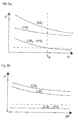
- FIG. 3a In the FIG. 3a are the voltage curves u ⁇ f 1 and u ⁇ f 2 , which are proportional to the resonance frequency change .DELTA.f 1 , .DELTA.f 2 of the two oscillating circuits 6, 11 are plotted over the distance .DELTA.s of the object 2.
- the curves show that the resonant frequency f 1 , f 2 of the two oscillating circuits 6, 11 and the resonance frequency change ⁇ f 1 , ⁇ f 2 and their proportional voltage u ⁇ f 1 , uAf 2 increase as the metallic object approaches. Due to the shielding layer 12 between the first oscillation circuit 6 and the second oscillation circuit 11, the resonance frequency change ⁇ f 2 is less inflexible than the resonance frequency change ⁇ f 1 .
- the comparator 14 compares the voltages of the resonant frequency changes u ⁇ f1 and u ⁇ f 2 , and if the two differentially evaluated voltages u ⁇ f 1 and u ⁇ f 2 exceed a predetermined value, the inductive proximity switch 1 switches on.
- the distance ⁇ s of the metallic object corresponds to the switching distance s r .
- a reference voltage may be applied, through which the user can set the switching distance s r .
- FIG. 3b are the waveforms of the resonant frequency changes .DELTA.f 1 and 2 or the .DELTA.f voltages proportional thereto u ⁇ f 1 and 2 UAF the two resonant circuits 6, can be seen.
- the voltages u ⁇ f 1 and uAf 2 are plotted as a function of the distance ⁇ R or the magnetic properties of the support frame 21.
- the support frame 21 may be made of any material, so that the resonance frequency f 1 , f 2 of the resonant circuits 6, 11 are influenced by the support frame 21.
- u ⁇ f 1 and uAf 2 increase slightly as the metallic support frame 21 approaches. Due to the differential evaluation in the comparator 14, however, the voltage difference u ⁇ f 1 -uAf 2 remains constant. The preset switching threshold or switching voltage u r is not exceeded, so that the inductive proximity switch 1 does not switch and the set switching distance s r remains constant.
- the sensor coil 6, the first shielding layer 12, the second sensor coil 7 and the second shielding layer 12 are preferably used as a printed circuit board coil or Planar coil formed in parallel and spaced in an axis.
- the evaluation unit 26 can be arranged with on the circuit board between the second shielding layer 12 and the frame 21 facing side of the housing 3.
- the second shielding layer 12 can also function as a ground plane for the electronic circuit.
- the shape of the coils is arbitrary. It can be selected square, rectangular, annular or polygonal shapes that are adapted to the outer geometry of the housing 3.
- the shielding layer 12 may be adapted to the geometry of the sensor coil 7 and surround the sensor coil 7 partially or completely.
Abstract
Bei einem induktiver Näherungsschalter (1) zur Erfassung eines Gegenstandes (2) in einem Überwachungsbereich (20), der aus mindestens einem elektrischen Schaltkreis (5) aufweist, der in einem Gehäuse (3) an einem Traggestell (21) befestigbar angeordnet ist, bestehend aus - einem Schwingkreis (6, 11) mit einer Parallelschaltung aus einer Sensorspule (7) und einem Kondensator (8), - aus einer Oszillatorschaltung (9), durch den der Schwingkreis (6, 11) in seiner Resonanzfrequenz (f 1 ) betrieben ist und - aus einer nachgeschalteten Auswerteeinheit (26), durch die ein Schaltsignal bei der Annäherung des Gegenstandes (2) generiert ist, soll der Schaltabstand (s r ) unabhängig von der Einbausituation und den magnetischen Eigenschaften des Traggestells (21) einstellbar seien. Diese Aufgabe ist dadurch gelöst, dass beabstandet zu dem ersten Schwingkreis (6) ein zweiter Schwingkreis (11) vorgesehen ist, dass der zweite Schwingkreis (11) durch eine zweite Oszillatorschaltung (9) in seiner Resonanzfrequenz (f 2 ) betrieben ist, dass zwischen dem ersten und dem zweiten Schwingkreis (6, 11) eine Abschirmschicht (12) angeordnet ist.In an inductive proximity switch (1) for detecting an object (2) in a monitoring area (20), which comprises at least one electrical circuit (5) which is arranged in a housing (3) fastened to a support frame (21) out a resonant circuit (6, 11) with a parallel circuit comprising a sensor coil (7) and a capacitor (8), - From an oscillator circuit (9) through which the resonant circuit (6, 11) in its resonant frequency (f 1) is operated and from a downstream evaluation unit (26), by which a switching signal is generated when the object (2) approaches, should the switching distance (s r) regardless of the installation situation and the magnetic properties of the support frame (21) are adjustable. This object is achieved in that at a distance from the first oscillating circuit (6) a second oscillating circuit (11) is provided, that the second resonant circuit (11) is operated by a second oscillator circuit (9) at its resonant frequency (f 2) the first and the second oscillating circuit (6, 11) a shielding layer (12) is arranged.
Description
Die Erfindung bezieht sich auf einen induktiver Näherungsschalter zur Erfassung eines Gegenstandes in einem Überwachungsbereich, nach dem Oberbegriff des Patentanspruches 1 sowie auf ein Verfahren für den Betrieb des induktiven Näherungsschalters nach dem Oberbegriff des Patentanspruches 10.The invention relates to an inductive proximity switch for detecting an object in a surveillance area, according to the preamble of
Derartige induktive Näherungsschalter sind im industriellen Einsatz vielseitig bewährt und dienen zur Erfassung des Abstandes von metallischen Gegenständen. Der induktive Näherungsschalter ist hierzu zur Befestigung an einem Traggestell befestigt und in einen Überwachungsbereich gerichtet. In der Literatur werden diese induktiven Näherungsschalter auch schweißfeste induktive Allmetallsensoren oder Allmetallschalter genannt.Such inductive proximity switches are versatilely proven in industrial applications and serve to detect the distance of metallic objects. The inductive proximity switch is attached for attachment to a support frame and directed into a surveillance area. In the literature, these inductive proximity switches are also called sweat-proof inductive all-metal sensors or all-metal switches.
Ein derartiger Sensor ist beispielsweise aus der
Nachteiliger Weise sind derartige Sensoren anfällig auf Temperaturschwankungen und zeigen ein instabiles Langzeitschaltverhalten. Temperaturänderungen und Materialalterung beispielsweise der Vergussmasse, verändern nämlich lokal die magnetischen Feldlinien und führen somit zu einem veränderten Schaltabstand oder sogar zum ungewollten Schaltverhalten.Disadvantageously, such sensors are susceptible to temperature fluctuations and show an unstable long-term switching behavior. Temperature changes and material aging, for example, the potting compound, namely locally change the magnetic field lines and thus lead to a changed operating distance or even unwanted switching behavior.
Eine weitere Ausführungsvariante des induktiven Näherungsschalters bzw. dessen elektrischen Schaltkreises ist mit einem LC-Schwingkreis ausgeführt, der mit einer vorgegebenen Frequenz betrieben ist. Ein derartig ausgeführter induktiver Näherungsschalter ist aus der
Technisch bedingt üben die sich nähernden Objekte oder Gegenstände aus andersartigen metallischen Werkstoffen auf den Schwingkreis unterschiedliche Einflüsse aus, und zwar in Abhängigkeit von den magnetischen Eigenschaften des Werkstoffes. Nachteiliger Weise ist folglich der Schaltabstand für unterschiedliche Werkstoffe in Abhängigkeit von den magnetischen oder nichtmagnetischen Eigenschaften einzustellen. Somit ist für jede Einbausituation des induktiven Näherungsschalters eine Voreinstellung zu treffen, um die Werkstoffeigenschaften des Traggestelles zu berücksichtigen. Solche Voreinstellungen sind technisch kompliziert und zeitintensiv.Technically, the approaching objects or objects made of different types of metallic materials exert different influences on the oscillatory circuit, depending on the magnetic properties of the material. Disadvantageously, therefore, the switching distance for different materials as a function of the magnetic or non-magnetic properties is set. Thus, for each installation situation of the inductive proximity switch to make a pre-setting to take into account the material properties of the support frame. Such presets are technically complicated and time consuming.
Aus der
Nachteilig bei diesem Stand der Technik ist die zwingende Vorkenntnis der Einbausituation und der magnetischen Eigenschaften des Traggestells. Dies führt nämlich dazu, dass der Schaltabstand nicht unabhängig von der Einbausituation einstellbar ist, bzw. dass der Schaltabstand in unterschiedlichen Einbausituationen variiert.A disadvantage of this prior art is the mandatory prior knowledge of the installation situation and the magnetic properties of the support frame. That is because this leads In addition, the switching distance can not be set independently of the installation situation, or the switching distance varies in different installation situations.
Ferner sind derartige Sensoren auf äußere magnetische Wechselfelder störanfällig. Ein äußeres magnetisches Wechselfeld induziert Wechselspannungen in die Sensorspule. Dies führt zu einem ungewünschten Schaltverhalten, so dass das Einsatzspektrum eines derart störanfälligen Sensors begrenzt ist. Auch statische magnetische Felder beeinflussen das Schaltverhalten derartiger induktiver Näherungsschalter, so dass abhängig von der Einbausituation des induktiven Näherungsschalters der Schaltabstand variiert.Furthermore, such sensors are susceptible to external magnetic alternating fields. An external alternating magnetic field induces AC voltages in the sensor coil. This leads to an undesired switching behavior, so that the range of use of such a fault-prone sensor is limited. Static magnetic fields also influence the switching behavior of such inductive proximity switches, so that the switching distance varies depending on the installation situation of the inductive proximity switch.
Es ist daher Aufgabe der Erfindung, einen induktiven Näherungsschalter und ein Verfahren zum Betrieb dessen der eingangs genannten Gattung zur Verfügung zu stellen, bei dem unabhängig von der Einbausituation und den magnetischen Eigenschaften des Traggestells ein konstanter Schaltabstand einstellbar ist.It is therefore an object of the invention to provide an inductive proximity switch and a method for operating the aforementioned type available, in which, regardless of the installation situation and the magnetic properties of the support frame, a constant switching distance is adjustable.
Diese Aufgabe ist erfindungsgemäß durch die Merkmale der kennzeichnenden Teile der Patentansprüche 1 und 10 gelöst.This object is achieved by the features of the characterizing parts of
Weitere vorteilhafte Weiterbildungen der Erfindung ergeben sich aus den Unteransprüchen.Further advantageous developments of the invention will become apparent from the dependent claims.
Dadurch, dass beabstandet zu dem ersten Schwingkreis ein zweiter Schwingkreis vorgesehen ist, dass der zweite Schwingkreis durch eine zweite Oszillatorschaltung in einer Resonanzfrequenz betrieben ist und dass zwischen dem ersten und dem zweiten Schwingkreis eine Abschirmschicht angeordnet ist, kann ein Schaltsignal bei der Annäherung eines magnetischen oder nichtmagnetischen metallischen Gegenstandes völlig unabhängig von der Einbausituation und den magnetischen Werkstoffeigenschaften des Traggestells bei konstantem Schaltabstand generiert sein, da durch die zwei Schwingkreise eine Kompensation der Einflüsse des Traggestelles ermöglicht ist.Characterized in that a second resonant circuit is provided spaced from the first resonant circuit, that the second resonant circuit is operated by a second oscillator circuit in a resonant frequency, and that a shielding layer is arranged between the first and the second oscillatory circuit, a switching signal can occur when approaching a magnetic or Non-magnetic metallic object to be generated completely independent of the installation situation and the magnetic material properties of the support frame at a constant switching distance, since a compensation of the influences of the support frame is made possible by the two resonant circuits.
Die beiden Schwingkreise, die durch ihre jeweilige Oszillatorschaltung in der Resonanzfrequenz zum Schwingen angeregt sind, werden durch die Annäherung eines metallischen Objektes und des Traggestells unterschiedlich beeinflusst. Bei der Annäherung eines metallischen Gegenstandes ist die Resonanzfrequenzänderung des ersten Schwingkreises höher als die Resonanzfrequenzänderung des zweiten Schwingkreises aufgrund der zwischen der ersten und dem zweiten Schwingkreis angeordneten Abschirmschicht. Der erste Schwingkreis ist dabei an der dem Überwachungsbereich zugewandten Seite des Gehäuses angeordnet und der zweite Schwingkreis parallel und beabstandet in einer Ebene zu dem ersten Schwingkreis in dem Gehäuse auf der dem Überwachungsbereich abgewandten Seite. Zwischen dem zweiten Schwingkreis und der dem Traggestell zugewandten Seite des Gehäuses kann eine zweite Abschirmschicht vorgesehen sein, so dass der Schaltabstand unabhängig von den Umgebungsbedingungen des induktiven Näherungsschalters eingestellt sein kann. Demnach kann der induktive Näherungsschalter auf metallischen, magnetischen bzw. metallisch nichtmagnetischen Traggestellen angeordnet bzw. befestigt sein, ohne dass der Schaltabstand verändert ist.The two resonant circuits, which are excited by their respective oscillator circuit in the resonant frequency to vibrate, are determined by the approximation of a metallic object and the support frame influenced differently. When approaching a metallic object, the resonance frequency change of the first resonant circuit is higher than the resonant frequency change of the second resonant circuit due to the arranged between the first and the second resonant circuit shielding layer. The first resonant circuit is arranged on the monitoring area facing the side of the housing and the second resonant circuit parallel and spaced in a plane to the first resonant circuit in the housing on the side remote from the monitoring area. A second shielding layer may be provided between the second resonant circuit and the side of the housing facing the support frame, so that the switching distance can be set independently of the ambient conditions of the inductive proximity switch. Accordingly, the inductive proximity switch can be arranged or fixed on metallic, magnetic or metallic non-magnetic support frames without the switching distance being changed.
Darüber hinaus ist es besonders vorteilhaft, dass den beiden Schwingkreisen ein Referenzoszillator zugeordnet ist und dass eine Frequenzänderung des jeweiligen Schaltkreises durch einen nachgeschalteten Mischer ermittelbar ist.Moreover, it is particularly advantageous that the two oscillating circuits is assigned a reference oscillator and that a change in frequency of the respective circuit can be determined by a downstream mixer.
Ein Komparator kann den Mischern nachgeschaltet sein, so dass der Komparator in Abhängigkeit von der Frequenzänderungen der beiden Schwingkreise ein Schaltsignal generiert. Durch den erfindungsgemäßen induktiven Näherungsschalter kann vorteilhafterweise der Schaltabstand unabhängig von den magnetischen Eigenschaften des metallischen Gegenstandes eingestellt werden. Durch das Auswerten der Resonanzfrequenzänderungen mittels der jeweiligen Referenzoszillatoren ist auch die Erfassung großer Schaltabstände möglich, da auch kleine Resonanzfrequenzänderungen erfassbar sind. Dies kann weiterhin vorteilhaft begünstigt sein, wenn die Frequenz des Referenzoszillators bis zu 10 Prozent niedriger ist als die Resonanzfrequenz des Schwingkreises.A comparator may be connected downstream of the mixers, so that the comparator generates a switching signal as a function of the frequency changes of the two oscillating circuits. By means of the inductive proximity switch according to the invention, the switching distance can advantageously be set independently of the magnetic properties of the metallic object. By evaluating the resonance frequency changes by means of the respective reference oscillators, the detection of large switching distances is also possible, since even small resonance frequency changes can be detected. This can also favorably favored, if the frequency of the reference oscillator is up to 10 percent lower than the resonant frequency of the resonant circuit.
In der Zeichnung ist ein erfindungsgemäßes Ausführungsbeispiel eines induktiven Näherungsschalters dargestellt, das nachfolgend näher erläutert ist. Im Einzelnen zeigt
Figur 1- einen induktiven Näherungsschalter, dessen Gehäuse eine flache rechteckige Bauform aufweist,
Figur 2- ein schematisches Schaltbild eines elektrischen Schaltkreises, durch den der induktiver Näherungsschalter gemäß
Figur 1 - Figur 3a
- ein Signalverlaufsdiagramm der beiden Schwingkreise gemäß
Figur 2 - Figur 3b
- ein Signalverlaufsdiagramm der Schwingkreise gemäß
Figur 2
- FIG. 1
- an inductive proximity switch whose housing has a flat rectangular shape,
- FIG. 2
- a schematic diagram of an electrical circuit through which the inductive proximity switch according to
FIG. 1 is formed, with a first and a second resonant circuit, which are each operated by an oscillator circuit in the resonant frequency, - FIG. 3a
- a signal waveform diagram of the two oscillatory circuits according to
FIG. 2 when approaching a magnetic object and - FIG. 3b
- a waveform diagram of the resonant circuits according to
FIG. 2 in a different installation situation on a metallic underground.
Der
Die Sensorabdeckungskappe 4 besteht aus einem nicht leitenden, nicht magnetischen Material, so dass in dem groß bemessenen Überwachungsbereich 20 der Gegenstand 2 erfassbar ist. Der induktive Näherungsschalter 1 ist mittels elektrischer Leitungen 25 mit einer geeigneten Auswerte- oder Schaltelektronik verbunden, durch die der induktive Näherungsschalter 1 gleichzeitig mit einer benötigten elektrischen Spannung versorgt wird.The
Der
Der elektrische Schaltkreis 5 des induktiven Näherungsschalters 1, besteht aus einem ersten Schwingkreis 6 und einem zweiten Schwingkreis 11. Die Schwingkreise 6, 11 sind durch eine Parallelschaltung einer Sensorspule 7 mit einem Kondensator 8 gebildet und werden durch eine Oszillatorschaltung 9 in Schwingung versetzt. Der jeweilige elektrische Schwingkreis 6, 11 schwingt demnach in seiner Resonanzfrequenz f1, f2. Die Frequenzen f1, f2 in den die Schwingkreise 6, 11 durch die jeweilige Oszillatorschaltung 9 betrieben sind können unterschiedlich hoch bemessen sein.The
Der erste und der zweite Schwingkreis 6, 11 sind jeweils in einer Ebene parallel und beabstandet zueinander angeordnet. Der erste Schwingkreis 6 ist dabei auf der dem Überwachungsbereich 20 zugewandten Seite des Gehäuse 3 parallel und beabstandet unterhalb der Sensorabdeckungskappe 4 angeordnet.The first and second
Zwischen dem ersten Schwingkreis 6 und dem zweiten Schwingkreis 11 ist eine erste Abschirmschicht 12 angeordnet. Eine zweite Abschirmschicht 12 ist darüber hinaus zwischen dem zweiten Schwingkreis 11 und der dem Traggestell 21 zugewandten Seite des Gehäuses 3 vorgesehen. Die Abschirmschichten 12 sind vorzugsweise aus einem metallischen und nicht magnetischen Werkstoff gebildet, vorzugsweise Kupfer.Between the first resonant circuit 6 and the second
Dem jeweiligen Schwingkreis 6, 11 ist ein Mischer 13 nachgeschaltet, der mit einem Referenzoszillator 10 verbunden ist. Der Referenzoszillator 10 ist als quarzstabiler Oszillator ausgebildet. Der Mischer 13 bildet aus den Frequenzen f1, f2 der Schwingkreise 6, 11 jeweils eine Mischfrequenz, die der Frequenzänderung des jeweiligen Schwingkreises 6, 11 entspricht. Die Mischfrequenzen Δf1, Δf2 sind in eine proportionale Spannung uΔf1, uAf2 gewandelt.The respective
Ein Komparator 14 wertet differenziell die beiden Spannungen uΔf1 und uΔf2 der beiden Mischer 13 aus und gibt bei der Annäherung eines metallischen Gegenstandes 2 ein Schaltsignal aus.A
In der
An dem Komparator 14 kann eine Referenzspannung angelegt sein, durch die der Anwender den Schaltabstand sr einstellen kann.At the
In
Die Sensorspule 6, die erste Abschirmschicht 12, die zweite Sensorspule 7 und die zweite Abschirmschicht 12 werden vorzugsweise als Leiterplattenspule bzw. Planarspule parallel und beabstandet in einer Achse ausgebildet. Die Auswerteeinheit 26 kann dabei mit auf der Leiterplatte zwischen der zweiten Abschirmschicht 12 und der dem Gestell 21 zugewandten Seite des Gehäuses 3 angeordnet sein. Die zweite Abschirmschicht 12 kann gleichzeitig auch als Massefläche für die elektronische Schaltung fungieren. Somit ist es möglich, die Sendespulen 7 größtmöglich auszugestalten, um eine größtmögliche Reichweite des Überwachungsbereiches 20 zu erzielen und gleichzeitig eine kleine Bauform des Gehäuses 3 zu gewährleisten.The sensor coil 6, the
Die Form der Spulen ist beliebig wählbar. Es können quadratische, rechteckige, ringförmige oder vieleckige Formen gewählt werden, die an die Außengeometrie des Gehäuses 3 angepasst sind. Darüber hinaus kann die Abschirmschicht 12 an die Geometrie der Sensorspule 7 angepasst sein und die Sensorspule 7 teilweise oder ganz umgreifen.The shape of the coils is arbitrary. It can be selected square, rectangular, annular or polygonal shapes that are adapted to the outer geometry of the
Claims (12)
dass beabstandet zu dem ersten Schwingkreis (6) ein zweiter Schwingkreis (11) vorgesehen ist, dass der zweite Schwingkreis (11) durch eine zweite Oszillatorschaltung (9) in seiner Resonanzfrequenz (f2) betrieben ist, dass zwischen dem ersten und dem zweiten Schwingkreis (6, 11) eine Abschirmschicht (12) angeordnet istInductive proximity switch (1) for detecting an object (2) in a surveillance area (20) comprising at least one electrical circuit (5) which is fastened in a housing (3) to a support frame (21), consisting of
in that a second oscillating circuit (11) is provided spaced from the first oscillating circuit (6), that the second oscillating circuit (11) is operated by a second oscillator circuit (9) at its resonant frequency (f 2 ) between the first and the second oscillating circuit (6, 11) a shielding layer (12) is arranged
dadurch gekennzeichnet,
dass der erste Schwingkreis (6) in dem Gehäuse (3) an der dem Überwachungsbereich (20) zugewandten Seite angeordnet ist, dass der zweite Schwingkreis (11) in einer Ebene parallel und beabstandet zu der Ebene des ersten Schwingkreis (6) im Gehäuse (3) an der dem Überwachungsbereich (20) abgewandten Seite angeordnet ist.Inductive proximity switch (1) according to claim 1,
characterized,
that the first oscillation circuit (6) in the housing (3) is arranged on the the monitoring area (20) facing side, that the second resonant circuit (11) in a plane parallel to and spaced from the plane of the first resonant circuit (6) in the housing ( 3) is arranged on the side facing away from the monitoring area (20).
dadurch gekennzeichn
dass zwischen dem zweiten Schwingkreis (11) und der dem Traggestell (21) zugewandten Seite des Gehäuses (3) eine zweite Abschirmschicht (12) vorgesehen ist.Inductive proximity switch (1) according to claim 1 or 2,
characterized
a second shielding layer (12) is provided between the second oscillating circuit (11) and the side of the housing (3) facing the support frame (21).
dadurch gekennzeichn
dass jedem Schwingkreis (6, 11) ein Referenzoszillator (10) zugeordnet ist und dass eine Frequenz-Änderung (Δf) des jeweiligen Schwingkreises (6, 11) durch jeweils einen nachgeordneten Mischer (13) ermittelbar ist.Inductive proximity switch (1) according to one of the preceding claims,
characterized
a reference oscillator (10) is associated with each resonant circuit (6, 11) and that a frequency change (Δ f ) of the respective resonant circuit (6, 11) can be determined by a respective downstream mixer (13).
dadurch gekennzeichnet,
dass ein Komparator (14) den Mischern (13) nachgeschaltet ist, und dass der Komparator (14) in Abhängigkeit von den Frequenz-Änderungen (Δf1, Δf2) der Schwingkreise (6, 11) ein Schaltsignal auswertbares generiert.Inductive proximity switch (1) according to claim 4,
characterized,
in that a comparator (14) is connected downstream of the mixers (13), and in that the comparator (14) generates a switchable signal as a function of the frequency changes (Δf 1 , Δf 2 ) of the oscillating circuits (6, 11).
dadurch gekennzeichnet,
dass der Referenzoszillator (10) als quarzstabiler Oszillator ausgestaltet ist und dass der Referenzoszillator (10) mit einer geringfügig höheren Frequenz (f3) angeregt ist als die der Oszillatorschaltungen (9).Inductive proximity switch (1) according to claim 4,
characterized,
that the reference oscillator (10) is designed as a quartz-stable oscillator and that the reference oscillator (10) is excited at a slightly higher frequency (f 3 ) than that of the oscillator circuits (9).
dadurch gekennzeichnet,
dass der Mischer (11), der Referenzoszillator (10) und der Komparator (14) in einem programmierbaren Logikbaustein eingebaut sind und dass die Sendespulen (7) als Planarspulen ohne Ferritkern ausgebildet sind.Inductive proximity switch (1) according to claim 4,
characterized,
in that the mixer (11), the reference oscillator (10) and the comparator (14) are installed in a programmable logic module and that the transmitting coils (7) are designed as planar coils without a ferrite core.
dadurch gekennzeichnet,
dass der Referenzoszillator (10) in einer höheren/oder niedrigeren Frequenz (f3) als die Oszillatorschaltungen (9) betrieben ist.Inductive proximity switch (1) according to claim 4,
characterized,
that the reference oscillator (10) in a higher / or lower frequency (f 3) is operated as the oscillator circuits (9).
dadurch gekennzeichnet,
dass die Abschirmschicht (12) aus einem gut leitfähigen Werkstoff, vorzugsweise ein metallischer Werkstoff, gebildet ist und dass der Abschirmschicht (12) die Sensorspule (7) teileweise oder ganz umgibt.Inductive proximity switch (1) according to one of the preceding claims
characterized,
in that the shielding layer (12) is formed from a highly conductive material, preferably a metallic material, and that the shielding layer (12) partially or completely surrounds the sensor coil (7).
gekennzeichnet durch die nachfolgenden Verfahrensschritte:
characterized by the following method steps:
gekennzeichnet durch
Bilden der Frequenz-Änderungen (Δf1, Δf2) aus den Resonanzfrequenzen (f1, f2) der Schwingkreise (4,) und der Referenzfrequenz (f3) des Referenzoszillators (10).Method according to claim 8,
marked by
Forming the frequency changes (Δ f1 , Δ f2 ) from the resonance frequencies (f 1 , f 2 ) of the oscillating circuits (4,) and the reference frequency (f 3 ) of the reference oscillator (10).
gekennzeichnet durch
Erzeugen des Schaltsignals (24) durch ein Komparator (14) in Abhängigkeit von den Resonanzfrequenzänderungen (Δf1, Δf2).Method according to claim 8 or 9,
marked by
Generating the switching signal (24) by a comparator (14) as a function of the resonance frequency changes (Δ f1 , Δ f2 ).
Applications Claiming Priority (1)
| Application Number | Priority Date | Filing Date | Title |
|---|---|---|---|
| DE102014016217.6A DE102014016217A1 (en) | 2014-10-31 | 2014-10-31 | Inductive proximity switch and control method for its operation |
Publications (1)
| Publication Number | Publication Date |
|---|---|
| EP3016284A1 true EP3016284A1 (en) | 2016-05-04 |
Family
ID=53938209
Family Applications (1)
| Application Number | Title | Priority Date | Filing Date |
|---|---|---|---|
| EP15181812.7A Withdrawn EP3016284A1 (en) | 2014-10-31 | 2015-08-20 | Inductive proximity switch and method for operating the same |
Country Status (2)
| Country | Link |
|---|---|
| EP (1) | EP3016284A1 (en) |
| DE (1) | DE102014016217A1 (en) |
Cited By (1)
| Publication number | Priority date | Publication date | Assignee | Title |
|---|---|---|---|---|
| CN109000550A (en) * | 2018-08-25 | 2018-12-14 | 成都凯天电子股份有限公司 | Coil magnetic field protected type proximity sensor |
Families Citing this family (2)
| Publication number | Priority date | Publication date | Assignee | Title |
|---|---|---|---|---|
| DE102020107100A1 (en) | 2020-03-16 | 2021-09-16 | Wenglor sensoric elektronische Geräte GmbH | Electrically operated measuring device |
| EP4125215A1 (en) | 2021-07-27 | 2023-02-01 | wenglor sensoric elektronische Geräte GmbH | Electrical circuit, in particular for an inductively operated proximity switch |
Citations (6)
| Publication number | Priority date | Publication date | Assignee | Title |
|---|---|---|---|---|
| DE3244449A1 (en) * | 1981-12-03 | 1983-06-16 | Omron Tateisi Electronics Co., Kyoto | PROXIMITY SWITCH |
| DE3912946C3 (en) | 1989-04-20 | 1996-06-20 | Turck Werner Kg | Inductive proximity switch |
| DE10244104B4 (en) | 2002-09-23 | 2006-02-23 | Wenglor Sensoric Gmbh | Inductive proximity switch |
| DE102005045711B4 (en) | 2005-09-24 | 2007-08-23 | Werner Turck Gmbh & Co. Kg | Inductive sensor |
| US20090243601A1 (en) * | 2008-03-28 | 2009-10-01 | Martin Feldtkeller | Inductive Proximity Switch |
| DE102010043506B3 (en) * | 2010-11-05 | 2012-04-26 | Ifm Electronic Gmbh | Inductive proximity switch for use as contactlessly working electronic switching device in automation technology, has evaluation circuit including synchronous rectifier for phase-sensitive rectification of oscillating circuit output signal |
-
2014
- 2014-10-31 DE DE102014016217.6A patent/DE102014016217A1/en active Granted
-
2015
- 2015-08-20 EP EP15181812.7A patent/EP3016284A1/en not_active Withdrawn
Patent Citations (6)
| Publication number | Priority date | Publication date | Assignee | Title |
|---|---|---|---|---|
| DE3244449A1 (en) * | 1981-12-03 | 1983-06-16 | Omron Tateisi Electronics Co., Kyoto | PROXIMITY SWITCH |
| DE3912946C3 (en) | 1989-04-20 | 1996-06-20 | Turck Werner Kg | Inductive proximity switch |
| DE10244104B4 (en) | 2002-09-23 | 2006-02-23 | Wenglor Sensoric Gmbh | Inductive proximity switch |
| DE102005045711B4 (en) | 2005-09-24 | 2007-08-23 | Werner Turck Gmbh & Co. Kg | Inductive sensor |
| US20090243601A1 (en) * | 2008-03-28 | 2009-10-01 | Martin Feldtkeller | Inductive Proximity Switch |
| DE102010043506B3 (en) * | 2010-11-05 | 2012-04-26 | Ifm Electronic Gmbh | Inductive proximity switch for use as contactlessly working electronic switching device in automation technology, has evaluation circuit including synchronous rectifier for phase-sensitive rectification of oscillating circuit output signal |
Cited By (2)
| Publication number | Priority date | Publication date | Assignee | Title |
|---|---|---|---|---|
| CN109000550A (en) * | 2018-08-25 | 2018-12-14 | 成都凯天电子股份有限公司 | Coil magnetic field protected type proximity sensor |
| CN109000550B (en) * | 2018-08-25 | 2019-12-27 | 成都凯天电子股份有限公司 | Coil magnetic field shielding type proximity sensor |
Also Published As
| Publication number | Publication date |
|---|---|
| DE102014016217A1 (en) | 2016-05-04 |
Similar Documents
| Publication | Publication Date | Title |
|---|---|---|
| EP1797464B1 (en) | Detector for locating metallic objects | |
| DE102004047188B4 (en) | Device for locating metallic objects | |
| DE102010007620B9 (en) | Proximity sensor | |
| EP2567262B1 (en) | Detection of a metal or magnetic object | |
| EP3510361B1 (en) | Rotary sensor and stator element for same | |
| EP3016284A1 (en) | Inductive proximity switch and method for operating the same | |
| DE102008063527A1 (en) | Circuit arrangement and method for evaluating a sensor | |
| WO2003046612A1 (en) | Metal detector | |
| DE102012214330B3 (en) | Inductive proximity switch for use as contactless working electronic switching device in automatic control engineering field, has receiving coils that are arranged in outer region of winding body | |
| DE10222186C1 (en) | Safety switch has comparator providing switch signal if energy induced in receiver element during period following electromagnetic signal emission exceeds/falls below predefined threshold | |
| EP2936212B1 (en) | Sensor for locating metal or magnetic objects | |
| EP3824323B1 (en) | Detector for detecting electrically conductive material | |
| DE10032864A1 (en) | Proximity sensor, has attachment section containing sensor head and connected electronic section with at least one sensor signal evaluation unit and power supply | |
| DE102020100939A1 (en) | Proximity switch and method for detecting an object to be detected | |
| EP3146591A1 (en) | Distance measuring device, in particular for dielectric and metallic target objects | |
| EP3640896B1 (en) | Vehicle door handle with near field communication electronics | |
| EP3015826B1 (en) | Sensor device, operating tool and method for operating the same | |
| DE4210018C2 (en) | Weldable inductive proximity switch | |
| DE102013100841B4 (en) | Position transducer with a sensor element and a plunger coil | |
| DE102022208616A1 (en) | Inductive sensor arrangement for determining a rotation angle or a difference angle | |
| EP3569466A1 (en) | Sensor for detecting metal parts and method for reducing a magnetic field | |
| DE102011100440A1 (en) | position sensor | |
| DE102019103670A1 (en) | Inductive sensor and method of its operation | |
| DE202014103313U1 (en) | Inductive proximity sensor | |
| EP2184623A2 (en) | Sensor device for detecting an object and its movement in a measurement area of the sensor device |
Legal Events
| Date | Code | Title | Description |
|---|---|---|---|
| PUAI | Public reference made under article 153(3) epc to a published international application that has entered the european phase |
Free format text: ORIGINAL CODE: 0009012 |
|
| AK | Designated contracting states |
Kind code of ref document: A1 Designated state(s): AL AT BE BG CH CY CZ DE DK EE ES FI FR GB GR HR HU IE IS IT LI LT LU LV MC MK MT NL NO PL PT RO RS SE SI SK SM TR |
|
| AX | Request for extension of the european patent |
Extension state: BA ME |
|
| STAA | Information on the status of an ep patent application or granted ep patent |
Free format text: STATUS: THE APPLICATION HAS BEEN PUBLISHED |
|
| STAA | Information on the status of an ep patent application or granted ep patent |
Free format text: STATUS: THE APPLICATION IS DEEMED TO BE WITHDRAWN |
|
| 18D | Application deemed to be withdrawn |
Effective date: 20161105 |