EP3016280A1 - Frequency tripler and local oscillator signal generator - Google Patents
Frequency tripler and local oscillator signal generator Download PDFInfo
- Publication number
- EP3016280A1 EP3016280A1 EP15178854.4A EP15178854A EP3016280A1 EP 3016280 A1 EP3016280 A1 EP 3016280A1 EP 15178854 A EP15178854 A EP 15178854A EP 3016280 A1 EP3016280 A1 EP 3016280A1
- Authority
- EP
- European Patent Office
- Prior art keywords
- frequency
- signal
- double
- phase
- quadrature
- Prior art date
- Legal status (The legal status is an assumption and is not a legal conclusion. Google has not performed a legal analysis and makes no representation as to the accuracy of the status listed.)
- Ceased
Links
- 238000010586 diagram Methods 0.000 description 4
- 230000004075 alteration Effects 0.000 description 1
- 230000001419 dependent effect Effects 0.000 description 1
- 238000011161 development Methods 0.000 description 1
- 230000018109 developmental process Effects 0.000 description 1
- 238000000034 method Methods 0.000 description 1
- 238000012986 modification Methods 0.000 description 1
- 230000004048 modification Effects 0.000 description 1
Images


Classifications
-
- H—ELECTRICITY
- H03—ELECTRONIC CIRCUITRY
- H03K—PULSE TECHNIQUE
- H03K5/00—Manipulating of pulses not covered by one of the other main groups of this subclass
- H03K5/00006—Changing the frequency
-
- H—ELECTRICITY
- H03—ELECTRONIC CIRCUITRY
- H03B—GENERATION OF OSCILLATIONS, DIRECTLY OR BY FREQUENCY-CHANGING, BY CIRCUITS EMPLOYING ACTIVE ELEMENTS WHICH OPERATE IN A NON-SWITCHING MANNER; GENERATION OF NOISE BY SUCH CIRCUITS
- H03B19/00—Generation of oscillations by non-regenerative frequency multiplication or division of a signal from a separate source
- H03B19/06—Generation of oscillations by non-regenerative frequency multiplication or division of a signal from a separate source by means of discharge device or semiconductor device with more than two electrodes
- H03B19/14—Generation of oscillations by non-regenerative frequency multiplication or division of a signal from a separate source by means of discharge device or semiconductor device with more than two electrodes by means of a semiconductor device
Definitions
- a frequency tripler is built in a local oscillator (LO) generator to generate an output signal whose frequency is three times of an input frequency to prevent a power amplifier from pulling the oscillator.
- the output signal generated from the conventional frequency tripler includes a fundamental harmonic frequency or a second harmonic frequency, and these harmonic frequencies may influence operations of the following stages.
- a frequency tripler comprises a double-frequency in-phase signal generator, a double-frequency quadrature signal generator and a mixer.
- the double-frequency in-phase signal generator is arranged for receiving at least an in-phase signal and a quadrature signal to generate a double-frequency in-phase signal whose frequency is twice that of the in-phase signal or the quadrature signal;
- the double-frequency quadrature signal generator is arranged for receiving at least the in-phase signal and the quadrature signal to generate a double-frequency quadrature signal whose frequency is twice that of the in-phase signal or the quadrature signal;
- the mixer is arranged for receiving the in-phase signal, the quadrature signal, the double-frequency in-phase signal and the double-frequency quadrature signal to generate an output signal whose frequency is triple that of the in-phase signal or the quadrature signal.
- a local oscillator generator comprises a signal generator and a frequency tripler, where the frequency tripler comprises a double-frequency in-phase signal generator, a double-frequency quadrature signal generator and a mixer.
- the signal generator is arranged for generating at least an in-phase signal and a quadrature signal;
- the double-frequency in-phase signal generator is arranged for receiving at least the in-phase signal and the quadrature signal to generate a double-frequency in-phase signal whose frequency is twice that of the in-phase signal or the quadrature signal;
- the double-frequency quadrature signal generator is arranged for receiving at least the in-phase signal and the quadrature signal to generate a double-frequency quadrature signal whose frequency is twice that of the in-phase signal or the quadrature signal;
- the mixer is arranged for receiving the in-phase signal, the quadrature signal, the double-frequency in-phase signal and the double-frequency quadrature signal to generate an output signal whose frequency is triple that of the in-phase signal or the quadrature signal.
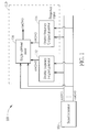
- FIG. 1 is a diagram illustrating a local oscillator (LO) generator 100 according to one embodiment of the present invention.
- the LO generator 100 comprises a signal generator 102 and a frequency tripler 110, where the frequency tripler 110 comprises a double-frequency in-phase signal generator 112, a double-frequency quadrature signal generator 114 and a mixer (in this embodiment, the mixer is implemented by a single sideband mixer 116).
- the signal generator 102 may be implemented by a voltage-controlled delay line (VCDL), a poly phase filter, a quadrature voltage-controlled oscillator, a phase shifter, or any other circuit capable of generating in-phase and quadrature signals.
- VCDL voltage-controlled delay line
- the signal generator 102 is arranged to generate at least an in-phase signal cos( ⁇ t) and a quadrature signal sin( ⁇ t).
- the signal generator 102 is arranged to generate four-phase IQ signals, that is four signals sin( ⁇ t), cos( ⁇ t), -sin( ⁇ t) and -cos( ⁇ t).
- the double-frequency in-phase signal generator 112 receives at least at least a portion of the IQ signals generated from the signal generator 102 to generate a double-frequency in-phase signal cos(2 ⁇ t) whose frequency is twice that of the in-phase signal cos( ⁇ t) and the quadrature signal sin( ⁇ t); and the double-frequency quadrature signal generator 114 receives at least at least a portion of the IQ signals to generate a double-frequency quadrature signal sin(2 ⁇ t) whose frequency is twice that of the in-phase signal cos( ⁇ t) and the quadrature signal sin( ⁇ t).
- the single sideband mixer 116 receives the in-phase signal cos( ⁇ t), the quadrature signal sin( ⁇ t), the double-frequency in-phase signal cos(2 ⁇ t) and the double-frequency quadrature signal sin(2 ⁇ t) to generate an output signal cos(3 ⁇ t) whose frequency is triple that of the in-phase signal cos( ⁇ t) and the quadrature signal sin( ⁇ t).
- the multiplier 222 multiplies sin( ⁇ t ) by sin( ⁇ t) to generate sin 2 ( ⁇ t)
- the multiplier 224 multiplies cos( ⁇ t) by cos( ⁇ t) to generate cos 2 ( ⁇ t )
- the combiner 226 subtracts sin 2 ( ⁇ t ) from cos 2 ( ⁇ t ) to obtain cos(2 ⁇ t).
- the multiplier 212 multiplies -cos( ⁇ t) by -sin( ⁇ t) to generate cos( ⁇ t )sin( ⁇ t )
- the multiplier 214 multiplies cos( ⁇ t) by sin( ⁇ t) to generate cos( ⁇ t )sin( ⁇ t )
- the combiner 216 combines outputs of the multipliers 212 and 214 to obtain sin(2 ⁇ t).
- the multiplier 232 multiplies sin(2 ⁇ t) by sin( ⁇ t)
- the multiplier 234 multiplies cos(2 ⁇ t) by cos ( ⁇ t)
- the combiner 216 subtracts sin(2 ⁇ t)sin( ⁇ t ) from cos(2 ⁇ t )cos( ⁇ t ) to obtain cos (3 ⁇ t).
- the output signal of the frequency tripler 110 does not have any fundamental harmonic frequency/spur or any second harmonic frequency/spur such as cos( ⁇ t), sin( ⁇ t), cos(2 ⁇ t) and/or sin(2 ⁇ t). Therefore, the frequency tripler 110 improves the situation of the output signal of the frequency tripler 110 and rejects fundamental/second harmonic spurs.
- FIG. 3 shows a circuit structure of the frequency tripler 110 according to one embodiment of the present invention.
- a plurality of transistors are arranged in cascoded structure to implement a double-frequency in-phase signal generator 312, a double-frequency quadrature signal generator 314 and a single sideband mixer 316 to generate the output signal cos(3 ⁇ t), where the symbols S, C, SB, CB correspond to sin( ⁇ t), cos( ⁇ t), -sin( ⁇ t) and -cos( ⁇ t) shown in FIG.
- the frequency tripler 110 can generate the output signal without any unwanted tone.
- an inductor L shown in FIG. 3 may be replaced by a resistor.
- the cascoded implementation shown in FIG. 3 is for illustrative purposes only, and is not a limitation of the present invention.
- the frequency tripler 110 can be implemented by folded cascoded or two stages circuit structure. Because a person skilled in the art should understand how to implement the frequency tripler 110 by using folded cascoded or two stages circuit structure with reference to the disclosure in FIG. 2 and FIG. 3 , further descriptions are omitted here.
- the output signal cos(3 ⁇ t) is generated in response to the double-frequency in-phase signal and the double-frequency quadrature signal.
- the double-frequency in-phase signal and the double-frequency quadrature signal are therefore obtained first, and then, the triple frequency can be obtained without any unwanted tone. The power efficiency is thus improved.
- the frequency tripler 110 is insensitive to input mismatch and has better performance in spur rejection.
- the frequency tripler in the frequency tripler of the present invention, can generate the output signal without any unwanted tone (i.e. without any fundamental harmonic frequency/spur or second harmonic frequency/spur) based on trigonometric formula. Therefore, the frequency tripler is good at fundamental/second harmonic spur rejection.
Landscapes
- Physics & Mathematics (AREA)
- Nonlinear Science (AREA)
- Superheterodyne Receivers (AREA)
- Amplitude Modulation (AREA)
- Transmitters (AREA)
Abstract
Description
- In a conventional radio frequency (RF) system, a frequency tripler is built in a local oscillator (LO) generator to generate an output signal whose frequency is three times of an input frequency to prevent a power amplifier from pulling the oscillator. However, the output signal generated from the conventional frequency tripler includes a fundamental harmonic frequency or a second harmonic frequency, and these harmonic frequencies may influence operations of the following stages.
- It is therefore an objective of the present invention to provide a frequency tripler and associated LO generator, whose output signal does not include any fundamental harmonic frequency and any second harmonic frequency, to solve the above-mentioned problems.
- This is achieved by a frequency tripler to claim 1 and an LO generator to claim 7. The dependent claims pertain to corresponding further developments and improvements.
- As will be seen more clearly from the detailed description following below, a frequency tripler comprises a double-frequency in-phase signal generator, a double-frequency quadrature signal generator and a mixer. The double-frequency in-phase signal generator is arranged for receiving at least an in-phase signal and a quadrature signal to generate a double-frequency in-phase signal whose frequency is twice that of the in-phase signal or the quadrature signal; the double-frequency quadrature signal generator is arranged for receiving at least the in-phase signal and the quadrature signal to generate a double-frequency quadrature signal whose frequency is twice that of the in-phase signal or the quadrature signal; and the mixer is arranged for receiving the in-phase signal, the quadrature signal, the double-frequency in-phase signal and the double-frequency quadrature signal to generate an output signal whose frequency is triple that of the in-phase signal or the quadrature signal.
- As will be seen more clearly from the detailed description following below, a local oscillator generator comprises a signal generator and a frequency tripler, where the frequency tripler comprises a double-frequency in-phase signal generator, a double-frequency quadrature signal generator and a mixer. The signal generator is arranged for generating at least an in-phase signal and a quadrature signal; the double-frequency in-phase signal generator is arranged for receiving at least the in-phase signal and the quadrature signal to generate a double-frequency in-phase signal whose frequency is twice that of the in-phase signal or the quadrature signal; the double-frequency quadrature signal generator is arranged for receiving at least the in-phase signal and the quadrature signal to generate a double-frequency quadrature signal whose frequency is twice that of the in-phase signal or the quadrature signal; and the mixer is arranged for receiving the in-phase signal, the quadrature signal, the double-frequency in-phase signal and the double-frequency quadrature signal to generate an output signal whose frequency is triple that of the in-phase signal or the quadrature signal.
- These and other objectives of the present invention will no doubt become obvious to those of ordinary skill in the art after reading the following detailed description of the preferred embodiment that is illustrated in the various figures and drawings.
-
-
FIG. 1 is a diagram illustrating a local oscillator generator according to one embodiment of the present invention. -
FIG. 2 , which is a diagram illustrating operations of the frequency tripler according to one embodiment of the present invention. -
FIG. 3 shows a circuit structure of the frequency tripler according to one embodiment of the present invention. - Certain terms are used throughout the following description and claims to refer to particular system components. As one skilled in the art will appreciate, manufacturers may refer to a component by different names. This document does not intend to distinguish between components that differ in name but not function. In the following discussion and in the claims, the terms "including" and "comprising" are used in an open-ended fashion, and thus should be interpreted to mean "including, but not limited to ..." The terms "couple" and "couples" are intended to mean either an indirect or a direct electrical connection. Thus, if a first device couples to a second device, that connection may be through a direct electrical connection, or through an indirect electrical connection via other devices and connections.
- Please refer to
FIG. 1 , which is a diagram illustrating a local oscillator (LO)generator 100 according to one embodiment of the present invention. As shown inFIG. 1 , theLO generator 100 comprises asignal generator 102 and afrequency tripler 110, where thefrequency tripler 110 comprises a double-frequency in-phase signal generator 112, a double-frequencyquadrature signal generator 114 and a mixer (in this embodiment, the mixer is implemented by a single sideband mixer 116). In this embodiment, thesignal generator 102 may be implemented by a voltage-controlled delay line (VCDL), a poly phase filter, a quadrature voltage-controlled oscillator, a phase shifter, or any other circuit capable of generating in-phase and quadrature signals. - In the operations of the
LO generator 100, thesignal generator 102 is arranged to generate at least an in-phase signal cos(ωt) and a quadrature signal sin(ωt). In this embodiment, thesignal generator 102 is arranged to generate four-phase IQ signals, that is four signals sin(ω t), cos(ωt), -sin(ωt) and -cos(ωt). Then, the double-frequency in-phase signal generator 112 receives at least at least a portion of the IQ signals generated from thesignal generator 102 to generate a double-frequency in-phase signal cos(2ωt) whose frequency is twice that of the in-phase signal cos(ωt) and the quadrature signal sin(ωt); and the double-frequencyquadrature signal generator 114 receives at least at least a portion of the IQ signals to generate a double-frequency quadrature signal sin(2 ωt) whose frequency is twice that of the in-phase signal cos(ωt) and the quadrature signal sin(ωt). Finally, thesingle sideband mixer 116 receives the in-phase signal cos(ωt), the quadrature signal sin(ωt), the double-frequency in-phase signal cos(2 ωt) and the double-frequency quadrature signal sin(2ωt) to generate an output signal cos(3 ωt) whose frequency is triple that of the in-phase signal cos(ωt) and the quadrature signal sin(ωt). - Please refer to
FIG. 2 , which is a diagram illustrating operations of thefrequency tripler 110 according to one embodiment of the present invention. As shown inFIG. 2 , the double-frequency in-phase signal generator 112 comprises twomultipliers combiner 226, where themultipliers combiner 226 are used to generate the double-frequency in-phase signal cos(2ωt) by using formula cos(2ωt)=cos2(ωt)-sin2(ωt). In detail, themultiplier 222 multiplies sin(ωt) by sin(ωt) to generate sin2(ωt), themultiplier 224 multiplies cos(ωt) by cos(ωt) to generate cos2(ωt), and the combiner 226 subtracts sin2(ωt) from cos2(ωt) to obtain cos(2 ωt). The double-frequencyquadrature signal generator 114 comprises twomultipliers combiner 216, where themultipliers combiner 216 are used to generate the double-frequency quadrature signal sin(2ωt) by using formula sm(2ωt)=2cos(ωt)sin(ωt). In detail, themultiplier 212 multiplies -cos(ωt) by -sin(ωt) to generate cos(ωt)sin(ωt), themultiplier 214 multiplies cos(ωt) by sin(ωt) to generate cos(ωt)sin(ωt), and thecombiner 216 combines outputs of themultipliers single sideband mixer 116 comprises twomultipliers combiner 236, where themultipliers combiner 236 are used to generate the output signal by using formula cos(3ωt)=cos(2ωt)cos(ωt)-sin(2ωt)sin(ωt). In detail, themultiplier 232 multiplies sin(2ωt) by sin(ωt), themultiplier 234 multiplies cos(2ωt) by cos (ωt), and the combiner 216 subtracts sin(2ωt)sin(ωt) from cos(2ωt)cos(ωt) to obtain cos (3 ωt). In the aforementioned operations of thefrequency tripler 110, the output signal of thefrequency tripler 110 does not have any fundamental harmonic frequency/spur or any second harmonic frequency/spur such as cos(ωt), sin(ωt), cos(2ωt) and/or sin(2ωt). Therefore, thefrequency tripler 110 improves the situation of the output signal of thefrequency tripler 110 and rejects fundamental/second harmonic spurs. -
FIG. 3 shows a circuit structure of thefrequency tripler 110 according to one embodiment of the present invention. InFIG. 3 , a plurality of transistors are arranged in cascoded structure to implement a double-frequency in-phase signal generator 312, a double-frequencyquadrature signal generator 314 and asingle sideband mixer 316 to generate the output signal cos(3ωt), where the symbols S, C, SB, CB correspond to sin(ωt), cos(ωt), -sin(ωt) and -cos(ωt) shown inFIG. 2 , respectively, and the operations of the double-frequency in-phase signal generator 312 and the double-frequencyquadrature signal generator 314 are similar to that of the double-frequency in-phase signal generator 112 and the double-frequencyquadrature signal generator 114, but the two-phases outputs are implemented. By using the cascoded implementation ofFIG. 3 , thefrequency tripler 110 can generate the output signal without any unwanted tone. - It is noted that an inductor L shown in
FIG. 3 may be replaced by a resistor. In addition, the cascoded implementation shown inFIG. 3 is for illustrative purposes only, and is not a limitation of the present invention. In other embodiments, thefrequency tripler 110 can be implemented by folded cascoded or two stages circuit structure. Because a person skilled in the art should understand how to implement thefrequency tripler 110 by using folded cascoded or two stages circuit structure with reference to the disclosure inFIG. 2 andFIG. 3 , further descriptions are omitted here. - In the
frequency tripler 100 shown inFIG. 1 - FIG. 3 , the output signal cos(3ωt) is generated in response to the double-frequency in-phase signal and the double-frequency quadrature signal. In the aforementioned embodiment, the double-frequency in-phase signal and the double-frequency quadrature signal are therefore obtained first, and then, the triple frequency can be obtained without any unwanted tone. The power efficiency is thus improved. In addition, by using thesingle sideband mixer 116, thefrequency tripler 110 is insensitive to input mismatch and has better performance in spur rejection. - Briefly summarized, in the frequency tripler of the present invention, the frequency tripler can generate the output signal without any unwanted tone (i.e. without any fundamental harmonic frequency/spur or second harmonic frequency/spur) based on trigonometric formula. Therefore, the frequency tripler is good at fundamental/second harmonic spur rejection.
Those skilled in the art will readily observe that numerous modifications and alterations of the device and method may be made while retaining the teachings of the invention. Accordingly, the above disclosure should be construed as limited only by the metes and bounds of the appended claims.
Claims (12)
- A frequency tripler (110), characterized by:a double-frequency in-phase signal generator (112, 312), for receiving at least an in-phase signal and a quadrature signal to generate a double-frequency in-phase signal with a frequency being twice that of the in-phase signal or the quadrature signal;a double-frequency quadrature signal generator (114, 314), for receiving at least the in-phase signal and the quadrature signal to generate a double-frequency quadrature signal with a frequency being twice that of the in-phase signal or the quadrature signal; anda mixer (116, 316), for receiving the in-phase signal, the quadrature signal, the double-frequency in-phase signal and the double-frequency quadrature signal to generate an output signal with a frequency being triple that of the in-phase signal or the quadrature signal.
- The frequency tripler (110) of claim 1, characterized in that the double-frequency in-phase signal is calculated by using formula cos(2ωt)=cos2(ωt)-sin2(ωt), the double-frequency quadrature signal is calculated by using formula sin(2ωt)=2cos(ωt)sin(ωt), wherein cos(ωt) is the in-phase signal, and sin(ωt) is the quadrature signal; and the mixer (116) generates the output signal by using formula cos(3ωt) = cos(2ωt)cos(ωt)-sin(2ωt)sin(ωt).
- The frequency tripler (110) of claim 1, characterized in that the output signal generated by the mixer (116, 316) does not include any fundamental harmonic frequency/spur and any second harmonic frequency/spur.
- The frequency tripler (110) of claim 1, characterized in that one of the double-frequency in-phase signal generator (112, 312) and the double-frequency quadrature signal generator (114, 314) receives four-phase in-phase and quadrature signals to generate the double-frequency in-phase/quadrature signal.
- The frequency tripler (110) of claim 1, characterized in that the frequency tripler is implemented by cascoded, folded cascoded, or two stages circuit structure.
- The frequency tripler (110) of claim 1, characterized in that the in-phase signal and the quadrature signal are generated from a voltage-controlled delay line (VCDL), a poly phase filter, a quadrature voltage-controlled oscillator, or a phase shifter.
- A local oscillator generator (100), characterized by:a signal generator (102), for generating at least an in-phase signal and a quadrature signal; anda frequency tripler (110), comprising:a double-frequency in-phase signal generator (112, 312), for receiving at least the in-phase signal and the quadrature signal to generate a double-frequency in-phase signal with a frequency being twice that of the in-phase signal or the quadrature signal;a double-frequency quadrature signal generator (114, 314), for receiving at least the in-phase signal and the quadrature signal to generate a double-frequency quadrature signal with a frequency is twice that of the in-phase signal or the quadrature signal; anda mixer (116, 316), for receiving the in-phase signal, the quadrature signal, the double-frequency in-phase signal and the double-frequency quadrature signal to generate an output signal with a frequency being triple that of the in-phase signal or the quadrature signal.
- The local oscillator generator (100) of claim 7, characterized in that the double-frequency in-phase signal is calculated by using formula cos(2ωt) = cos2(ωt)-sin2(ωt), the double-frequency quadrature signal is calculated by using formula sin(2ωt)=2cos(ωt)sin(ωt), wherein cos(ωt) is the in-phase signal, and sin(ωt) is the quadrature signal; and the mixer (116) generates the output signal by using formula cos(3ωt) = cos(2ωt)cos(ωt)-sin(2ωt)sin(ωt).
- The local oscillator generator (100) of claim 7, characterized in that the output signal generated by the mixer (116, 316) does not include any fundamental harmonic frequency/spur or second harmonic frequency/spur.
- The local oscillator generator (100) of claim 7, characterized in that one of the-double frequency in-phase signal generator (112, 312) and the double-frequency quadrature signal generator (114, 314) receives four-phase in-phase and quadrature signals to generate the double-frequency in-phase/quadrature signal.
- The local oscillator generator (100) of claim 7, characterized in that the frequency tripler (110) is implemented by cascoded, folded cascoded, or two stages circuit structure.
- The local oscillator generator (100) of claim 7, characterized in that the signal generator (102) is implemented by a voltage-controlled delay line (VCDL), a poly phase filter, a quadrature voltage-controlled oscillator, or a phase shifter.
Applications Claiming Priority (2)
| Application Number | Priority Date | Filing Date | Title |
|---|---|---|---|
| US201462069489P | 2014-10-28 | 2014-10-28 | |
| US14/720,838 US9680454B2 (en) | 2014-10-28 | 2015-05-25 | Frequency tripler and local oscillator generator |
Publications (1)
| Publication Number | Publication Date |
|---|---|
| EP3016280A1 true EP3016280A1 (en) | 2016-05-04 |
Family
ID=53758124
Family Applications (1)
| Application Number | Title | Priority Date | Filing Date |
|---|---|---|---|
| EP15178854.4A Ceased EP3016280A1 (en) | 2014-10-28 | 2015-07-29 | Frequency tripler and local oscillator signal generator |
Country Status (3)
| Country | Link |
|---|---|
| US (1) | US9680454B2 (en) |
| EP (1) | EP3016280A1 (en) |
| CN (1) | CN105553425B (en) |
Cited By (1)
| Publication number | Priority date | Publication date | Assignee | Title |
|---|---|---|---|---|
| RU215529U1 (en) * | 2022-10-10 | 2022-12-16 | Евгений Борисович Колесников | FREQUENCY TRIPLE |
Families Citing this family (7)
| Publication number | Priority date | Publication date | Assignee | Title |
|---|---|---|---|---|
| EP3577756B1 (en) * | 2017-02-03 | 2020-12-30 | Telefonaktiebolaget LM Ericsson (publ) | A broadband frequency tripler |
| US10270456B1 (en) * | 2018-01-02 | 2019-04-23 | Realtek Semiconductor Corp. | Apparatus and method for frequency tripling |
| US10965331B2 (en) * | 2019-04-22 | 2021-03-30 | Semiconductor Components Industries, Llc | Broad range voltage-controlled oscillator |
| CN111294024B (en) * | 2019-05-31 | 2022-09-30 | 展讯通信(上海)有限公司 | Clock signal frequency multiplier circuit |
| FR3107796B1 (en) * | 2020-02-27 | 2022-03-25 | St Microelectronics Alps Sas | Device for generating radiofrequency signals in phase quadrature, usable in particular in 5G technology |
| EP3926824A1 (en) * | 2020-06-17 | 2021-12-22 | Imec VZW | Odd harmonic generation device and method |
| US11677390B2 (en) * | 2021-04-22 | 2023-06-13 | Qualcomm Incorporated | Multimode frequency multiplier |
Citations (9)
| Publication number | Priority date | Publication date | Assignee | Title |
|---|---|---|---|---|
| US5077546A (en) * | 1990-11-07 | 1991-12-31 | General Electric Company | Low phase noise frequency multiplier |
| US6370372B1 (en) * | 2000-09-25 | 2002-04-09 | Conexant Systems, Inc. | Subharmonic mixer circuit and method |
| US20020125924A1 (en) * | 2001-01-29 | 2002-09-12 | Fujitsu Limited | Frequency multiplier device and frequency multplier circuit |
| US6564045B1 (en) * | 1999-12-14 | 2003-05-13 | Conexant Systems, Inc. | Broadband frequency multiplier |
| EP1313210A1 (en) * | 2001-11-14 | 2003-05-21 | Semiconductor Ideas to The Market BV | Quadrature frequency multiplier |
| US20080030244A1 (en) * | 2006-08-02 | 2008-02-07 | Curtis Leifso | Quadrature frequency doubler with adjustable phase offset |
| US20080258783A1 (en) * | 2007-04-19 | 2008-10-23 | General Instrument Corporation | Broadband low noise complex frequency multipliers |
| US20110227612A1 (en) * | 2010-02-19 | 2011-09-22 | Chiesa John A | Frequency multiplier |
| US20120276857A1 (en) * | 2011-04-29 | 2012-11-01 | Xiang Gao | Frequency multiplication using self-mixing |
Family Cites Families (12)
| Publication number | Priority date | Publication date | Assignee | Title |
|---|---|---|---|---|
| US5412351A (en) * | 1993-10-07 | 1995-05-02 | Nystrom; Christian | Quadrature local oscillator network |
| US5706311A (en) * | 1995-04-14 | 1998-01-06 | Lucent Technologies Inc. | Modulator circuit |
| US6240142B1 (en) * | 1998-01-07 | 2001-05-29 | Qualcomm Incorporated | Quadrature modulator and demodulator |
| US6728527B2 (en) * | 2001-07-10 | 2004-04-27 | Asulab S.A. | Double up-conversion modulator |
| WO2005107059A1 (en) * | 2004-04-30 | 2005-11-10 | Koninklijke Philips Electronics N.V. | Pulling-free lo generation system and method |
| US8369820B2 (en) * | 2007-09-05 | 2013-02-05 | General Instrument Corporation | Frequency multiplier device |
| US8081937B2 (en) * | 2007-11-29 | 2011-12-20 | Broadcom Corporation | Gain-control methods of transmitter modulators |
| US8595538B2 (en) * | 2008-03-03 | 2013-11-26 | Quintic Holdings | Single-clock-based multiple-clock frequency generator |
| JP5258540B2 (en) * | 2008-12-24 | 2013-08-07 | 京セラ株式会社 | Adder circuit, power amplifier circuit using the same, transmitter and communication device using the same |
| US8525717B2 (en) * | 2010-08-13 | 2013-09-03 | Rf Micro Devices, Inc. | Half-bandwidth based quadrature analog-to-digital converter |
| GB2483290B (en) * | 2010-09-03 | 2015-07-22 | Nvidia Technology Uk Ltd | Transmitting a signal from a power amplifier |
| CN103475310B (en) * | 2013-09-21 | 2017-01-11 | 复旦大学 | Low power consumption injection locked frequency tripler |
-
2015
- 2015-05-25 US US14/720,838 patent/US9680454B2/en active Active
- 2015-07-29 EP EP15178854.4A patent/EP3016280A1/en not_active Ceased
- 2015-09-15 CN CN201510583514.9A patent/CN105553425B/en active Active
Patent Citations (9)
| Publication number | Priority date | Publication date | Assignee | Title |
|---|---|---|---|---|
| US5077546A (en) * | 1990-11-07 | 1991-12-31 | General Electric Company | Low phase noise frequency multiplier |
| US6564045B1 (en) * | 1999-12-14 | 2003-05-13 | Conexant Systems, Inc. | Broadband frequency multiplier |
| US6370372B1 (en) * | 2000-09-25 | 2002-04-09 | Conexant Systems, Inc. | Subharmonic mixer circuit and method |
| US20020125924A1 (en) * | 2001-01-29 | 2002-09-12 | Fujitsu Limited | Frequency multiplier device and frequency multplier circuit |
| EP1313210A1 (en) * | 2001-11-14 | 2003-05-21 | Semiconductor Ideas to The Market BV | Quadrature frequency multiplier |
| US20080030244A1 (en) * | 2006-08-02 | 2008-02-07 | Curtis Leifso | Quadrature frequency doubler with adjustable phase offset |
| US20080258783A1 (en) * | 2007-04-19 | 2008-10-23 | General Instrument Corporation | Broadband low noise complex frequency multipliers |
| US20110227612A1 (en) * | 2010-02-19 | 2011-09-22 | Chiesa John A | Frequency multiplier |
| US20120276857A1 (en) * | 2011-04-29 | 2012-11-01 | Xiang Gao | Frequency multiplication using self-mixing |
Cited By (1)
| Publication number | Priority date | Publication date | Assignee | Title |
|---|---|---|---|---|
| RU215529U1 (en) * | 2022-10-10 | 2022-12-16 | Евгений Борисович Колесников | FREQUENCY TRIPLE |
Also Published As
| Publication number | Publication date |
|---|---|
| CN105553425A (en) | 2016-05-04 |
| US9680454B2 (en) | 2017-06-13 |
| CN105553425B (en) | 2018-10-16 |
| US20160118964A1 (en) | 2016-04-28 |
Similar Documents
| Publication | Publication Date | Title |
|---|---|---|
| US9680454B2 (en) | Frequency tripler and local oscillator generator | |
| CN101517904B (en) | Harmonic rejection mixer | |
| US8938204B2 (en) | Signal generator circuit and radio transmission and reception device including the same | |
| TW201220677A (en) | Harmonic rejection of signal converting device and method thereof | |
| KR102096007B1 (en) | Direct-onversion Communication Device including a 3x Sub-harmonic Mixer | |
| JP4758483B2 (en) | Electronic equipment | |
| US20090286490A1 (en) | Oscillator circuit, transceiver, and method for generating oscillatory signal | |
| CN112204882A (en) | Wideband 360 degree phase shifter using right-hand and left-hand transmission line switches for RF communications | |
| JP4421350B2 (en) | Harmonic mixer and radio apparatus including the same | |
| CN110011673B (en) | Radio frequency transmitter based on digital offset frequency generator | |
| US10461698B2 (en) | Signal processing apparatus and method | |
| US20120163493A1 (en) | Ultrahigh frequency i/q sender/receiver using multi-stage harmonic mixer | |
| US10594342B1 (en) | Power amplifying system and associated power amplifying method for bluetooth device | |
| JP2005236600A (en) | High frequency doubler circuit | |
| CN101326730B (en) | Reception device and electronic device using the same | |
| JP2009060476A (en) | Frequency synthesizer, frequency synthesizer control method, and multiband communication apparatus | |
| US8476985B2 (en) | Method and arrangement for generating a frequency-modulated signal | |
| JP4616226B2 (en) | Receiver circuit | |
| JP4185017B2 (en) | Frequency conversion circuit | |
| JP2014072859A (en) | Signal generation apparatus and wireless apparatus | |
| JP4470728B2 (en) | Automatic frequency control circuit | |
| JP2020167440A (en) | Oscillation device | |
| JP2005094534A (en) | Local oscillation signal generator | |
| JP2010187338A (en) | Ssb modulation circuit | |
| JP2006339700A (en) | Frequency multiplier, and frequency synthesizer and communication system employing the same |
Legal Events
| Date | Code | Title | Description |
|---|---|---|---|
| PUAI | Public reference made under article 153(3) epc to a published international application that has entered the european phase |
Free format text: ORIGINAL CODE: 0009012 |
|
| AK | Designated contracting states |
Kind code of ref document: A1 Designated state(s): AL AT BE BG CH CY CZ DE DK EE ES FI FR GB GR HR HU IE IS IT LI LT LU LV MC MK MT NL NO PL PT RO RS SE SI SK SM TR |
|
| AX | Request for extension of the european patent |
Extension state: BA ME |
|
| 17P | Request for examination filed |
Effective date: 20161021 |
|
| RBV | Designated contracting states (corrected) |
Designated state(s): AL AT BE BG CH CY CZ DE DK EE ES FI FR GB GR HR HU IE IS IT LI LT LU LV MC MK MT NL NO PL PT RO RS SE SI SK SM TR |
|
| 17Q | First examination report despatched |
Effective date: 20180803 |
|
| STAA | Information on the status of an ep patent application or granted ep patent |
Free format text: STATUS: THE APPLICATION HAS BEEN REFUSED |
|
| 18R | Application refused |
Effective date: 20190627 |