EP3015923A1 - Image forming apparatus - Google Patents
Image forming apparatus Download PDFInfo
- Publication number
- EP3015923A1 EP3015923A1 EP15192111.1A EP15192111A EP3015923A1 EP 3015923 A1 EP3015923 A1 EP 3015923A1 EP 15192111 A EP15192111 A EP 15192111A EP 3015923 A1 EP3015923 A1 EP 3015923A1
- Authority
- EP
- European Patent Office
- Prior art keywords
- width direction
- helical gear
- gear
- tooth width
- developing
- Prior art date
- Legal status (The legal status is an assumption and is not a legal conclusion. Google has not performed a legal analysis and makes no representation as to the accuracy of the status listed.)
- Withdrawn
Links
Images


Classifications
-
- G—PHYSICS
- G03—PHOTOGRAPHY; CINEMATOGRAPHY; ANALOGOUS TECHNIQUES USING WAVES OTHER THAN OPTICAL WAVES; ELECTROGRAPHY; HOLOGRAPHY
- G03G—ELECTROGRAPHY; ELECTROPHOTOGRAPHY; MAGNETOGRAPHY
- G03G15/00—Apparatus for electrographic processes using a charge pattern
- G03G15/06—Apparatus for electrographic processes using a charge pattern for developing
- G03G15/08—Apparatus for electrographic processes using a charge pattern for developing using a solid developer, e.g. powder developer
- G03G15/0822—Arrangements for preparing, mixing, supplying or dispensing developer
- G03G15/0865—Arrangements for supplying new developer
-
- G—PHYSICS
- G03—PHOTOGRAPHY; CINEMATOGRAPHY; ANALOGOUS TECHNIQUES USING WAVES OTHER THAN OPTICAL WAVES; ELECTROGRAPHY; HOLOGRAPHY
- G03G—ELECTROGRAPHY; ELECTROPHOTOGRAPHY; MAGNETOGRAPHY
- G03G21/00—Arrangements not provided for by groups G03G13/00 - G03G19/00, e.g. cleaning, elimination of residual charge
- G03G21/16—Mechanical means for facilitating the maintenance of the apparatus, e.g. modular arrangements
- G03G21/1661—Mechanical means for facilitating the maintenance of the apparatus, e.g. modular arrangements means for handling parts of the apparatus in the apparatus
- G03G21/1676—Mechanical means for facilitating the maintenance of the apparatus, e.g. modular arrangements means for handling parts of the apparatus in the apparatus for the developer unit
-
- F—MECHANICAL ENGINEERING; LIGHTING; HEATING; WEAPONS; BLASTING
- F16—ENGINEERING ELEMENTS AND UNITS; GENERAL MEASURES FOR PRODUCING AND MAINTAINING EFFECTIVE FUNCTIONING OF MACHINES OR INSTALLATIONS; THERMAL INSULATION IN GENERAL
- F16H—GEARING
- F16H1/00—Toothed gearings for conveying rotary motion
- F16H1/02—Toothed gearings for conveying rotary motion without gears having orbital motion
- F16H1/04—Toothed gearings for conveying rotary motion without gears having orbital motion involving only two intermeshing members
- F16H1/06—Toothed gearings for conveying rotary motion without gears having orbital motion involving only two intermeshing members with parallel axes
- F16H1/08—Toothed gearings for conveying rotary motion without gears having orbital motion involving only two intermeshing members with parallel axes the members having helical, herringbone, or like teeth
-
- F—MECHANICAL ENGINEERING; LIGHTING; HEATING; WEAPONS; BLASTING
- F16—ENGINEERING ELEMENTS AND UNITS; GENERAL MEASURES FOR PRODUCING AND MAINTAINING EFFECTIVE FUNCTIONING OF MACHINES OR INSTALLATIONS; THERMAL INSULATION IN GENERAL
- F16H—GEARING
- F16H55/00—Elements with teeth or friction surfaces for conveying motion; Worms, pulleys or sheaves for gearing mechanisms
- F16H55/02—Toothed members; Worms
- F16H55/17—Toothed wheels
-
- G—PHYSICS
- G03—PHOTOGRAPHY; CINEMATOGRAPHY; ANALOGOUS TECHNIQUES USING WAVES OTHER THAN OPTICAL WAVES; ELECTROGRAPHY; HOLOGRAPHY
- G03G—ELECTROGRAPHY; ELECTROPHOTOGRAPHY; MAGNETOGRAPHY
- G03G21/00—Arrangements not provided for by groups G03G13/00 - G03G19/00, e.g. cleaning, elimination of residual charge
- G03G21/16—Mechanical means for facilitating the maintenance of the apparatus, e.g. modular arrangements
- G03G21/1642—Mechanical means for facilitating the maintenance of the apparatus, e.g. modular arrangements for connecting the different parts of the apparatus
- G03G21/1647—Mechanical connection means
-
- F—MECHANICAL ENGINEERING; LIGHTING; HEATING; WEAPONS; BLASTING
- F16—ENGINEERING ELEMENTS AND UNITS; GENERAL MEASURES FOR PRODUCING AND MAINTAINING EFFECTIVE FUNCTIONING OF MACHINES OR INSTALLATIONS; THERMAL INSULATION IN GENERAL
- F16H—GEARING
- F16H55/00—Elements with teeth or friction surfaces for conveying motion; Worms, pulleys or sheaves for gearing mechanisms
- F16H55/02—Toothed members; Worms
- F16H55/06—Use of materials; Use of treatments of toothed members or worms to affect their intrinsic material properties
- F16H2055/065—Moulded gears, e.g. inserts therefor
-
- F—MECHANICAL ENGINEERING; LIGHTING; HEATING; WEAPONS; BLASTING
- F16—ENGINEERING ELEMENTS AND UNITS; GENERAL MEASURES FOR PRODUCING AND MAINTAINING EFFECTIVE FUNCTIONING OF MACHINES OR INSTALLATIONS; THERMAL INSULATION IN GENERAL
- F16H—GEARING
- F16H55/00—Elements with teeth or friction surfaces for conveying motion; Worms, pulleys or sheaves for gearing mechanisms
- F16H55/02—Toothed members; Worms
- F16H55/08—Profiling
- F16H2055/0866—Profiles for improving radial engagement of gears, e.g. chamfers on the tips of the teeth
-
- G—PHYSICS
- G03—PHOTOGRAPHY; CINEMATOGRAPHY; ANALOGOUS TECHNIQUES USING WAVES OTHER THAN OPTICAL WAVES; ELECTROGRAPHY; HOLOGRAPHY
- G03G—ELECTROGRAPHY; ELECTROPHOTOGRAPHY; MAGNETOGRAPHY
- G03G15/00—Apparatus for electrographic processes using a charge pattern
- G03G15/06—Apparatus for electrographic processes using a charge pattern for developing
- G03G15/08—Apparatus for electrographic processes using a charge pattern for developing using a solid developer, e.g. powder developer
- G03G15/0822—Arrangements for preparing, mixing, supplying or dispensing developer
- G03G15/0865—Arrangements for supplying new developer
- G03G15/0867—Arrangements for supplying new developer cylindrical developer cartridges, e.g. toner bottles for the developer replenishing opening
- G03G15/087—Developer cartridges having a longitudinal rotational axis, around which at least one part is rotated when mounting or using the cartridge
- G03G15/0872—Developer cartridges having a longitudinal rotational axis, around which at least one part is rotated when mounting or using the cartridge the developer cartridges being generally horizontally mounted parallel to its longitudinal rotational axis
-
- G—PHYSICS
- G03—PHOTOGRAPHY; CINEMATOGRAPHY; ANALOGOUS TECHNIQUES USING WAVES OTHER THAN OPTICAL WAVES; ELECTROGRAPHY; HOLOGRAPHY
- G03G—ELECTROGRAPHY; ELECTROPHOTOGRAPHY; MAGNETOGRAPHY
- G03G2221/00—Processes not provided for by group G03G2215/00, e.g. cleaning or residual charge elimination
- G03G2221/16—Mechanical means for facilitating the maintenance of the apparatus, e.g. modular arrangements and complete machine concepts
- G03G2221/1651—Mechanical means for facilitating the maintenance of the apparatus, e.g. modular arrangements and complete machine concepts for connecting the different parts
- G03G2221/1657—Mechanical means for facilitating the maintenance of the apparatus, e.g. modular arrangements and complete machine concepts for connecting the different parts transmitting mechanical drive power
Definitions
- the present invention relates to an image forming apparatus such as a copying machine or a printer equipped with a function of forming an image on a recording material such as a sheet.
- Japanese Patent Laid-Open No. 9-230657 discloses a configuration in which an annular rib is disposed between a central portion and a tooth surface of a gear and the tooth surface and the annular rib are disposed at an interval so as not to come in contact with each other. According to such a configuration, since the tooth surface and the annular rib do not contact with each other, phenomena are suppressed in which a portion of the tooth surface coming in contact with the annular rib is deformed by shrinkage during molding and thus accuracy of the tooth surface deteriorates.
- the inventors paid attention to the fact that a portion of an arm formed between the tooth surface and a rotation support portion is disposed at the center of a tooth width direction in the configuration illustrated in FIG. 3 of Japanese Patent Laid-Open No. 9-230657 .
- the inventors found that it is possible to reduce the size of the module and to lower the stress applied to the tooth root of the gear by changing the arrangement of the arm.
- the present invention in its first aspect provides An image forming apparatus as specified in claim 1 to 8.
- FIG. 1 is a schematic cross-sectional view illustrating schematically an image forming apparatus 50 according to the invention.
- each of the stations denoted by reference numerals with Y, M, C, and K means member for yellow, magenta, cyan, and black, and these members will be described below by reference numerals without signs of Y, M, C, and K.
- the image forming apparatus 50 illustrated in FIG. 1 is an example of a full-color image forming apparatus (complex machine having all of copying machine, printer function, and FAX function).
- FIG. 1 is a schematic cross-sectional view illustrating schematically an image forming apparatus 50 according to the invention.
- each of the stations denoted by reference numerals with Y, M, C, and K means member for yellow, magenta, cyan, and black, and these members will be described below by reference numerals without signs of Y, M, C, and K.
- the image forming apparatus 50 illustrated in FIG. 1 is an example of a full-color image forming
- the image forming apparatus 50 has a plurality of image forming stations (four image forming stations in this embodiment) which are transversely juxtaposed with each other in an image forming apparatus body (hereinafter, referred to as an "apparatus body 50A").
- Each of the stations includes a drum-like electrophotographic photosensitive drum (referred to as a "photosensitive drum 10" in this embodiment) as an “image bearing member".
- the photosensitive drums 10 sequentially bear color images of a yellow (Y) component, a magenta (M) component, a cyan (C) component, and a black (K) component, respectively.
- These photosensitive drums 10 are rotatably driven at a predetermined process speed in an arrow direction "A" (counterclockwise direction) by a drum motor which is not illustrated in the drawing.
- a charging device 11, a scanner unit 12, a developing device 13, an intermediate belt unit 14, and a cleaning device 15 are sequentially disposed around each of the photosensitive drums 10 according to a rotational direction of the photosensitive drum 10.
- the charging device 11 (charging means) is configured to uniformly charge the surface of the photosensitive drum 10.
- the scanner unit 12 (exposure means) is configured to irradiate the photosensitive drum 10 with a laser beam based on image information and form an electrostatic image on the photosensitive drum 10.
- the developing device 13 as a "developing means” is configured to develop the electrostatic image formed on the surface of the photosensitive drum 10 with a toner and generate a developer image (toner image).
- the intermediate belt unit 14 electrostatic transfer means
- the cleaning device 15 is configured to remove a transfer residual toner remaining on the surface of the photosensitive drum 10 after the transfer.
- a photosensitive drum 10Y is uniformly subjected to a charging treatment by a charging device 11Y during a rotation process so as to have predetermined polarity and potential. Then, the photosensitive drum 10Y is exposed to light by a laser scanner 12Y, whereby an electrostatic image of image information is formed on the photosensitive drum 10Y.
- the electrostatic image formed on the photosensitive drum 10Y is visualized by a developing device 15Y and thus a toner image is formed on the photosensitive drum 10Y.
- the toner image formed on the photosensitive drum 10 is transferred onto the intermediate belt unit 14 by a primary transfer roller 16Y.
- the toner image on the intermediate belt unit 14 is transferred onto a sheet or other output objects by a secondary transfer roller 17. Similar processes are performed on the image forming stations for other three colors (magenta (M), cyan (C), and black (K)).
- a driving device of an image preparing portion which drives the photosensitive drum 10, the intermediate belt unit 14, and the developing device 13 equipped with a driving transmission device, which is a feature of the invention, will be described below.
- FIG. 2A is a schematic diagram illustrating a state where motors 100 and 101 are connected to the photosensitive drum 10 and the intermediate belt unit 14, respectively. As illustrated in FIG. 2A , the photosensitive drums 10Y, 10M, and 10C are driven by the motor 100, and the photosensitive drum 10K and the intermediate belt unit 14 are driven by the motor 101.
- FIG. 2B is a schematic diagram illustrating a state where a motor 102 is connected to the developing device 13. As illustrated in FIG. 2B , the developing devices 13Y, 13M, 13C, and 13K are driven by the motor 102.
- FIG. 3 is a schematic diagram of a gear arrangement in a driving configuration of the developing device 13 illustrated in FIG. 2B .
- the developing device 13 is driven by a developing drive gear 103 provided coaxially with a drive input position.
- a DC brushless motor is often used as the motor 102, which generally has a rotation speed from about 2000 to 3000 rpm in terms of efficiency.
- the rotation speed of the developing device 13 to be often used is about 100 to 500 rpm, thereby being reduced by a gear ratio between a developing reduction gear 104, a developing motor gear 105, and the developing drive gear 103.
- a gear ratio between a developing reduction gear 104, a developing motor gear 105, and the developing drive gear 103 As in this configuration, in a case where a plurality of rotating objects is rotated by one motor, a large load is concentrated on the developing reduction gear 104 compared with a configuration in which one rotation object is rotated by one motor.
- FIG. 4A is a perspective view illustrating the developing motor gear 105 and the developing reduction gear 104 in detail.
- FIG. 4B is a view as seen from the back in FIG. 4A . Referring to FIGS. 4A and 4B , the shapes of the developing motor gear 105 and the developing reduction gear 104 corresponding to the driving gear of this embodiment will be described below in detail.
- the motor 102 is provided as a "driving portion" which drives the developing motor gear 105 of the developing device 13.
- the driving force of the motor 102 is transmitted to the developing device 13 through a driving transmission means.
- the developing motor gear 105 as a “first helical gear” and the developing reduction gear 104 as a “second helical gear” are disposed to come in contact with each other, and the driving force is transmitted to the developing reduction gear 104 from the developing motor gear 105.
- the developing motor gear 105 has teeth which are cut in a direction from a lower left toward an upper right, it is formed by right-twisted helical teeth.
- the developing reduction gear 104 has teeth which are cut in a direction from a lower right toward an upper left, it is formed by left-twisted helical teeth. In this way, the helical gears coming in contact with each other can be obtained by a combination of the right-twisted teeth and the left-twisted teeth in a reverse direction.
- the developing motor gear 105 is formed in such a manner of being directly subjected to gear cutting together with a metallic driving shaft 102X of the motor 102 as a "motor” which generates a driving force. Therefore, the developing motor gear 105 is totally formed of a metal.
- the developing reduction gear 104 is engaged with the developing motor gear 105.
- the developing reduction gear 104 includes a rim 104c which is formed of a resin and has an outer circumference formed with teeth, a boss 104d which is the center of rotation of the rim 104c (simultaneously, forming the center of rotation of the gear), and a web 104e through which the rim 104c and the boss 104d are connected to each other.
- a rib 104f and a rib 104g protrude from the face of the web 104e.
- the rib 104f radially extends in a radial fashion (in a radial ray fashion) (in a direction separated from the boss 104d) from the boss 104d for the purpose of reinforcement of the developing reduction gear 104.
- the rib 104g is concentrically disposed with respect to the boss 104d.
- the rib 104f is disposed with a predetermined distance from the rim 104c so as to prevent tooth-face accuracy from deteriorating due to shrinkage during molding and is formed not to come in contact with the rim 104c.
- FIG. 5 is a cross-sectional view of the developing motor gear 105 and the developing reduction gear 104.
- the web 104e is provided on a front side 104a of the developing reduction gear 104.
- a tooth width direction M of the web 104e is positioned at a left end deviated from a center M1 in the tooth width direction M.
- the tooth width direction M refers to a thickness direction of the gear.
- a gradient of torsional rigidity in the tooth width direction M is formed to be large at the front side 104a of the developing reduction gear 104 and to be small at a rear side 104b thereof. That is, the torsional rigidity of developing reduction gear 104 in the tooth width direction M becomes gradually smaller from the front side 104a (one side) toward the rear side 104b (the other side) in the tooth width direction M.
- the developing reduction gear 104 refers to a helical gear in which the torsional rigidity in the tooth width direction M of the front side 104a (one side end) in the tooth width direction M of the developing reduction gear 104 is larger than the torsional rigidity in the tooth width direction of the rear side 104b (the other side end).
- the torsional rigidity in the tooth width direction M becomes gradually smaller from a side where the web 104e is closer to the tooth width direction M toward a side where the web 104e is not closer to the tooth width direction M. For this reason, it is said that torsional rigidity at the side where the web 104e is not closer to the tooth width direction M is smaller than the torsional rigidity at the side where the web 104e is closer to the tooth width direction M.
- At least one of the developing motor gear 105 and the developing reduction gear 104 may be configured in this manner.
- the developing motor gear 105 rotates in a direction indicated by an arrow A, and the developing reduction gear 104 engaged with the developing motor gear 105 rotates in a direction indicated by an arrow B.
- the helical gear has a property that comes in contact with the other gear to be engaged from an advancing side in the rotational direction.
- the helical gear sequentially comes in contact with the other gear to be engaged from an advancing helical tooth in the advancing direction of each rotating helical teeth. That is, since the developing motor gear 105 is right-twisted and thus rotates in the direction indicated by the arrow A, a rear end 105X2 of helical teeth 105X rotates earlier than a front end 105X1 thereof in the direction indicated by the arrow A. In addition, since the developing reduction gear 104 is left-twisted and thus rotates in the direction indicated by the arrow B, a rear end 104X2 of helical teeth 104X rotates earlier than a front end 104X1 thereof in the direction indicated by the arrow B. Accordingly, the developing motor gear 105 and the developing reduction gear 104 come in contact with the other gear to be engaged from the rear ends 105X2 and 104X2 advancing in the advancing direction, respectively.
- the direction of the helical teeth is set such that the contact occurs from the rear side 104b having the small torsional rigidity. That is, a twist direction of the helical teeth and the rotational direction of the developing motor gear 105 due to the motor 102 are set such that the developing motor gear 105 and the developing reduction gear 104 are engaged with each other in such a manner that the teeth come in contact with each other at the side (the other side in the tooth width direction) (the other side end) having the small torsional rigidity earlier than the side (one side in the tooth width direction) (one side end) having the large torsional rigidity.
- a simulation experiment is performed to observe the contact state of the teeth of this embodiment configured as described above and to calculate the maximum value of tooth root stress.
- the simulation experiment is performed using Abaqus which is versatile software for non-linear structure analysis.
- the developing motor gear 105 is a rigid body and the developing reduction gear 104 is an elastic body having a Young's modulus of 2200 MPa.
- a module of the gear is 0.4, a twist angle is 20°, a pressure angle is 20°, the number of teeth of the developing motor gear 105 is 11, the number of teeth of the developing reduction gear 104 is 86, and a driving load is 0.8 N ⁇ m. In this way, the number of teeth of the developing motor gear 105 is set to be smaller than the number of teeth of the developing reduction gear 104.
- FIGS. 6A to 6F are perspective views illustrating calculation results of the contact state of the teeth when the developing reduction gear 104 rotates in the direction indicated by an arrow B and an arrow C. In order to make it easy to see the contact state, only the tooth surface of the developing motor gear 105 is illustrated. In addition, the developing reduction gear 104 illustrated in FIGS. 6A to 6F looks like a spur gear in external appearance, but has the left-twisted helical teeth which are left-twisted with respect to the axial line as described above in fact. FIGS. 6A to 6F are enlarged diagrams of the actual helical teeth, respectively.
- a contact portion is indicated by a black-painted portion K.
- the developing reduction gear 104 rotates in the direction indicated by the arrow B in this order of FIGS. 6A to 6C .
- the developing motor gear 105 continues to come in sequential contact with the developing reduction gear 104 from the rear end 105X2 side which is the advancing side of the helical teeth.
- the contact area between the developing motor gear 105 and the developing reduction gear 104 shifts from the rear end 104X2 of the developing reduction gear 104 to the front end 104X1.
- three helical teeth 105X of the developing motor gear 105 always come in contact with the developing reduction gear 104 during the rotation.
- FIGS. 6D to 6F are illustrated in comparison with this embodiment and are perspective views illustrating calculation results of a contact state of teeth when the developing reduction gear 104 rotates in the direction indicated by an arrow C which is a direction reverse to the direction illustrated in FIGS. 6A to 6C , respectively. Since the helical teeth 105X of the developing motor gear 105 rotate in a reverse direction, the advancing direction of the helical teeth is also reverse and thus the developing motor gear 105 continues to come in sequential contact with the developing reduction gear 104 from the front end 105X1 side. Then, the number of the helical teeth 105X of the developing motor gear 105, which always come in contact with the developing reduction gear 104 during the rotation, is reduced to two.
- the developing motor gear 105 comes in contact with the developing reduction gear 104 from the front side 104a having the large torsional rigidity, and the developing motor gear 105 comes in contact with a hardly deformable portion of the developing reduction gear 104, the number of the teeth of the developing motor gear 105 coming in contact with the developing reduction gear 104 at all times reduces.
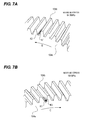
- FIGS. 7A and 7B are numerical value-attached perspective views illustrating maximum stress and calculation results of occurrence points of the maximum stress in the developing reduction gear 104, respectively. It indicates that stress becomes gradually higher in the order from a gray-painted portion K2 to a black-painted portion K1.
- FIG. 7A illustrates the calculation results when the developing reduction gear 104 rotates in the rotational direction (direction indicated by the arrow B) of this embodiment corresponding to FIGS. 6A to 6C .
- FIG. 7B illustrates the calculation results when the developing reduction gear 104 rotates in the rotational direction (direction indicated by the arrow C) corresponding to FIGS. 6D to 6F , which is reverse to the rotational direction of this embodiment.
- a stress value is expressed by the maximum principal stress. Even in any case, the maximum stress occurs in a tooth root in the vicinity of the front side 104a having the large torsional rigidity.
- the maximum stress value in this embodiment is 1, the maximum stress value during the rotation in the reverse direction (see FIG. 7B ) becomes 2.3.
- FIG. 8 is a cross-sectional view of a developing motor gear 105 and a developing reduction gear 104 according to a second embodiment.
- a configuration of the second embodiment is the same as that of the first embodiment except that a gradient of torsional rigidity in a tooth width direction M of the developing reduction gear 104 is provided, and the description of the same configuration will not be presented.
- the thickness of a rim 104c of the developing reduction gear 104 becomes gradually thinner from a front side 104a (one side) toward a rear side 104b (the other side) in the tooth width direction M.
- the gradient of the torsional rigidity in the tooth width direction M is formed to be large at the front side 104a and to be small at the rear side 104b.
- the torsional rigidity in the tooth width direction M of the developing reduction gear 104 becomes gradually smaller from the front side 104a (one side) toward the rear side 104b (the other side) in the tooth width direction M.
- the torsional rigidity in the tooth width direction M becomes gradually smaller from a thick side of the rim 104c toward a thin side of the rim 104c. For this reason, it is also considered that the torsional rigidity at the thin side of the rim 104c is smaller than the torsional rigidity at the thick side of the rim 104c.
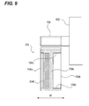
- FIG. 9 is a cross-sectional view illustrating a developing motor gear 105 and a developing reduction gear 104 according to a third embodiment in detail.
- a configuration of this embodiment is the same as that of the first embodiment except that a gradient of torsional rigidity in a tooth width direction M of the developing reduction gear 104 is provided, and the description of the same configuration will not be presented.
- the developing reduction gear 104 is formed with a web 104e between a boss 104d and a rim 104c.
- the web 104e is disposed substantially at the center in the tooth width direction M of the developing reduction gear 104.
- the web 104e is formed in a disk-like plate shape around the boss 106.
- a rib 104f radially extends from the boss 104d (this is the same as the configuration in FIG. 4B ) and protrudes toward a front side 104a from the web 104e (this is different from the configuration in FIG. 4B ) at the same time.
- the rib 104f is disposed at only the front side 104a (one side) in the tooth width direction M. For this reason, a gradient of torsional rigidity in the tooth width direction M is formed to be large at the front side 104a and to be small at a rear side 104b.
- the torsional rigidity in the tooth width direction M of the developing reduction gear 104 becomes gradually smaller from the front side 104a (one side) toward the rear side 104b (the other side) in the tooth width direction M.
- the torsional rigidity in the tooth width direction M becomes gradually smaller from a side disposed with the rib 104f toward a side not disposed with the rib 104f.
- the torsional rigidity in the tooth width direction M at the side not disposed with the rib 104f is smaller than the torsional rigidity in the tooth width direction M at the side disposed with the rib 104f.
- any one configuration of the first to third embodiments it is possible to suppress stress concentration on a gear tooth root even when the module is reduced compared to the related art.
- an image forming apparatus(50) that forms an image on a recording material
- the apparatus including: a first helical gear(105) and a second helical gear(104) that are engaged with each other; and a driving portion(102) that applies a driving force to the first helical gear(105), wherein at least one of the first helical gear(105) and the second helical gear(104) is a helical gear in which torsional rigidity in a tooth width direction(M) of one side end(104X1) in a width direction of the gear is larger than torsional rigidity in a tooth width direction(M) of the other side end(104X2), and wherein a twist direction of helical teeth and a rotational direction of the first helical gear(105) due to the driving portion(102) are set such that the other side end(104X2) is engaged earlier than the one side end(104X1).
Abstract
Description
- The present invention relates to an image forming apparatus such as a copying machine or a printer equipped with a function of forming an image on a recording material such as a sheet.
-
Japanese Patent Laid-Open No. 9-230657 - By this configuration, it is considered that variation in a position occurs due to a rotation fluctuation or vibration of an image preparing portion caused by a rotation fluctuation or vibration occurring at a gear engagement cycle and thus a periodic band-like uneven density called a banding image is prevented.
- However, the invention disclosed in
Japanese Patent Laid-Open No. 9-230657 - Under these circumstance, the inventors paid attention to the fact that a portion of an arm formed between the tooth surface and a rotation support portion is disposed at the center of a tooth width direction in the configuration illustrated in
FIG. 3 ofJapanese Patent Laid-Open No. 9-230657 - The present invention in its first aspect provides An image forming apparatus as specified in claim 1 to 8.
- Further features of the present invention will become apparent from the following description of exemplary embodiments with reference to the attached drawings.
-
-
FIG. 1 is a schematic cross-sectional view illustrating schematically an image forming apparatus according to the invention. -
FIG. 2A is a schematic diagram illustrating a state where motors are connected to a photosensitive drum and an intermediate belt unit, respectively, andFIG. 2B is a schematic diagram of a driving configuration of a developing device. -
FIG. 3 is a schematic diagram of a gear arrangement in the driving configuration of the developing device illustrated inFIG. 2B . -
FIGS. 4A and 4B are perspective views illustrating a developing motor gear and a developing reduction gear in detail. -
FIG. 5 is a cross-sectional view of the developing motor gear and the developing reduction gear. -
FIGS. 6A to 6F are perspective views illustrating calculation results of a contact state of teeth, respectively. -
FIGS. 7A and 7B are numerical value-attached perspective views illustrating maximum stress in a developing reduction gear and calculation results of occurrence points of the maximum stress. -
FIG. 8 is a cross-sectional view of a developing motor gear and a developing reduction gear according to a second embodiment. -
FIG. 9 is a cross-sectional view of a developing motor gear and a developing reduction gear according to a third embodiment. - Hereinafter, with reference to the drawings, embodiments of the invention will be exemplarily described in detail. However, dimensions, materials, shapes, and relative positions of components described in the embodiments are appropriately changed depending on structures and various conditions of apparatuses to which the invention is applied and therefore the scope of the invention is not intended to be limited thereto unless otherwise particularly specified. In each of the drawings, components denoted by the same reference numerals have the same structure or operation, and the duplication description thereof will not be appropriately presented.
-
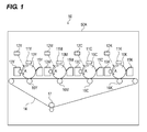
FIG. 1 is a schematic cross-sectional view illustrating schematically animage forming apparatus 50 according to the invention. In the following description, each of the stations denoted by reference numerals with Y, M, C, and K means member for yellow, magenta, cyan, and black, and these members will be described below by reference numerals without signs of Y, M, C, and K. Theimage forming apparatus 50 illustrated inFIG. 1 is an example of a full-color image forming apparatus (complex machine having all of copying machine, printer function, and FAX function). InFIG. 1 , theimage forming apparatus 50 has a plurality of image forming stations (four image forming stations in this embodiment) which are transversely juxtaposed with each other in an image forming apparatus body (hereinafter, referred to as an "apparatus body 50A"). - Each of the stations includes a drum-like electrophotographic photosensitive drum (referred to as a "photosensitive drum 10" in this embodiment) as an "image bearing member". In this embodiment, the photosensitive drums 10 sequentially bear color images of a yellow (Y) component, a magenta (M) component, a cyan (C) component, and a black (K) component, respectively. These photosensitive drums 10 are rotatably driven at a predetermined process speed in an arrow direction "A" (counterclockwise direction) by a drum motor which is not illustrated in the drawing.
- For example, a charging device 11, a scanner unit 12, a developing device 13, an
intermediate belt unit 14, and a cleaning device 15 are sequentially disposed around each of the photosensitive drums 10 according to a rotational direction of the photosensitive drum 10. The charging device 11 (charging means) is configured to uniformly charge the surface of the photosensitive drum 10. The scanner unit 12 (exposure means) is configured to irradiate the photosensitive drum 10 with a laser beam based on image information and form an electrostatic image on the photosensitive drum 10. - The developing device 13 as a "developing means" is configured to develop the electrostatic image formed on the surface of the photosensitive drum 10 with a toner and generate a developer image (toner image). The intermediate belt unit 14 (electrostatic transfer means) is configured to transfer the toner image on the photosensitive drum 10 onto a sheet. The cleaning device 15 (cleaning means) is configured to remove a transfer residual toner remaining on the surface of the photosensitive drum 10 after the transfer.
- Hereinafter, the image forming station for yellow (Y) out of four colors will be described as an example. A
photosensitive drum 10Y is uniformly subjected to a charging treatment by acharging device 11Y during a rotation process so as to have predetermined polarity and potential. Then, thephotosensitive drum 10Y is exposed to light by alaser scanner 12Y, whereby an electrostatic image of image information is formed on thephotosensitive drum 10Y. - Next, the electrostatic image formed on the
photosensitive drum 10Y is visualized by a developingdevice 15Y and thus a toner image is formed on thephotosensitive drum 10Y. Subsequently, the toner image formed on the photosensitive drum 10 is transferred onto theintermediate belt unit 14 by aprimary transfer roller 16Y. Thereafter, the toner image on theintermediate belt unit 14 is transferred onto a sheet or other output objects by asecondary transfer roller 17. Similar processes are performed on the image forming stations for other three colors (magenta (M), cyan (C), and black (K)). - A driving device of an image preparing portion which drives the photosensitive drum 10, the
intermediate belt unit 14, and the developing device 13 equipped with a driving transmission device, which is a feature of the invention, will be described below. -
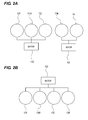
FIG. 2A is a schematic diagram illustrating a state wheremotors intermediate belt unit 14, respectively. As illustrated inFIG. 2A , thephotosensitive drums motor 100, and thephotosensitive drum 10K and theintermediate belt unit 14 are driven by themotor 101. -
FIG. 2B is a schematic diagram illustrating a state where amotor 102 is connected to the developing device 13. As illustrated inFIG. 2B , the developingdevices motor 102. -
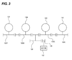
FIG. 3 is a schematic diagram of a gear arrangement in a driving configuration of the developing device 13 illustrated inFIG. 2B . As illustrated inFIG. 3 , the developing device 13 is driven by a developing drive gear 103 provided coaxially with a drive input position. A DC brushless motor is often used as themotor 102, which generally has a rotation speed from about 2000 to 3000 rpm in terms of efficiency. - The rotation speed of the developing device 13 to be often used is about 100 to 500 rpm, thereby being reduced by a gear ratio between a developing
reduction gear 104, a developingmotor gear 105, and the developing drive gear 103. As in this configuration, in a case where a plurality of rotating objects is rotated by one motor, a large load is concentrated on the developingreduction gear 104 compared with a configuration in which one rotation object is rotated by one motor. -
FIG. 4A is a perspective view illustrating the developingmotor gear 105 and the developingreduction gear 104 in detail.FIG. 4B is a view as seen from the back inFIG. 4A . Referring toFIGS. 4A and 4B , the shapes of the developingmotor gear 105 and the developingreduction gear 104 corresponding to the driving gear of this embodiment will be described below in detail. - The
motor 102 is provided as a "driving portion" which drives the developingmotor gear 105 of the developing device 13. The driving force of themotor 102 is transmitted to the developing device 13 through a driving transmission means. The developingmotor gear 105 as a "first helical gear" and the developingreduction gear 104 as a "second helical gear" are disposed to come in contact with each other, and the driving force is transmitted to the developingreduction gear 104 from the developingmotor gear 105. - In the case of being viewed from the above in
FIG. 4A , since the developingmotor gear 105 has teeth which are cut in a direction from a lower left toward an upper right, it is formed by right-twisted helical teeth. In addition, since the developingreduction gear 104 has teeth which are cut in a direction from a lower right toward an upper left, it is formed by left-twisted helical teeth. In this way, the helical gears coming in contact with each other can be obtained by a combination of the right-twisted teeth and the left-twisted teeth in a reverse direction. - As illustrated in
FIG. 4A , the developingmotor gear 105 is formed in such a manner of being directly subjected to gear cutting together with ametallic driving shaft 102X of themotor 102 as a "motor" which generates a driving force. Therefore, the developingmotor gear 105 is totally formed of a metal. - As illustrated in
FIG. 4B , the developingreduction gear 104 is engaged with the developingmotor gear 105. The developingreduction gear 104 includes arim 104c which is formed of a resin and has an outer circumference formed with teeth, aboss 104d which is the center of rotation of therim 104c (simultaneously, forming the center of rotation of the gear), and aweb 104e through which therim 104c and theboss 104d are connected to each other. - In addition, a
rib 104f and arib 104g protrude from the face of theweb 104e. Therib 104f radially extends in a radial fashion (in a radial ray fashion) (in a direction separated from theboss 104d) from theboss 104d for the purpose of reinforcement of the developingreduction gear 104. Therib 104g is concentrically disposed with respect to theboss 104d. Therib 104f is disposed with a predetermined distance from therim 104c so as to prevent tooth-face accuracy from deteriorating due to shrinkage during molding and is formed not to come in contact with therim 104c. -
FIG. 5 is a cross-sectional view of the developingmotor gear 105 and the developingreduction gear 104. Theweb 104e is provided on afront side 104a of the developingreduction gear 104. For this reason, a tooth width direction M of theweb 104e is positioned at a left end deviated from a center M1 in the tooth width direction M. Herein, the tooth width direction M refers to a thickness direction of the gear. - Therefore, a gradient of torsional rigidity in the tooth width direction M is formed to be large at the
front side 104a of the developingreduction gear 104 and to be small at arear side 104b thereof. That is, the torsional rigidity of developingreduction gear 104 in the tooth width direction M becomes gradually smaller from thefront side 104a (one side) toward therear side 104b (the other side) in the tooth width direction M. For this reason, the developingreduction gear 104 refers to a helical gear in which the torsional rigidity in the tooth width direction M of thefront side 104a (one side end) in the tooth width direction M of the developingreduction gear 104 is larger than the torsional rigidity in the tooth width direction of therear side 104b (the other side end). - In other words, the torsional rigidity in the tooth width direction M becomes gradually smaller from a side where the
web 104e is closer to the tooth width direction M toward a side where theweb 104e is not closer to the tooth width direction M. For this reason, it is said that torsional rigidity at the side where theweb 104e is not closer to the tooth width direction M is smaller than the torsional rigidity at the side where theweb 104e is closer to the tooth width direction M. At least one of the developingmotor gear 105 and the developingreduction gear 104 may be configured in this manner. - Returning back to
FIGS. 4A and 4B , the description will be made below. The developingmotor gear 105 rotates in a direction indicated by an arrow A, and the developingreduction gear 104 engaged with the developingmotor gear 105 rotates in a direction indicated by an arrow B. The helical gear has a property that comes in contact with the other gear to be engaged from an advancing side in the rotational direction. - That is, the helical gear sequentially comes in contact with the other gear to be engaged from an advancing helical tooth in the advancing direction of each rotating helical teeth. That is, since the developing
motor gear 105 is right-twisted and thus rotates in the direction indicated by the arrow A, a rear end 105X2 ofhelical teeth 105X rotates earlier than a front end 105X1 thereof in the direction indicated by the arrow A. In addition, since the developingreduction gear 104 is left-twisted and thus rotates in the direction indicated by the arrow B, a rear end 104X2 ofhelical teeth 104X rotates earlier than a front end 104X1 thereof in the direction indicated by the arrow B. Accordingly, the developingmotor gear 105 and the developingreduction gear 104 come in contact with the other gear to be engaged from the rear ends 105X2 and 104X2 advancing in the advancing direction, respectively. - In the configuration of this embodiment, the direction of the helical teeth is set such that the contact occurs from the
rear side 104b having the small torsional rigidity. That is, a twist direction of the helical teeth and the rotational direction of the developingmotor gear 105 due to themotor 102 are set such that the developingmotor gear 105 and the developingreduction gear 104 are engaged with each other in such a manner that the teeth come in contact with each other at the side (the other side in the tooth width direction) (the other side end) having the small torsional rigidity earlier than the side (one side in the tooth width direction) (one side end) having the large torsional rigidity. - A simulation experiment is performed to observe the contact state of the teeth of this embodiment configured as described above and to calculate the maximum value of tooth root stress. The simulation experiment is performed using Abaqus which is versatile software for non-linear structure analysis. The developing
motor gear 105 is a rigid body and the developingreduction gear 104 is an elastic body having a Young's modulus of 2200 MPa. A module of the gear is 0.4, a twist angle is 20°, a pressure angle is 20°, the number of teeth of the developingmotor gear 105 is 11, the number of teeth of the developingreduction gear 104 is 86, and a driving load is 0.8 N·m. In this way, the number of teeth of the developingmotor gear 105 is set to be smaller than the number of teeth of the developingreduction gear 104. -
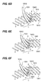
FIGS. 6A to 6F are perspective views illustrating calculation results of the contact state of the teeth when the developingreduction gear 104 rotates in the direction indicated by an arrow B and an arrow C. In order to make it easy to see the contact state, only the tooth surface of the developingmotor gear 105 is illustrated. In addition, the developingreduction gear 104 illustrated inFIGS. 6A to 6F looks like a spur gear in external appearance, but has the left-twisted helical teeth which are left-twisted with respect to the axial line as described above in fact.FIGS. 6A to 6F are enlarged diagrams of the actual helical teeth, respectively. - In
FIGS. 6A to 6F , a contact portion is indicated by a black-painted portion K. The developingreduction gear 104 rotates in the direction indicated by the arrow B in this order ofFIGS. 6A to 6C . As thehelical teeth 105X of the developingmotor gear 105 rotate, the developingmotor gear 105 continues to come in sequential contact with the developingreduction gear 104 from the rear end 105X2 side which is the advancing side of the helical teeth. Then, the contact area between the developingmotor gear 105 and the developingreduction gear 104 shifts from the rear end 104X2 of the developingreduction gear 104 to the front end 104X1. In addition, it is understood that threehelical teeth 105X of the developingmotor gear 105 always come in contact with the developingreduction gear 104 during the rotation. -
FIGS. 6D to 6F are illustrated in comparison with this embodiment and are perspective views illustrating calculation results of a contact state of teeth when the developingreduction gear 104 rotates in the direction indicated by an arrow C which is a direction reverse to the direction illustrated inFIGS. 6A to 6C , respectively. Since thehelical teeth 105X of the developingmotor gear 105 rotate in a reverse direction, the advancing direction of the helical teeth is also reverse and thus the developingmotor gear 105 continues to come in sequential contact with the developingreduction gear 104 from the front end 105X1 side. Then, the number of thehelical teeth 105X of the developingmotor gear 105, which always come in contact with the developingreduction gear 104 during the rotation, is reduced to two. - Comparing these two examples with each other, in the rotational direction of this embodiment, since the developing
motor gear 105 comes in contact with the developingreduction gear 104 from therear side 104b having the small torsional rigidity, and the developingmotor gear 105 comes in contact with a deformable portion of the developingreduction gear 104, the number of the teeth of the developingmotor gear 105 coming in contact with the developingreduction gear 104 at all times increases. Meanwhile, in the rotation in the reverse direction, since the developingmotor gear 105 comes in contact with the developingreduction gear 104 from thefront side 104a having the large torsional rigidity, and the developingmotor gear 105 comes in contact with a hardly deformable portion of the developingreduction gear 104, the number of the teeth of the developingmotor gear 105 coming in contact with the developingreduction gear 104 at all times reduces. -
FIGS. 7A and 7B are numerical value-attached perspective views illustrating maximum stress and calculation results of occurrence points of the maximum stress in the developingreduction gear 104, respectively. It indicates that stress becomes gradually higher in the order from a gray-painted portion K2 to a black-painted portion K1.FIG. 7A illustrates the calculation results when the developingreduction gear 104 rotates in the rotational direction (direction indicated by the arrow B) of this embodiment corresponding toFIGS. 6A to 6C .FIG. 7B illustrates the calculation results when the developingreduction gear 104 rotates in the rotational direction (direction indicated by the arrow C) corresponding toFIGS. 6D to 6F , which is reverse to the rotational direction of this embodiment. - A stress value is expressed by the maximum principal stress. Even in any case, the maximum stress occurs in a tooth root in the vicinity of the
front side 104a having the large torsional rigidity. When the maximum stress value in this embodiment (seeFIG. 7A ) is 1, the maximum stress value during the rotation in the reverse direction (seeFIG. 7B ) becomes 2.3. - In this embodiment (see
FIG. 7A ), since the contact number of the teeth, that is, the contact area to which the load is applied becomes larger when the developingreduction gear 104 rotates in the direction indicated by the arrow B, the stress value becomes smaller so as to relatively reduce the amount of deformation of each tooth and the maximum stress also becomes smaller, which is 84.5 MPa. Whereas, in the comparative example (seeFIG. 7B ), since the contact number of the teeth, that is, the contact area to which the load is applied becomes smaller when the developingreduction gear 104 rotates in the direction indicated by the arrow C, the stress value becomes larger so as to relatively increase the amount of deformation of each tooth and the maximum stress also becomes larger, which is 194 MPa. - According to this embodiment, when high loads are transmitted with a small module, since the rigidity increases to ensure strength and thus deterioration in accuracy of the tooth surface is not caused by the shrinkage during molding, it is possible to provide a driving configuration in which a high-quality image not having a banding image can be output.
-
FIG. 8 is a cross-sectional view of a developingmotor gear 105 and a developingreduction gear 104 according to a second embodiment. A configuration of the second embodiment is the same as that of the first embodiment except that a gradient of torsional rigidity in a tooth width direction M of the developingreduction gear 104 is provided, and the description of the same configuration will not be presented. - The thickness of a
rim 104c of the developingreduction gear 104 becomes gradually thinner from afront side 104a (one side) toward arear side 104b (the other side) in the tooth width direction M. For this reason, the gradient of the torsional rigidity in the tooth width direction M is formed to be large at thefront side 104a and to be small at therear side 104b. Thus, the torsional rigidity in the tooth width direction M of the developingreduction gear 104 becomes gradually smaller from thefront side 104a (one side) toward therear side 104b (the other side) in the tooth width direction M. In other words, the torsional rigidity in the tooth width direction M becomes gradually smaller from a thick side of therim 104c toward a thin side of therim 104c. For this reason, it is also considered that the torsional rigidity at the thin side of therim 104c is smaller than the torsional rigidity at the thick side of therim 104c. -
FIG. 9 is a cross-sectional view illustrating a developingmotor gear 105 and a developingreduction gear 104 according to a third embodiment in detail. A configuration of this embodiment is the same as that of the first embodiment except that a gradient of torsional rigidity in a tooth width direction M of the developingreduction gear 104 is provided, and the description of the same configuration will not be presented. - In this embodiment, the developing
reduction gear 104 is formed with aweb 104e between aboss 104d and arim 104c. Theweb 104e is disposed substantially at the center in the tooth width direction M of the developingreduction gear 104. Theweb 104e is formed in a disk-like plate shape around the boss 106. - On the premise of this configuration, a
rib 104f radially extends from theboss 104d (this is the same as the configuration inFIG. 4B ) and protrudes toward afront side 104a from theweb 104e (this is different from the configuration inFIG. 4B ) at the same time. In this way, therib 104f is disposed at only thefront side 104a (one side) in the tooth width direction M. For this reason, a gradient of torsional rigidity in the tooth width direction M is formed to be large at thefront side 104a and to be small at arear side 104b. - Thus, the torsional rigidity in the tooth width direction M of the developing
reduction gear 104 becomes gradually smaller from thefront side 104a (one side) toward therear side 104b (the other side) in the tooth width direction M. In other words, the torsional rigidity in the tooth width direction M becomes gradually smaller from a side disposed with therib 104f toward a side not disposed with therib 104f. For this reason, it is also considered that the torsional rigidity in the tooth width direction M at the side not disposed with therib 104f is smaller than the torsional rigidity in the tooth width direction M at the side disposed with therib 104f. - According to any one configuration of the first to third embodiments, it is possible to suppress stress concentration on a gear tooth root even when the module is reduced compared to the related art.
- While the present invention has been described with reference to exemplary embodiments, it is to be understood that the invention is not limited to the disclosed exemplary embodiments. The scope of the following claims is to be accorded the broadest interpretation so as to encompass all such modifications and equivalent structures and functions.
- Provided is an image forming apparatus(50) that forms an image on a recording material, the apparatus including: a first helical gear(105) and a second helical gear(104) that are engaged with each other; and a driving portion(102) that applies a driving force to the first helical gear(105), wherein at least one of the first helical gear(105) and the second helical gear(104) is a helical gear in which torsional rigidity in a tooth width direction(M) of one side end(104X1) in a width direction of the gear is larger than torsional rigidity in a tooth width direction(M) of the other side end(104X2), and wherein a twist direction of helical teeth and a rotational direction of the first helical gear(105) due to the driving portion(102) are set such that the other side end(104X2) is engaged earlier than the one side end(104X1).
Claims (8)
- An image forming apparatus(50) that forms an image on a recording material, the image forming apparatus comprising:a first helical gear(105) and a second helical gear(104) that are engaged with each other; anda driving portion (102) that applies a driving force to the first helical gear(105),wherein at least one of the first helical gear(105) and the second helical gear(104) is a helical gear in which torsional rigidity in a tooth width direction(M) of one side end(104X1) in a width direction of the gear is larger than torsional rigidity in a tooth width direction(M) of the other side end(104X2), andwherein a twist direction of helical teeth and a rotational direction of the first helical gear(105) due to the driving portion(102) are set such that the other side end(104X2) is engaged earlier than the one side end(104X1).
- The image forming apparatus(50) according to claim 1, wherein at least one of the second helical gear(104) and the first helical gear(105) includes a rim(104c) that has an outer circumference formed with teeth, a boss(104d) that is the center of rotation of the rim(104c), and a web(104e) through which the rim(104c) and the boss(104d) are connected to each other, a position in a tooth width direction(M) of the web(104e) is disposed at a position deflected from the center of the tooth width direction(M), and torsional rigidity at a side where the web(104e) is not closer to the tooth width direction(M) is smaller than torsional rigidity at a side where the web is closer to the tooth width direction(M).
- The image forming apparatus(50) according to claim 2, wherein at least one of the second helical gear(104) and the first helical gear(105) includes the rim that has an outer circumference formed with teeth, the boss(104d) that is the center of rotation of the rim(104c), and the web(104e) through which the rim(104c) and the boss(104d) are connected to each other, a thickness of the rim(104c) becomes thinner from one side to the other side in the tooth width direction(M), and torsional rigidity at a thin side of the rim(104c) is smaller than torsional rigidity at a thick side of the rim(104c).
- The image forming apparatus(50) according to claim 2, wherein the second helical gear(104) includes a plurality of ribs that protrudes in the tooth width direction(M) from a face of the web(104e) and radially extends around the boss(104d), the rib(104f) is disposed at only one side when viewed from the center in the tooth width direction(M) and is not disposed at the other side when viewed from the center in the tooth width direction(M), and torsional rigidity in the tooth width direction(M) at the side not disposed with the rib(104f) is smaller than torsional rigidity in the tooth width direction(M) at the side disposed with the rib(104f).
- The image forming apparatus(50) according to claim 1, wherein the second helical gear(104) is formed of a resin and the first helical gear(105) is formed of a metal.
- The image forming apparatus(50) according to claim 5, wherein the number of teeth of the first helical gear(105) is set to be smaller than the number of teeth of the second helical gear(104).
- The image forming apparatus(50) according to claim 6, wherein the first helical gear(105) is subjected to gear cutting together with a driving shaft(102X) of a motor(102) which generates the driving force.
- The image forming apparatus(50) according to claim 7, further comprising:an image bearing member(10Y,10M,10C,10K); anda developing means(13Y,13M,13C,13K) that develops an electrostatic image on a surface of the image bearing member(10Y,10M,10C,10K) with a toner,wherein the motor(102) is the driving portion (102) that drives the developing means(13Y,13M,13C,13K).
Applications Claiming Priority (1)
| Application Number | Priority Date | Filing Date | Title |
|---|---|---|---|
| JP2014221347A JP6494246B2 (en) | 2014-10-30 | 2014-10-30 | Image forming apparatus |
Publications (1)
| Publication Number | Publication Date |
|---|---|
| EP3015923A1 true EP3015923A1 (en) | 2016-05-04 |
Family
ID=54365070
Family Applications (1)
| Application Number | Title | Priority Date | Filing Date |
|---|---|---|---|
| EP15192111.1A Withdrawn EP3015923A1 (en) | 2014-10-30 | 2015-10-29 | Image forming apparatus |
Country Status (4)
| Country | Link |
|---|---|
| US (2) | US9535365B2 (en) |
| EP (1) | EP3015923A1 (en) |
| JP (1) | JP6494246B2 (en) |
| CN (2) | CN105573091A (en) |
Families Citing this family (5)
| Publication number | Priority date | Publication date | Assignee | Title |
|---|---|---|---|---|
| JP6555210B2 (en) * | 2016-08-09 | 2019-08-07 | トヨタ自動車株式会社 | Gear mechanism and manufacturing method thereof |
| JP2020154077A (en) * | 2019-03-19 | 2020-09-24 | ブラザー工業株式会社 | Image forming device |
| JP2021179581A (en) | 2020-05-15 | 2021-11-18 | キヤノン株式会社 | Image forming apparatus |
| JP2021179582A (en) | 2020-05-15 | 2021-11-18 | キヤノン株式会社 | Frame body of image forming apparatus and image forming apparatus |
| JP2021179580A (en) | 2020-05-15 | 2021-11-18 | キヤノン株式会社 | Image forming apparatus |
Citations (7)
| Publication number | Priority date | Publication date | Assignee | Title |
|---|---|---|---|---|
| JPH0328565A (en) * | 1989-06-24 | 1991-02-06 | Nissan Motor Co Ltd | Noise reducing gear |
| JPH04351365A (en) * | 1991-05-30 | 1992-12-07 | Canon Inc | Plastic molded gear, drive device, and image forming device |
| JPH086437A (en) * | 1994-06-17 | 1996-01-12 | Nec Corp | Photosensitive drum driving gear of electrophotographic device |
| JPH09230657A (en) | 1996-02-26 | 1997-09-05 | Canon Inc | Image forming device, process cartridge and gear |
| US20030131678A1 (en) * | 2002-01-15 | 2003-07-17 | Koji Noguchi | Injection molded resin gear, injection molded resin rotating body, and injection molded article |
| GB2397136A (en) * | 2003-01-10 | 2004-07-14 | Gcc Man Ltd | A toner cartridge |
| JP2006242325A (en) * | 2005-03-04 | 2006-09-14 | Enplas Corp | Gear and gearing device |
Family Cites Families (18)
| Publication number | Priority date | Publication date | Assignee | Title |
|---|---|---|---|---|
| JPH0399264U (en) * | 1990-01-31 | 1991-10-16 | ||
| JPH0869239A (en) * | 1994-08-31 | 1996-03-12 | Canon Inc | Image carrier, process cartridge and image forming device |
| US6752035B2 (en) * | 2000-04-10 | 2004-06-22 | Enplas Corporation | Gear made of resin, image forming device having the resin gear and rotary gearing device made of resin |
| US6708013B2 (en) * | 2001-06-14 | 2004-03-16 | Seiko Epson Corporation | Color image forming apparatus |
| JP2005300703A (en) * | 2004-04-08 | 2005-10-27 | Ricoh Co Ltd | Image forming apparatus |
| JP2006301389A (en) * | 2005-04-22 | 2006-11-02 | Ricoh Co Ltd | Mechanical reduction gear and electrophotographic image forming apparatus |
| JP2006329243A (en) * | 2005-05-24 | 2006-12-07 | Ricoh Co Ltd | Helical gear and its forming die |
| JP4720385B2 (en) * | 2005-09-06 | 2011-07-13 | ブラザー工業株式会社 | Image forming apparatus and image forming unit driving apparatus |
| JP4749137B2 (en) * | 2005-11-30 | 2011-08-17 | 株式会社リコー | Component life management apparatus and image forming system |
| JP4618807B2 (en) * | 2006-06-07 | 2011-01-26 | 株式会社エンプラス | Injection molded resin gear |
| JP4618808B2 (en) * | 2006-09-14 | 2011-01-26 | 株式会社エンプラス | Resin face gear and injection mold for this resin face gear |
| JP2011090040A (en) * | 2009-10-20 | 2011-05-06 | Brother Industries Ltd | Image forming apparatus |
| JP5623164B2 (en) * | 2010-07-14 | 2014-11-12 | キヤノン株式会社 | Image forming apparatus |
| JP5408173B2 (en) * | 2011-03-31 | 2014-02-05 | ブラザー工業株式会社 | Image forming apparatus |
| JP5853553B2 (en) * | 2011-09-30 | 2016-02-09 | ブラザー工業株式会社 | Rotating body unit |
| US8934815B2 (en) | 2012-11-02 | 2015-01-13 | Ricoh Company, Ltd. | Gear transmission device and image forming apparatus including the same |
| JP6146603B2 (en) * | 2013-03-01 | 2017-06-14 | 株式会社リコー | GEAR TRANSMISSION DEVICE, PROCESS UNIT HAVING THE DEVICE, AND IMAGE FORMING DEVICE |
| JP5865871B2 (en) * | 2013-06-19 | 2016-02-17 | 京セラドキュメントソリューションズ株式会社 | Drive device |
-
2014
- 2014-10-30 JP JP2014221347A patent/JP6494246B2/en active Active
-
2015
- 2015-10-26 US US14/922,336 patent/US9535365B2/en not_active Ceased
- 2015-10-29 EP EP15192111.1A patent/EP3015923A1/en not_active Withdrawn
- 2015-10-30 CN CN201510737257.XA patent/CN105573091A/en active Pending
- 2015-10-30 CN CN201910970667.7A patent/CN110658706A/en active Pending
-
2018
- 2018-12-27 US US16/233,720 patent/USRE49143E1/en active Active
Patent Citations (7)
| Publication number | Priority date | Publication date | Assignee | Title |
|---|---|---|---|---|
| JPH0328565A (en) * | 1989-06-24 | 1991-02-06 | Nissan Motor Co Ltd | Noise reducing gear |
| JPH04351365A (en) * | 1991-05-30 | 1992-12-07 | Canon Inc | Plastic molded gear, drive device, and image forming device |
| JPH086437A (en) * | 1994-06-17 | 1996-01-12 | Nec Corp | Photosensitive drum driving gear of electrophotographic device |
| JPH09230657A (en) | 1996-02-26 | 1997-09-05 | Canon Inc | Image forming device, process cartridge and gear |
| US20030131678A1 (en) * | 2002-01-15 | 2003-07-17 | Koji Noguchi | Injection molded resin gear, injection molded resin rotating body, and injection molded article |
| GB2397136A (en) * | 2003-01-10 | 2004-07-14 | Gcc Man Ltd | A toner cartridge |
| JP2006242325A (en) * | 2005-03-04 | 2006-09-14 | Enplas Corp | Gear and gearing device |
Also Published As
| Publication number | Publication date |
|---|---|
| JP6494246B2 (en) | 2019-04-03 |
| CN110658706A (en) | 2020-01-07 |
| CN105573091A (en) | 2016-05-11 |
| US9535365B2 (en) | 2017-01-03 |
| USRE49143E1 (en) | 2022-07-19 |
| JP2016089863A (en) | 2016-05-23 |
| US20160124345A1 (en) | 2016-05-05 |
Similar Documents
| Publication | Publication Date | Title |
|---|---|---|
| USRE49143E1 (en) | Image forming apparatus | |
| CN1199089C (en) | Picture forming apparatus and driver of picture forming mechanism thereof | |
| US8585537B2 (en) | Driving device and image forming apparatus | |
| JP2015178895A (en) | Drive transmission device and image forming device | |
| JP2007011093A (en) | Drive connection mechanism and image forming apparatus having the mechanism | |
| JP5705344B2 (en) | Image forming apparatus | |
| JP2006301389A (en) | Mechanical reduction gear and electrophotographic image forming apparatus | |
| JP2016114127A (en) | Driving power transmission device | |
| JP2010019271A (en) | Planetary differential gear reduction gear and image forming device | |
| JP5999424B2 (en) | Drive transmission device and image forming apparatus | |
| JP2020003072A (en) | Image formation apparatus | |
| JP6591102B2 (en) | Image forming apparatus | |
| JP2005076784A (en) | Driving device and image forming device using the same | |
| US9223282B2 (en) | Image forming apparatus | |
| US20160223977A1 (en) | Driving force transmission device and image forming apparatus using the same | |
| EP1975736A2 (en) | Color image forming apparatus and image forming unit thereof | |
| JP2004360923A (en) | Method of application of reduction gear made of resin | |
| CN204287746U (en) | A kind of handle box | |
| US9752651B2 (en) | Driving apparatus having improved engagement | |
| JP6398933B2 (en) | Drive transmission mechanism and image forming apparatus having the same | |
| JP6016357B2 (en) | Gear and image forming apparatus | |
| JP2012092936A (en) | Planetary gear speed reducer and image forming device | |
| JP5262427B2 (en) | Rotating body driving device, image forming apparatus, rotating body drive control method, and computer program | |
| JP2016173112A (en) | Helical gear drive transmission device, and image forming apparatus | |
| JP2008052253A (en) | Image forming apparatus |
Legal Events
| Date | Code | Title | Description |
|---|---|---|---|
| PUAI | Public reference made under article 153(3) epc to a published international application that has entered the european phase |
Free format text: ORIGINAL CODE: 0009012 |
|
| AK | Designated contracting states |
Kind code of ref document: A1 Designated state(s): AL AT BE BG CH CY CZ DE DK EE ES FI FR GB GR HR HU IE IS IT LI LT LU LV MC MK MT NL NO PL PT RO RS SE SI SK SM TR |
|
| AX | Request for extension of the european patent |
Extension state: BA ME |
|
| 17P | Request for examination filed |
Effective date: 20161104 |
|
| RBV | Designated contracting states (corrected) |
Designated state(s): AL AT BE BG CH CY CZ DE DK EE ES FI FR GB GR HR HU IE IS IT LI LT LU LV MC MK MT NL NO PL PT RO RS SE SI SK SM TR |
|
| 17Q | First examination report despatched |
Effective date: 20190722 |
|
| STAA | Information on the status of an ep patent application or granted ep patent |
Free format text: STATUS: THE APPLICATION HAS BEEN WITHDRAWN |
|
| 18W | Application withdrawn |
Effective date: 20200527 |