EP3015835A1 - A method and a system for determining the operating temperature of a cell of an electric charge accumulator assembly without physical temperature sensors, particularly for electric or hybrid motor vehicles - Google Patents
A method and a system for determining the operating temperature of a cell of an electric charge accumulator assembly without physical temperature sensors, particularly for electric or hybrid motor vehicles Download PDFInfo
- Publication number
- EP3015835A1 EP3015835A1 EP15191733.3A EP15191733A EP3015835A1 EP 3015835 A1 EP3015835 A1 EP 3015835A1 EP 15191733 A EP15191733 A EP 15191733A EP 3015835 A1 EP3015835 A1 EP 3015835A1
- Authority
- EP
- European Patent Office
- Prior art keywords
- cell
- temperature
- cells
- charge
- accumulator assembly
- Prior art date
- Legal status (The legal status is an assumption and is not a legal conclusion. Google has not performed a legal analysis and makes no representation as to the accuracy of the status listed.)
- Granted
Links
Images


Classifications
-
- G—PHYSICS
- G01—MEASURING; TESTING
- G01K—MEASURING TEMPERATURE; MEASURING QUANTITY OF HEAT; THERMALLY-SENSITIVE ELEMENTS NOT OTHERWISE PROVIDED FOR
- G01K7/00—Measuring temperature based on the use of electric or magnetic elements directly sensitive to heat ; Power supply therefor, e.g. using thermoelectric elements
- G01K7/42—Circuits effecting compensation of thermal inertia; Circuits for predicting the stationary value of a temperature
- G01K7/427—Temperature calculation based on spatial modeling, e.g. spatial inter- or extrapolation
-
- H—ELECTRICITY
- H01—ELECTRIC ELEMENTS
- H01M—PROCESSES OR MEANS, e.g. BATTERIES, FOR THE DIRECT CONVERSION OF CHEMICAL ENERGY INTO ELECTRICAL ENERGY
- H01M10/00—Secondary cells; Manufacture thereof
- H01M10/42—Methods or arrangements for servicing or maintenance of secondary cells or secondary half-cells
- H01M10/48—Accumulators combined with arrangements for measuring, testing or indicating the condition of cells, e.g. the level or density of the electrolyte
- H01M10/486—Accumulators combined with arrangements for measuring, testing or indicating the condition of cells, e.g. the level or density of the electrolyte for measuring temperature
-
- H—ELECTRICITY
- H01—ELECTRIC ELEMENTS
- H01M—PROCESSES OR MEANS, e.g. BATTERIES, FOR THE DIRECT CONVERSION OF CHEMICAL ENERGY INTO ELECTRICAL ENERGY
- H01M10/00—Secondary cells; Manufacture thereof
- H01M10/42—Methods or arrangements for servicing or maintenance of secondary cells or secondary half-cells
- H01M10/48—Accumulators combined with arrangements for measuring, testing or indicating the condition of cells, e.g. the level or density of the electrolyte
- H01M10/482—Accumulators combined with arrangements for measuring, testing or indicating the condition of cells, e.g. the level or density of the electrolyte for several batteries or cells simultaneously or sequentially
-
- G—PHYSICS
- G01—MEASURING; TESTING
- G01K—MEASURING TEMPERATURE; MEASURING QUANTITY OF HEAT; THERMALLY-SENSITIVE ELEMENTS NOT OTHERWISE PROVIDED FOR
- G01K2205/00—Application of thermometers in motors, e.g. of a vehicle
-
- G—PHYSICS
- G01—MEASURING; TESTING
- G01K—MEASURING TEMPERATURE; MEASURING QUANTITY OF HEAT; THERMALLY-SENSITIVE ELEMENTS NOT OTHERWISE PROVIDED FOR
- G01K2217/00—Temperature measurement using electric or magnetic components already present in the system to be measured
-
- Y—GENERAL TAGGING OF NEW TECHNOLOGICAL DEVELOPMENTS; GENERAL TAGGING OF CROSS-SECTIONAL TECHNOLOGIES SPANNING OVER SEVERAL SECTIONS OF THE IPC; TECHNICAL SUBJECTS COVERED BY FORMER USPC CROSS-REFERENCE ART COLLECTIONS [XRACs] AND DIGESTS
- Y02—TECHNOLOGIES OR APPLICATIONS FOR MITIGATION OR ADAPTATION AGAINST CLIMATE CHANGE
- Y02E—REDUCTION OF GREENHOUSE GAS [GHG] EMISSIONS, RELATED TO ENERGY GENERATION, TRANSMISSION OR DISTRIBUTION
- Y02E60/00—Enabling technologies; Technologies with a potential or indirect contribution to GHG emissions mitigation
- Y02E60/10—Energy storage using batteries
Definitions
- the known external temperature of at least one cell detected by means of at least one physical temperature sensor connected to the cell or a set of cells.
- the number of physical sensors is advantageously smaller than the number of cells.
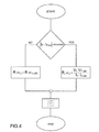
- the method for determining the internal resistance performed by the module for determining the internal resistance, IRE is described in greater detail with reference to Figure 4 . It is designed to estimate the internal resistance of a single cell R_int x , as a function of the variation in current detected during a sampling period. If this variation - indicated in the figure by the difference between the present current I y and the current detected at the previous sampling time I y_old - is greater (in terms of absolute value) than a predetermined threshold, the internal resistance of the single cell is estimated as being the ratio between the voltage differential (V x - V x_old ) and the current differential (I y - I y_old ). If this variation is less than said predetermined threshold, the internal resistance of the single cell is estimated to be unchanged compared to the previously calculated value.
- the resistance values thus obtained are filtered through a low-pass filter which has the function of limiting the pass-band of the signal, adapting it to the band of the current differential signal, in order to determine the resistance value R_int x input to the state of charge estimator module SOCE and to the temperature estimator module TE.
Landscapes
- Engineering & Computer Science (AREA)
- Manufacturing & Machinery (AREA)
- Chemical & Material Sciences (AREA)
- Chemical Kinetics & Catalysis (AREA)
- Electrochemistry (AREA)
- General Chemical & Material Sciences (AREA)
- Physics & Mathematics (AREA)
- General Physics & Mathematics (AREA)
- Secondary Cells (AREA)
Abstract
- providing a reference model of a cell, representative of the evolution over time of a relationship between the internal electrical resistance of the cell and the cell temperature, depending on the state of charge;
- determining the real internal electrical resistance of a cell of an accumulator assembly;
- estimating the state of charge of the cell;
- estimating the ageing of the cell; and
- determining an estimated operating temperature of the cell from the determined value of the real internal electrical resistance of the cell and the estimated state of charge, depending on the degree of ageing of the cell, by comparison with the reference model.
Description
- The present invention relates to electric charge accumulators, such as in particular the batteries for electric or hybrid vehicles, and specifically to determination of the operating temperature of the single cells in an electric charge accumulator assembly.
- Even more specifically, the invention relates to a method and a system for determining the operating temperature of each single cell of an electric charge accumulator assembly.
- In automotive applications, in particular for electrically driven or hybrid vehicles in which the electric energy stored in an accumulator assembly is also used for traction, in a continuous or discontinuous manner, it is necessary to have available accumulator systems with nominal voltages ranging from 48 V to 500 V and nominal capacities typically of between 500 Wh and several tens of kWh.
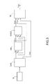
- An electrical circuit diagram of on-board accumulator assembly, more commonly known as a battery pack, is shown in
Figure 1 . The accumulator - which is indicated by A - comprises a plurality of electrochemical cells C, typically lithium ion cells, which are similar to each other and interconnected in a series and parallel configuration designed to provide the desired voltage and capacitance. - In the configuration shown by way of example in
Figure 1 the electrochemical cells C of the accumulator assembly A are arranged in a plurality of strings which are parallel to each other and each of which is formed by a plurality of cells connected in series and organized in a set of modules. - The accumulator assembly A is controlled by a battery management system comprising separate subsystems for managing the single modules of electrochemical cells, each of which includes:
- a circuit for acquiring the voltage across the single cells;
- a circuit for balancing the charge among the single cells;
- a plurality of temperature sensors adapted to measure the temperature of the cells in the module; and
- optionally a sensor for measuring the current supplied by the module, which may be common to several modules or to the entire accumulator assembly.
-
Figure 2 shows a subsystem for managing a module (BMC, Battery Management Controller) of similar cells C, which includes for each cell Cx a circuit OA1 for acquiring the voltage Vx across the cell and a circuit OA2 for acquiring the temperature T_Cx from a temperature sensor, for example a thermistor of the NTC type. - Knowledge of the temperature of each cell constitutes important information for correct management of said cell and the entire accumulator assembly. Knowledge of the temperature of the cells, together with knowledge of other characteristic electric parameters such as the voltage across the cells, is necessary for estimating the state of charge of the cells and for correct management and protection thereof in order to avoid triggering secondary chemical/physical processes which would result in a deterioration in their performance and their working life over time. In particular knowing the temperature and the value of the internal resistance, which can be deduced from the known voltage which establishes across the cells and the current supplied by each cell module, is useful for determining the State of Charge (SOC) and the State of Health (SOH) of the cell. The known temperature is then used in the operations for thermal management in general for protection of the cells and the accumulator assembly. In fact, a cell has an optimum performance if it is made to work at a predetermined operating temperature, determined by the current supplied and influenced by the cooling system associated with the accumulator assembly. By determining as precisely as possible the temperature of each cell it is possible to drive the cooling system associated with the accumulator assembly so as to maintain the desired operating temperature.
- Theoretically, if the accumulator assembly is assembled correctly, the average cell temperature is the same for all the cells. However, a lack of uniformity between the temperatures of the cells may arise depending on the physical design of the single cells, the operating environment and the connection of the cell modules to the associated cooling system.
- For this reason it is desirable to know the progression over time of the operating temperature of each single electrochemical cell of the accumulator assembly.
- It is known in the art to acquire the temperature of the single cells by means of physical sensors singly associated with the cells or with sets of cells. The number of sensors normally present in the battery packs is therefore relatively high, this resulting in additional costs, the correct location not being able to be easily determined since the battery pack is a compact assembly which does have free spaces for housing such sensors, and the high number of sensors increases significantly the probability of electrical faults. Moreover, the cell temperature detected by means of physical sensors is the external temperature of the cell, but not the real temperature of the dielectric material inside the cell, the chemical/physical properties of which are subject to alterations depending on this temperature. In addition, the temperature information acquired by external sensors constitutes a temperature measurement which is delayed compared to the real temperature inside the cell, and more generally a lower average value of the real temperature.
-
US 2012/0256569 describes a control device for a vehicle battery, comprising a battery control circuit which includes a unit for diagnosis of the internal temperature of the battery connected to a unit for estimating the internal temperature of the battery and a unit for calculating the internal resistance of the battery. The diagnosis unit receives a value indicating the superficial temperature of the battery and - from the unit for estimating the internal temperature of the battery - the estimated value of the internal temperature of the battery. The diagnosis unit receives, moreover, from the unit for calculating the internal resistance of the battery, the value of the aforementioned internal resistance calculated as a function of the battery voltage and current. The estimated value of the internal temperature of the battery is obtained as an average of the estimated values of the internal temperatures of the battery cells, which are determined from the surface temperatures of the battery cells, the temperature of the environment surrounding the battery and the rate of the cooling fluid. - The object of the present invention is to provide a satisfactory solution to the problem of determining the temperature of the single cells of an accumulator assembly, avoiding the drawbacks of the prior art. In particular, the object of the invention is to provide a method for determining more precisely the temperature of a single cell of an accumulator assembly and - at the same time - to reduce drastically, to the point even of eliminating, the need to install physical sensors for sensing the temperature of the cells, therefore reducing the costs and the complexity of the battery management system and increasing its reliability.
- According to the present invention this object is achieved by means of a method for determining the operating temperature of a cell of an electric charge accumulator assembly having the characteristic features mentioned in
Claim 1. - Particular embodiments form the subject of the dependent claims, the contents of which are to be understood as forming an integral or complementary part of the present description.
- The invention relates furthermore to a system for determining the operating temperature of a cell of an electric charge accumulator assembly as claimed.
- In short, the present invention is based on the principle of determining dynamically the temperature of a cell of an electric charge accumulator assembly without using physical temperature sensors connected to the cell, or limiting significantly the number thereof compared to the total number of cells of the accumulator assembly, and estimating indirectly the internal temperature of the cell from the measurement of intrinsic electrical parameters of the cell, representing its internal resistance, and from knowledge of the ageing of the cell. Ageing of the cell may be estimated by means of variation of the electrical parameters, such as the resistance and the internal capacitance of a reference model of the cell, or by means of a heuristic algorithm based on time counters. By means of a preliminary identification process it is possible to provide a reference model representing the evolution over time of a relationship between the intrinsic electrical parameters of the cell and the internal temperature of the cell.
- The known temperature of the cooling fluid represents an estimate of the cell temperature under static conditions of non-use of the accumulator assembly. Under dynamic conditions of use of the accumulator assembly the known temperature of the cooling fluid is lower than the real temperature of the single cells. However, knowledge of the average temperature of the cooling fluid may be used to provide a first estimate of the internal temperature of the cell. Advantageously, according to this approach, the accumulator assembly may not have physical temperature sensors connected to the cell.
- Alternatively, in order to obtain a first estimate of the internal temperature of the cell, it is possible to use the known external temperature of at least one cell, detected by means of at least one physical temperature sensor connected to the cell or a set of cells. Preferably, the number of physical sensors is advantageously smaller than the number of cells.
- Advantageously, with the system and the method according to the invention it is possible to obtain an increase in the reliability and a reduction of the costs depending on the physical temperature sensors associated with the single cells, the corresponding wiring and the necessary system for acquisition of the signals.
- Even more advantageously, with the system and the method according to the invention it is possible to determine the temperature of the single cells more rapidly and with a comparable precision compared with known systems including physical temperature sensors associated with the single cells.
- Further characteristic features and advantages of the invention will be described more fully in the detailed description below of an embodiment thereof, provided by way of a non-limiting example, with reference to the attached drawings in which:
-
Figure 1 shows a schematic circuit diagram of a known accumulator assembly, or battery pack, comprising a plurality of electrochemical cells; -
Figure 2 shows a schematic circuit diagram of a subsystem for managing a cell module of an accumulator assembly (BMC, Battery Management Controller); -
Figure 3 shows a block diagram of a system for determining the temperature according to the invention; -
Figure 4 is a flow diagram of the steps of a method for estimating the internal resistance carried out by the model for estimating the internal resistance of the temperature determination system according to the invention; -
Figure 5 is a block diagram of a model for estimating the temperature of the temperature determination system according to the invention; -
Figure 6 shows an exemple of a graph of internal resistance values of a cell as a function of the temperature of the cell for a certain value of the state of charge and ageing of the cell; -
Figure 7 illustrates the procedure for validating the method and the system for determining the temperature of a cell forming the subject of the present invention; and -
Figure 8 shows a comparison between the temperature of a cell acquired in bench-tests and the temperature of the same cell estimated by means of the method and the system according to the invention. - The method for determining the temperature of a cell of an accumulator assembly forming the subject of the invention is described with reference to the block diagram in
Figure 3 which shows a temperature determination system according to the invention. - An accumulator assembly, such as a battery B of a vehicle, is provided with a system for acquiring physical parameters of the battery, indicated overall by DAS (Digital Acquisition System), said system including: a plurality of subsystems for managing the cell modules (BMC, Battery Management Controller), substantially similar to those shown in
Fig. 2 , but without the thermistors known in the art, as the sensors for sensing the external temperature of the cell; a plurality of current sensors, in a number equal to the number of parallel strings of cells; and at least one sensor for sensing the temperature of the battery cooling fluid, in the case where the battery cooling fluid is a liquid. Alternatively, in the case where it is not possible to detect the temperature of the cooling fluid or in the case where the temperature of the cooling fluid is not strictly related to the temperature of the cells because influenced by other factors in addition to the temperature of said cells (for example in the case where the battery is air cooled), at least one physical sensors (thermistor) for sensing the external temperature of at least one cell, singly connected to a cell or to a set of cells, is provided. Preferably, the number of physical sensors is advantageously smaller than the number of cells. - The acquisition system is designed to acquire, at each sampling instant, simultaneously the values of the voltage (Vx) of the single cells, the values of the current (Iy) of the strings of cells and the temperature (Tcool) of the cooling fluid, representative of the average temperature of the cells, acquired by a cooling fluid sensor.
- In the alternative embodiment in which at least one physical sensor for sensing the external temperature of at least one cell is provided, this temperature represents the average temperature of the cells.
- Downstream of the acquisition system DAS, a module for determining the internal resistance denoted overall by IRE (Internal Resistance Estimator) acquires synchronously at its input the values of Vx and Iy and calculates - in a known manner - the value of the internal resistances of the single cells, indicated by R_intx in the following of this description.
- Downstream of the resistance estimator module IRE a module for estimating the state of charge, indicated overall by SOCE (State of Charge Estimator), knowing the values of the internal resistance R_intx of the single cells, the voltage values Vx across the single cells and the current values Iy of the strings of cells, calculates the state of charge values SOCx of the single cells by means of an Extended Kalman Filter (EKF).
- Downstream of the module for estimating the state of charge SOCE, a module for estimating the temperature, indicated by TE (Temperature Estimator) is provided in order to determine the temperature of the single cells (T_cellx) by means of an estimation function, from the estimated values of the state of charge SOCx of each single cell, the internal resistance values R_intx calculated by the module IRE depending on the average temperature of the accumulator assembly, represented by the temperature Tcool of the cooling fluid or by the external temperature of at least one cell.
- The method for determining the internal resistance performed by the module for determining the internal resistance, IRE, is described in greater detail with reference to
Figure 4 . It is designed to estimate the internal resistance of a single cell R_intx, as a function of the variation in current detected during a sampling period. If this variation - indicated in the figure by the difference between the present current Iy and the current detected at the previous sampling time Iy_old - is greater (in terms of absolute value) than a predetermined threshold, the internal resistance of the single cell is estimated as being the ratio between the voltage differential (Vx - Vx_old) and the current differential (Iy - Iy_old). If this variation is less than said predetermined threshold, the internal resistance of the single cell is estimated to be unchanged compared to the previously calculated value. - The resistance values thus obtained finally are filtered through a low-pass filter which has the function of limiting the pass-band of the signal, adapting it to the band of the current differential signal, in order to determine the resistance value R_intx input to the state of charge estimator module SOCE and to the temperature estimator module TE.
- The module for estimating the state of charge SOCE is realized as an Extended Kalman Filter designed to estimate during the execution time the state of charge (SOC) of the single cells. The Extended Kalman Filter is based on a simplified circuit module consisting of a voltage generator, function of the state of charge SOCx, and of the temperature of the cell T_cellx, and a pair of anti-parallel resistors (R_charge, R_discharge), function of the state of charge, SOCx, of the temperature of the cell T_cellx and of the direction of the current. The sole state variable is the state of charge and the output variable is the voltage across the cell, which is a function of the state of charge through the no-load voltage and the current input to the cell through the resistance R estimated by the module IRE. The state equation of the Kalman filter calculates the present state of charge on the basis of the values of the state of charge and the current relating to the previous sampling period. The output equation of the Kalman filter calculates the voltage across the cell and the updating function estimates the state of charge, SOCx, updated on the basis of the error between the measured cell voltage and that estimated by the output equation.
- The module for estimating the temperature TE is described in greater detail with reference to
Figure 5 . It is designed to provide an estimate of the internal temperature of the cell T_cellx by means of a reference model, acquired during a preliminary step of characterization of the cell model, representing the evolution over time of a relationship between electrical resistance of the cell, R_intx, and the internal temperature of the cell, T_cellx, as a function of the state of charge, SOCx. This reference model is provided in the form of a table R_intx(SOCx, T_cellx) which is automatically adjusted on the basis of the estimated values of the state of charge SOCx of each single cell, of the values of the internal resistances R_intx and of the average temperature of the cells estimated by means of the temperature Tcool of the cooling fluid or by means of the external temperature of at least one cell. - Upon initialization of the temperature estimator module TE, namely at the start of an operating cycle of the battery, for example when a vehicle is started up, the temperature values of the single cells T_cellx are adjusted to the value of the average temperature of the battery pack estimated by means of the temperature Tcool of the cooling fluid or by means of the external temperature of at least one cell and, knowing a first pair of values (SOCx; T_cellx), an estimate of the value of the estimated internal resistance of the cell Rx is carried out
- Subsequently, the value R_intx, calculated by the module IRE, and the estimate Rx obtained by the reference model, namely by the table R_intx(SOCx, T_cellx), are compared recursively, obtaining a correction in the estimate of the temperature of the cell T_cellx on the basis of the error of the internal resistance.
- As shown in
Figure 6 , the function R_intx(SOCx, T_cellx) which associates internal resistance values R_intx with the temperature of the cell T_cellx for a certain value of the state of charge SOCx could at some points be non-linear and non-monotonic and therefore not reversible. This means that several temperature values could correspond to a same resistance value R_intx. For example, temperature values T1, T2 and T3 correspond to the indicated value R_intx. - For a correct estimation of the temperature it is therefore necessary to know an initial temperature value close to the real value. The initial value of the cell temperature T_cellx in a first embodiment is deduced from the knowledge of the temperature Tcool of the cooling fluid, which nevertheless represents the average temperature of the battery pack, in particular in the case of liquid-cooled batteries. For example, still with reference to
Figure 6 , knowledge of the temperature Tcool shown in the graph, makes it possible to converge rapidly on a cell temperature T_cell = T2. - In a second embodiment, in the case of air-cooled batteries, where it is not possible to detect the temperature of the cooling fluid or in the case where the temperature of the cooling fluid is not strictly related to the temperature of the cells because it is influenced by other factors other than the temperature of said cells, the initial value of the cell temperature T_cellx is deduced from the knowledge of the external temperature of at least one cell.
- Advantageously the function R_intx(SOCx, T_cellx) is an automatically adjusted table which evolves over time since linked with ageing of the battery pack. It is updated using a table of fixed values of R_intx(SOCx, T_cellx) precalibrated on the basis of ageing of the cells and an automatically adjusted correction calculated during the execution of the temperature estimation process.
- Conveniently, an ageing table R_intx(SOCx, T_cellx, ageing) is calculated by means of an identification process carried out in a climatic chamber, by subjecting an electrochemical cell of a battery to standard charge and discharge profiles from which the evolution of the internal resistance of the cell is estimated as a function of the ageing.
- Ageing of the cell is the consequence of two combined effects: the operating conditions (ageing cycles) and the storage conditions (calendar ageing) of the accumulator assembly, i.e. the environmental conditions to which the cell is subject even when it is at rest. It may be calculated heuristically by suitably weighting the overall current throughput of the battery, calculated by means of the acquisition of the current sensors measurements, the number and depth of the charge and discharge cycles, the maximum charge and discharge current ranges, the thermal cycles to which the cell is subjected and the temperature of the battery pack.
- The system and the method for estimating the temperature of the cell which form the subject of the present invention have been validated by applying the procedure described in
Figure 7 . - The measurements over time of voltage Vx, current, Iy, and temperature of the cooling fluid Tcool, or external temperature of at least one cell, obtained during the
step 100 of preliminary characterization of the cell model, are input to the system for determining the temperature of thecell 200. During the validation process the temperature value of the cell T_cell_regx recorded at the time is compared instant-by-instant with the temperature value T-cellx estimated by the system. The criterion adopted for validating the method according to the invention has, as index, the absolute value of the error over time, the range of which must be less than 1°C. -
Figure 8 shows an example in which the temperature acquired in bench-tests - represented by the broken-line curve indicated by A - is compared with the temperature estimated by the system according to the invention, represented by the continuous-line curve indicated by B, for a generic cell. As can be noted, the values more or less coincide within a broad time interval, which comprises a start-up phase (i.e. about 0 - 1000 seconds), during which the temperature is substantially increasing, and an operative stabilization phase beyond 1000 seconds, during which the cell undergoes charge and discharge cycles and the temperature oscillates between two operating values. - Obviously, without altering the principle of the invention, the embodiments and the constructional details may be greatly varied with respect to that described and illustrated purely by way of a non-limiting example, without thereby departing from the scope of the invention as defined by the accompanying claims.
Claims (17)
- Method for determining the operating temperature of a cell of an electric charge accumulator assembly, particularly for electric or hybrid vehicles, characterized in that it comprises the steps of:- providing a reference model of a cell, representative of the evolution over time of a relationship between the internal electrical resistance of the cell and the cell temperature, depending on the state of charge;- determining the real internal electrical resistance of a cell of an accumulator assembly;- estimating the state of charge of said cell;- estimating the ageing of said cell; and- determining an estimated operating temperature of said cell from the determined value of the real internal electrical resistance of said cell and the estimated state of charge, depending on the degree of ageing of the cell, by comparison with said reference model.
- Method according to Claim 1, wherein said comparison with the reference model includes the recursive operations of:- estimating a value of the internal electrical resistance of said cell from a determined state of charge of the cell and from an estimate of temperature of the cell, according to said reference model;- comparing said estimated value of the internal electrical resistance of the cell with the determined value of the real internal electrical resistance of the cell; and- correcting the estimate of the temperature of the cell as a function of the difference between said estimated value of the internal electrical resistance of the cell and said determined real value of the internal electrical resistance of the cell.
- Method according to Claim 2, comprising an initial estimate of the temperature of the cell at the value of an average temperature of the accumulator assembly.
- Method according to Claim 3, comprising the acquisition of the temperature of the cooling fluid of the accumulator assembly, representative of the average temperature of the accumulator assembly.
- Method according to Claim 3, comprising the acquisition of the external temperature of the cells by means of at least one physical sensor singly connected to a cell or a set of said cells, said external temperature of the cells being representative of the average temperature of the accumulator assembly.
- Method according to any one of the preceding claims, wherein the real internal electrical resistance of the cell is determined from the acquisition of intrinsic electrical parameters of the cell, including the voltage across the cell and the current through the cell.
- Method according to Claim 6, wherein said real internal electrical resistance of the cell is calculated as a function of the variation of current through the cell in a sampling period, so that if this variation is greater than a predetermined threshold the real internal electrical resistance of the cell is calculated as the ratio between the voltage differential and the current differential during the aforementioned sampling period, and if this variation is lower than said predetermined threshold, the real internal electrical resistance of the cell is estimated to be unchanged compared to the value calculated in a previous sampling period.
- Method according to any one of the preceding claims, wherein the estimate of the state of charge of the cell is carried out as a function of the real internal electrical resistance of the cell, the value of voltage across the cell and the value of current through the cell, via an Extended Kalman Filter (EKF).
- Method according to Claim 8, wherein said extended Kalman Filter is based on a simplified circuit model, in which the only state variable is the state of charge of the cell and the output variable is the voltage across the cell, which is a function of the state of charge through the no-load voltage and the current input to the cell through said determined real internal electrical resistance.
- Method according to any one of the preceding claims, wherein the ageing of the cell is estimated on the basis of the variation of predetermined electrical parameters of the cell.
- Method according to Claim 10, wherein said predetermined electrical parameters of the cell include the internal resistance and capacitance of a reference model of the cell.
- Method according to any one of Claims 1 to 8, wherein the ageing of the cell is estimated heuristically as a function of the overall current throughput through the cell, the number and depth of the cell charge and discharge cycles, the maximum charge and discharge current ranges of the cell, the thermal cycles to which the cell is subjected, and the operating temperature of the cell.
- Method according to any one of the preceding claims, wherein said reference model of the cell is provided by a process of identification of the cell performed in a climatic chamber, subjecting the cell to predetermined charge and discharge profiles for a predetermined period of time.
- System for determining the operating temperature of cells of an electric charge accumulator assembly, particularly for electric or hybrid vehicles, characterized in that it comprises:- a system (DAS) for the acquisition of physical parameters of the cells of the accumulator assembly, designed to acquire synchronously the voltage across the cells, the current through the cells and the average temperature of the accumulator assembly;- a module for determining the internal resistance (IRE) of the cells, adapted to calculate the real internal electrical resistance of the cells as a function of the voltage across the cells and the current through the cells;- a module (SOCE) for estimating the state of charge of the cells, adapted to estimate a state of charge of the cells as a function of the real internal electrical resistance of the cells, the voltage across the cells and the current through the cells; and- a temperature estimator module, designed to determine the operating temperature of the cells from the determined value of the real internal electrical resistance of said cell and the estimated state of charge, depending on the degree of ageing of the cell, by comparison with said reference model;
said system being designed to implement a method for the determination of the operating temperature of a cell of an electric charge accumulator assembly according to any one of Claims 1 to 13. - System according to Claim 14, comprising sensor means for sensing the temperature of a cooling fluid of the accumulator assembly, representative of the average temperature of the accumulator assembly.
- System according to Claim 15, characterized in that said electrical charge accumulator assembly is devoid of physical temperature sensors singly connected to said cells or to sets of said cells.
- System according to Claim 14, comprising sensor means for sensing the external temperature of the cells including at least one physical sensor singly connected to a cell or to a set of said cells, said external temperature of the cells being representative of the average temperature of the accumulator assembly.
Applications Claiming Priority (1)
| Application Number | Priority Date | Filing Date | Title |
|---|---|---|---|
| ITTO20140874 | 2014-10-27 |
Publications (2)
| Publication Number | Publication Date |
|---|---|
| EP3015835A1 true EP3015835A1 (en) | 2016-05-04 |
| EP3015835B1 EP3015835B1 (en) | 2018-09-12 |
Family
ID=52273420
Family Applications (1)
| Application Number | Title | Priority Date | Filing Date |
|---|---|---|---|
| EP15191733.3A Not-in-force EP3015835B1 (en) | 2014-10-27 | 2015-10-27 | A method and a system for determining the operating temperature of a cell of an electric charge accumulator assembly without physical temperature sensors, particularly for electric or hybrid motor vehicles |
Country Status (1)
| Country | Link |
|---|---|
| EP (1) | EP3015835B1 (en) |
Cited By (6)
| Publication number | Priority date | Publication date | Assignee | Title |
|---|---|---|---|---|
| DE102016224918A1 (en) * | 2016-12-14 | 2018-06-14 | Bayerische Motoren Werke Aktiengesellschaft | Method for checking a temperature sensor of a high-voltage battery, and drive train with such a high-voltage battery |
| US10700391B2 (en) | 2017-02-10 | 2020-06-30 | Dr. Ing. H.C.F. Porsche Aktiengesellschaft | Method and device for monitoring a temperature of a battery system |
| CN115663354A (en) * | 2022-08-31 | 2023-01-31 | 岚图汽车科技有限公司 | Method, system, electronic device and storage medium for improving temperature consistency of battery |
| CN116087810A (en) * | 2021-11-05 | 2023-05-09 | 通用汽车环球科技运作有限责任公司 | Improved cell temperature estimation using cell impedance estimation and module temperature sensor measurement |
| JP2023541417A (en) * | 2020-09-11 | 2023-10-02 | 三星エスディアイ株式会社 | How to estimate battery state of charge |
| US12618906B2 (en) | 2020-09-11 | 2026-05-05 | Samsung Sdi Co., Ltd. | Method for estimating state of charge of battery |
Families Citing this family (1)
| Publication number | Priority date | Publication date | Assignee | Title |
|---|---|---|---|---|
| KR102465889B1 (en) | 2018-12-18 | 2022-11-09 | 주식회사 엘지에너지솔루션 | Apparatus and Method for Controlling Charging of Secondary Battery Pack |
Citations (3)
| Publication number | Priority date | Publication date | Assignee | Title |
|---|---|---|---|---|
| US20110299564A1 (en) * | 2010-05-26 | 2011-12-08 | GM Global Technology Operations LLC | Dynamic estimation of cell core temperature by simple external measurements |
| US20120109554A1 (en) * | 2010-10-28 | 2012-05-03 | Gm Global Technology Operations, Inc. | Onboard adaptive battery core temperature estimation |
| US20120256569A1 (en) | 2009-10-14 | 2012-10-11 | Youhei Kawahara | Battery Control Device and Motor Drive System |
-
2015
- 2015-10-27 EP EP15191733.3A patent/EP3015835B1/en not_active Not-in-force
Patent Citations (3)
| Publication number | Priority date | Publication date | Assignee | Title |
|---|---|---|---|---|
| US20120256569A1 (en) | 2009-10-14 | 2012-10-11 | Youhei Kawahara | Battery Control Device and Motor Drive System |
| US20110299564A1 (en) * | 2010-05-26 | 2011-12-08 | GM Global Technology Operations LLC | Dynamic estimation of cell core temperature by simple external measurements |
| US20120109554A1 (en) * | 2010-10-28 | 2012-05-03 | Gm Global Technology Operations, Inc. | Onboard adaptive battery core temperature estimation |
Cited By (6)
| Publication number | Priority date | Publication date | Assignee | Title |
|---|---|---|---|---|
| DE102016224918A1 (en) * | 2016-12-14 | 2018-06-14 | Bayerische Motoren Werke Aktiengesellschaft | Method for checking a temperature sensor of a high-voltage battery, and drive train with such a high-voltage battery |
| US10700391B2 (en) | 2017-02-10 | 2020-06-30 | Dr. Ing. H.C.F. Porsche Aktiengesellschaft | Method and device for monitoring a temperature of a battery system |
| JP2023541417A (en) * | 2020-09-11 | 2023-10-02 | 三星エスディアイ株式会社 | How to estimate battery state of charge |
| US12618906B2 (en) | 2020-09-11 | 2026-05-05 | Samsung Sdi Co., Ltd. | Method for estimating state of charge of battery |
| CN116087810A (en) * | 2021-11-05 | 2023-05-09 | 通用汽车环球科技运作有限责任公司 | Improved cell temperature estimation using cell impedance estimation and module temperature sensor measurement |
| CN115663354A (en) * | 2022-08-31 | 2023-01-31 | 岚图汽车科技有限公司 | Method, system, electronic device and storage medium for improving temperature consistency of battery |
Also Published As
| Publication number | Publication date |
|---|---|
| EP3015835B1 (en) | 2018-09-12 |
Similar Documents
| Publication | Publication Date | Title |
|---|---|---|
| EP3015835B1 (en) | A method and a system for determining the operating temperature of a cell of an electric charge accumulator assembly without physical temperature sensors, particularly for electric or hybrid motor vehicles | |
| US9770997B2 (en) | Detection of imbalance across multiple battery cells measured by the same voltage sensor | |
| JP7112252B2 (en) | A method for estimating the current and state of charge of a battery pack or cell without directly sensing the current under operating conditions | |
| JP6734784B2 (en) | How to estimate battery health | |
| KR102080632B1 (en) | Battery management system and its operating method | |
| US10873110B2 (en) | Device for determining the internal temperature of an energy storage device | |
| JP6760119B2 (en) | Battery temperature estimation device, battery temperature estimation method and computer program | |
| CN114441979B (en) | Pressure drop cell detection and cell health monitoring | |
| JP5975876B2 (en) | Method and apparatus for determining the maximum output power of a drive accumulator system | |
| CN104417386B (en) | Power of battery capacity estimation in vehicle launch | |
| US20180246173A1 (en) | Online determination of model parameters of lead acid batteries and computation of soc and soh | |
| US20130325379A1 (en) | Internal resistance estimation device and method of estimating internal resistance | |
| US20140055100A1 (en) | Battery state estimation system, battery control system, battery system, and battery state estimation method | |
| US20150106044A1 (en) | Estimating of the state of charge of a battery | |
| US20180246174A1 (en) | Deterioration degree estimation device and deterioration degree estimation method | |
| KR20150019190A (en) | Method of Estimating Battery Stste-Of-Charge and Apparatus therefor the same | |
| JP6298920B2 (en) | Battery control device | |
| JP7016704B2 (en) | Rechargeable battery system | |
| KR102072247B1 (en) | Temperature management system of battery pack and method thereof | |
| US20200166577A1 (en) | Method and Device for Monitoring a Stable Convergence Behavior of a Kalman Filter | |
| CN112415409B (en) | Method and device for estimating battery capacity, storage medium and vehicle | |
| CN106199432A (en) | Determine method and the cell system capable of recharging of rechargeable battery ageing state | |
| WO2022259973A1 (en) | Battery abnormality detecting device, and battery abnormality detecting method | |
| US9065278B2 (en) | Systems and methods for evaluating and controlling a battery system | |
| WO2025173451A1 (en) | Estimation method, estimation apparatus, and computer program |
Legal Events
| Date | Code | Title | Description |
|---|---|---|---|
| PUAI | Public reference made under article 153(3) epc to a published international application that has entered the european phase |
Free format text: ORIGINAL CODE: 0009012 |
|
| AK | Designated contracting states |
Kind code of ref document: A1 Designated state(s): AL AT BE BG CH CY CZ DE DK EE ES FI FR GB GR HR HU IE IS IT LI LT LU LV MC MK MT NL NO PL PT RO RS SE SI SK SM TR |
|
| AX | Request for extension of the european patent |
Extension state: BA ME |
|
| 17P | Request for examination filed |
Effective date: 20161103 |
|
| RBV | Designated contracting states (corrected) |
Designated state(s): AL AT BE BG CH CY CZ DE DK EE ES FI FR GB GR HR HU IE IS IT LI LT LU LV MC MK MT NL NO PL PT RO RS SE SI SK SM TR |
|
| 17Q | First examination report despatched |
Effective date: 20170413 |
|
| GRAP | Despatch of communication of intention to grant a patent |
Free format text: ORIGINAL CODE: EPIDOSNIGR1 |
|
| INTG | Intention to grant announced |
Effective date: 20180323 |
|
| GRAS | Grant fee paid |
Free format text: ORIGINAL CODE: EPIDOSNIGR3 |
|
| GRAA | (expected) grant |
Free format text: ORIGINAL CODE: 0009210 |
|
| AK | Designated contracting states |
Kind code of ref document: B1 Designated state(s): AL AT BE BG CH CY CZ DE DK EE ES FI FR GB GR HR HU IE IS IT LI LT LU LV MC MK MT NL NO PL PT RO RS SE SI SK SM TR |
|
| REG | Reference to a national code |
Ref country code: GB Ref legal event code: FG4D |
|
| REG | Reference to a national code |
Ref country code: CH Ref legal event code: EP |
|
| REG | Reference to a national code |
Ref country code: IE Ref legal event code: FG4D |
|
| REG | Reference to a national code |
Ref country code: DE Ref legal event code: R096 Ref document number: 602015016012 Country of ref document: DE |
|
| REG | Reference to a national code |
Ref country code: AT Ref legal event code: REF Ref document number: 1041175 Country of ref document: AT Kind code of ref document: T Effective date: 20181015 |
|
| REG | Reference to a national code |
Ref country code: FR Ref legal event code: PLFP Year of fee payment: 4 |
|
| REG | Reference to a national code |
Ref country code: NL Ref legal event code: MP Effective date: 20180912 |
|
| REG | Reference to a national code |
Ref country code: LT Ref legal event code: MG4D |
|
| PG25 | Lapsed in a contracting state [announced via postgrant information from national office to epo] |
Ref country code: SE Free format text: LAPSE BECAUSE OF FAILURE TO SUBMIT A TRANSLATION OF THE DESCRIPTION OR TO PAY THE FEE WITHIN THE PRESCRIBED TIME-LIMIT Effective date: 20180912 Ref country code: NO Free format text: LAPSE BECAUSE OF FAILURE TO SUBMIT A TRANSLATION OF THE DESCRIPTION OR TO PAY THE FEE WITHIN THE PRESCRIBED TIME-LIMIT Effective date: 20181212 Ref country code: GR Free format text: LAPSE BECAUSE OF FAILURE TO SUBMIT A TRANSLATION OF THE DESCRIPTION OR TO PAY THE FEE WITHIN THE PRESCRIBED TIME-LIMIT Effective date: 20181213 Ref country code: FI Free format text: LAPSE BECAUSE OF FAILURE TO SUBMIT A TRANSLATION OF THE DESCRIPTION OR TO PAY THE FEE WITHIN THE PRESCRIBED TIME-LIMIT Effective date: 20180912 Ref country code: RS Free format text: LAPSE BECAUSE OF FAILURE TO SUBMIT A TRANSLATION OF THE DESCRIPTION OR TO PAY THE FEE WITHIN THE PRESCRIBED TIME-LIMIT Effective date: 20180912 Ref country code: BG Free format text: LAPSE BECAUSE OF FAILURE TO SUBMIT A TRANSLATION OF THE DESCRIPTION OR TO PAY THE FEE WITHIN THE PRESCRIBED TIME-LIMIT Effective date: 20181212 Ref country code: LT Free format text: LAPSE BECAUSE OF FAILURE TO SUBMIT A TRANSLATION OF THE DESCRIPTION OR TO PAY THE FEE WITHIN THE PRESCRIBED TIME-LIMIT Effective date: 20180912 |
|
| PG25 | Lapsed in a contracting state [announced via postgrant information from national office to epo] |
Ref country code: HR Free format text: LAPSE BECAUSE OF FAILURE TO SUBMIT A TRANSLATION OF THE DESCRIPTION OR TO PAY THE FEE WITHIN THE PRESCRIBED TIME-LIMIT Effective date: 20180912 Ref country code: AL Free format text: LAPSE BECAUSE OF FAILURE TO SUBMIT A TRANSLATION OF THE DESCRIPTION OR TO PAY THE FEE WITHIN THE PRESCRIBED TIME-LIMIT Effective date: 20180912 Ref country code: LV Free format text: LAPSE BECAUSE OF FAILURE TO SUBMIT A TRANSLATION OF THE DESCRIPTION OR TO PAY THE FEE WITHIN THE PRESCRIBED TIME-LIMIT Effective date: 20180912 |
|
| REG | Reference to a national code |
Ref country code: AT Ref legal event code: MK05 Ref document number: 1041175 Country of ref document: AT Kind code of ref document: T Effective date: 20180912 |
|
| PG25 | Lapsed in a contracting state [announced via postgrant information from national office to epo] |
Ref country code: CZ Free format text: LAPSE BECAUSE OF FAILURE TO SUBMIT A TRANSLATION OF THE DESCRIPTION OR TO PAY THE FEE WITHIN THE PRESCRIBED TIME-LIMIT Effective date: 20180912 Ref country code: RO Free format text: LAPSE BECAUSE OF FAILURE TO SUBMIT A TRANSLATION OF THE DESCRIPTION OR TO PAY THE FEE WITHIN THE PRESCRIBED TIME-LIMIT Effective date: 20180912 Ref country code: ES Free format text: LAPSE BECAUSE OF FAILURE TO SUBMIT A TRANSLATION OF THE DESCRIPTION OR TO PAY THE FEE WITHIN THE PRESCRIBED TIME-LIMIT Effective date: 20180912 Ref country code: IS Free format text: LAPSE BECAUSE OF FAILURE TO SUBMIT A TRANSLATION OF THE DESCRIPTION OR TO PAY THE FEE WITHIN THE PRESCRIBED TIME-LIMIT Effective date: 20190112 Ref country code: PL Free format text: LAPSE BECAUSE OF FAILURE TO SUBMIT A TRANSLATION OF THE DESCRIPTION OR TO PAY THE FEE WITHIN THE PRESCRIBED TIME-LIMIT Effective date: 20180912 Ref country code: EE Free format text: LAPSE BECAUSE OF FAILURE TO SUBMIT A TRANSLATION OF THE DESCRIPTION OR TO PAY THE FEE WITHIN THE PRESCRIBED TIME-LIMIT Effective date: 20180912 Ref country code: NL Free format text: LAPSE BECAUSE OF FAILURE TO SUBMIT A TRANSLATION OF THE DESCRIPTION OR TO PAY THE FEE WITHIN THE PRESCRIBED TIME-LIMIT Effective date: 20180912 Ref country code: AT Free format text: LAPSE BECAUSE OF FAILURE TO SUBMIT A TRANSLATION OF THE DESCRIPTION OR TO PAY THE FEE WITHIN THE PRESCRIBED TIME-LIMIT Effective date: 20180912 |
|
| PG25 | Lapsed in a contracting state [announced via postgrant information from national office to epo] |
Ref country code: SM Free format text: LAPSE BECAUSE OF FAILURE TO SUBMIT A TRANSLATION OF THE DESCRIPTION OR TO PAY THE FEE WITHIN THE PRESCRIBED TIME-LIMIT Effective date: 20180912 Ref country code: SK Free format text: LAPSE BECAUSE OF FAILURE TO SUBMIT A TRANSLATION OF THE DESCRIPTION OR TO PAY THE FEE WITHIN THE PRESCRIBED TIME-LIMIT Effective date: 20180912 Ref country code: PT Free format text: LAPSE BECAUSE OF FAILURE TO SUBMIT A TRANSLATION OF THE DESCRIPTION OR TO PAY THE FEE WITHIN THE PRESCRIBED TIME-LIMIT Effective date: 20190112 |
|
| REG | Reference to a national code |
Ref country code: CH Ref legal event code: PL |
|
| REG | Reference to a national code |
Ref country code: DE Ref legal event code: R097 Ref document number: 602015016012 Country of ref document: DE |
|
| REG | Reference to a national code |
Ref country code: BE Ref legal event code: MM Effective date: 20181031 |
|
| PG25 | Lapsed in a contracting state [announced via postgrant information from national office to epo] |
Ref country code: LU Free format text: LAPSE BECAUSE OF NON-PAYMENT OF DUE FEES Effective date: 20181027 |
|
| PLBE | No opposition filed within time limit |
Free format text: ORIGINAL CODE: 0009261 |
|
| STAA | Information on the status of an ep patent application or granted ep patent |
Free format text: STATUS: NO OPPOSITION FILED WITHIN TIME LIMIT |
|
| REG | Reference to a national code |
Ref country code: IE Ref legal event code: MM4A |
|
| PG25 | Lapsed in a contracting state [announced via postgrant information from national office to epo] |
Ref country code: MC Free format text: LAPSE BECAUSE OF FAILURE TO SUBMIT A TRANSLATION OF THE DESCRIPTION OR TO PAY THE FEE WITHIN THE PRESCRIBED TIME-LIMIT Effective date: 20180912 Ref country code: DK Free format text: LAPSE BECAUSE OF FAILURE TO SUBMIT A TRANSLATION OF THE DESCRIPTION OR TO PAY THE FEE WITHIN THE PRESCRIBED TIME-LIMIT Effective date: 20180912 |
|
| 26N | No opposition filed |
Effective date: 20190613 |
|
| PG25 | Lapsed in a contracting state [announced via postgrant information from national office to epo] |
Ref country code: SI Free format text: LAPSE BECAUSE OF FAILURE TO SUBMIT A TRANSLATION OF THE DESCRIPTION OR TO PAY THE FEE WITHIN THE PRESCRIBED TIME-LIMIT Effective date: 20180912 Ref country code: BE Free format text: LAPSE BECAUSE OF NON-PAYMENT OF DUE FEES Effective date: 20181031 Ref country code: CH Free format text: LAPSE BECAUSE OF NON-PAYMENT OF DUE FEES Effective date: 20181031 Ref country code: LI Free format text: LAPSE BECAUSE OF NON-PAYMENT OF DUE FEES Effective date: 20181031 |
|
| PG25 | Lapsed in a contracting state [announced via postgrant information from national office to epo] |
Ref country code: IE Free format text: LAPSE BECAUSE OF NON-PAYMENT OF DUE FEES Effective date: 20181027 |
|
| PG25 | Lapsed in a contracting state [announced via postgrant information from national office to epo] |
Ref country code: MT Free format text: LAPSE BECAUSE OF NON-PAYMENT OF DUE FEES Effective date: 20181027 |
|
| PG25 | Lapsed in a contracting state [announced via postgrant information from national office to epo] |
Ref country code: TR Free format text: LAPSE BECAUSE OF FAILURE TO SUBMIT A TRANSLATION OF THE DESCRIPTION OR TO PAY THE FEE WITHIN THE PRESCRIBED TIME-LIMIT Effective date: 20180912 |
|
| PG25 | Lapsed in a contracting state [announced via postgrant information from national office to epo] |
Ref country code: MK Free format text: LAPSE BECAUSE OF NON-PAYMENT OF DUE FEES Effective date: 20180912 Ref country code: CY Free format text: LAPSE BECAUSE OF FAILURE TO SUBMIT A TRANSLATION OF THE DESCRIPTION OR TO PAY THE FEE WITHIN THE PRESCRIBED TIME-LIMIT Effective date: 20180912 Ref country code: HU Free format text: LAPSE BECAUSE OF FAILURE TO SUBMIT A TRANSLATION OF THE DESCRIPTION OR TO PAY THE FEE WITHIN THE PRESCRIBED TIME-LIMIT; INVALID AB INITIO Effective date: 20151027 |
|
| GBPC | Gb: european patent ceased through non-payment of renewal fee |
Effective date: 20191027 |
|
| PG25 | Lapsed in a contracting state [announced via postgrant information from national office to epo] |
Ref country code: GB Free format text: LAPSE BECAUSE OF NON-PAYMENT OF DUE FEES Effective date: 20191027 |
|
| PGFP | Annual fee paid to national office [announced via postgrant information from national office to epo] |
Ref country code: FR Payment date: 20220922 Year of fee payment: 8 |
|
| PGFP | Annual fee paid to national office [announced via postgrant information from national office to epo] |
Ref country code: IT Payment date: 20220920 Year of fee payment: 8 |
|
| PGFP | Annual fee paid to national office [announced via postgrant information from national office to epo] |
Ref country code: DE Payment date: 20230920 Year of fee payment: 9 |
|
| PG25 | Lapsed in a contracting state [announced via postgrant information from national office to epo] |
Ref country code: FR Free format text: LAPSE BECAUSE OF NON-PAYMENT OF DUE FEES Effective date: 20231031 |
|
| PG25 | Lapsed in a contracting state [announced via postgrant information from national office to epo] |
Ref country code: IT Free format text: LAPSE BECAUSE OF NON-PAYMENT OF DUE FEES Effective date: 20231027 |
|
| PG25 | Lapsed in a contracting state [announced via postgrant information from national office to epo] |
Ref country code: IT Free format text: LAPSE BECAUSE OF NON-PAYMENT OF DUE FEES Effective date: 20231027 |
|
| REG | Reference to a national code |
Ref country code: DE Ref legal event code: R119 Ref document number: 602015016012 Country of ref document: DE |
|
| PG25 | Lapsed in a contracting state [announced via postgrant information from national office to epo] |
Ref country code: DE Free format text: LAPSE BECAUSE OF NON-PAYMENT OF DUE FEES Effective date: 20250501 |