EP3015712A1 - Rotary compressor - Google Patents
Rotary compressor Download PDFInfo
- Publication number
- EP3015712A1 EP3015712A1 EP14849841.3A EP14849841A EP3015712A1 EP 3015712 A1 EP3015712 A1 EP 3015712A1 EP 14849841 A EP14849841 A EP 14849841A EP 3015712 A1 EP3015712 A1 EP 3015712A1
- Authority
- EP
- European Patent Office
- Prior art keywords
- cylinder
- intake
- rotary compressor
- intake port
- separator plate
- Prior art date
- Legal status (The legal status is an assumption and is not a legal conclusion. Google has not performed a legal analysis and makes no representation as to the accuracy of the status listed.)
- Granted
Links
Images


Classifications
-
- F—MECHANICAL ENGINEERING; LIGHTING; HEATING; WEAPONS; BLASTING
- F04—POSITIVE - DISPLACEMENT MACHINES FOR LIQUIDS; PUMPS FOR LIQUIDS OR ELASTIC FLUIDS
- F04C—ROTARY-PISTON, OR OSCILLATING-PISTON, POSITIVE-DISPLACEMENT MACHINES FOR LIQUIDS; ROTARY-PISTON, OR OSCILLATING-PISTON, POSITIVE-DISPLACEMENT PUMPS
- F04C18/00—Rotary-piston pumps specially adapted for elastic fluids
- F04C18/30—Rotary-piston pumps specially adapted for elastic fluids having the characteristics covered by two or more of groups F04C18/02, F04C18/08, F04C18/22, F04C18/24, F04C18/48, or having the characteristics covered by one of these groups together with some other type of movement between co-operating members
- F04C18/34—Rotary-piston pumps specially adapted for elastic fluids having the characteristics covered by two or more of groups F04C18/02, F04C18/08, F04C18/22, F04C18/24, F04C18/48, or having the characteristics covered by one of these groups together with some other type of movement between co-operating members having the movement defined in group F04C18/08 or F04C18/22 and relative reciprocation between the co-operating members
- F04C18/356—Rotary-piston pumps specially adapted for elastic fluids having the characteristics covered by two or more of groups F04C18/02, F04C18/08, F04C18/22, F04C18/24, F04C18/48, or having the characteristics covered by one of these groups together with some other type of movement between co-operating members having the movement defined in group F04C18/08 or F04C18/22 and relative reciprocation between the co-operating members with vanes reciprocating with respect to the outer member
-
- F—MECHANICAL ENGINEERING; LIGHTING; HEATING; WEAPONS; BLASTING
- F04—POSITIVE - DISPLACEMENT MACHINES FOR LIQUIDS; PUMPS FOR LIQUIDS OR ELASTIC FLUIDS
- F04C—ROTARY-PISTON, OR OSCILLATING-PISTON, POSITIVE-DISPLACEMENT MACHINES FOR LIQUIDS; ROTARY-PISTON, OR OSCILLATING-PISTON, POSITIVE-DISPLACEMENT PUMPS
- F04C23/00—Combinations of two or more pumps, each being of rotary-piston or oscillating-piston type, specially adapted for elastic fluids; Pumping installations specially adapted for elastic fluids; Multi-stage pumps specially adapted for elastic fluids
- F04C23/001—Combinations of two or more pumps, each being of rotary-piston or oscillating-piston type, specially adapted for elastic fluids; Pumping installations specially adapted for elastic fluids; Multi-stage pumps specially adapted for elastic fluids of similar working principle
-
- F—MECHANICAL ENGINEERING; LIGHTING; HEATING; WEAPONS; BLASTING
- F04—POSITIVE - DISPLACEMENT MACHINES FOR LIQUIDS; PUMPS FOR LIQUIDS OR ELASTIC FLUIDS
- F04C—ROTARY-PISTON, OR OSCILLATING-PISTON, POSITIVE-DISPLACEMENT MACHINES FOR LIQUIDS; ROTARY-PISTON, OR OSCILLATING-PISTON, POSITIVE-DISPLACEMENT PUMPS
- F04C29/00—Component parts, details or accessories of pumps or pumping installations, not provided for in groups F04C18/00 - F04C28/00
- F04C29/0042—Driving elements, brakes, couplings, transmissions specially adapted for pumps
- F04C29/005—Means for transmitting movement from the prime mover to driven parts of the pump, e.g. clutches, couplings, transmissions
- F04C29/0057—Means for transmitting movement from the prime mover to driven parts of the pump, e.g. clutches, couplings, transmissions for eccentric movement
-
- F—MECHANICAL ENGINEERING; LIGHTING; HEATING; WEAPONS; BLASTING
- F04—POSITIVE - DISPLACEMENT MACHINES FOR LIQUIDS; PUMPS FOR LIQUIDS OR ELASTIC FLUIDS
- F04C—ROTARY-PISTON, OR OSCILLATING-PISTON, POSITIVE-DISPLACEMENT MACHINES FOR LIQUIDS; ROTARY-PISTON, OR OSCILLATING-PISTON, POSITIVE-DISPLACEMENT PUMPS
- F04C2240/00—Components
- F04C2240/60—Shafts
-
- F—MECHANICAL ENGINEERING; LIGHTING; HEATING; WEAPONS; BLASTING
- F04—POSITIVE - DISPLACEMENT MACHINES FOR LIQUIDS; PUMPS FOR LIQUIDS OR ELASTIC FLUIDS
- F04C—ROTARY-PISTON, OR OSCILLATING-PISTON, POSITIVE-DISPLACEMENT MACHINES FOR LIQUIDS; ROTARY-PISTON, OR OSCILLATING-PISTON, POSITIVE-DISPLACEMENT PUMPS
- F04C2250/00—Geometry
- F04C2250/10—Geometry of the inlet or outlet
- F04C2250/101—Geometry of the inlet or outlet of the inlet
Definitions
- the present invention relates to a multi-cylinder rotary compressor provided with a plurality of cylinders.
- a plurality of cylinder chambers are constituted by providing a plurality of cylinders in the direction of a rotating shaft, sandwiching a separator plate between the cylinders, closing one end of each cylinder using the separator plate, and closing the other end using each bearing member.
- a rotor (piston) that rotates along an inner peripheral surface of each cylinder chamber is rotatably provided in an eccentric shaft part of the rotating shaft (crankshaft), and a compression operation is performed by the eccentric rotation of the rotor.
- Patent Document 1 there is provided a rotary compressor in which a rotating shaft is made dividable by a center shaft part between eccentric shaft parts, and the divided rotating shafts are integrally linked with each other after a separator plate is inserted into the center shaft part.
- the points for increasing the efficiency of the multi-cylinder rotary compressors are as follows. (1) To reduce leakage loss by making the cylinder width (thickness) small, and shortening the axial seal length between the outer peripheral surface of the rotor and the inner peripheral surface of the cylinder, and (2) To make the diameter of a journal part, the diameter of an eccentric shaft part, and the external diameter of the rotor small, respectively, and reduce the sliding loss during the rotation of the rotor.
- the invention has been made in view of such circumstances, and an object thereof is to provide a rotary compressor that removes restrictions on intake pipe diameter, seal limits on a separator plate, assembly limits on a rotating shaft, and the like, makes possible a design with limitations exceeding that of the present situation, and achieves increased efficiency, a reduced number of components, and simplified assembly.
- the rotary compressor of the invention adopts the following means. That is, the multi-cylinder rotary compressor related to the invention is a multi-cylinder rotary compressor including a plurality of cylinders.
- a rotating shaft provided with a plurality of eccentric shaft parts at predetermined intervals in an axial direction is divided by a center shaft part between the eccentric shaft parts into a rotating shaft having a divided structure that can be integrally linked.
- the plurality of cylinders have cylinder chambers formed in both end surfaces, resulting in an integrated-structure cylinder in which a separator plate partitioning the cylinder chambers is integrally formed in the center.
- the eccentric shaft parts can be easily assembled without being passed through the through-hole of the separator plate by passing the center shaft part of the rotating shaft having the divided structure through the through-hole of the separator plate, and then integrally linking the center shaft part with the through-hole. Additionally, even if leakage loss is reduced by making the width (thickness) small, the width (thickness) of the integrated-structure cylinder can be increased by the thickness of the separator plate, and an intake port and an intake pipe connection hole can be provided within the increased cylinder width (thickness).
- the plurality of cylinder chambers of which both ends are closed may be formed by bearing members being installed in both end surfaces of the integrated-structure cylinder, and the rotating shaft may be rotatably supported via the bearing members in both the end surfaces.
- the plurality of cylinder chambers of which both ends are closed by the integrally formed separator plate can be formed by installing the bearing members, respectively, in both the end surfaces of the integrated-structure cylinder, and the rotating shaft can be rotatably supported via the pair of bearing members. Therefore, compared to a multi-cylinder rotary compressor of a related-art type in which a separator plate that is a separate component is sandwiched and assembled between a plurality of cylinders having separate configurations, and bearing members are incorporated into both ends of the separator plate, the number of components can be reduced, and simplification of the configuration and assembly of the components, downsizing, and the like can be achieved.
- an intake port and an intake pipe connection hole that extend radially outward from each of the cylinder chambers may be provided in the integrated-structure cylinder, and at least a portion from one end of a peripheral region around the intake port and the intake pipe connection hole to the other end thereof may be a continuous wall.
- an intake port and an intake pipe connection hole with larger diameter can be provided without being restricted by the width of the individual cylinder. Therefore, even if the cylinder width is made small, the diameter of the intake port or the pipe diameter of the intake pipe is not restricted, a problem such that intake efficiency is lowered due to an increase in pressure loss can be solved, and increased efficiency can be achieved.
- a plurality of intake ports and intake pipe connection holes may be provided to correspond to the plurality of cylinder chambers.
- the integrated-structure cylinder is adopted. Accordingly, intake ports and intake pipe connection holes with larger diameter can be provided without being restricted by the width of the individual cylinders. Therefore, even if the cylinder width is made small, the diameter of the intake ports or the pipe diameter of the intake pipes is not restricted, a problem such that intake efficiency is lowered due to an increase in pressure loss can be solved, and increased efficiency can be achieved.
- the intake port may be one intake port that branches so as to straddle the separator plate and communicate with the plurality of cylinder chambers, and one intake pipe connection hole may be provided to communicate with the intake port.
- the one larger common intake port and the one intake pipe connection hole communicating with this common intake port can be provided in the integrated-structure cylinder corresponding to the width of the plurality of cylinders. Accordingly, refrigerant gas can be made to be taken into the plurality of cylinder chambers via the intake port having the branch configuration. Therefore, even if the cylinder width is made small, the diameter of the intake port or the pipe diameter of the intake pipe is not restricted, a problem such that intake efficiency is lowered due to an increase in pressure loss can be solved, increased efficiency can be achieved, and the simplification of configuration and cost reduction can be achieved by making an intake pipe system a single system.
- the intake port may be one intake port that communicates with the plurality of cylinder chambers so as to straddle the separator plate, and one intake pipe connection hole may be provided in communication with the intake port.
- the one larger common intake port and the one intake pipe connection hole communicating with this common intake port can be provided in the integrated-structure cylinder corresponding to the width of the plurality of cylinders. Accordingly, refrigerant gas can be made to be taken into the plurality of cylinder chambers via the intake port having a size so as to straddle the separator plate. Therefore, even if the cylinder width is made small, the diameter of the intake port or the pipe diameter of the intake pipe is not restricted, a problem such that intake efficiency is lowered due to an increase in pressure loss can be solved, increased efficiency can be achieved, and the simplification of configuration and cost reduction can be achieved by making an intake pipe system a single system.
- the eccentric shaft parts can be easily assembled without being passed through the through-hole of the separator plate by passing the center shaft part of the rotating shaft having the divided structure through the through-hole of the separator plate, and then integrally linking the center shaft part with the through-hole. Additionally, even if leakage loss is reduced by making the cylinder width (thickness) small, the width (thickness) of the integrated-structure cylinder can be increased by the thickness of the separator plate, and the intake port and the intake pipe connection hole can be provided within the increased cylinder width (thickness).
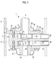
- FIG. 1 A longitudinal sectional view of a rotary compressor related to the first embodiment of the invention is illustrated in Fig. 1 .
- a rotary compressor 1 of the present embodiment can be applied to a single-stage multi-cylinder rotary compressor or a multi-stage rotary compressor, and a two-cylinder type hermetic rotary compressor provided with two cylinders is illustrated herein.
- the rotary compressor 1 is provided with a sealed housing 2, and has a configuration in which a rotary compression mechanism 7 driven via a rotating shaft (crankshaft) 3 by a motor (not illustrated) provided at an upper part within the sealed housing 2 is provided in a lower part in the sealed housing 2.
- the rotating shaft (crankshaft) 3 has an upper part inked with a rotor of the electric motor and is rotationally driven by the electric motor, and has first and second eccentric shaft parts (crank part) 4 and 5 provided at a lower part thereof so as to shift from each other with a phase of about 180 degrees in two upper and lower places at a predetermined interval.
- the rotating shaft 3 is divided by a center shaft part 6 between the first and second eccentric shaft parts 4 and 5 into two upper and lower pieces, and is configured such that the eccentric shaft parts are capable of being integrally linked with each other by screw linking or concavo-convex linking.
- the linking of the rotating shaft 3 divided into two pieces may be performed by means other than the screw linking or the concavo-convex linking.
- the rotary compression mechanism 7 is provided with an integrated-structure cylinder 11 having a configuration in which a first cylinder 8 is formed in an upper end surface, a second cylinder 9 is formed in a lower end surface, and a separator plate 10 partitioning the first cylinder 8 and the second cylinder 9 is integrally formed in the center.
- the separator plate 10 is provided with a through-hole 12 having a diameter such that at least the center shaft part 6 of the rotating shaft 3 is capable of passing through the through-hole.
- the upper bearing member 13 and the lower bearing member 14 rotatably support lower regions of the rotating shaft 3 in two upper and lower places with the integrated-structure cylinder 11 interposed therebetween.
- Covers 18 and 19 are respectively and integrally tightened to and formed in outer surfaces of the upper bearing member 13 and the lower bearing member 14 via the plurality of bolts 15, and discharge chambers 20 and 21 that discharge compressed gas are formed in the outer surfaces.
- the upper bearing member 13 has a configuration in which the rotary compression mechanism 7 is fixed to and installed within the sealed housing 2 by being plug-welded or crimped to an inner peripheral surface of the sealed housing 2 in a plurality of places (for example, three places).
- the integrated-structure cylinder 11 is fixed to and installed in the upper bearing member 13, and the lower bearing member 14 is fixed to and installed in the integrated-structure cylinder 11.
- the first and second eccentric shaft parts 4 and 5 provided at the rotating shaft 3 are respectively provided to correspond to the inside of the first cylinder chamber 16 and the inside of the second cylinder chamber 17.
- Rotors (pistons) 22 and 23 are respectively and rotatably fitted to outer peripheries of the first and second eccentric shaft parts 4 and 5.
- Rotors 22 and 23 are rotated along inner peripheral surfaces of the first cylinder chamber 16 and the second cylinder chamber 17 by the eccentric rotation of the first and second eccentric shaft parts 4 and 5.
- blade grooves are respectively provided to correspond to the first cylinder chamber 16 and the second cylinder chamber 17, as being publicly known, in the integrated-structure cylinder 11. Blades (not illustrated) that slide in the blade grooves are assembled into the blade grooves in a state where the blades are pressed against and biased to outer peripheries of the rotors 22 and 23.
- the inside of the first cylinder chamber 16 and the inside of the second cylinder chamber 17 are configured so as to be partitioned into a discharge side and an intake side by the blades.
- a plurality of intake ports 24 and 25 and a plurality of intake pipe connection holes 26 and 27 that extend radially outward from the cylinder chambers 16 and 17 are respectively provided to correspond to the first cylinder chamber 16 and the second cylinder chamber 17 in the integrated-structure cylinder 11.
- Intake pipes 28 and 29 from an accumulator or the like are configured so as to be connectable to the intake pipe connection holes 26 and 27. Accordingly, low-pressure refrigerant gas is taken into the first cylinder chamber 16 and the second cylinder chamber 17 via the intake ports 24 and 25 from the intake pipes 28 and 29.
- a peripheral region in which at least the intake ports 24 and 25 and the intake pipe connection holes 26 and 27 are provided is configured such that a cylinder wall from one end of the integrated-structure cylinder 11 to the other end thereof is a continuous wall and intake ports 24 and 25 and intake pipe connection holes 26 and 27 with larger diameter are capable of being drilled therein within the cylinder width (thickness) without being restricted by the width (thickness) of the first cylinder chamber 16 and the second cylinder chamber 17.
- the integrated-structure cylinder 11 may be adapted so as to provide cutout parts or thickness-reducing parts in other parts than the intake ports 24 and 25 and the intake pipe connection holes 26 and 27 and further the parts in which the above blade grooves are provided and to reduce material cost or weight.
- the low-pressure refrigerant gas taken into the first cylinder chamber 16 and the second cylinder chamber 17 through the intake ports 24 and 25 from the intake pipes 28 and 29 is compressed when the rotating shaft 3 is rotationally driven, and the rotors 22 and 23 are eccentrically rotated along the inner peripheral surfaces of the first cylinder chamber 16 and the second cylinder chamber 17 along with this.
- the gas compressed to a set pressure is discharged into the discharge chambers 20 and 21 via discharge valves and discharge ports, which are not illustrated, is discharged into the sealed housing 2 from the discharge chambers, and is then delivered to the outside of the compressor 1.
- the rotating shaft 3 provided with the plurality of eccentric shaft parts 4 and 5 at predetermined intervals in the axial direction is divided by the center shaft part 6 between the eccentric shaft parts 4 and 5 into upper and lower pieces and into a rotating shaft 3 having a divided structure that can be integrally linked.
- the plurality of first cylinder 8 and second cylinder 9 have the first cylinder chamber 16 and the second cylinder chamber 17 formed in both end surfaces, and are configured as the integrated-structure cylinder 11 in which the separator plate 10 partitioning the cylinder chambers 16 and 17 is integrally formed in the center.
- the eccentric shaft parts 4 and 5 can be easily assembled without being passed through the through-hole 12 of the separator plate 10 by passing the center shaft part 6 of the rotating shaft 3 having the divided structure through the through-hole 12 of the separator plate 10, and then integrally linking the center shaft part with the through-hole.
- the width (thickness) of the respective cylinders 8 and 9 can be increased by the thickness of the separator plate 10, and the intake ports 24 and 25 and the intake pipe connection holes 26 and 27 can be provided within the increased cylinder width (thickness). Therefore, it is possible to set the diameter of the intake ports 24 and 25 or the pipe diameter of the intake pipes 28 and 29 without being restricted by the cylinder width.
- the present embodiment has a configuration in which the plurality of first cylinder chamber 16 and second cylinder chamber 17 of which both ends are closed by installing the upper bearing member 13 and the lower bearing member 14 are formed in both the end surfaces of the integrated-structure cylinder 11, and the rotating shaft 3 is rotatably supported by the upper bearing member 13 and the lower bearing member 14 on both the end surfaces.
- the plurality of first cylinder chamber 16 and second cylinder chamber 17 of which both ends are closed by the integrally formed separator plate 10 can be formed by installing the upper bearing member 13 and the lower bearing member 14 in both the end surfaces of the integrated-structure cylinder 11, and the rotating shaft 3 can be rotatably supported by the pair of upper bearing member 13 and lower bearing member 4.
- the intake ports 24 and 25 and the intake pipe connection holes 26 and 27 that extend radially outward from the cylinder chambers 16 and 17 are provided in the integrated-structure cylinder 11, and at least a portion from one end of a peripheral region around the intake ports and the intake pipe connection holes to the other end thereof is configured as a continuous wall.
- intake ports 24 and 25 and intake pipe connection holes 26 and 27 with larger diameter can be provided without being restricted by the width (thickness) of the first cylinder 8 and the second cylinder 9.
- the plurality of intake ports 24 and 25 and the plurality of intake pipe connection holes 26 and 27 are provided to correspond to the plurality of cylinder chambers 16 and 17. For this reason, even in a configuration in which the plurality of intake ports 24 and 25 and intake pipe connection holes 26 and 27 are provided to correspond to the plurality of cylinder chambers 16 and 17, the integrated-structure cylinder 11 is adopted. Accordingly, intake ports 24 and 25 and intake pipe connection holes 26 and 27 with larger diameter can be provided without being restricted by the respective cylinder width (thickness).
- the present embodiment is different from the above-described first embodiment in the configuration of an intake port 30 and an intake pipe connection hole 31. Since the other points are the same as those of the first embodiment, the description thereof will be omitted.
- one thick intake pipe 32 is made connectable by providing one large common intake port 30 that branches so as to straddle the separator plate 10 and communicate with the plurality of cylinder chambers 16 and 17 and by providing one large common intake pipe connection hole 31 communicating with the intake port 30.
- the intake port 30 into the one common intake port 30 that branches so as to straddle the separator plate 10 and communicates with the plurality of cylinder chambers 16 and 17 and by providing the one common intake pipe connection hole 31 communicating with the intake port 30, the one larger common intake port 30 and the one intake pipe connection hole 31 communicating with this common intake port can be provided in the integrated-structure cylinder 11 corresponding to the width of the plurality of cylinders, and refrigerant gas can be made to be taken into the plurality of cylinder chambers 16 and 17 via the larger intake port 30 having the branch configuration.
- the present embodiment is different from the above-described first embodiment in the configuration of an intake port 33 and an intake pipe connection hole 34. Since the other points are the same as those of the first embodiment, the description thereof will be omitted.
- one thick intake pipe 35 is made connectable by providing one large common intake port 33 communicating with the plurality of cylinder chambers 16 and 17 so as to straddle the separator plate 10 and providing one large common intake pipe connection hole 34 communicating with the intake port 33.
- the intake port 33 into the one common intake port 33 communicating with the plurality of cylinder chambers 16 and 17 so as to straddle the separator plate 10 and by providing the one common intake pipe connection hole 34 communicating with the intake port 33, the one larger common intake port 33 and the one intake pipe connection hole 34 communicating with this common intake port can be provided in the integrated-structure cylinder 11 corresponding to the width of the plurality of cylinders, and refrigerant gas can be made to be taken into the plurality of cylinder chambers 16 and 17 via the single larger intake port 33.
- the invention is not limited to the inventions related to the above embodiments, and appropriate changes can be made without departing from the scope of the invention.
- the integrated-structure cylinder 11 is installed in the resulting sealed housing with the bolts 15, and the lower bearing member 14 is installed in the integrated-structure cylinder 11 with the bolts 15 has been described in the above embodiment.
- the invention is not limited to this.
- a configuration may be adopted in which the integrated-structure cylinder 11 is fixed to and installed in the sealed housing 2, and the upper bearing member 13 and the lower bearing member 14 are fixed and installed with the bolts 15.
- the single-stage multi-cylinder rotary compressor 1 has been described. However, it is natural that the rotary compressor 1 may be applied to a multi-stage rotary compressor in which one cylinder of the first cylinder 8 and the second cylinder 9 is a low-stage compressing cylinder, and the other cylinder is a high-stage compressing cylinder.
Landscapes
- Engineering & Computer Science (AREA)
- Mechanical Engineering (AREA)
- General Engineering & Computer Science (AREA)
- Applications Or Details Of Rotary Compressors (AREA)
Abstract
Description
- The present invention relates to a multi-cylinder rotary compressor provided with a plurality of cylinders.
- In single-stage multi-cylinder rotary compressors or multi-stage rotary compressors, a plurality of cylinder chambers are constituted by providing a plurality of cylinders in the direction of a rotating shaft, sandwiching a separator plate between the cylinders, closing one end of each cylinder using the separator plate, and closing the other end using each bearing member. A rotor (piston) that rotates along an inner peripheral surface of each cylinder chamber is rotatably provided in an eccentric shaft part of the rotating shaft (crankshaft), and a compression operation is performed by the eccentric rotation of the rotor.
- In such rotary compressors, during assembling, it is necessary to pass the eccentric shaft part of the rotating shaft through a through-hole of the separator plate. Therefore, the diameter of the hole is increased, and assembling is made easy. However, this makes it impossible to ensure the sealing performance of the cylinder chambers. Therefore, as illustrated in Patent Document 1, there is provided a rotary compressor in which a rotating shaft is made dividable by a center shaft part between eccentric shaft parts, and the divided rotating shafts are integrally linked with each other after a separator plate is inserted into the center shaft part.
- [PTL 1] Japanese Unexamined Patent Application Publication No.
2010-121481 - The points for increasing the efficiency of the multi-cylinder rotary compressors are as follows. (1) To reduce leakage loss by making the cylinder width (thickness) small, and shortening the axial seal length between the outer peripheral surface of the rotor and the inner peripheral surface of the cylinder, and (2) To make the diameter of a journal part, the diameter of an eccentric shaft part, and the external diameter of the rotor small, respectively, and reduce the sliding loss during the rotation of the rotor. However, in the structures of the rotary compressors in the present situation, there were the following restrictions, and it was difficult to make a design that satisfies all of these points.
-
- A. Restrictions on intake pipe diameter: if the cylinder width (thickness) is made small, the pipe diameter of an intake pipe connected to the cylinder is restricted along with this, it is impossible to ensure a required pipe diameter, and efficiency is lowered due to an increase in intake pressure loss.
- B. Seal limits on separator plate: the diameter of the through-hole of the separator plate becomes a restriction on ensuring sealing performance, and consequently, the diameter cannot be made large unnecessarily, which becomes a restriction on assembling.
- C. Assembly limits on rotating shaft: although the eccentric shaft part of the rotating shaft should be passed through the diameter of the through-hole of the separator plate, the diameter of the through-hole cannot be increased. This hinders assembly performance, and becomes a hindrance on increasing the eccentricity of the eccentric shaft part.
- Although the seal limits on the separator plate and the assembly limits on the rotating shaft can be relaxed by configuring the rotating shaft so as to be dividable between the eccentric shaft parts as in Patent Document 1, the restrictions on intake pipe diameter cannot be eliminated. Additionally, even if the rotating shaft has the divided structure, it is necessary to assemble a compression mechanism by individually incorporating a plurality of cylinders and separator plates, a pair of bearing members provided at both ends of the cylinders, and the like, and install these within a housing, and improvements in the reduction of the number of components, simplified assembly, and the like could not be expected.
- The invention has been made in view of such circumstances, and an object thereof is to provide a rotary compressor that removes restrictions on intake pipe diameter, seal limits on a separator plate, assembly limits on a rotating shaft, and the like, makes possible a design with limitations exceeding that of the present situation, and achieves increased efficiency, a reduced number of components, and simplified assembly.
- In order to solve the above problems, the rotary compressor of the invention adopts the following means. That is, the multi-cylinder rotary compressor related to the invention is a multi-cylinder rotary compressor including a plurality of cylinders. A rotating shaft provided with a plurality of eccentric shaft parts at predetermined intervals in an axial direction is divided by a center shaft part between the eccentric shaft parts into a rotating shaft having a divided structure that can be integrally linked. The plurality of cylinders have cylinder chambers formed in both end surfaces, resulting in an integrated-structure cylinder in which a separator plate partitioning the cylinder chambers is integrally formed in the center.
- According to this configuration, even if a through-hole provided in the separator plate has a hole diameter that gives priority to ensuring of sealing performance, the eccentric shaft parts can be easily assembled without being passed through the through-hole of the separator plate by passing the center shaft part of the rotating shaft having the divided structure through the through-hole of the separator plate, and then integrally linking the center shaft part with the through-hole. Additionally, even if leakage loss is reduced by making the width (thickness) small, the width (thickness) of the integrated-structure cylinder can be increased by the thickness of the separator plate, and an intake port and an intake pipe connection hole can be provided within the increased cylinder width (thickness). Therefore, it is possible to set the diameter of the intake port or the pipe diameter of an intake pipe without being restricted by the cylinder width. Therefore, a design in which restrictions on the intake pipe diameter of the intake pipe, seal limits on the separator plate, assembly limits on the rotating shaft, and the like are removed is made possible, and increased efficiency of the multi-cylinder rotary compressor, a reduced number of components, and simplified assembly can be achieved.
- In the above rotary compressor, the plurality of cylinder chambers of which both ends are closed may be formed by bearing members being installed in both end surfaces of the integrated-structure cylinder, and the rotating shaft may be rotatably supported via the bearing members in both the end surfaces.
- According to this configuration, the plurality of cylinder chambers of which both ends are closed by the integrally formed separator plate can be formed by installing the bearing members, respectively, in both the end surfaces of the integrated-structure cylinder, and the rotating shaft can be rotatably supported via the pair of bearing members. Therefore, compared to a multi-cylinder rotary compressor of a related-art type in which a separator plate that is a separate component is sandwiched and assembled between a plurality of cylinders having separate configurations, and bearing members are incorporated into both ends of the separator plate, the number of components can be reduced, and simplification of the configuration and assembly of the components, downsizing, and the like can be achieved.
- In any rotary compressor of the above-described rotary compressors, an intake port and an intake pipe connection hole that extend radially outward from each of the cylinder chambers may be provided in the integrated-structure cylinder, and at least a portion from one end of a peripheral region around the intake port and the intake pipe connection hole to the other end thereof may be a continuous wall.
- According to this configuration, by forming the cylinder wall from one end of the peripheral region around the intake port and the intake pipe connection hole that extend in the radial direction from each of the cylinder chambers to the other end thereof as the continuous wall, an intake port and an intake pipe connection hole with larger diameter can be provided without being restricted by the width of the individual cylinder. Therefore, even if the cylinder width is made small, the diameter of the intake port or the pipe diameter of the intake pipe is not restricted, a problem such that intake efficiency is lowered due to an increase in pressure loss can be solved, and increased efficiency can be achieved.
- In the above rotary compressor, a plurality of intake ports and intake pipe connection holes may be provided to correspond to the plurality of cylinder chambers.
- According to this configuration, even if a plurality of intake ports and intake pipe connection holes are provided to correspond to the plurality of cylinder chambers, the integrated-structure cylinder is adopted. Accordingly, intake ports and intake pipe connection holes with larger diameter can be provided without being restricted by the width of the individual cylinders. Therefore, even if the cylinder width is made small, the diameter of the intake ports or the pipe diameter of the intake pipes is not restricted, a problem such that intake efficiency is lowered due to an increase in pressure loss can be solved, and increased efficiency can be achieved.
- In the above rotary compressor, the intake port may be one intake port that branches so as to straddle the separator plate and communicate with the plurality of cylinder chambers, and one intake pipe connection hole may be provided to communicate with the intake port.
- According to this configuration, the one larger common intake port and the one intake pipe connection hole communicating with this common intake port can be provided in the integrated-structure cylinder corresponding to the width of the plurality of cylinders. Accordingly, refrigerant gas can be made to be taken into the plurality of cylinder chambers via the intake port having the branch configuration. Therefore, even if the cylinder width is made small, the diameter of the intake port or the pipe diameter of the intake pipe is not restricted, a problem such that intake efficiency is lowered due to an increase in pressure loss can be solved, increased efficiency can be achieved, and the simplification of configuration and cost reduction can be achieved by making an intake pipe system a single system.
- In the above rotary compressor, the intake port may be one intake port that communicates with the plurality of cylinder chambers so as to straddle the separator plate, and one intake pipe connection hole may be provided in communication with the intake port.
- According to this configuration, the one larger common intake port and the one intake pipe connection hole communicating with this common intake port can be provided in the integrated-structure cylinder corresponding to the width of the plurality of cylinders. Accordingly, refrigerant gas can be made to be taken into the plurality of cylinder chambers via the intake port having a size so as to straddle the separator plate. Therefore, even if the cylinder width is made small, the diameter of the intake port or the pipe diameter of the intake pipe is not restricted, a problem such that intake efficiency is lowered due to an increase in pressure loss can be solved, increased efficiency can be achieved, and the simplification of configuration and cost reduction can be achieved by making an intake pipe system a single system. Advantageous Effects of Invention
- According to this invention, even if the through-hole provided in the separator plate has a hole diameter that gives priority to ensuring of sealing performance, the eccentric shaft parts can be easily assembled without being passed through the through-hole of the separator plate by passing the center shaft part of the rotating shaft having the divided structure through the through-hole of the separator plate, and then integrally linking the center shaft part with the through-hole. Additionally, even if leakage loss is reduced by making the cylinder width (thickness) small, the width (thickness) of the integrated-structure cylinder can be increased by the thickness of the separator plate, and the intake port and the intake pipe connection hole can be provided within the increased cylinder width (thickness). Therefore, it is possible to set the diameter of the intake port or the pipe diameter of the intake pipe without being restricted by the cylinder width. Therefore, a design in which restrictions on the intake pipe diameter of the intake pipe, seal limits on the separator plate, assembly limits on the rotating shaft, and the like are removed is made possible, and increased efficiency of the multi-cylinder rotary compressor, a reduced number of components, and simplified assembly can be achieved.
-
-
Fig. 1 is a longitudinal sectional view of a rotary compressor related to a first embodiment of the invention. -
Fig. 2 is a longitudinal sectional view of a rotary compressor related to a second embodiment of the invention. -
Fig. 3 is a longitudinal sectional view of a rotary compressor related to a third embodiment of the invention. - Hereinafter, embodiments related to the invention will be described with reference to the drawings.
- Hereinafter, a first embodiment of the invention will be described with reference to
Fig. 1 . - A longitudinal sectional view of a rotary compressor related to the first embodiment of the invention is illustrated in
Fig. 1 . - A rotary compressor 1 of the present embodiment can be applied to a single-stage multi-cylinder rotary compressor or a multi-stage rotary compressor, and a two-cylinder type hermetic rotary compressor provided with two cylinders is illustrated herein. The rotary compressor 1 is provided with a sealed
housing 2, and has a configuration in which arotary compression mechanism 7 driven via a rotating shaft (crankshaft) 3 by a motor (not illustrated) provided at an upper part within the sealedhousing 2 is provided in a lower part in the sealedhousing 2. - The rotating shaft (crankshaft) 3 has an upper part inked with a rotor of the electric motor and is rotationally driven by the electric motor, and has first and second eccentric shaft parts (crank part) 4 and 5 provided at a lower part thereof so as to shift from each other with a phase of about 180 degrees in two upper and lower places at a predetermined interval. The
rotating shaft 3 is divided by acenter shaft part 6 between the first and secondeccentric shaft parts rotating shaft 3 divided into two pieces may be performed by means other than the screw linking or the concavo-convex linking. - The
rotary compression mechanism 7 is provided with an integrated-structure cylinder 11 having a configuration in which afirst cylinder 8 is formed in an upper end surface, asecond cylinder 9 is formed in a lower end surface, and aseparator plate 10 partitioning thefirst cylinder 8 and thesecond cylinder 9 is integrally formed in the center. Theseparator plate 10 is provided with a through-hole 12 having a diameter such that at least thecenter shaft part 6 of therotating shaft 3 is capable of passing through the through-hole. - When an
upper bearing member 13 and alower bearing member 14 are respectively fixed to and installed in an upper end surface and a lower end surface of the integrated-structure cylinder 11 via a plurality ofbolts 15, an upper surface and a lower surface of thefirst cylinder 8 and thesecond cylinder 9 are sealed, respectively. This allows thefirst cylinder chamber 16 and thesecond cylinder chamber 17 serving as closed spaces to be configured. - The
upper bearing member 13 and thelower bearing member 14 rotatably support lower regions of therotating shaft 3 in two upper and lower places with the integrated-structure cylinder 11 interposed therebetween.Covers upper bearing member 13 and thelower bearing member 14 via the plurality ofbolts 15, anddischarge chambers - Additionally, the
upper bearing member 13 has a configuration in which therotary compression mechanism 7 is fixed to and installed within the sealedhousing 2 by being plug-welded or crimped to an inner peripheral surface of the sealedhousing 2 in a plurality of places (for example, three places). In addition, the integrated-structure cylinder 11 is fixed to and installed in theupper bearing member 13, and thelower bearing member 14 is fixed to and installed in the integrated-structure cylinder 11. - The first and second
eccentric shaft parts rotating shaft 3 are respectively provided to correspond to the inside of thefirst cylinder chamber 16 and the inside of thesecond cylinder chamber 17. Rotors (pistons) 22 and 23 are respectively and rotatably fitted to outer peripheries of the first and secondeccentric shaft parts Rotors first cylinder chamber 16 and thesecond cylinder chamber 17 by the eccentric rotation of the first and secondeccentric shaft parts - Additionally, blade grooves (not illustrated) are respectively provided to correspond to the
first cylinder chamber 16 and thesecond cylinder chamber 17, as being publicly known, in the integrated-structure cylinder 11. Blades (not illustrated) that slide in the blade grooves are assembled into the blade grooves in a state where the blades are pressed against and biased to outer peripheries of therotors first cylinder chamber 16 and the inside of thesecond cylinder chamber 17 are configured so as to be partitioned into a discharge side and an intake side by the blades. - Moreover, a plurality of
intake ports cylinder chambers first cylinder chamber 16 and thesecond cylinder chamber 17 in the integrated-structure cylinder 11.Intake pipes first cylinder chamber 16 and thesecond cylinder chamber 17 via theintake ports intake pipes - In the integrated-
structure cylinder 11, a peripheral region in which at least theintake ports structure cylinder 11 to the other end thereof is a continuous wall andintake ports first cylinder chamber 16 and thesecond cylinder chamber 17. In addition, the integrated-structure cylinder 11 may be adapted so as to provide cutout parts or thickness-reducing parts in other parts than theintake ports - By virtue of the configuration described above, according to the present embodiment, the following working effects are exhibited.
- In the above rotary compressor 1, the low-pressure refrigerant gas taken into the
first cylinder chamber 16 and thesecond cylinder chamber 17 through theintake ports intake pipes rotating shaft 3 is rotationally driven, and therotors first cylinder chamber 16 and thesecond cylinder chamber 17 along with this. Then, the gas compressed to a set pressure is discharged into thedischarge chambers housing 2 from the discharge chambers, and is then delivered to the outside of the compressor 1. - In this multi-cylinder rotary compressor, leakage loss can be reduced by making the cylinder width (thickness) small as mentioned above. However there were the following problems. That is, if the cylinder width is made small, the intake pipe diameter is restricted, and efficiency is lowered due to an increase in intake pressure loss. Additionally, although it is desired to increase the diameter of the through-hole of the separator plate to allow the eccentric shaft part of the rotating shaft to easily pass therethrough, if the diameter of the through-hole is increased, ensuring of sealing performance becomes difficult and lowering in efficiency is caused. Moreover, the assembly performance of the rotating shaft having the eccentric shaft part is limited by the diameter of the through-hole of the separator plate, and eccentricity of the eccentric shaft part cannot be increased.
- However, in the present embodiment, the
rotating shaft 3 provided with the plurality ofeccentric shaft parts center shaft part 6 between theeccentric shaft parts rotating shaft 3 having a divided structure that can be integrally linked. The plurality offirst cylinder 8 andsecond cylinder 9 have thefirst cylinder chamber 16 and thesecond cylinder chamber 17 formed in both end surfaces, and are configured as the integrated-structure cylinder 11 in which theseparator plate 10 partitioning thecylinder chambers - For this reason, even if the through-
hole 12 provided in theseparator plate 10 has a hole diameter that gives priority to ensuring of sealing performance, theeccentric shaft parts hole 12 of theseparator plate 10 by passing thecenter shaft part 6 of therotating shaft 3 having the divided structure through the through-hole 12 of theseparator plate 10, and then integrally linking the center shaft part with the through-hole. Additionally, even if leakage loss is reduced by making the width (thickness) of therespective cylinders structure cylinder 11 can be increased by the thickness of theseparator plate 10, and theintake ports intake ports intake pipes - Accordingly, it is possible to remove limitations or restrictions, such as restrictions on the intake pipe diameter of the
intake pipes separator plate 10, and assembly limits on therotating shaft 3, a design exceeding that in the present situation is made possible, and increased efficiency of the multi-cylinder rotary compressor 1, a reduced number of components, and simplified assembly can be achieved. - Additionally, the present embodiment has a configuration in which the plurality of
first cylinder chamber 16 andsecond cylinder chamber 17 of which both ends are closed by installing theupper bearing member 13 and thelower bearing member 14 are formed in both the end surfaces of the integrated-structure cylinder 11, and therotating shaft 3 is rotatably supported by theupper bearing member 13 and thelower bearing member 14 on both the end surfaces. For this reason, the plurality offirst cylinder chamber 16 andsecond cylinder chamber 17 of which both ends are closed by the integrally formedseparator plate 10 can be formed by installing theupper bearing member 13 and thelower bearing member 14 in both the end surfaces of the integrated-structure cylinder 11, and therotating shaft 3 can be rotatably supported by the pair of upper bearingmember 13 andlower bearing member 4. - Therefore, compared to a multi-cylinder rotary compressor of a related-art type in which a separator plate that is a separate component is sandwiched and assembled between a plurality of cylinders that are separately configured, and bearing members are incorporated into both ends of the separator plate, the number of components can be markedly reduced, and simplification of the configuration and assembly of the components, downsizing, and the like can be achieved.
- Moreover, the
intake ports cylinder chambers structure cylinder 11, and at least a portion from one end of a peripheral region around the intake ports and the intake pipe connection holes to the other end thereof is configured as a continuous wall. In this way, by forming the cylinder wall from one end of the peripheral region around theintake ports cylinder chambers intake ports first cylinder 8 and thesecond cylinder 9. - For this reason, even if leakage loss is reduced by making the cylinder width of the
first cylinder 8 and thesecond cylinder 9 small, the diameter of theintake ports intake pipes - Additionally, in the present embodiment, the plurality of
intake ports cylinder chambers intake ports cylinder chambers structure cylinder 11 is adopted. Accordingly,intake ports intake ports intake pipes - Next, a second embodiment of the invention will be described with reference to
Fig. 2 . - The present embodiment is different from the above-described first embodiment in the configuration of an
intake port 30 and an intakepipe connection hole 31. Since the other points are the same as those of the first embodiment, the description thereof will be omitted. - In the present embodiment, as illustrated in
Fig. 2 , onethick intake pipe 32 is made connectable by providing one largecommon intake port 30 that branches so as to straddle theseparator plate 10 and communicate with the plurality ofcylinder chambers pipe connection hole 31 communicating with theintake port 30. - In this way, by forming the
intake port 30 into the onecommon intake port 30 that branches so as to straddle theseparator plate 10 and communicates with the plurality ofcylinder chambers pipe connection hole 31 communicating with theintake port 30, the one largercommon intake port 30 and the one intakepipe connection hole 31 communicating with this common intake port can be provided in the integrated-structure cylinder 11 corresponding to the width of the plurality of cylinders, and refrigerant gas can be made to be taken into the plurality ofcylinder chambers larger intake port 30 having the branch configuration. - For this reason, even if the cylinder width (thickness) is made small, the diameter of the
intake port 30 or the pipe diameter of theintake pipe 32 is not restricted by this, a problem such that intake efficiency is lowered due an increase in pressure loss can be solved, further increased efficiency can be achieved, and the simplification of configuration and cost reduction can be achieved by making an intake pipe system a single system. - Next, a third embodiment of the invention will be described with reference to
Fig. 3 . - The present embodiment is different from the above-described first embodiment in the configuration of an
intake port 33 and an intakepipe connection hole 34. Since the other points are the same as those of the first embodiment, the description thereof will be omitted. - In the present embodiment, as illustrated in
Fig. 3 , onethick intake pipe 35 is made connectable by providing one largecommon intake port 33 communicating with the plurality ofcylinder chambers separator plate 10 and providing one large common intakepipe connection hole 34 communicating with theintake port 33. - In this way, by forming the
intake port 33 into the onecommon intake port 33 communicating with the plurality ofcylinder chambers separator plate 10 and by providing the one common intakepipe connection hole 34 communicating with theintake port 33, the one largercommon intake port 33 and the one intakepipe connection hole 34 communicating with this common intake port can be provided in the integrated-structure cylinder 11 corresponding to the width of the plurality of cylinders, and refrigerant gas can be made to be taken into the plurality ofcylinder chambers larger intake port 33. - For this reason, even if the cylinder width (thickness) is made small, the diameter of the
intake port 33 or the pipe diameter of theintake pipe 35 is not restricted by this, a problem such that intake efficiency is lowered due an increase in pressure loss can be solved, further increased efficiency can be achieved, and the simplification of configuration and cost reduction can be achieved by making an intake pipe system a single system. - In addition, the invention is not limited to the inventions related to the above embodiments, and appropriate changes can be made without departing from the scope of the invention. For example, an example in which the
upper bearing member 13 is fixed to and installed in the sealedhousing 2 by welding, crimping, or the like, the integrated-structure cylinder 11 is installed in the resulting sealed housing with thebolts 15, and thelower bearing member 14 is installed in the integrated-structure cylinder 11 with thebolts 15 has been described in the above embodiment. However, the invention is not limited to this. A configuration may be adopted in which the integrated-structure cylinder 11 is fixed to and installed in the sealedhousing 2, and theupper bearing member 13 and thelower bearing member 14 are fixed and installed with thebolts 15. - Additionally, in the above embodiment, the single-stage multi-cylinder rotary compressor 1 has been described. However, it is natural that the rotary compressor 1 may be applied to a multi-stage rotary compressor in which one cylinder of the
first cylinder 8 and thesecond cylinder 9 is a low-stage compressing cylinder, and the other cylinder is a high-stage compressing cylinder. -
- 1:
- ROTARY COMPRESSOR
- 3:
- ROTATING SHAFT
- 4:
- FIRST ECCENTRIC SHAFT PART
- 5:
- SECOND ECCENTRIC SHAFT PART
- 6:
- CENTER SHAFT PART
- 8:
- FIRST CYLINDER
- 9:
- SECOND CYLINDER
- 10:
- SEPARATOR PLATE
- 11:
- INTEGRATED-STRUCTURE CYLINDER
- 13:
- UPPER BEARING MEMBER
- 14:
- LOWER BEARING MEMBER
- 16:
- FIRST CYLINDER CHAMBER
- 17:
- SECOND CYLINDER CHAMBER
- 23, 24, 30, 33:
- INTAKE PORT
- 25, 26, 31, 34:
- INTAKE PIPE CONNECTION HOLE
Claims (6)
- A multi-cylinder rotary compressor comprising a plurality of cylinders,
wherein a rotating shaft provided with a plurality of eccentric shaft parts at predetermined intervals in an axial direction is divided by a center shaft part between the eccentric shaft parts into a rotating shaft having a divided structure that can be integrally linked, and
wherein the plurality of cylinders have cylinder chambers formed in both end surfaces, resulting in an integrated-structure cylinder in which a separator plate partitioning the cylinder chambers is integrally formed in the center. - The rotary compressor according to Claim 1,
wherein the plurality of cylinder chambers of which both ends are closed are formed by bearing members being installed in both end surfaces of the integrated-structure cylinder, and the rotating shaft is rotatably supported via the bearing members in both the end surfaces. - The rotary compressor according to Claim 1 or 2, wherein an intake port and an intake pipe connection hole that extend radially outward from each of the cylinder chambers are provided in the integrated-structure cylinder, and at least a portion from one end of a peripheral region around the intake port and the intake pipe connection hole to the other end thereof is a continuous wall.
- The rotary compressor according to Claim 3,
wherein a plurality of the intake ports and the intake pipe connection holes are provided to correspond to the plurality of cylinder chambers. - The rotary compressor according to Claim 3,
wherein the intake port is one intake port that branches so as to straddle the separator plate and communicate with the plurality of cylinder chambers, and one intake pipe connection hole is provided in communication with the intake port. - The rotary compressor according to Claim 3,
wherein the intake port is one intake port that communicates with the plurality of cylinder chambers so as to straddle the separator plate, and one intake pipe connection hole is provided to communicate with the intake port.
Applications Claiming Priority (2)
| Application Number | Priority Date | Filing Date | Title |
|---|---|---|---|
| JP2013201575A JP6045468B2 (en) | 2013-09-27 | 2013-09-27 | Rotary compressor |
| PCT/JP2014/071702 WO2015045678A1 (en) | 2013-09-27 | 2014-08-20 | Rotary compressor |
Publications (3)
| Publication Number | Publication Date |
|---|---|
| EP3015712A1 true EP3015712A1 (en) | 2016-05-04 |
| EP3015712A4 EP3015712A4 (en) | 2016-05-11 |
| EP3015712B1 EP3015712B1 (en) | 2019-05-01 |
Family
ID=52742832
Family Applications (1)
| Application Number | Title | Priority Date | Filing Date |
|---|---|---|---|
| EP14849841.3A Active EP3015712B1 (en) | 2013-09-27 | 2014-08-20 | Rotary compressor |
Country Status (4)
| Country | Link |
|---|---|
| EP (1) | EP3015712B1 (en) |
| JP (1) | JP6045468B2 (en) |
| CN (1) | CN105392995B (en) |
| WO (1) | WO2015045678A1 (en) |
Families Citing this family (9)
| Publication number | Priority date | Publication date | Assignee | Title |
|---|---|---|---|---|
| CN104791249A (en) * | 2015-04-15 | 2015-07-22 | 广东美芝制冷设备有限公司 | Compressor component and double-cylinder rotary compressor adopting same |
| CN105065278B (en) * | 2015-07-24 | 2017-08-25 | 郑州凌达压缩机有限公司 | Compressor and combination structure and assembly method of pump body and shell of compressor |
| JP6570930B2 (en) | 2015-09-09 | 2019-09-04 | 三菱重工サーマルシステムズ株式会社 | Rotary compressor and method for manufacturing the same |
| JP6574519B2 (en) * | 2016-03-25 | 2019-09-11 | 東芝キヤリア株式会社 | Hermetic rotary compressor and refrigeration cycle apparatus |
| CN106246551B (en) * | 2016-09-18 | 2018-04-13 | 珠海格力节能环保制冷技术研究中心有限公司 | Bent axle, pump assembly and compressor |
| CN106523363B (en) * | 2017-01-03 | 2019-01-08 | 珠海格力节能环保制冷技术研究中心有限公司 | A kind of compressor, compressor pump and temperature equipment |
| WO2018103476A1 (en) | 2016-12-05 | 2018-06-14 | 珠海格力节能环保制冷技术研究中心有限公司 | Air cylinder, pump body assembly, compressor, and temperature adjusting apparatus |
| CN110296081A (en) * | 2019-06-21 | 2019-10-01 | 珠海格力节能环保制冷技术研究中心有限公司 | The assembly method of pump assembly, compressor and pump assembly |
| CN117889083B (en) * | 2024-01-29 | 2025-11-21 | 广东美芝精密制造有限公司 | Pump assembly, compressor and refrigeration equipment |
Family Cites Families (9)
| Publication number | Priority date | Publication date | Assignee | Title |
|---|---|---|---|---|
| JPS63126580A (en) * | 1986-11-18 | 1988-05-30 | Isuzu Motors Ltd | Painting method for reactive injection molding of resin essentially consisting of polydicyclopentadiene |
| JPS63126580U (en) * | 1987-02-13 | 1988-08-18 | ||
| JPH03222887A (en) * | 1990-01-25 | 1991-10-01 | Mitsubishi Heavy Ind Ltd | Two-cylindered rotary compressor |
| CN1324240C (en) * | 1998-02-13 | 2007-07-04 | 松下电器产业株式会社 | Hermetic compressor |
| KR100432115B1 (en) * | 2000-10-30 | 2004-05-17 | 가부시키가이샤 히타치세이사쿠쇼 | Plural cylinder rotary compressor |
| WO2009028633A1 (en) * | 2007-08-28 | 2009-03-05 | Toshiba Carrier Corporation | Multicylinder rotary type compressor, and refrigerating cycle apparatus |
| JP2010121481A (en) * | 2008-11-18 | 2010-06-03 | Mitsubishi Electric Corp | Rotary compressor |
| JP5341031B2 (en) * | 2010-06-30 | 2013-11-13 | 三菱電機株式会社 | Multi-cylinder rotary compressor, its assembling method and its manufacturing apparatus |
| CN102748289A (en) * | 2011-04-19 | 2012-10-24 | 广东美芝制冷设备有限公司 | Double-cylinder rotary compressor |
-
2013
- 2013-09-27 JP JP2013201575A patent/JP6045468B2/en active Active
-
2014
- 2014-08-20 WO PCT/JP2014/071702 patent/WO2015045678A1/en not_active Ceased
- 2014-08-20 EP EP14849841.3A patent/EP3015712B1/en active Active
- 2014-08-20 CN CN201480040413.0A patent/CN105392995B/en active Active
Also Published As
| Publication number | Publication date |
|---|---|
| JP2015068211A (en) | 2015-04-13 |
| EP3015712B1 (en) | 2019-05-01 |
| CN105392995B (en) | 2018-04-27 |
| JP6045468B2 (en) | 2016-12-14 |
| CN105392995A (en) | 2016-03-09 |
| EP3015712A4 (en) | 2016-05-11 |
| WO2015045678A1 (en) | 2015-04-02 |
Similar Documents
| Publication | Publication Date | Title |
|---|---|---|
| EP3015712B1 (en) | Rotary compressor | |
| KR101673739B1 (en) | Electric compressor | |
| US20150064042A1 (en) | Gas compressor | |
| CN104302923A (en) | Gas compressor | |
| CZ305876B6 (en) | Rotary compressor | |
| US11022118B2 (en) | Concentric vane compressor | |
| EP3951181B1 (en) | Rotary compressor | |
| JP6127722B2 (en) | Rotary compressor | |
| JP5535511B2 (en) | Method for manufacturing hermetic fluid machine and hermetic fluid machine | |
| EP2549109B1 (en) | Scroll compressor | |
| CN103857913B (en) | Multi-cylinder rotary compressor | |
| EP3647595B1 (en) | Rotary compressor | |
| CN103362802A (en) | Scroll compressor having a plurality of scroll members | |
| EP3141754B1 (en) | Rotary compressor and method for manufacturing the same | |
| EP3141755B1 (en) | Rotary compressor | |
| CN109595166A (en) | Compressor | |
| EP2253849B1 (en) | Hermetic compressor | |
| KR101418288B1 (en) | Hermetic compressor | |
| WO2016110982A1 (en) | Multi-cylinder hermetic compressor | |
| KR200392423Y1 (en) | Structure of sealing for twin rotary compressor | |
| CZ306346B6 (en) | Compressor | |
| KR200382995Y1 (en) | Accmulator for twin rotary compressor | |
| EP3647596B1 (en) | Rotary compressor | |
| KR20060087259A (en) | Compressor Part Assembly Structure of Double Rotary Compressor | |
| JP2013174180A (en) | Scroll compressor |
Legal Events
| Date | Code | Title | Description |
|---|---|---|---|
| PUAI | Public reference made under article 153(3) epc to a published international application that has entered the european phase |
Free format text: ORIGINAL CODE: 0009012 |
|
| 17P | Request for examination filed |
Effective date: 20160125 |
|
| AK | Designated contracting states |
Kind code of ref document: A1 Designated state(s): AL AT BE BG CH CY CZ DE DK EE ES FI FR GB GR HR HU IE IS IT LI LT LU LV MC MK MT NL NO PL PT RO RS SE SI SK SM TR |
|
| AX | Request for extension of the european patent |
Extension state: BA ME |
|
| A4 | Supplementary search report drawn up and despatched |
Effective date: 20160408 |
|
| RIC1 | Information provided on ipc code assigned before grant |
Ipc: F04C 18/356 20060101ALI20160404BHEP Ipc: F04C 23/00 20060101AFI20160404BHEP Ipc: F04C 29/00 20060101ALI20160404BHEP |
|
| DAX | Request for extension of the european patent (deleted) | ||
| RAP1 | Party data changed (applicant data changed or rights of an application transferred) |
Owner name: MITSUBISHI HEAVY INDUSTRIES THERMAL SYSTEMS, LTD. |
|
| GRAP | Despatch of communication of intention to grant a patent |
Free format text: ORIGINAL CODE: EPIDOSNIGR1 |
|
| STAA | Information on the status of an ep patent application or granted ep patent |
Free format text: STATUS: GRANT OF PATENT IS INTENDED |
|
| RIC1 | Information provided on ipc code assigned before grant |
Ipc: F04C 18/356 20060101ALI20181210BHEP Ipc: F04C 23/00 20060101AFI20181210BHEP Ipc: F04C 29/00 20060101ALI20181210BHEP |
|
| INTG | Intention to grant announced |
Effective date: 20190108 |
|
| GRAS | Grant fee paid |
Free format text: ORIGINAL CODE: EPIDOSNIGR3 |
|
| GRAA | (expected) grant |
Free format text: ORIGINAL CODE: 0009210 |
|
| STAA | Information on the status of an ep patent application or granted ep patent |
Free format text: STATUS: THE PATENT HAS BEEN GRANTED |
|
| AK | Designated contracting states |
Kind code of ref document: B1 Designated state(s): AL AT BE BG CH CY CZ DE DK EE ES FI FR GB GR HR HU IE IS IT LI LT LU LV MC MK MT NL NO PL PT RO RS SE SI SK SM TR |
|
| REG | Reference to a national code |
Ref country code: GB Ref legal event code: FG4D |
|
| REG | Reference to a national code |
Ref country code: CH Ref legal event code: EP Ref country code: AT Ref legal event code: REF Ref document number: 1127295 Country of ref document: AT Kind code of ref document: T Effective date: 20190515 |
|
| REG | Reference to a national code |
Ref country code: DE Ref legal event code: R096 Ref document number: 602014045980 Country of ref document: DE |
|
| REG | Reference to a national code |
Ref country code: IE Ref legal event code: FG4D |
|
| REG | Reference to a national code |
Ref country code: NL Ref legal event code: MP Effective date: 20190501 |
|
| REG | Reference to a national code |
Ref country code: LT Ref legal event code: MG4D |
|
| PG25 | Lapsed in a contracting state [announced via postgrant information from national office to epo] |
Ref country code: FI Free format text: LAPSE BECAUSE OF FAILURE TO SUBMIT A TRANSLATION OF THE DESCRIPTION OR TO PAY THE FEE WITHIN THE PRESCRIBED TIME-LIMIT Effective date: 20190501 Ref country code: NO Free format text: LAPSE BECAUSE OF FAILURE TO SUBMIT A TRANSLATION OF THE DESCRIPTION OR TO PAY THE FEE WITHIN THE PRESCRIBED TIME-LIMIT Effective date: 20190801 Ref country code: HR Free format text: LAPSE BECAUSE OF FAILURE TO SUBMIT A TRANSLATION OF THE DESCRIPTION OR TO PAY THE FEE WITHIN THE PRESCRIBED TIME-LIMIT Effective date: 20190501 Ref country code: LT Free format text: LAPSE BECAUSE OF FAILURE TO SUBMIT A TRANSLATION OF THE DESCRIPTION OR TO PAY THE FEE WITHIN THE PRESCRIBED TIME-LIMIT Effective date: 20190501 Ref country code: ES Free format text: LAPSE BECAUSE OF FAILURE TO SUBMIT A TRANSLATION OF THE DESCRIPTION OR TO PAY THE FEE WITHIN THE PRESCRIBED TIME-LIMIT Effective date: 20190501 Ref country code: PT Free format text: LAPSE BECAUSE OF FAILURE TO SUBMIT A TRANSLATION OF THE DESCRIPTION OR TO PAY THE FEE WITHIN THE PRESCRIBED TIME-LIMIT Effective date: 20190901 Ref country code: SE Free format text: LAPSE BECAUSE OF FAILURE TO SUBMIT A TRANSLATION OF THE DESCRIPTION OR TO PAY THE FEE WITHIN THE PRESCRIBED TIME-LIMIT Effective date: 20190501 Ref country code: NL Free format text: LAPSE BECAUSE OF FAILURE TO SUBMIT A TRANSLATION OF THE DESCRIPTION OR TO PAY THE FEE WITHIN THE PRESCRIBED TIME-LIMIT Effective date: 20190501 Ref country code: AL Free format text: LAPSE BECAUSE OF FAILURE TO SUBMIT A TRANSLATION OF THE DESCRIPTION OR TO PAY THE FEE WITHIN THE PRESCRIBED TIME-LIMIT Effective date: 20190501 |
|
| PG25 | Lapsed in a contracting state [announced via postgrant information from national office to epo] |
Ref country code: BG Free format text: LAPSE BECAUSE OF FAILURE TO SUBMIT A TRANSLATION OF THE DESCRIPTION OR TO PAY THE FEE WITHIN THE PRESCRIBED TIME-LIMIT Effective date: 20190801 Ref country code: LV Free format text: LAPSE BECAUSE OF FAILURE TO SUBMIT A TRANSLATION OF THE DESCRIPTION OR TO PAY THE FEE WITHIN THE PRESCRIBED TIME-LIMIT Effective date: 20190501 Ref country code: RS Free format text: LAPSE BECAUSE OF FAILURE TO SUBMIT A TRANSLATION OF THE DESCRIPTION OR TO PAY THE FEE WITHIN THE PRESCRIBED TIME-LIMIT Effective date: 20190501 Ref country code: GR Free format text: LAPSE BECAUSE OF FAILURE TO SUBMIT A TRANSLATION OF THE DESCRIPTION OR TO PAY THE FEE WITHIN THE PRESCRIBED TIME-LIMIT Effective date: 20190802 |
|
| REG | Reference to a national code |
Ref country code: AT Ref legal event code: MK05 Ref document number: 1127295 Country of ref document: AT Kind code of ref document: T Effective date: 20190501 |
|
| PG25 | Lapsed in a contracting state [announced via postgrant information from national office to epo] |
Ref country code: IS Free format text: LAPSE BECAUSE OF FAILURE TO SUBMIT A TRANSLATION OF THE DESCRIPTION OR TO PAY THE FEE WITHIN THE PRESCRIBED TIME-LIMIT Effective date: 20190901 |
|
| PG25 | Lapsed in a contracting state [announced via postgrant information from national office to epo] |
Ref country code: SK Free format text: LAPSE BECAUSE OF FAILURE TO SUBMIT A TRANSLATION OF THE DESCRIPTION OR TO PAY THE FEE WITHIN THE PRESCRIBED TIME-LIMIT Effective date: 20190501 Ref country code: AT Free format text: LAPSE BECAUSE OF FAILURE TO SUBMIT A TRANSLATION OF THE DESCRIPTION OR TO PAY THE FEE WITHIN THE PRESCRIBED TIME-LIMIT Effective date: 20190501 Ref country code: DK Free format text: LAPSE BECAUSE OF FAILURE TO SUBMIT A TRANSLATION OF THE DESCRIPTION OR TO PAY THE FEE WITHIN THE PRESCRIBED TIME-LIMIT Effective date: 20190501 Ref country code: EE Free format text: LAPSE BECAUSE OF FAILURE TO SUBMIT A TRANSLATION OF THE DESCRIPTION OR TO PAY THE FEE WITHIN THE PRESCRIBED TIME-LIMIT Effective date: 20190501 Ref country code: CZ Free format text: LAPSE BECAUSE OF FAILURE TO SUBMIT A TRANSLATION OF THE DESCRIPTION OR TO PAY THE FEE WITHIN THE PRESCRIBED TIME-LIMIT Effective date: 20190501 Ref country code: RO Free format text: LAPSE BECAUSE OF FAILURE TO SUBMIT A TRANSLATION OF THE DESCRIPTION OR TO PAY THE FEE WITHIN THE PRESCRIBED TIME-LIMIT Effective date: 20190501 |
|
| REG | Reference to a national code |
Ref country code: DE Ref legal event code: R097 Ref document number: 602014045980 Country of ref document: DE |
|
| PG25 | Lapsed in a contracting state [announced via postgrant information from national office to epo] |
Ref country code: IT Free format text: LAPSE BECAUSE OF FAILURE TO SUBMIT A TRANSLATION OF THE DESCRIPTION OR TO PAY THE FEE WITHIN THE PRESCRIBED TIME-LIMIT Effective date: 20190501 Ref country code: SM Free format text: LAPSE BECAUSE OF FAILURE TO SUBMIT A TRANSLATION OF THE DESCRIPTION OR TO PAY THE FEE WITHIN THE PRESCRIBED TIME-LIMIT Effective date: 20190501 |
|
| PLBE | No opposition filed within time limit |
Free format text: ORIGINAL CODE: 0009261 |
|
| STAA | Information on the status of an ep patent application or granted ep patent |
Free format text: STATUS: NO OPPOSITION FILED WITHIN TIME LIMIT |
|
| PG25 | Lapsed in a contracting state [announced via postgrant information from national office to epo] |
Ref country code: TR Free format text: LAPSE BECAUSE OF FAILURE TO SUBMIT A TRANSLATION OF THE DESCRIPTION OR TO PAY THE FEE WITHIN THE PRESCRIBED TIME-LIMIT Effective date: 20190501 |
|
| 26N | No opposition filed |
Effective date: 20200204 |
|
| PG25 | Lapsed in a contracting state [announced via postgrant information from national office to epo] |
Ref country code: PL Free format text: LAPSE BECAUSE OF FAILURE TO SUBMIT A TRANSLATION OF THE DESCRIPTION OR TO PAY THE FEE WITHIN THE PRESCRIBED TIME-LIMIT Effective date: 20190501 |
|
| PG25 | Lapsed in a contracting state [announced via postgrant information from national office to epo] |
Ref country code: MC Free format text: LAPSE BECAUSE OF FAILURE TO SUBMIT A TRANSLATION OF THE DESCRIPTION OR TO PAY THE FEE WITHIN THE PRESCRIBED TIME-LIMIT Effective date: 20190501 Ref country code: SI Free format text: LAPSE BECAUSE OF FAILURE TO SUBMIT A TRANSLATION OF THE DESCRIPTION OR TO PAY THE FEE WITHIN THE PRESCRIBED TIME-LIMIT Effective date: 20190501 Ref country code: CH Free format text: LAPSE BECAUSE OF NON-PAYMENT OF DUE FEES Effective date: 20190831 Ref country code: LU Free format text: LAPSE BECAUSE OF NON-PAYMENT OF DUE FEES Effective date: 20190820 Ref country code: LI Free format text: LAPSE BECAUSE OF NON-PAYMENT OF DUE FEES Effective date: 20190831 |
|
| REG | Reference to a national code |
Ref country code: BE Ref legal event code: MM Effective date: 20190831 |
|
| PG25 | Lapsed in a contracting state [announced via postgrant information from national office to epo] |
Ref country code: IE Free format text: LAPSE BECAUSE OF NON-PAYMENT OF DUE FEES Effective date: 20190820 |
|
| PG25 | Lapsed in a contracting state [announced via postgrant information from national office to epo] |
Ref country code: BE Free format text: LAPSE BECAUSE OF NON-PAYMENT OF DUE FEES Effective date: 20190831 |
|
| PG25 | Lapsed in a contracting state [announced via postgrant information from national office to epo] |
Ref country code: CY Free format text: LAPSE BECAUSE OF FAILURE TO SUBMIT A TRANSLATION OF THE DESCRIPTION OR TO PAY THE FEE WITHIN THE PRESCRIBED TIME-LIMIT Effective date: 20190501 |
|
| PG25 | Lapsed in a contracting state [announced via postgrant information from national office to epo] |
Ref country code: MT Free format text: LAPSE BECAUSE OF FAILURE TO SUBMIT A TRANSLATION OF THE DESCRIPTION OR TO PAY THE FEE WITHIN THE PRESCRIBED TIME-LIMIT Effective date: 20190501 Ref country code: HU Free format text: LAPSE BECAUSE OF FAILURE TO SUBMIT A TRANSLATION OF THE DESCRIPTION OR TO PAY THE FEE WITHIN THE PRESCRIBED TIME-LIMIT; INVALID AB INITIO Effective date: 20140820 |
|
| PG25 | Lapsed in a contracting state [announced via postgrant information from national office to epo] |
Ref country code: MK Free format text: LAPSE BECAUSE OF FAILURE TO SUBMIT A TRANSLATION OF THE DESCRIPTION OR TO PAY THE FEE WITHIN THE PRESCRIBED TIME-LIMIT Effective date: 20190501 |
|
| REG | Reference to a national code |
Ref country code: DE Ref legal event code: R082 Ref document number: 602014045980 Country of ref document: DE Representative=s name: CBDL PATENTANWAELTE GBR, DE Ref country code: DE Ref legal event code: R082 Ref document number: 602014045980 Country of ref document: DE Representative=s name: CBDL PATENTANWAELTE EGBR, DE |
|
| PGFP | Annual fee paid to national office [announced via postgrant information from national office to epo] |
Ref country code: DE Payment date: 20250702 Year of fee payment: 12 |
|
| PGFP | Annual fee paid to national office [announced via postgrant information from national office to epo] |
Ref country code: GB Payment date: 20250703 Year of fee payment: 12 |
|
| PGFP | Annual fee paid to national office [announced via postgrant information from national office to epo] |
Ref country code: FR Payment date: 20250703 Year of fee payment: 12 |