EP3015675A1 - Exhaust recirculation device for internal combustion engine - Google Patents
Exhaust recirculation device for internal combustion engine Download PDFInfo
- Publication number
- EP3015675A1 EP3015675A1 EP13888195.8A EP13888195A EP3015675A1 EP 3015675 A1 EP3015675 A1 EP 3015675A1 EP 13888195 A EP13888195 A EP 13888195A EP 3015675 A1 EP3015675 A1 EP 3015675A1
- Authority
- EP
- European Patent Office
- Prior art keywords
- impeller
- condensed water
- passage
- groove
- compressor
- Prior art date
- Legal status (The legal status is an assumption and is not a legal conclusion. Google has not performed a legal analysis and makes no representation as to the accuracy of the status listed.)
- Granted
Links
- 238000002485 combustion reaction Methods 0.000 title claims description 17
- XLYOFNOQVPJJNP-UHFFFAOYSA-N water Substances O XLYOFNOQVPJJNP-UHFFFAOYSA-N 0.000 claims abstract description 51
- 238000011144 upstream manufacturing Methods 0.000 claims abstract description 20
- 230000003628 erosive effect Effects 0.000 abstract description 21
- 230000002093 peripheral effect Effects 0.000 abstract description 14
- 230000005484 gravity Effects 0.000 abstract description 6
- 238000012986 modification Methods 0.000 description 8
- 230000004048 modification Effects 0.000 description 8
- 230000000694 effects Effects 0.000 description 4
- 238000004891 communication Methods 0.000 description 2
- 230000001133 acceleration Effects 0.000 description 1
- 230000015572 biosynthetic process Effects 0.000 description 1
- 230000000903 blocking effect Effects 0.000 description 1
- 239000000498 cooling water Substances 0.000 description 1
- 230000003247 decreasing effect Effects 0.000 description 1
- 239000000446 fuel Substances 0.000 description 1
- 238000010438 heat treatment Methods 0.000 description 1
- 230000001771 impaired effect Effects 0.000 description 1
- 238000000034 method Methods 0.000 description 1
- 239000000203 mixture Substances 0.000 description 1
Images


Classifications
-
- F—MECHANICAL ENGINEERING; LIGHTING; HEATING; WEAPONS; BLASTING
- F02—COMBUSTION ENGINES; HOT-GAS OR COMBUSTION-PRODUCT ENGINE PLANTS
- F02M—SUPPLYING COMBUSTION ENGINES IN GENERAL WITH COMBUSTIBLE MIXTURES OR CONSTITUENTS THEREOF
- F02M26/00—Engine-pertinent apparatus for adding exhaust gases to combustion-air, main fuel or fuel-air mixture, e.g. by exhaust gas recirculation [EGR] systems
- F02M26/02—EGR systems specially adapted for supercharged engines
- F02M26/04—EGR systems specially adapted for supercharged engines with a single turbocharger
- F02M26/06—Low pressure loops, i.e. wherein recirculated exhaust gas is taken out from the exhaust downstream of the turbocharger turbine and reintroduced into the intake system upstream of the compressor
-
- F—MECHANICAL ENGINEERING; LIGHTING; HEATING; WEAPONS; BLASTING
- F02—COMBUSTION ENGINES; HOT-GAS OR COMBUSTION-PRODUCT ENGINE PLANTS
- F02B—INTERNAL-COMBUSTION PISTON ENGINES; COMBUSTION ENGINES IN GENERAL
- F02B37/00—Engines characterised by provision of pumps driven at least for part of the time by exhaust
- F02B37/12—Control of the pumps
- F02B37/16—Control of the pumps by bypassing charging air
-
- F—MECHANICAL ENGINEERING; LIGHTING; HEATING; WEAPONS; BLASTING
- F02—COMBUSTION ENGINES; HOT-GAS OR COMBUSTION-PRODUCT ENGINE PLANTS
- F02B—INTERNAL-COMBUSTION PISTON ENGINES; COMBUSTION ENGINES IN GENERAL
- F02B39/00—Component parts, details, or accessories relating to, driven charging or scavenging pumps, not provided for in groups F02B33/00 - F02B37/00
- F02B39/16—Other safety measures for, or other control of, pumps
-
- F—MECHANICAL ENGINEERING; LIGHTING; HEATING; WEAPONS; BLASTING
- F02—COMBUSTION ENGINES; HOT-GAS OR COMBUSTION-PRODUCT ENGINE PLANTS
- F02M—SUPPLYING COMBUSTION ENGINES IN GENERAL WITH COMBUSTIBLE MIXTURES OR CONSTITUENTS THEREOF
- F02M26/00—Engine-pertinent apparatus for adding exhaust gases to combustion-air, main fuel or fuel-air mixture, e.g. by exhaust gas recirculation [EGR] systems
- F02M26/02—EGR systems specially adapted for supercharged engines
- F02M26/09—Constructional details, e.g. structural combinations of EGR systems and supercharger systems; Arrangement of the EGR and supercharger systems with respect to the engine
-
- F—MECHANICAL ENGINEERING; LIGHTING; HEATING; WEAPONS; BLASTING
- F02—COMBUSTION ENGINES; HOT-GAS OR COMBUSTION-PRODUCT ENGINE PLANTS
- F02M—SUPPLYING COMBUSTION ENGINES IN GENERAL WITH COMBUSTIBLE MIXTURES OR CONSTITUENTS THEREOF
- F02M26/00—Engine-pertinent apparatus for adding exhaust gases to combustion-air, main fuel or fuel-air mixture, e.g. by exhaust gas recirculation [EGR] systems
- F02M26/13—Arrangement or layout of EGR passages, e.g. in relation to specific engine parts or for incorporation of accessories
- F02M26/17—Arrangement or layout of EGR passages, e.g. in relation to specific engine parts or for incorporation of accessories in relation to the intake system
-
- F—MECHANICAL ENGINEERING; LIGHTING; HEATING; WEAPONS; BLASTING
- F02—COMBUSTION ENGINES; HOT-GAS OR COMBUSTION-PRODUCT ENGINE PLANTS
- F02M—SUPPLYING COMBUSTION ENGINES IN GENERAL WITH COMBUSTIBLE MIXTURES OR CONSTITUENTS THEREOF
- F02M26/00—Engine-pertinent apparatus for adding exhaust gases to combustion-air, main fuel or fuel-air mixture, e.g. by exhaust gas recirculation [EGR] systems
- F02M26/13—Arrangement or layout of EGR passages, e.g. in relation to specific engine parts or for incorporation of accessories
- F02M26/34—Arrangement or layout of EGR passages, e.g. in relation to specific engine parts or for incorporation of accessories with compressors, turbines or the like in the recirculation passage
-
- F—MECHANICAL ENGINEERING; LIGHTING; HEATING; WEAPONS; BLASTING
- F02—COMBUSTION ENGINES; HOT-GAS OR COMBUSTION-PRODUCT ENGINE PLANTS
- F02M—SUPPLYING COMBUSTION ENGINES IN GENERAL WITH COMBUSTIBLE MIXTURES OR CONSTITUENTS THEREOF
- F02M26/00—Engine-pertinent apparatus for adding exhaust gases to combustion-air, main fuel or fuel-air mixture, e.g. by exhaust gas recirculation [EGR] systems
- F02M26/13—Arrangement or layout of EGR passages, e.g. in relation to specific engine parts or for incorporation of accessories
- F02M26/35—Arrangement or layout of EGR passages, e.g. in relation to specific engine parts or for incorporation of accessories with means for cleaning or treating the recirculated gases, e.g. catalysts, condensate traps, particle filters or heaters
-
- Y—GENERAL TAGGING OF NEW TECHNOLOGICAL DEVELOPMENTS; GENERAL TAGGING OF CROSS-SECTIONAL TECHNOLOGIES SPANNING OVER SEVERAL SECTIONS OF THE IPC; TECHNICAL SUBJECTS COVERED BY FORMER USPC CROSS-REFERENCE ART COLLECTIONS [XRACs] AND DIGESTS
- Y02—TECHNOLOGIES OR APPLICATIONS FOR MITIGATION OR ADAPTATION AGAINST CLIMATE CHANGE
- Y02T—CLIMATE CHANGE MITIGATION TECHNOLOGIES RELATED TO TRANSPORTATION
- Y02T10/00—Road transport of goods or passengers
- Y02T10/10—Internal combustion engine [ICE] based vehicles
- Y02T10/12—Improving ICE efficiencies
Definitions
- the present invention relates to an exhaust gas recirculation system for an internal combustion engine. More particularly, the present invention relates to an exhaust gas recirculation (EGR) system that is applied to a supercharged internal combustion engine.
- EGR exhaust gas recirculation
- the EGR system constitutes a low pressure (LP) circuit EGR system.
- the LP circuit EGR system recirculates a low-pressure exhaust gas to the internal combustion engine by connecting an exhaust passage on a downstream side of an exhaust turbine, and an intake passage on an upstream side of a compressor.
- an EGR gas can be introduced into an intake gas that has not been boosted yet, a large amount of EGR gas can be recirculated to the internal combustion engine.
- the LP circuit EGR system has a problem that the EGR gas is cooled to generate condensed water when the EGR gas joins the intake gas.
- the EGR system of Patent Literature 1 includes an EGR heater that heats the EGR gas to a predetermined temperature in an EGR passage.
- the EGR heater When the EGR heater is operated, a temperature of the EGR gas can be increased before the EGR gas joins the intake gas. Therefore, the occurrence of the erosion can be suppressed by reducing an amount of the condensed water on the upstream side of the compressor.
- Patent Literature 1 Japanese Patent Application Publication No. 2009-174444
- the above EGR heater is for heating only, and when the EGR heater is installed, problems of a cost increase and ensuring of a space are unavoidable. Also, since a pressure loss in the above EGR heater is increased, an advantage of the LP circuit EGR system that the large amount of EGR gas can be recirculated to the internal combustion engine is possibly impaired.
- the present invention has been made in view of the above problems. That is, an object is to provide an exhaust gas recirculation system for an internal combustion engine that can suppress occurrence of erosion in a compressor impeller by using an existing system.
- a first invention is an exhaust gas recirculation system for an internal combustion engine, the exhaust gas recirculation system including:
- a connection portion of the bypass passage with the storage portion is provided below the center of a rotating shaft of the impeller.
- the "below the center of a rotating shaft of the impeller” means a position lower than the center of the rotating shaft of the impeller.
- the “below the center of a rotating shaft of the impeller” includes not only a region immediately below (vertically below) the center of the rotating shaft of the impeller, but also a region on a lower side of the center of the rotating shaft and on an outer side of the region.
- the storage portion is formed within the compressor.
- the storage portion is an annular groove that is formed so as to surround the intake passage.
- the condensed water generated upstream of the compressor comes into contact with an outer peripheral portion of a front end surface of the impeller, erosion occurs in the outer peripheral portion.
- the condensed water can be accumulated in the storage portion.
- the storage portion is formed in the inner wall of the intake passage between the connection portion of the intake passage with the exhaust gas recirculation passage and the impeller, and communicates with the bypass passage that bypasses the impeller to return the intake gas from the downstream side to the upstream side of the impeller.
- the condensed water accumulated in the storage portion can be discharged, blown away to a center portion of the intake passage, and brought into contact with a center portion of the front end surface of the impeller by the intake gas returned to the upstream side from the downstream side of the impeller,. Since the center portion has a lower circumferential speed than that of the outer peripheral portion at the front end surface of the impeller, the erosion by contact with the condensed water is difficult to occur in the center portion. Also, the bypass passage is generally provided in a supercharged internal combustion engine. Therefore, in accordance with the first invention, the occurrence of the erosion in the impeller of the compressor can be suppressed by using an existing system.
- connection portion of the bypass passage with the storage portion is provided below the center of the rotating shaft of the impeller, the condensed water discharged from the storage portion can be blown away to the center portion of the intake passage.
- the condensed water can be accumulated directly upstream of the impeller. Also, since a moving distance in which the condensed water discharged from the storage portion reaches the impeller can be shortened, contact energy when the condensed water comes into contact with the impeller can be reduced. Therefore, the occurrence of the erosion in the impeller of the compressor can be further suppressed.
- the condensed water generated upstream of the compressor can be accumulated in the annular groove formed so as to surround the intake passage.
- FIG. 1 is a view for explaining a configuration of an LP circuit EGR system of the present embodiment.
- the LP circuit EGR system includes an engine 10 as an internal combustion engine that is mounted on a vehicle or the like.
- Each cylinder of the engine 10 is provided with a piston, an intake valve, an exhaust valve, a fuel injector, or the like.
- the engine 10 is shown as an inline-four engine in FIG. 1 , the number of cylinders and a cylinder arrangement of the engine 10 are not limited thereto.
- the LP circuit EGR system includes a supercharger 12.
- the supercharger 12 includes a turbine 16 that is provided in an exhaust passage 14, and a compressor 20 that is provided in an intake passage 18.
- the turbine 16 and the compressor 20 are connected to each other. When the supercharger 12 is operated, the turbine 16 rotates upon receiving an exhaust pressure, so that the compressor 20 is driven, and a gas flowing into the compressor 20 is compressed.
- the intake passage 18 is provided with an intercooler 22 that cools the compressed gas.
- a throttle valve 24 is provided downstream of the intercooler 22.
- the LP circuit EGR system includes an EGR passage 26 through which an exhaust gas flowing through the exhaust passage 14 is introduced into the intake passage 18.
- the EGR passage 26 connects the exhaust passage 14 on a downstream side of an exhaust gas treatment device 28 and the intake passage 18 on an upstream side of the compressor 20.
- An EGR cooler 30 that cools the exhaust gas flowing through the EGR passage 26 (that is, an EGR gas) is provided midway in the EGR passage 26.
- An EGR valve 32 that controls a flow rate of the EGR gas to be introduced into the intake passage 18 is attached to the EGR cooler 30.
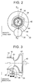
- FIG. 2 is a schematic view on Arrow A in FIG. 1 .
- the compressor 20 includes a housing 34 that constitutes an outer shell of the compressor 20 and has a substantially circular shape in front view, a flange 36 that is provided in a center portion of the housing 34, and an air bypass valve (ABV) 38 that is provided in an outer peripheral portion of the housing 34.
- An impeller 42 that is installed so as to be rotatable about a shaft 40 is accommodated in the housing 34.
- the ABV 38 is a normally-closed solenoid valve, and is provided in a lower portion in a gravity direction (a vertical direction).
- FIG. 3 is a schematic view on Arrow BB in FIG 2 .
- the groove 44 is formed in an outer peripheral portion of an inlet 46 that guides a gas to a suction side of the impeller 42.
- a portion of the groove 44 communicates with an air outlet portion of an air bypass passage 48 that is partially closed by the ABV 38.
- An air inlet portion of the air bypass passage 48 communicates with a scroll (not shown) of the housing 34. That is, the air bypass passage is formed within the housing 34.
- the LP circuit EGR system includes an ECU (Electronic Control Unit) 50 as a control device.
- An airflow meter 52 that detects a flow rate and a temperature of an intake gas (fresh air) flowing into the intake passage 18, a throttle position sensor 54 that detects an opening of the throttle valve 24, an EGR position sensor 56 that detects an opening of the EGR valve 32, and other various sensors necessary for controlling the engine 10 (for example, a temperature sensor that detects an engine cooling water temperature, and a crank angle sensor that detects an engine speed) are electrically connected to an input side of the ECU 50.
- the throttle valve 24, the EGR valve 32, the ABV 38, and other various actuators are electrically connected to an output side of the ECU 50.
- the ECU 50 executes predetermined programs based on input information from the various sensors described above to operate the various actuators or the like described above, and thereby executes erosion measure ABV operation control described below, and other various controls regarding an operation of the engine 10.
- FIG. 4 is a view for explaining a problem in a conventional LP circuit EGR system.
- condensed water may be generated in an intake passage 62 on an upstream side of an impeller 60. This is because water vapor in an EGR gas is cooled by an inner wall of the intake passage 62 or fresh air, and the condensed water is easily generated especially when an outside air temperature is low.
- the condensed water generated by contact with the fresh air flows through center portions of the intake passage 62 and an inlet 64, and flows into the impeller 60 from a center portion of the impeller 60 (that is, near a shaft 66).
- the condensed water generated by contact with the inner wall of the intake passage 62 or generated by contact with the fresh air and adhering to the inner wall moves along the inner wall.
- the condensed water moving along the inner wall moves to an inner wall of the inlet 64 while increasing its size, and comes into contact with an outer peripheral portion 60a of a front end surface of the impeller 60. Accordingly, erosion occurs in the outer peripheral portion 60a, resulting in a problem that boost efficiency is reduced.
- condensed water moving along an inner wall of the intake passage 18 can be collected in the groove 44. Therefore, damage to an outer peripheral portion of a front end surface of the impeller 42 by contact with the condensed water can be prevented.
- the groove 44 has a limited capacity, there remains a possibility that the condensed water overflows from the groove 44.
- the condensed water is continuously accumulated in the groove 44 for a long time, an area around the groove 44 may be eroded.
- control is performed in which the condensed water is discharged from the groove 44 by operating the ABV 38 while the condensed water is being collected in the groove 44 (the erosion measure ABV operation control).
- the erosion measure ABV operation control is control for opening the ABV 38 when an operating condition of the ABV 38 and a condensed water generation condition are satisfied.
- the above operating condition is a normal operating condition of the ABV 38, and is satisfied when the throttle valve 24 is rapidly closed during high boosting.
- a reason why the ABV 38 is opened when the above operating condition is satisfied is because, when the throttle valve 24 is rapidly closed during high boosting, a pressure on the downstream side of the impeller 42 is increased, turbo rotation is slowed down, and engine torque is not outputted in next acceleration, so that the vehicle or the like cannot be driven as intended by a driver.
- the above condensed water generation condition is a characteristic condition of the present embodiment, and is satisfied when the condensed water is generated on or adheres to the inner wall of the intake passage 18 on the upstream side of the impeller 42.
- the scroll and the groove 44 can be brought into communication, and the condensed water collected in the groove 44 can be discharged.
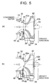
- FIG. 5 is a view for explaining the erosion measure ABV operation control.
- the condensed water is sometimes generated on the inner wall of the intake passage 18 on the upstream side of the impeller 42 similarly to the conventional system described using FIG. 4 .
- the generated condensed water can be caused to flow into the groove 44, and can be temporarily accumulated therein ( FIG. 5(a) ).
- the condensed water flowing into the groove 44 moves to the lower portion in the gravity direction (that is, to the ABV 38-side) in the groove 44 ( FIG. 5(a) ).
- the condensed water accumulated in the groove 44 on the ABV 38-side is discharged ( FIG. 5(b) ).
- the condensed water accumulated in the groove 44 on the ABV 38-side is blown away to a center portion of the inlet 46 on a flow of the return gas directed from the downstream side to the upstream side of the impeller 42, and, together with the intake gas flowing through the center portion, the condensed water flows into the compressor 20 from a center portion 42b (that is, near the shaft 40) of the front end surface of the impeller 42 ( FIG. 5(b) ).
- the center portion 42b has a lower circumferential speed than that of an outer peripheral portion 42a at the front end surface of the impeller 42, the erosion by contact with the condensed water is difficult to occur as compared to the outer peripheral portion 42a. That is, the occurrence of the erosion in the impeller 42 can be suppressed.
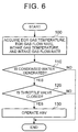
- FIG. 6 is a flowchart illustrating a processing routine of the erosion measure ABV operation control executed by the ECU 50 in the present embodiment. Note that the routine shown in FIG. 6 is repeatedly executed when a boost pressure reaches a set value or more.
- the ECU 50 acquires a temperature and a flow rate of the EGR gas and a temperature and a flow rate of the intake gas (step 100).
- the temperature of the EGR gas is calculated by using a model or the like separately stored in the ECU 50.
- the flow rate of the EGR gas is calculated from a signal of the EGR position sensor 56.
- the temperature and the flow rate of the intake gas are calculated from a signal of the airflow meter 52.
- the ECU 50 determines whether the above condensed water generation condition is satisfied by using the values acquired in step 100 (step 110). To be more specific, the ECU 50 first calculates a temperature of the inner wall of the intake passage 18 on the upstream side of the impeller 42, and calculates a dew point temperature of a mixture gas of the EGR gas and the intake gas by using the values acquired in step 100. When the inner wall temperature falls below the dew point temperature, it can be determined that the condensed water is generated on or adheres to the inner wall, so that the ECU 50 proceeds to step 120. On the other hand, when the inner wall temperature is equal to or more than the dew point temperature, it can be determined that the above condensed water generation condition is not satisfied, so that the ECU 50 terminates the routine.
- step 120 the ECU 50 determines whether the above operating condition is satisfied.
- the ECU 50 determines whether the above operating condition is satisfied by using a gradient of the throttle opening from a signal of the throttle position sensor 54.
- an absolute value of the above gradient exceeds a predetermined reference value, it can be determined that the throttle valve 24 is rapidly closed, so that the ECU 50 proceeds to step 130, and operates the ABV 38.
- the absolute value of the above gradient is equal to or less than the predetermined reference value, it can be determined that the above operating condition is not satisfied, so that the ECU 50 terminates the routine.
- the ABV 38 can be operated. Therefore, the condensed water collected in the groove 44 on the ABV 38-side can be discharged by the return gas, brought into contact with the center portion 42b, and then caused to flow into the impeller 42. Thus, the occurrence of the erosion in the outer peripheral portion 42a of the impeller 42 can be suppressed.
- the EGR passage 26 corresponds to an "exhaust gas recirculation passage" of the above first invention, the compressor 20 a “compressor” of the same invention, the groove 44 a “storage portion” of the same invention, and the air bypass passage 48 a "bypass passage” of the same invention.
- the air outlet portion of the air bypass passage 48 corresponds to a "connection portion" of the above second invention.
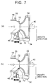
- FIG. 7 is a view for explaining modifications of the present embodiment.
- a groove 70 may be formed in a direction parallel to the flow direction of the intake gas ( FIG. 7(a) ).
- a groove 72 may be formed along an inclination direction of the inlet 46 ( FIG. 7(b) ). Since the grooves 70, 72 can temporarily store the condensed water generated or the like on the inner wall of the intake passage 18, an effect similar to that of the above embodiment can be obtained.
- FIG. 8 is a view for explaining a modification of the present embodiment.
- a diameter of an inlet 76 is substantially constant from the intake passage 18-side up to an inner wall 78, and is decreased on a downstream side with respect to the inner wall 78.
- the inner wall 78 forms a surface parallel to the front end surface of the impeller 42, and is formed so as to surround the outer peripheral portion of the front end surface. Therefore, as shown in FIG.
- FIG. 9 is a view for explaining a modification of the present embodiment. Even when an air outlet portion 80 having a plurality of return portions 80a to 80d is provided in an outer periphery of the groove 44 as shown in FIG. 9 , the condensed water accumulated in the groove 44 can be discharged by the return gas, and caused to flow into the impeller 42 from the center portion of the impeller 42. Therefore, the effect similar to that of the above embodiment can be obtained.
- the air bypass passage 48 and the groove 44 are formed within the housing 34 in the above embodiments, the air bypass passage 48 and the groove 44 may be formed outside of the housing 34. That is, the air bypass passage 48 and the groove 44 may be formed in the inner wall of the intake passage 18 between a gas outlet portion of the EGR passage 26 and the impeller 42.
Landscapes
- Engineering & Computer Science (AREA)
- Chemical & Material Sciences (AREA)
- Combustion & Propulsion (AREA)
- Mechanical Engineering (AREA)
- General Engineering & Computer Science (AREA)
- Chemical Kinetics & Catalysis (AREA)
- Exhaust-Gas Circulating Devices (AREA)
- Supercharger (AREA)
Abstract
Description
- The present invention relates to an exhaust gas recirculation system for an internal combustion engine. More particularly, the present invention relates to an exhaust gas recirculation (EGR) system that is applied to a supercharged internal combustion engine.
- Conventionally, application of an EGR system to a supercharged internal combustion engine is known as disclosed in, for example, Patent Literature 1. The EGR system constitutes a low pressure (LP) circuit EGR system. The LP circuit EGR system recirculates a low-pressure exhaust gas to the internal combustion engine by connecting an exhaust passage on a downstream side of an exhaust turbine, and an intake passage on an upstream side of a compressor. In accordance with the LP circuit EGR system, an EGR gas can be introduced into an intake gas that has not been boosted yet, a large amount of EGR gas can be recirculated to the internal combustion engine.
- On the other hand, the LP circuit EGR system has a problem that the EGR gas is cooled to generate condensed water when the EGR gas joins the intake gas. When the condensed water is generated, erosion is caused to occur in an impeller of the compressor. In this regard, the EGR system of Patent Literature 1 includes an EGR heater that heats the EGR gas to a predetermined temperature in an EGR passage. When the EGR heater is operated, a temperature of the EGR gas can be increased before the EGR gas joins the intake gas. Therefore, the occurrence of the erosion can be suppressed by reducing an amount of the condensed water on the upstream side of the compressor.
- Patent Literature 1: Japanese Patent Application Publication No.
2009-174444 - However, the above EGR heater is for heating only, and when the EGR heater is installed, problems of a cost increase and ensuring of a space are unavoidable. Also, since a pressure loss in the above EGR heater is increased, an advantage of the LP circuit EGR system that the large amount of EGR gas can be recirculated to the internal combustion engine is possibly impaired.
- The present invention has been made in view of the above problems. That is, an object is to provide an exhaust gas recirculation system for an internal combustion engine that can suppress occurrence of erosion in a compressor impeller by using an existing system.
- In order to achieve the above object, a first invention is an exhaust gas recirculation system for an internal combustion engine, the exhaust gas recirculation system including:
- an exhaust gas recirculation passage that connects an intake passage and an exhaust passage of the internal combustion engine;
- a compressor that is provided downstream of a connection portion of the intake passage with the exhaust gas recirculation passage, and accommodates an impeller;
- a storage portion that is formed in an inner wall of the intake passage between the connection portion and the impeller, and stores condensed water generated upstream of the compressor; and
- a bypass passage that communicates with the storage portion, and bypasses the impeller to return an intake gas from a downstream side to an upstream side of the impeller.
- Also, in a second invention according to the first invention,
a connection portion of the bypass passage with the storage portion is provided below the center of a rotating shaft of the impeller. The "below the center of a rotating shaft of the impeller" means a position lower than the center of the rotating shaft of the impeller. The "below the center of a rotating shaft of the impeller" includes not only a region immediately below (vertically below) the center of the rotating shaft of the impeller, but also a region on a lower side of the center of the rotating shaft and on an outer side of the region. - Also, in a third invention according to the first or second invention,
the storage portion is formed within the compressor. - Also, in a fourth invention according to any one of the first to third inventions,
the storage portion is an annular groove that is formed so as to surround the intake passage. - When the condensed water generated upstream of the compressor comes into contact with an outer peripheral portion of a front end surface of the impeller, erosion occurs in the outer peripheral portion. In this regard, in accordance with the first invention, the condensed water can be accumulated in the storage portion. The storage portion is formed in the inner wall of the intake passage between the connection portion of the intake passage with the exhaust gas recirculation passage and the impeller, and communicates with the bypass passage that bypasses the impeller to return the intake gas from the downstream side to the upstream side of the impeller. Therefore, the condensed water accumulated in the storage portion can be discharged, blown away to a center portion of the intake passage, and brought into contact with a center portion of the front end surface of the impeller by the intake gas returned to the upstream side from the downstream side of the impeller,. Since the center portion has a lower circumferential speed than that of the outer peripheral portion at the front end surface of the impeller, the erosion by contact with the condensed water is difficult to occur in the center portion. Also, the bypass passage is generally provided in a supercharged internal combustion engine. Therefore, in accordance with the first invention, the occurrence of the erosion in the impeller of the compressor can be suppressed by using an existing system.
- In accordance with the second invention, since the connection portion of the bypass passage with the storage portion is provided below the center of the rotating shaft of the impeller, the condensed water discharged from the storage portion can be blown away to the center portion of the intake passage.
- In accordance with the third invention, since the storage portion is formed within the compressor, the condensed water can be accumulated directly upstream of the impeller. Also, since a moving distance in which the condensed water discharged from the storage portion reaches the impeller can be shortened, contact energy when the condensed water comes into contact with the impeller can be reduced. Therefore, the occurrence of the erosion in the impeller of the compressor can be further suppressed.
- In accordance with the fourth invention, the condensed water generated upstream of the compressor can be accumulated in the annular groove formed so as to surround the intake passage.
-
- [
FIG. 1] FIG. 1 is a view for explaining a configuration of an LP circuit EGR system of an embodiment. - [
FIG. 2] FIG. 2 is a schematic view on Arrow A inFIG. 1 . - [
FIG. 3] FIG. 3 is a schematic view on Arrow BB inFIG 2 . - [
FIG. 4] FIG. 4 is a view for explaining a problem in a conventional LP circuit EGR system. - [
FIG. 5] FIG. 5 is a view for explaining erosion measure ABV operation control. - [
FIG. 6] FIG. 6 is a flowchart illustrating a processing routine of the erosion measure ABV operation control executed by an ECU 50 in the embodiment. - [
FIG. 7] FIG. 7 is a view for explaining modifications of the embodiment. - [
FIG. 8] FIG. 8 is a view for explaining a modification of the embodiment. - [
FIG. 9] FIG. 9 is a view for explaining a modification of the embodiment. - Hereinafter, embodiments of the present invention will be described in detail by reference to the drawings. Note that common elements in the respective drawings are assigned the same reference numerals, and an overlapping description is omitted.
-
FIG. 1 is a view for explaining a configuration of an LP circuit EGR system of the present embodiment. As shown inFIG. 1 , the LP circuit EGR system includes anengine 10 as an internal combustion engine that is mounted on a vehicle or the like. Each cylinder of theengine 10 is provided with a piston, an intake valve, an exhaust valve, a fuel injector, or the like. Although theengine 10 is shown as an inline-four engine inFIG. 1 , the number of cylinders and a cylinder arrangement of theengine 10 are not limited thereto. - The LP circuit EGR system includes a
supercharger 12. Thesupercharger 12 includes aturbine 16 that is provided in anexhaust passage 14, and acompressor 20 that is provided in anintake passage 18. Theturbine 16 and thecompressor 20 are connected to each other. When thesupercharger 12 is operated, theturbine 16 rotates upon receiving an exhaust pressure, so that thecompressor 20 is driven, and a gas flowing into thecompressor 20 is compressed. Theintake passage 18 is provided with anintercooler 22 that cools the compressed gas. Athrottle valve 24 is provided downstream of theintercooler 22. - The LP circuit EGR system includes an
EGR passage 26 through which an exhaust gas flowing through theexhaust passage 14 is introduced into theintake passage 18. TheEGR passage 26 connects theexhaust passage 14 on a downstream side of an exhaustgas treatment device 28 and theintake passage 18 on an upstream side of thecompressor 20. AnEGR cooler 30 that cools the exhaust gas flowing through the EGR passage 26 (that is, an EGR gas) is provided midway in theEGR passage 26. AnEGR valve 32 that controls a flow rate of the EGR gas to be introduced into theintake passage 18 is attached to theEGR cooler 30. -
FIG. 2 is a schematic view on Arrow A inFIG. 1 . As shown inFIG. 2 , thecompressor 20 includes ahousing 34 that constitutes an outer shell of thecompressor 20 and has a substantially circular shape in front view, aflange 36 that is provided in a center portion of thehousing 34, and an air bypass valve (ABV) 38 that is provided in an outer peripheral portion of thehousing 34. Animpeller 42 that is installed so as to be rotatable about ashaft 40 is accommodated in thehousing 34. TheABV 38 is a normally-closed solenoid valve, and is provided in a lower portion in a gravity direction (a vertical direction). - An
annular groove 44 is formed in thehousing 34 between theflange 36 and theimpeller 42.FIG. 3 is a schematic view on Arrow BB inFIG 2 . As shown inFIG. 3 , thegroove 44 is formed in an outer peripheral portion of aninlet 46 that guides a gas to a suction side of theimpeller 42. A portion of thegroove 44 communicates with an air outlet portion of anair bypass passage 48 that is partially closed by theABV 38. An air inlet portion of theair bypass passage 48 communicates with a scroll (not shown) of thehousing 34. That is, the air bypass passage is formed within thehousing 34. By opening theABV 38, the closing of theair bypass passage 48 is released, and the scroll and theair bypass passage 48 come into communication with each other. When theABV 38 is opened during boosting, a compressed gas on a downstream side of theimpeller 42 is returned to an upstream side of theimpeller 42 due to a pressure difference between the upstream side and the downstream side of theimpeller 42. - The system configuration continues to be described by referring back to
FIG. 1 . The LP circuit EGR system includes an ECU (Electronic Control Unit) 50 as a control device. Anairflow meter 52 that detects a flow rate and a temperature of an intake gas (fresh air) flowing into theintake passage 18, athrottle position sensor 54 that detects an opening of thethrottle valve 24, anEGR position sensor 56 that detects an opening of theEGR valve 32, and other various sensors necessary for controlling the engine 10 (for example, a temperature sensor that detects an engine cooling water temperature, and a crank angle sensor that detects an engine speed) are electrically connected to an input side of the ECU 50. On the other hand, thethrottle valve 24, theEGR valve 32, theABV 38, and other various actuators are electrically connected to an output side of the ECU 50. The ECU 50 executes predetermined programs based on input information from the various sensors described above to operate the various actuators or the like described above, and thereby executes erosion measure ABV operation control described below, and other various controls regarding an operation of theengine 10. -
FIG. 4 is a view for explaining a problem in a conventional LP circuit EGR system. As shown inFIG. 4 , in the conventional system, condensed water may be generated in anintake passage 62 on an upstream side of animpeller 60. This is because water vapor in an EGR gas is cooled by an inner wall of theintake passage 62 or fresh air, and the condensed water is easily generated especially when an outside air temperature is low. The condensed water generated by contact with the fresh air flows through center portions of theintake passage 62 and aninlet 64, and flows into theimpeller 60 from a center portion of the impeller 60 (that is, near a shaft 66). On the other hand, the condensed water generated by contact with the inner wall of theintake passage 62 or generated by contact with the fresh air and adhering to the inner wall moves along the inner wall. The condensed water moving along the inner wall moves to an inner wall of theinlet 64 while increasing its size, and comes into contact with an outerperipheral portion 60a of a front end surface of theimpeller 60. Accordingly, erosion occurs in the outerperipheral portion 60a, resulting in a problem that boost efficiency is reduced. - In this regard, in accordance with the LP circuit EGR system of the present embodiment, condensed water moving along an inner wall of the
intake passage 18 can be collected in thegroove 44. Therefore, damage to an outer peripheral portion of a front end surface of theimpeller 42 by contact with the condensed water can be prevented. However, since thegroove 44 has a limited capacity, there remains a possibility that the condensed water overflows from thegroove 44. When the condensed water is continuously accumulated in thegroove 44 for a long time, an area around thegroove 44 may be eroded. Thus, in the present embodiment, control is performed in which the condensed water is discharged from thegroove 44 by operating theABV 38 while the condensed water is being collected in the groove 44 (the erosion measure ABV operation control). - The erosion measure ABV operation control is control for opening the
ABV 38 when an operating condition of theABV 38 and a condensed water generation condition are satisfied. The above operating condition is a normal operating condition of theABV 38, and is satisfied when thethrottle valve 24 is rapidly closed during high boosting. A reason why theABV 38 is opened when the above operating condition is satisfied is because, when thethrottle valve 24 is rapidly closed during high boosting, a pressure on the downstream side of theimpeller 42 is increased, turbo rotation is slowed down, and engine torque is not outputted in next acceleration, so that the vehicle or the like cannot be driven as intended by a driver. Also, the above condensed water generation condition is a characteristic condition of the present embodiment, and is satisfied when the condensed water is generated on or adheres to the inner wall of theintake passage 18 on the upstream side of theimpeller 42. By opening theABV 38 when the above condensed water generation condition is satisfied, the scroll and thegroove 44 can be brought into communication, and the condensed water collected in thegroove 44 can be discharged. -
FIG. 5 is a view for explaining the erosion measure ABV operation control. In the LP circuit EGR system of the present embodiment, the condensed water is sometimes generated on the inner wall of theintake passage 18 on the upstream side of theimpeller 42 similarly to the conventional system described usingFIG. 4 . In this regard, in accordance with the present embodiment, the generated condensed water can be caused to flow into thegroove 44, and can be temporarily accumulated therein (FIG. 5(a) ). The condensed water flowing into thegroove 44 moves to the lower portion in the gravity direction (that is, to the ABV 38-side) in the groove 44 (FIG. 5(a) ). - When the erosion measure ABV operation control is executed, the condensed water accumulated in the
groove 44 on the ABV 38-side is discharged (FIG. 5(b) ). The condensed water accumulated in thegroove 44 on the ABV 38-side is blown away to a center portion of theinlet 46 on a flow of the return gas directed from the downstream side to the upstream side of theimpeller 42, and, together with the intake gas flowing through the center portion, the condensed water flows into thecompressor 20 from acenter portion 42b (that is, near the shaft 40) of the front end surface of the impeller 42 (FIG. 5(b) ). Since thecenter portion 42b has a lower circumferential speed than that of an outerperipheral portion 42a at the front end surface of theimpeller 42, the erosion by contact with the condensed water is difficult to occur as compared to the outerperipheral portion 42a. That is, the occurrence of the erosion in theimpeller 42 can be suppressed. -
FIG. 6 is a flowchart illustrating a processing routine of the erosion measure ABV operation control executed by the ECU 50 in the present embodiment. Note that the routine shown inFIG. 6 is repeatedly executed when a boost pressure reaches a set value or more. - In the routine shown in
FIG. 6 , first, the ECU 50 acquires a temperature and a flow rate of the EGR gas and a temperature and a flow rate of the intake gas (step 100). In this step, the temperature of the EGR gas is calculated by using a model or the like separately stored in the ECU 50. The flow rate of the EGR gas is calculated from a signal of theEGR position sensor 56. The temperature and the flow rate of the intake gas are calculated from a signal of theairflow meter 52. - Subsequently, the ECU 50 determines whether the above condensed water generation condition is satisfied by using the values acquired in step 100 (step 110). To be more specific, the ECU 50 first calculates a temperature of the inner wall of the
intake passage 18 on the upstream side of theimpeller 42, and calculates a dew point temperature of a mixture gas of the EGR gas and the intake gas by using the values acquired instep 100. When the inner wall temperature falls below the dew point temperature, it can be determined that the condensed water is generated on or adheres to the inner wall, so that the ECU 50 proceeds to step 120. On the other hand, when the inner wall temperature is equal to or more than the dew point temperature, it can be determined that the above condensed water generation condition is not satisfied, so that the ECU 50 terminates the routine. - In
step 120, the ECU 50 determines whether the above operating condition is satisfied. To be more specific, the ECU 50 determines whether the above operating condition is satisfied by using a gradient of the throttle opening from a signal of thethrottle position sensor 54. When an absolute value of the above gradient exceeds a predetermined reference value, it can be determined that thethrottle valve 24 is rapidly closed, so that the ECU 50 proceeds to step 130, and operates theABV 38. On the other hand, when the absolute value of the above gradient is equal to or less than the predetermined reference value, it can be determined that the above operating condition is not satisfied, so that the ECU 50 terminates the routine. - As described above, in accordance with the routine shown in
FIG. 6 , when the inner wall temperature of theintake passage 18 falls below the dew point temperature, and the absolute value of the gradient of the throttle opening exceeds the predetermined reference value, theABV 38 can be operated. Therefore, the condensed water collected in thegroove 44 on the ABV 38-side can be discharged by the return gas, brought into contact with thecenter portion 42b, and then caused to flow into theimpeller 42. Thus, the occurrence of the erosion in the outerperipheral portion 42a of theimpeller 42 can be suppressed. - Note that in the above embodiment, the
EGR passage 26 corresponds to an "exhaust gas recirculation passage" of the above first invention, the compressor 20 a "compressor" of the same invention, the groove 44 a "storage portion" of the same invention, and the air bypass passage 48 a "bypass passage" of the same invention. - Also, the air outlet portion of the
air bypass passage 48 corresponds to a "connection portion" of the above second invention. - By the way, although the
groove 44 is formed in a direction perpendicular to a flow direction of the intake gas in the above embodiment, a formation direction of thegroove 44 is not limited thereto, and various modifications may be made.FIG. 7 is a view for explaining modifications of the present embodiment. For example, agroove 70 may be formed in a direction parallel to the flow direction of the intake gas (FIG. 7(a) ). Alternatively, agroove 72 may be formed along an inclination direction of the inlet 46 (FIG. 7(b) ). Since thegrooves intake passage 18, an effect similar to that of the above embodiment can be obtained. - Furthermore, a housing that can temporarily store the condensed water can produce the effect similar to that of the above embodiment.
FIG. 8 is a view for explaining a modification of the present embodiment. In ahousing 74 shown inFIG. 8 , a diameter of aninlet 76 is substantially constant from the intake passage 18-side up to aninner wall 78, and is decreased on a downstream side with respect to theinner wall 78. Theinner wall 78 forms a surface parallel to the front end surface of theimpeller 42, and is formed so as to surround the outer peripheral portion of the front end surface. Therefore, as shown inFIG. 8 , the condensed water moving along the inner wall of theintake passage 18 is blocked by theinner wall 78, and is temporarily stored in the lower portion in the gravity direction (that is, the air bypass passage 48-side). Thus, when a blocking portion as described above is formed in the housing, the effect similar to that of the above embodiment can be obtained. - Also, although the
ABV 38 is provided in the lower portion in the gravity direction, and the air outlet portion of theair bypass passage 48 is connected to thegroove 44 from the lower portion in the gravity direction in the above embodiment, a method of connecting the air outlet portion to thegroove 44 and a position of theABV 38 are not limited thereto, and various modifications may be made.FIG. 9 is a view for explaining a modification of the present embodiment. Even when anair outlet portion 80 having a plurality ofreturn portions 80a to 80d is provided in an outer periphery of thegroove 44 as shown inFIG. 9 , the condensed water accumulated in thegroove 44 can be discharged by the return gas, and caused to flow into theimpeller 42 from the center portion of theimpeller 42. Therefore, the effect similar to that of the above embodiment can be obtained. - Also, although the
air bypass passage 48 and thegroove 44 are formed within thehousing 34 in the above embodiments, theair bypass passage 48 and thegroove 44 may be formed outside of thehousing 34. That is, theair bypass passage 48 and thegroove 44 may be formed in the inner wall of theintake passage 18 between a gas outlet portion of theEGR passage 26 and theimpeller 42. - 10 Engine, 12 Supercharger, 14 Exhaust passage, 18, 62 Intake passage, 20 Compressor, 24 Throttle valve, 26 EGR passage, 34, 74 Housing, 38 Air bypass valve (ABV), 42, 60 Impeller, 44, 70, 72 Groove, 46, 64, 76 Inlet, 48 Air bypass passage, 50 ECU
Claims (4)
- An exhaust gas recirculation system for an internal combustion engine, the exhaust gas recirculation system comprising:an exhaust gas recirculation passage that connects an intake passage and an exhaust passage of the internal combustion engine;a compressor that is provided downstream of a connection portion of the intake passage with the exhaust gas recirculation passage, and accommodates an impeller;a storage portion that is formed in an inner wall of the intake passage between the connection portion and the impeller, and stores condensed water generated upstream of the compressor; anda bypass passage that communicates with the storage portion, and bypasses the impeller to return an intake gas from a downstream side to an upstream side of the impeller.
- The exhaust gas recirculation system for an internal combustion engine according to claim 1,
wherein a connection portion of the bypass passage with the storage portion is provided below the center of a rotating shaft of the impeller. - The exhaust gas recirculation system for an internal combustion engine according to claim 1 or 2,
wherein the storage portion is formed within the compressor. - The exhaust gas recirculation system for an internal combustion engine according to any one of claims 1 to 3,
wherein the storage portion is an annular groove that is formed so as to surround the intake passage.
Applications Claiming Priority (1)
| Application Number | Priority Date | Filing Date | Title |
|---|---|---|---|
| PCT/JP2013/067477 WO2014207831A1 (en) | 2013-06-26 | 2013-06-26 | Exhaust recirculation device for internal combustion engine |
Publications (3)
| Publication Number | Publication Date |
|---|---|
| EP3015675A1 true EP3015675A1 (en) | 2016-05-04 |
| EP3015675A4 EP3015675A4 (en) | 2016-08-03 |
| EP3015675B1 EP3015675B1 (en) | 2017-10-04 |
Family
ID=52141238
Family Applications (1)
| Application Number | Title | Priority Date | Filing Date |
|---|---|---|---|
| EP13888195.8A Not-in-force EP3015675B1 (en) | 2013-06-26 | 2013-06-26 | Exhaust recirculation device for internal combustion engine |
Country Status (5)
| Country | Link |
|---|---|
| US (1) | US10006414B2 (en) |
| EP (1) | EP3015675B1 (en) |
| JP (1) | JP5825434B2 (en) |
| CN (1) | CN105339624B (en) |
| WO (1) | WO2014207831A1 (en) |
Cited By (1)
| Publication number | Priority date | Publication date | Assignee | Title |
|---|---|---|---|---|
| GB2565292A (en) * | 2017-08-07 | 2019-02-13 | Ford Global Tech Llc | A Condensate management device for a turbocharged engine |
Families Citing this family (9)
| Publication number | Priority date | Publication date | Assignee | Title |
|---|---|---|---|---|
| DE102015016030A1 (en) | 2015-12-11 | 2017-06-14 | Man Truck & Bus Ag | Exhaust gas turbocharger for a motor vehicle |
| US10323607B2 (en) * | 2016-07-14 | 2019-06-18 | Ge Global Sourcing Llc | Method and systems for draining fluid from an engine |
| CN106499549B (en) * | 2016-11-30 | 2018-09-11 | 安徽江淮汽车集团股份有限公司 | A kind of EGR draft tube structures |
| DE102017210648A1 (en) | 2017-06-23 | 2018-12-27 | Ford Global Technologies, Llc | Condensate trap in a compressor inlet |
| JP6455581B1 (en) * | 2017-11-17 | 2019-01-23 | マツダ株式会社 | ENGINE CONTROL DEVICE AND ENGINE CONTROL METHOD |
| CN110374765A (en) * | 2018-04-12 | 2019-10-25 | 罗伯特·博世有限公司 | Scheme for exhaust gas circulation system and its engine with gas fuel |
| DE102018111560B4 (en) * | 2018-05-15 | 2025-12-31 | Volkswagen Aktiengesellschaft | Compressor with trimmer and drainage pipe and internal combustion engine with such a compressor |
| US20200025157A1 (en) * | 2018-07-17 | 2020-01-23 | GM Global Technology Operations LLC | Exhaust gas recirculation system and method of operating the same |
| ES2875173B2 (en) * | 2021-03-11 | 2023-06-15 | Univ Valencia Politecnica | DEVICE AND PROCEDURE FOR EMULATION OF SUPERCHARGING SYSTEMS |
Family Cites Families (14)
| Publication number | Priority date | Publication date | Assignee | Title |
|---|---|---|---|---|
| WO2007089567A1 (en) * | 2006-01-27 | 2007-08-09 | Borgwarner Inc. | Re-introduction unit for lp-egr condensate at/before the compressor |
| CN101371029A (en) * | 2006-01-27 | 2009-02-18 | 博格华纳公司 | Mixing unit for LP-EGR condensate to enter the compressor |
| DE202007005986U1 (en) * | 2007-04-24 | 2008-09-04 | Mann+Hummel Gmbh | Combustion air and exhaust gas arrangement of an internal combustion engine |
| JP5018400B2 (en) * | 2007-06-21 | 2012-09-05 | トヨタ自動車株式会社 | Exhaust gas recirculation device for internal combustion engine |
| JP2009174444A (en) | 2008-01-25 | 2009-08-06 | Honda Motor Co Ltd | EGR device |
| US20090241515A1 (en) * | 2008-03-26 | 2009-10-01 | Denso International America, Inc. | Exhaust condensation separator |
| JP2009264339A (en) * | 2008-04-28 | 2009-11-12 | Toyota Motor Corp | Exhaust recirculation device of internal combustion engine |
| JP2009270524A (en) * | 2008-05-09 | 2009-11-19 | Toyota Motor Corp | Internal combustion engine with supercharger |
| JP2012149588A (en) * | 2011-01-20 | 2012-08-09 | Denso Corp | Controller for internal combustion engine |
| JP5708507B2 (en) * | 2012-01-18 | 2015-04-30 | トヨタ自動車株式会社 | Compressor deposit cleaning device for internal combustion engine |
| WO2014170954A1 (en) * | 2013-04-16 | 2014-10-23 | トヨタ自動車株式会社 | Compressor for exhaust-gas turbo-supercharger |
| JP2014231821A (en) * | 2013-05-30 | 2014-12-11 | トヨタ自動車株式会社 | Controller for internal combustion engine equipped with supercharger |
| JP6206163B2 (en) * | 2013-12-20 | 2017-10-04 | トヨタ自動車株式会社 | Internal combustion engine control system |
| JP6070587B2 (en) * | 2014-01-22 | 2017-02-01 | トヨタ自動車株式会社 | Internal combustion engine |
-
2013
- 2013-06-26 EP EP13888195.8A patent/EP3015675B1/en not_active Not-in-force
- 2013-06-26 US US14/392,136 patent/US10006414B2/en active Active
- 2013-06-26 CN CN201380077777.1A patent/CN105339624B/en not_active Expired - Fee Related
- 2013-06-26 JP JP2014521382A patent/JP5825434B2/en not_active Expired - Fee Related
- 2013-06-26 WO PCT/JP2013/067477 patent/WO2014207831A1/en not_active Ceased
Cited By (3)
| Publication number | Priority date | Publication date | Assignee | Title |
|---|---|---|---|---|
| GB2565292A (en) * | 2017-08-07 | 2019-02-13 | Ford Global Tech Llc | A Condensate management device for a turbocharged engine |
| GB2565292B (en) * | 2017-08-07 | 2019-08-21 | Ford Global Tech Llc | A condensate management device for a turbocharged engine |
| US10794338B2 (en) | 2017-08-07 | 2020-10-06 | Ford Global Technologies, Llc | Condensate management device for a turbocharged engine |
Also Published As
| Publication number | Publication date |
|---|---|
| EP3015675A4 (en) | 2016-08-03 |
| JP5825434B2 (en) | 2015-12-02 |
| WO2014207831A1 (en) | 2014-12-31 |
| CN105339624A (en) | 2016-02-17 |
| CN105339624B (en) | 2018-06-05 |
| EP3015675B1 (en) | 2017-10-04 |
| JPWO2014207831A1 (en) | 2017-02-23 |
| US10006414B2 (en) | 2018-06-26 |
| US20160186701A1 (en) | 2016-06-30 |
Similar Documents
| Publication | Publication Date | Title |
|---|---|---|
| EP3015675B1 (en) | Exhaust recirculation device for internal combustion engine | |
| CN102072011B (en) | Multi-stage turbocharger system and method | |
| JP5527486B2 (en) | Ventilation control device for internal combustion engine | |
| CN204267177U (en) | The compressor of turbosupercharger | |
| CN105464789B (en) | Twin-scroll turbocharger device for internal combustion engine and control method thereof | |
| US8820071B2 (en) | Integrated compressor housing and inlet | |
| CN103835819B (en) | The control device of internal combustion engine and control method | |
| CN105324558B (en) | Engine system with intake bypass | |
| US9765712B2 (en) | System and method for turbocharger compressor surge control | |
| JP4746389B2 (en) | Supercharging system | |
| JP2012052508A (en) | Variable supercharger and control method thereof | |
| CN106481444A (en) | Adjust method and the explosive motor of explosive motor the blowing pressure | |
| JP2008045411A (en) | Control device for an internal combustion engine with a supercharger | |
| JP2012067614A (en) | Device for controlling compressor outlet pressure | |
| US20110283977A1 (en) | Control apparatus for internal combustion engine with supercharger | |
| US10145297B2 (en) | Control device for engine equipped with turbo-supercharger | |
| US10018162B2 (en) | Driving device for driving a vehicle as well as method and computer program product for operating this driving device | |
| US10787955B2 (en) | Two-stage turbo system and control method for two-stage turbo system | |
| WO2015098391A1 (en) | Exhaust gas recirculation apparatus for internal combustion engine with supercharger | |
| JP5682245B2 (en) | Low pressure loop EGR device | |
| JP7413734B2 (en) | Gas flow rate calculation method | |
| JP2022062878A (en) | Engine system and control method | |
| JP2009108680A (en) | Supercharger for internal combustion engine | |
| JP4816514B2 (en) | Internal combustion engine with a supercharger | |
| JP2010203329A (en) | Control method |
Legal Events
| Date | Code | Title | Description |
|---|---|---|---|
| PUAI | Public reference made under article 153(3) epc to a published international application that has entered the european phase |
Free format text: ORIGINAL CODE: 0009012 |
|
| 17P | Request for examination filed |
Effective date: 20151223 |
|
| AK | Designated contracting states |
Kind code of ref document: A1 Designated state(s): AL AT BE BG CH CY CZ DE DK EE ES FI FR GB GR HR HU IE IS IT LI LT LU LV MC MK MT NL NO PL PT RO RS SE SI SK SM TR |
|
| AX | Request for extension of the european patent |
Extension state: BA ME |
|
| A4 | Supplementary search report drawn up and despatched |
Effective date: 20160706 |
|
| RIC1 | Information provided on ipc code assigned before grant |
Ipc: F02B 39/16 20060101ALI20160630BHEP Ipc: F02M 26/17 20160101ALI20160630BHEP Ipc: F02B 37/16 20060101ALI20160630BHEP Ipc: F02B 37/00 20060101AFI20160630BHEP Ipc: F02M 26/09 20160101ALI20160630BHEP Ipc: F02M 26/06 20160101ALI20160630BHEP Ipc: F02M 26/35 20160101ALI20160630BHEP |
|
| DAX | Request for extension of the european patent (deleted) | ||
| STAA | Information on the status of an ep patent application or granted ep patent |
Free format text: STATUS: EXAMINATION IS IN PROGRESS |
|
| 17Q | First examination report despatched |
Effective date: 20170103 |
|
| GRAP | Despatch of communication of intention to grant a patent |
Free format text: ORIGINAL CODE: EPIDOSNIGR1 |
|
| STAA | Information on the status of an ep patent application or granted ep patent |
Free format text: STATUS: GRANT OF PATENT IS INTENDED |
|
| RIC1 | Information provided on ipc code assigned before grant |
Ipc: F02M 26/17 20160101ALI20170502BHEP Ipc: F02M 26/34 20160101ALI20170502BHEP Ipc: F02M 26/09 20160101ALI20170502BHEP Ipc: F02B 37/00 20060101AFI20170502BHEP Ipc: F02B 37/16 20060101ALI20170502BHEP Ipc: F02B 39/16 20060101ALI20170502BHEP Ipc: F02M 26/06 20160101ALI20170502BHEP Ipc: F02M 26/35 20160101ALI20170502BHEP |
|
| INTG | Intention to grant announced |
Effective date: 20170523 |
|
| GRAA | (expected) grant |
Free format text: ORIGINAL CODE: 0009210 |
|
| GRAS | Grant fee paid |
Free format text: ORIGINAL CODE: EPIDOSNIGR3 |
|
| STAA | Information on the status of an ep patent application or granted ep patent |
Free format text: STATUS: THE PATENT HAS BEEN GRANTED |
|
| AK | Designated contracting states |
Kind code of ref document: B1 Designated state(s): AL AT BE BG CH CY CZ DE DK EE ES FI FR GB GR HR HU IE IS IT LI LT LU LV MC MK MT NL NO PL PT RO RS SE SI SK SM TR |
|
| REG | Reference to a national code |
Ref country code: GB Ref legal event code: FG4D |
|
| REG | Reference to a national code |
Ref country code: CH Ref legal event code: EP |
|
| REG | Reference to a national code |
Ref country code: AT Ref legal event code: REF Ref document number: 934277 Country of ref document: AT Kind code of ref document: T Effective date: 20171015 |
|
| REG | Reference to a national code |
Ref country code: IE Ref legal event code: FG4D |
|
| REG | Reference to a national code |
Ref country code: DE Ref legal event code: R096 Ref document number: 602013027699 Country of ref document: DE |
|
| REG | Reference to a national code |
Ref country code: NL Ref legal event code: MP Effective date: 20171004 |
|
| REG | Reference to a national code |
Ref country code: LT Ref legal event code: MG4D |
|
| REG | Reference to a national code |
Ref country code: AT Ref legal event code: MK05 Ref document number: 934277 Country of ref document: AT Kind code of ref document: T Effective date: 20171004 |
|
| REG | Reference to a national code |
Ref country code: DE Ref legal event code: R084 Ref document number: 602013027699 Country of ref document: DE |
|
| PG25 | Lapsed in a contracting state [announced via postgrant information from national office to epo] |
Ref country code: NL Free format text: LAPSE BECAUSE OF FAILURE TO SUBMIT A TRANSLATION OF THE DESCRIPTION OR TO PAY THE FEE WITHIN THE PRESCRIBED TIME-LIMIT Effective date: 20171004 |
|
| REG | Reference to a national code |
Ref country code: GB Ref legal event code: 746 Effective date: 20180320 |
|
| PG25 | Lapsed in a contracting state [announced via postgrant information from national office to epo] |
Ref country code: SE Free format text: LAPSE BECAUSE OF FAILURE TO SUBMIT A TRANSLATION OF THE DESCRIPTION OR TO PAY THE FEE WITHIN THE PRESCRIBED TIME-LIMIT Effective date: 20171004 Ref country code: ES Free format text: LAPSE BECAUSE OF FAILURE TO SUBMIT A TRANSLATION OF THE DESCRIPTION OR TO PAY THE FEE WITHIN THE PRESCRIBED TIME-LIMIT Effective date: 20171004 Ref country code: FI Free format text: LAPSE BECAUSE OF FAILURE TO SUBMIT A TRANSLATION OF THE DESCRIPTION OR TO PAY THE FEE WITHIN THE PRESCRIBED TIME-LIMIT Effective date: 20171004 Ref country code: NO Free format text: LAPSE BECAUSE OF FAILURE TO SUBMIT A TRANSLATION OF THE DESCRIPTION OR TO PAY THE FEE WITHIN THE PRESCRIBED TIME-LIMIT Effective date: 20180104 Ref country code: LT Free format text: LAPSE BECAUSE OF FAILURE TO SUBMIT A TRANSLATION OF THE DESCRIPTION OR TO PAY THE FEE WITHIN THE PRESCRIBED TIME-LIMIT Effective date: 20171004 |
|
| REG | Reference to a national code |
Ref country code: FR Ref legal event code: PLFP Year of fee payment: 6 |
|
| PG25 | Lapsed in a contracting state [announced via postgrant information from national office to epo] |
Ref country code: BG Free format text: LAPSE BECAUSE OF FAILURE TO SUBMIT A TRANSLATION OF THE DESCRIPTION OR TO PAY THE FEE WITHIN THE PRESCRIBED TIME-LIMIT Effective date: 20180104 Ref country code: GR Free format text: LAPSE BECAUSE OF FAILURE TO SUBMIT A TRANSLATION OF THE DESCRIPTION OR TO PAY THE FEE WITHIN THE PRESCRIBED TIME-LIMIT Effective date: 20180105 Ref country code: LV Free format text: LAPSE BECAUSE OF FAILURE TO SUBMIT A TRANSLATION OF THE DESCRIPTION OR TO PAY THE FEE WITHIN THE PRESCRIBED TIME-LIMIT Effective date: 20171004 Ref country code: RS Free format text: LAPSE BECAUSE OF FAILURE TO SUBMIT A TRANSLATION OF THE DESCRIPTION OR TO PAY THE FEE WITHIN THE PRESCRIBED TIME-LIMIT Effective date: 20171004 Ref country code: HR Free format text: LAPSE BECAUSE OF FAILURE TO SUBMIT A TRANSLATION OF THE DESCRIPTION OR TO PAY THE FEE WITHIN THE PRESCRIBED TIME-LIMIT Effective date: 20171004 Ref country code: AT Free format text: LAPSE BECAUSE OF FAILURE TO SUBMIT A TRANSLATION OF THE DESCRIPTION OR TO PAY THE FEE WITHIN THE PRESCRIBED TIME-LIMIT Effective date: 20171004 Ref country code: IS Free format text: LAPSE BECAUSE OF FAILURE TO SUBMIT A TRANSLATION OF THE DESCRIPTION OR TO PAY THE FEE WITHIN THE PRESCRIBED TIME-LIMIT Effective date: 20180204 |
|
| REG | Reference to a national code |
Ref country code: DE Ref legal event code: R097 Ref document number: 602013027699 Country of ref document: DE |
|
| PG25 | Lapsed in a contracting state [announced via postgrant information from national office to epo] |
Ref country code: CZ Free format text: LAPSE BECAUSE OF FAILURE TO SUBMIT A TRANSLATION OF THE DESCRIPTION OR TO PAY THE FEE WITHIN THE PRESCRIBED TIME-LIMIT Effective date: 20171004 Ref country code: EE Free format text: LAPSE BECAUSE OF FAILURE TO SUBMIT A TRANSLATION OF THE DESCRIPTION OR TO PAY THE FEE WITHIN THE PRESCRIBED TIME-LIMIT Effective date: 20171004 Ref country code: SK Free format text: LAPSE BECAUSE OF FAILURE TO SUBMIT A TRANSLATION OF THE DESCRIPTION OR TO PAY THE FEE WITHIN THE PRESCRIBED TIME-LIMIT Effective date: 20171004 Ref country code: DK Free format text: LAPSE BECAUSE OF FAILURE TO SUBMIT A TRANSLATION OF THE DESCRIPTION OR TO PAY THE FEE WITHIN THE PRESCRIBED TIME-LIMIT Effective date: 20171004 |
|
| PLBE | No opposition filed within time limit |
Free format text: ORIGINAL CODE: 0009261 |
|
| STAA | Information on the status of an ep patent application or granted ep patent |
Free format text: STATUS: NO OPPOSITION FILED WITHIN TIME LIMIT |
|
| PG25 | Lapsed in a contracting state [announced via postgrant information from national office to epo] |
Ref country code: RO Free format text: LAPSE BECAUSE OF FAILURE TO SUBMIT A TRANSLATION OF THE DESCRIPTION OR TO PAY THE FEE WITHIN THE PRESCRIBED TIME-LIMIT Effective date: 20171004 Ref country code: PL Free format text: LAPSE BECAUSE OF FAILURE TO SUBMIT A TRANSLATION OF THE DESCRIPTION OR TO PAY THE FEE WITHIN THE PRESCRIBED TIME-LIMIT Effective date: 20171004 Ref country code: SM Free format text: LAPSE BECAUSE OF FAILURE TO SUBMIT A TRANSLATION OF THE DESCRIPTION OR TO PAY THE FEE WITHIN THE PRESCRIBED TIME-LIMIT Effective date: 20171004 Ref country code: IT Free format text: LAPSE BECAUSE OF FAILURE TO SUBMIT A TRANSLATION OF THE DESCRIPTION OR TO PAY THE FEE WITHIN THE PRESCRIBED TIME-LIMIT Effective date: 20171004 |
|
| 26N | No opposition filed |
Effective date: 20180705 |
|
| PG25 | Lapsed in a contracting state [announced via postgrant information from national office to epo] |
Ref country code: SI Free format text: LAPSE BECAUSE OF FAILURE TO SUBMIT A TRANSLATION OF THE DESCRIPTION OR TO PAY THE FEE WITHIN THE PRESCRIBED TIME-LIMIT Effective date: 20171004 |
|
| REG | Reference to a national code |
Ref country code: CH Ref legal event code: PL |
|
| REG | Reference to a national code |
Ref country code: BE Ref legal event code: MM Effective date: 20180630 |
|
| REG | Reference to a national code |
Ref country code: IE Ref legal event code: MM4A |
|
| PG25 | Lapsed in a contracting state [announced via postgrant information from national office to epo] |
Ref country code: MC Free format text: LAPSE BECAUSE OF FAILURE TO SUBMIT A TRANSLATION OF THE DESCRIPTION OR TO PAY THE FEE WITHIN THE PRESCRIBED TIME-LIMIT Effective date: 20171004 Ref country code: LU Free format text: LAPSE BECAUSE OF NON-PAYMENT OF DUE FEES Effective date: 20180626 |
|
| PG25 | Lapsed in a contracting state [announced via postgrant information from national office to epo] |
Ref country code: LI Free format text: LAPSE BECAUSE OF NON-PAYMENT OF DUE FEES Effective date: 20180630 Ref country code: IE Free format text: LAPSE BECAUSE OF NON-PAYMENT OF DUE FEES Effective date: 20180626 Ref country code: CH Free format text: LAPSE BECAUSE OF NON-PAYMENT OF DUE FEES Effective date: 20180630 |
|
| PG25 | Lapsed in a contracting state [announced via postgrant information from national office to epo] |
Ref country code: BE Free format text: LAPSE BECAUSE OF NON-PAYMENT OF DUE FEES Effective date: 20180630 |
|
| PG25 | Lapsed in a contracting state [announced via postgrant information from national office to epo] |
Ref country code: MT Free format text: LAPSE BECAUSE OF NON-PAYMENT OF DUE FEES Effective date: 20180626 |
|
| PG25 | Lapsed in a contracting state [announced via postgrant information from national office to epo] |
Ref country code: TR Free format text: LAPSE BECAUSE OF FAILURE TO SUBMIT A TRANSLATION OF THE DESCRIPTION OR TO PAY THE FEE WITHIN THE PRESCRIBED TIME-LIMIT Effective date: 20171004 |
|
| PG25 | Lapsed in a contracting state [announced via postgrant information from national office to epo] |
Ref country code: PT Free format text: LAPSE BECAUSE OF FAILURE TO SUBMIT A TRANSLATION OF THE DESCRIPTION OR TO PAY THE FEE WITHIN THE PRESCRIBED TIME-LIMIT Effective date: 20171004 |
|
| PG25 | Lapsed in a contracting state [announced via postgrant information from national office to epo] |
Ref country code: CY Free format text: LAPSE BECAUSE OF FAILURE TO SUBMIT A TRANSLATION OF THE DESCRIPTION OR TO PAY THE FEE WITHIN THE PRESCRIBED TIME-LIMIT Effective date: 20171004 Ref country code: HU Free format text: LAPSE BECAUSE OF FAILURE TO SUBMIT A TRANSLATION OF THE DESCRIPTION OR TO PAY THE FEE WITHIN THE PRESCRIBED TIME-LIMIT; INVALID AB INITIO Effective date: 20130626 Ref country code: MK Free format text: LAPSE BECAUSE OF NON-PAYMENT OF DUE FEES Effective date: 20171004 |
|
| PG25 | Lapsed in a contracting state [announced via postgrant information from national office to epo] |
Ref country code: AL Free format text: LAPSE BECAUSE OF FAILURE TO SUBMIT A TRANSLATION OF THE DESCRIPTION OR TO PAY THE FEE WITHIN THE PRESCRIBED TIME-LIMIT Effective date: 20171004 |
|
| PGFP | Annual fee paid to national office [announced via postgrant information from national office to epo] |
Ref country code: GB Payment date: 20220506 Year of fee payment: 10 Ref country code: FR Payment date: 20220510 Year of fee payment: 10 Ref country code: DE Payment date: 20220505 Year of fee payment: 10 |
|
| P01 | Opt-out of the competence of the unified patent court (upc) registered |
Effective date: 20230427 |
|
| REG | Reference to a national code |
Ref country code: DE Ref legal event code: R119 Ref document number: 602013027699 Country of ref document: DE |
|
| GBPC | Gb: european patent ceased through non-payment of renewal fee |
Effective date: 20230626 |
|
| PG25 | Lapsed in a contracting state [announced via postgrant information from national office to epo] |
Ref country code: DE Free format text: LAPSE BECAUSE OF NON-PAYMENT OF DUE FEES Effective date: 20240103 Ref country code: GB Free format text: LAPSE BECAUSE OF NON-PAYMENT OF DUE FEES Effective date: 20230626 |
|
| PG25 | Lapsed in a contracting state [announced via postgrant information from national office to epo] |
Ref country code: FR Free format text: LAPSE BECAUSE OF NON-PAYMENT OF DUE FEES Effective date: 20230630 |