EP3015631A1 - Safety assembly for pivot gates, gate wing and pivoting gate and method for securing a gate wing of a pivoting gate - Google Patents
Safety assembly for pivot gates, gate wing and pivoting gate and method for securing a gate wing of a pivoting gate Download PDFInfo
- Publication number
- EP3015631A1 EP3015631A1 EP15191386.0A EP15191386A EP3015631A1 EP 3015631 A1 EP3015631 A1 EP 3015631A1 EP 15191386 A EP15191386 A EP 15191386A EP 3015631 A1 EP3015631 A1 EP 3015631A1
- Authority
- EP
- European Patent Office
- Prior art keywords
- gate
- door leaf
- light curtain
- sensor
- movement
- Prior art date
- Legal status (The legal status is an assumption and is not a legal conclusion. Google has not performed a legal analysis and makes no representation as to the accuracy of the status listed.)
- Granted
Links
- 238000000034 method Methods 0.000 title claims description 10
- 238000012544 monitoring process Methods 0.000 claims abstract description 7
- 238000001514 detection method Methods 0.000 claims description 11
- 229920003266 Leaf® Polymers 0.000 description 115
- 238000011161 development Methods 0.000 description 10
- 238000007789 sealing Methods 0.000 description 10
- 239000000969 carrier Substances 0.000 description 3
- 238000011109 contamination Methods 0.000 description 2
- 238000013461 design Methods 0.000 description 2
- 230000003247 decreasing effect Effects 0.000 description 1
- 238000005259 measurement Methods 0.000 description 1
- 230000003287 optical effect Effects 0.000 description 1
- 238000004091 panning Methods 0.000 description 1
- 238000010008 shearing Methods 0.000 description 1
Images

Classifications
-
- E—FIXED CONSTRUCTIONS
- E05—LOCKS; KEYS; WINDOW OR DOOR FITTINGS; SAFES
- E05F—DEVICES FOR MOVING WINGS INTO OPEN OR CLOSED POSITION; CHECKS FOR WINGS; WING FITTINGS NOT OTHERWISE PROVIDED FOR, CONCERNED WITH THE FUNCTIONING OF THE WING
- E05F15/00—Power-operated mechanisms for wings
- E05F15/40—Safety devices, e.g. detection of obstructions or end positions
- E05F15/42—Detection using safety edges
- E05F15/43—Detection using safety edges responsive to disruption of energy beams, e.g. light or sound
-
- G—PHYSICS
- G01—MEASURING; TESTING
- G01V—GEOPHYSICS; GRAVITATIONAL MEASUREMENTS; DETECTING MASSES OR OBJECTS; TAGS
- G01V8/00—Prospecting or detecting by optical means
- G01V8/10—Detecting, e.g. by using light barriers
- G01V8/20—Detecting, e.g. by using light barriers using multiple transmitters or receivers
- G01V8/26—Detecting, e.g. by using light barriers using multiple transmitters or receivers using mechanical scanning systems
-
- E—FIXED CONSTRUCTIONS
- E05—LOCKS; KEYS; WINDOW OR DOOR FITTINGS; SAFES
- E05F—DEVICES FOR MOVING WINGS INTO OPEN OR CLOSED POSITION; CHECKS FOR WINGS; WING FITTINGS NOT OTHERWISE PROVIDED FOR, CONCERNED WITH THE FUNCTIONING OF THE WING
- E05F15/00—Power-operated mechanisms for wings
- E05F15/60—Power-operated mechanisms for wings using electrical actuators
- E05F15/603—Power-operated mechanisms for wings using electrical actuators using rotary electromotors
- E05F15/605—Power-operated mechanisms for wings using electrical actuators using rotary electromotors for folding wings
-
- E—FIXED CONSTRUCTIONS
- E05—LOCKS; KEYS; WINDOW OR DOOR FITTINGS; SAFES
- E05F—DEVICES FOR MOVING WINGS INTO OPEN OR CLOSED POSITION; CHECKS FOR WINGS; WING FITTINGS NOT OTHERWISE PROVIDED FOR, CONCERNED WITH THE FUNCTIONING OF THE WING
- E05F15/00—Power-operated mechanisms for wings
- E05F15/40—Safety devices, e.g. detection of obstructions or end positions
- E05F15/42—Detection using safety edges
- E05F15/43—Detection using safety edges responsive to disruption of energy beams, e.g. light or sound
- E05F2015/434—Detection using safety edges responsive to disruption of energy beams, e.g. light or sound with cameras or optical sensors
- E05F2015/435—Detection using safety edges responsive to disruption of energy beams, e.g. light or sound with cameras or optical sensors by interruption of the beam
-
- E—FIXED CONSTRUCTIONS
- E05—LOCKS; KEYS; WINDOW OR DOOR FITTINGS; SAFES
- E05Y—INDEXING SCHEME ASSOCIATED WITH SUBCLASSES E05D AND E05F, RELATING TO CONSTRUCTION ELEMENTS, ELECTRIC CONTROL, POWER SUPPLY, POWER SIGNAL OR TRANSMISSION, USER INTERFACES, MOUNTING OR COUPLING, DETAILS, ACCESSORIES, AUXILIARY OPERATIONS NOT OTHERWISE PROVIDED FOR, APPLICATION THEREOF
- E05Y2400/00—Electronic control; Electrical power; Power supply; Power or signal transmission; User interfaces
- E05Y2400/10—Electronic control
- E05Y2400/44—Sensors not directly associated with the wing movement
-
- E—FIXED CONSTRUCTIONS
- E05—LOCKS; KEYS; WINDOW OR DOOR FITTINGS; SAFES
- E05Y—INDEXING SCHEME ASSOCIATED WITH SUBCLASSES E05D AND E05F, RELATING TO CONSTRUCTION ELEMENTS, ELECTRIC CONTROL, POWER SUPPLY, POWER SIGNAL OR TRANSMISSION, USER INTERFACES, MOUNTING OR COUPLING, DETAILS, ACCESSORIES, AUXILIARY OPERATIONS NOT OTHERWISE PROVIDED FOR, APPLICATION THEREOF
- E05Y2600/00—Mounting or coupling arrangements for elements provided for in this subclass
- E05Y2600/40—Mounting location; Visibility of the elements
- E05Y2600/46—Mounting location; Visibility of the elements in or on the wing
-
- E—FIXED CONSTRUCTIONS
- E05—LOCKS; KEYS; WINDOW OR DOOR FITTINGS; SAFES
- E05Y—INDEXING SCHEME ASSOCIATED WITH SUBCLASSES E05D AND E05F, RELATING TO CONSTRUCTION ELEMENTS, ELECTRIC CONTROL, POWER SUPPLY, POWER SIGNAL OR TRANSMISSION, USER INTERFACES, MOUNTING OR COUPLING, DETAILS, ACCESSORIES, AUXILIARY OPERATIONS NOT OTHERWISE PROVIDED FOR, APPLICATION THEREOF
- E05Y2900/00—Application of doors, windows, wings or fittings thereof
- E05Y2900/40—Application of doors, windows, wings or fittings thereof for gates
Definitions
- the invention relates to a safety arrangement for swing gates with at least one gate and a motor drive for the gate.
- the invention also relates to a gate for a pivot with a safety arrangement according to the invention.
- the invention further relates to a method for securing a gate of a swing gate when opening and closing.
- an improved protection of a swing gate with a motor drive to be provided, so that the motor drive can be switched off or reversed quickly when obstacles occur in the range of motion of the swing gate.
- a safety arrangement for swing gates with the features of claim 1 a gate with the features of claim 10 and a method with the features of claim 11 is provided.
- a safety arrangement for swing gates with at least one gate and a motor drive for the gate, wherein the safety arrangement has at least one arranged on the gate sensor for generating and monitoring a light curtain, wherein the light curtain parallel to a front in the direction of movement of the gate leaf side of Gate leaf and / or is arranged parallel to a ground surface.
- the light curtain is set up at a distance of a few centimeters in front of the front side of the door leaf. With respect to the side edges and the lower edge of the gate, the light curtain also ends a few centimeters before the side edges or in front of the lower edge of the gate. For example, it has proven to be advantageous if the light curtain is set up 2 cm in front of the front side of the door leaf and also ends in each case 2 cm in front of the side edges or the lower edge of the gate.
- a light curtain for detecting obstacles, since modern drives can be very quickly stopped or reversed even for very large gate, in particular electric drives, so that even with a detection of obstacles at a very short distance in front of the gate , namely through the light curtain, adequate security is given.
- the invention is based on the finding that a light curtain, which is used in and of itself only spatially fixed to secure danger spots, can be used particularly advantageously and simply to secure moving leafs of swing doors when the light curtain is carried along with the door leaf and thus during movement of the door leaf at a small distance in front of the front side of the door leaf is moved with the gate.
- the light curtain can also be generated parallel to the ground surface. Between the bottom of a gate and the ground surface, over which the gate is moved away, is usually enough space to arrange a sensor for generating and monitoring a light curtain. The light curtain generated by means of such a sensor then runs parallel to the ground surface, wherein the dimensions of the light curtain can be adjusted substantially arbitrarily by means of suitable sensors. The light curtain moves, as well as arranged on the underside of the gate sensor with the gate, so that, regardless of the position of the gate, always a predefined area in the direction of movement can be monitored in front of the gate. If it is provided to seal the door leaf in the closed state also to the bottom surface, extendable sealing strips can be provided on the underside of the gate leaf. Before the door leaf begins to move, the sealing strips have to be lifted off the floor surface anyway, so that the light curtain can then be generated by means of the sensors and the movement of the door leaf can be ensured.
- the senor is designed as a laser scanner.
- One or more laser beams are deflected in a plane to open a light curtain.
- the senor is designed as an infrared laser scanner.
- a detection range of the sensor is adjustable in two directions parallel to the front side of the door leaf.
- the light curtain can be limited laterally, upwards and downwards and thereby ensure exactly the front of the door leaf or a desired portion of the front of the door leaf.
- a setting of the detection range of the sensor is carried out in a laser scanner, for example, by the fact that the laser scanner operates with a transit time measurement of the light and to set the detection range depending on the deflection angle of the laser beam, the expected light transit time is set.
- a detection range of the sensor can be set as a function of an opening angle of the door leaf.
- the senor protrudes during operation from the front side of the door leaf.
- the light curtain can be reliably clamped at a small distance and parallel to the front side of the door leaf.
- At least one actuator is provided in order to move the sensor, starting from a rest position arranged flush or within the door leaf, into an operating position protruding from the front side of the door leaf.
- the senor is moved out of the surface of the door leaf only shortly before the movement of the door leaf, and then tenses the light curtain. For example, when opening a gate only the sensors in the front of the gate are extended, when closing the gate then only arranged on the rear side of the gate sensors are extended. For the complete, parallel application of a door leaf to a wall of a building or another gate, the sensors can then be retracted back into the interior of the gate in good time.
- safety edges are provided at least on the side edges of the gate, which generate a switching signal when approaching an obstacle or when touching an obstacle.
- Such safety edges or safety contact strips are advantageous for the safety of pinch points and shearing points. For example, when very thick door leaves are folded out by 180 °, occurs between the narrow sides of the door a gradually decreasing gap, which must be secured against the pinching of human limbs.
- Other sensors such as optical sensors, can also be used to protect, for example, blind spots.
- additional light curtains can be used parallel to the floor surface to ensure that no person lies or stands on the floor near the door. Sensors for such light curtains are advantageously arranged on the carrier. It may be useful to activate such light curtains that run parallel to the ground surface, only temporarily during opening or closing, for example, just before the final closing of the gate.
- the sensor protrudes in operation from the bottom of the gate.
- the senor extends from the underside of the door leaf before generating the light curtain.
- the sensor can be arranged between extendable sealing strips on the front edge and the rear edge of the door leaf. The sealing strips are extended so far only when the door is in the closed state that they rest on the ground surface. Before the door leaf begins to move, the sealing strips are lifted off the floor surface and the sensor arranged between the sealing strips can generate the light curtain.
- the invention also relates to a gate for a pivot with a safety arrangement according to the invention.
- the invention also relates to a pivot with at least two leafs with a safety arrangement according to the invention, wherein a first leaf with a first narrow side is pivotally mounted on a fixed support, wherein a second leaf is arranged pivotably on a second narrow side of the first door leaf and wherein at least one motor drive for pivoting the first and the second door leaf is provided, wherein the first door leaf is provided at least on its front opening in the direction of movement with a first sensor at the second gate is provided on its front side in the direction of movement in the direction of movement with a second sensor and in which the second gate is provided on its rear side in the direction of movement with a third sensor.
- a light curtain is generated parallel to a front side of the door leaf in the direction of movement and / or parallel to a ground surface, and a movement of the door leaf is stopped when detecting an obstacle in the area of the light curtain and / or reversed.
- the light curtain or several light curtains are advantageously generated by means of a laser scanner.
- the light curtain is moved with the gate during opening and closing.
- the sensors for generating and monitoring the light curtain are arranged in the gate itself.
- the light curtain is inevitably moved when opening and closing the door leaf.
- the light curtain is thus always automatically located where it is needed, namely in the direction of movement in front of the gate.
- the extension of sensors for generating and monitoring the light curtain is provided before a start of the movement of the gate during opening and closing.
- the presentation of the Fig. 1 shows a pivot according to the invention 10 with a door leaf 12 which is pivotally mounted on a fixed support 14.
- the presentation of the Fig. 1 is schematic and example, the fixed support 14 may be part of a building or be formed by a wall of a building.
- the carrier 14 and the door leaf 12 are connected by means of two hinges 16, which are also shown only schematically and may be formed, for example, in the form of so-called Parallelogrammscharnieren to allow the parallel folding of very thick gates to a building wall.
- a motor drive 18 is also provided for a movement of the door leaf 12, which is indicated only schematically in dashed lines.
- the door leaf 12 is provided with at least one laser scanner 20, which spans a light curtain 22.
- the light curtain 22 is, see also Fig. 2 , Spanned at a small distance of about 2 cm in front of a front side in the direction of movement of the door leaf 12.
- the laser scanner 20 generates the light curtain 22 only immediately before a start of the movement of the door leaf 12.
- a direction of movement is in the representation of Fig. 2 indicated by an arrow 24.
- an obstacle such as a human hand
- the light curtain 22 covers an area below the laser scanner 20.
- the door leaf 12 is very high in the example shown and has a height of about 2 to 3 m. It is therefore sufficient if the laser scanner 20 monitors an area below the laser scanner 20 for obstacles.
- the light curtain 22 terminates in each case a few centimeters, in particular 2 cm, in front of the side edges of the door leaf 12.
- the light curtain 22 also ends a few centimeters, in particular 2 cm, in front of a lower edge of the door leaf 12.
- a lower edge of the door leaf 12 may also be provided with a safety contact strip.
- the in Fig. 1 left narrow side and the right narrow side of the door leaf 12 each provided with a safety contact strip 26.
- the safety contact strips 26 detect an obstacle, for example, by being compressed, they output a switching signal, which is also forwarded to the control of the motor drives 18 and then stops or reverses the movement of the motor drives 18.
- Another laser scanner 29 is provided on the carrier 14, at the lower end of the carrier, where it merges into the ground surface.
- This laser scanner 29 biases a light curtain 31, which runs parallel to the ground surface and extends below the door leaf 12.
- a light curtain 31 is used to cover dead angles, in particular shortly before the complete closing of the door leaf 12.
- the laser scanner 29 is advantageously only temporarily activated during the opening or closing of the door leaf 12, for example, only when the gate is already largely closed and only to take its final position.
- the light curtain 31 can ensure that there is no danger here.
- the permanent switching on of the light curtain 31, generated by the laser scanner 29, could lead to an opening operation or closing operation of the door leaf 12 being interrupted too often, since each person who stands in front of or behind the door leaf 12, the movement process of the gate 12 interrupts.
- the laser scanner 20 extends beyond a front in the direction of movement 24 side of the gate 12 out. As a result, the laser scanner 20 can span the light curtain 22 exactly parallel to the front side of the door leaf 12.
- the laser scanner 20 can in his in Fig. 2 it can also be moved, if it is not needed, for design reasons into a rest position arranged within the door leaf 12.
- Fig. 3 shows the gate 12 sections of the page.
- the laser scanner 20 is now arranged with its front side flush with a front side of the door leaf 12.
- Fig. 4 shows one of the Fig. 3 comparable representation, wherein the laser scanner 20 now projects beyond the front of the door leaf 12 and the light curtain 22 can generate parallel to the front of the door leaf 12.
- an actuator 32 can be used, for example, which is designed, for example, as a linear motor or pneumatic or hydraulic cylinder.
- the presentation of the Fig. 5 shows a pivot according to the invention 34 with a total of four gates 12a, 12b, 12c and 12d.
- the leafs 12a, 12d are referred to as the first leaf and are each pivotally mounted on a support 14, which in the illustrated embodiment is part of a building. Between the in Fig. 5 Left and right support 14, a building opening is arranged, which in the fully closed state of the swing gate 34 of the Fig. 5 is locked.
- the leafs 12b, 12c are referred to as second leaf and are pivotally connected to a narrow side of the first leaf 12a, 12d, said narrow side facing away from the beams 14.
- the first door leaves 12a, 12d are each provided with a first laser scanner 20a, which in the illustration of FIG Fig. 5 is shown in the retracted and dashed rest position.
- the second gate wings 12b, 12c are on their in Fig. 5 top side, which lies at the front when opening, each provided with a second laser scanner 20b. Because the Fig. 5 shows the state immediately before the beginning of an opening movement, the second laser scanner 20b are already shown in its extended position and each span a light curtain parallel to the front side of the door leaf 12b, 12c on.
- the second door leaves 12b, 12c are each still provided with a third laser scanner 20c, which is arranged on the rear side of the second door leaf 12b, 12c when opening.
- the third laser scanners 20c are in the illustration of Fig. 5 shown in dashed lines in their rest position within the door leaf 12b and 12c.
- the second door leaves 12b, 12c are folded 180 ° outwards, ie towards the carriers 14. This folding movement is by the curved arrows 36, 38 in Fig. 5 indicated.
- the light curtains spanned by the second laser scanners 20b secure a movement of the second door wings 12b, 12c. If an obstacle enters the light curtains in front of the sides of the second door leaves 12b, 12c lying in the directions of movement 36, 38, a movement of the second door leaves 12b, 12c is stopped immediately.
- the second leaves 12 b, 12 c are pivoted by 180 ° until they are in the in Fig. 6 arrived position shown. In this position, the second door leaves 12b, 12c are respectively parallel to the first door leaves 12a, 12d.
- the second laser scanner 20b must be moved into the rest position immediately before the parallel folding of the second door leaf 12b, 12c to the first door leaf 12a, 12d. However, this can happen at a time when it is no longer to be feared that obstacles are arranged between the second door leaves 12b, 12c and the first door leaves 12a, 12d.
- the package of the first gate 12 a and the second gate 12 b is folded in the direction of a curved arrow 40 by 90 ° in the direction of the carrier 14.
- the package of the first door leaf 12d and the second door leaf 12c in the direction of the curved arrow 42 is folded by 90 ° to the carrier 14 out.
- the door leaf 12a, 12b, 12c, 12d must be secured only the side of the first leaf 12a, 12d lying in the direction of movement 40, 42 respectively.
- the first laser scanners 20a are extended out of the first door wings 12a, 12d prior to the start of this movement and, during the movement, span a light curtain in parallel and in front of the first door wings 12a, 12d.
- the leaves 12a, 12b, 12c, 12d then reach the fully opened position Fig. 7 ,
- the first gate 12a is now parallel to the carrier 14 and the second gate 12b is arranged parallel to the first gate 12a.
- the laser scanners 20a, 20b and 20c are all moved to their rest position within the door leaf 12a, 12b.
- FIG. 8 to 10 show a closing operation of the swing gate 34 from the fully open position in Fig. 8 .
- To close the pivot gate 34 in the fully open position mutually parallel gate leaves 12a, 12b pivoted together by 90 ° from the carrier 14. This movement is indicated by means of a curved arrow 44.
- the third laser scanner 20c is extended and thereby biases a light curtain in front of the side of the second leaf 12b in the direction of movement 44.
- the third laser scanner 20c is extended in the second gate 12c, biases a light curtain, and subsequently the package of the doors 12c, 12d is rotated together by 90 ° from the in Fig. 8 swung away right carrier 14. This movement is indicated by a curved arrow 46.
- Fig. 5 to 10 It can be seen that with a total of four-leaf pivot 34, six laser scanners 20a, 20b, 20c suffice to ensure a movement of the gate leaves 12a, 12b, 12c, 12d.
- Per side of the swing gate 34 so for each page, each consisting of a first door leaf 12a and a second door leaf 12b and a first door leaf 12d and a second door leaf 12c, three laser scanners 20a, 20b, 20c suffice.
- a first laser scanner 20a has to secure a side of the first door leaves 12a, 12d which lies at the front during opening.
- a second laser scanner 20b must have an opening side at the front secure second door leaf 12b, 12c.
- a third laser scanner 20c has to secure a side of the second door leaves 12b, 12c which lies at the front when closing.
- Fig. 10 plotted are the outlines of two additional light curtains 31 a, 31 b, see also Fig. 1 , These two light curtains 31 a, 31 b extend parallel to a bottom surface and below a lower edge of the door leaf 12 a, 12 b, 12 c, 12 d.
- the light curtains 31a, 31b are each of in Fig. 10 not shown, laser scanners 29, see Fig. 1 , which are arranged on the carriers 14, at the lower end of the carrier 14, where they stand up on the ground surface.
- the light curtains 31a, 31b are only shortly before reaching the in Fig. 10 shown fully closed position to ensure just before the door is completely closed, that no people in front of or behind the door leaves 12a, 12b, 12c, 12d are.
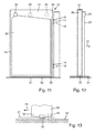
- FIG. 11 schematically shows a pivot 10 with a gate 12, which is very similar to the pivot 10 of Fig. 1 is constructed. It will therefore only the differences to the pivot 10 of Fig. 1 explained.
- a light curtain 31 is generated by means of a laser scanner 29, which is arranged at the lower end of the carrier 14.
- a laser scanner 50 is arranged on an underside of the door leaf 12 and can be designed, for example, extendable from the bottom of the door leaf 12.
- the laser scanner 50 generates the light curtain 31 which extends parallel to a bottom surface 52 between a bottom of the door leaf 12 and the bottom surface 52.
- the light curtain can be set essentially arbitrarily in its dimensions. In the presentation of the Fig. 11 it can be seen that the light curtain 31 extends from the laser scanner 50 over the entire bottom of the gate 12 and only shortly after the in Fig. 11 left end of the gate 12 ends. In the other direction, the light curtain 31, starting from the laser scanner 50, extends somewhat in the direction of the carrier 14.
- the presentation of the Fig. 12 shows the gate 12 of the Fig. 11 in a side view. It can be seen that the light curtain 31 extends from the laser scanner 52 in and opposite to the direction of movement 24 in order to cover the entire underside of the door leaf 12. In the direction of movement 24, the light curtain 31 extends a distance beyond the front of the door leaf 12, for example, to detect objects lying on the ground surface 52 sufficiently far in front of the front of the door leaf 12 to thereby collide the door leaf 12 with such objects avoid.
- the presentation of the Fig. 13 shows the gate 12 of the Fig. 12 in sections in the area of its underside.
- the laser scanner or sensor 50 which has been extended starting from a dashed position within the door leaf 12 in the direction of the bottom surface 52 in order to generate the light curtain 31.
- the direction of movement 24 is shown pointing to the left.
- the door leaf 12 has extendable sealing strips 54 which in the state of Fig. 13 shown within the gate 12 and therefore are indicated only by dashed lines.
- the sealing strips 54 when the door leaf 12 is stationary, preferably in the fully closed position of the swing gate, be extended from the bottom of the door leaf 12 in the direction of the ground surface. This extended position is in Fig. 13 also indicated by dashed lines.
- the laser scanner 50 is arranged between the two extendable sealing strips 54. When the door leaf 12 is to be moved, the sealing strips 54 must first be lifted off the ground surface 54 and retracted into the door leaf 12. At the same time, the laser scanner 50 can be extended from the bottom of the gate 12 and, before the gate 12 begins to move, the light curtain 31 is generated and monitored.
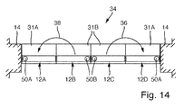
- the presentation of the Fig. 14 shows a pivot according to the invention 34 in the fully closed position.
- the pivot 34 largely corresponds to the in Fig. 5 shown pivot and only the differences to the pivot 34 of Fig. 5 explained.
- the laser scanners 20A, 20B, 20C are made of Fig. 5 for clarity in Fig. 14 are not shown. These laser scanners 20A, 20B, 20C can also be used in the in Fig. 14 illustrated embodiment of the swing gate 34 may be present.
- FIG. 14 Shown in Fig. 14 only four laser scanners 50A, 50B, wherein in each gate leaf 12A, 12B, 12C, 12D each have a laser scanner 50A, 50B is provided.
- Each of the laser scanners 50A, 50B is located between a bottom of the respective door leaf 12A, 12B, 12C, 12D and the bottom surface 52, see Fig. 13 , arranged and can be extendable, for example, from the bottom of the door leaf 12A, 12B, 12C, 12D.
- the laser scanners 50A, 50B each produce a light curtain 31A, 31B.
- the light curtains 31A, 31B are each rectangular in the illustrated embodiment, but may be substantially arbitrarily set with respect to their geometric shape.
- Fig. 14 shows the fully closed state.
- the gate 12B is pivoted in the direction of the curved arrow 38 and the gate 12C is pivoted in the direction of the curved arrow 36.
- the light curtains 31A, 31B between the door leaves 12A, 12B, 12C, 12D therefore cover at the door wings 12B, 12C substantially from the front in the direction of movement area.
- the area in which the door leaf 12B or the door leaf 12C comes to lie is covered.
- the light curtains 31A, 31B respectively cover the complete underside of the door leaves 12A, 12B, 12C, 12D and also extend counter to the direction of movement somewhat beyond the underside of the door leaves 12A, 12B, 12C, 12D.
- the light curtains 31A, 31B may also overlap, as stated, the geometric dimensions of the light curtains 31A, 31B may be set substantially arbitrarily, in order to be adapted to the respective application.
- Fig. 14 Starting from the state of Fig. 14 will, see Fig. 6 , then another intermediate state is reached.
- the respective outer door leaves 12A, 12D are then folded down together with the hinged door leaves 12B and 12C, see Fig. 6, Fig. 7 ,
- the light curtains 31A are then converted for this further movement in such a way that they cover the area of the door leaves 12A, 12D which is then situated in the direction of movement in front. In Fig. 14 this would then be the area below the door leaves 12A, 12D.
Landscapes
- Physics & Mathematics (AREA)
- Life Sciences & Earth Sciences (AREA)
- General Life Sciences & Earth Sciences (AREA)
- General Physics & Mathematics (AREA)
- Geophysics (AREA)
- Power-Operated Mechanisms For Wings (AREA)
Abstract
Die Erfindung betrifft eine Sicherheitsanordnung für Schwenktore mit wenigstens einem Torflügel sowie einem motorischen Antrieb für den Torflügel, bei der wenigstens ein am Torflügel angeordneter Sensor zum Erzeugen und Überwachen eines Lichtvorhangs vorgesehen ist, wobei der Lichtvorhang parallel zu einer in Bewegungsrichtung des Torflügels vorne liegenden Seite des Torflügels angeordnet ist.The invention relates to a safety arrangement for swing gates with at least one gate and a motor drive for the gate, in which at least one arranged on the gate sensor for generating and monitoring a light curtain is provided, wherein the light curtain parallel to a front in the direction of movement of the door leaf side of Door leaf is arranged.
Description
Die Erfindung betrifft eine Sicherheitsanordnung für Schwenktore mit wenigstens einem Torflügel sowie einem motorischen Antrieb für den Torflügel. Die Erfindung betrifft auch einen Torflügel für ein Schwenktor mit einer erfindungsgemäßen Sicherheitsanordnung. Die Erfindung betrifft darüber hinaus ein Verfahren zum Absichern eines Torflügels eines Schwenktores beim Öffnen und Schließen.The invention relates to a safety arrangement for swing gates with at least one gate and a motor drive for the gate. The invention also relates to a gate for a pivot with a safety arrangement according to the invention. The invention further relates to a method for securing a gate of a swing gate when opening and closing.
Mit der Erfindung soll eine verbesserte Absicherung eines Schwenktores mit einem motorischen Antrieb bereitgestellt werden, so dass der motorische Antrieb beim Auftreten von Hindernissen im Bewegungsbereich des Schwenktores rasch abgeschaltet oder reversiert werden kann.With the invention, an improved protection of a swing gate with a motor drive to be provided, so that the motor drive can be switched off or reversed quickly when obstacles occur in the range of motion of the swing gate.
Erfindungsgemäß ist hierzu eine Sicherheitsanordnung für Schwenktore mit den Merkmalen von Anspruch 1, ein Torflügel mit den Merkmalen von Anspruch 10 und ein Verfahren mit den Merkmalen von Anspruch 11 vorgesehen.According to the invention for this purpose a safety arrangement for swing gates with the features of claim 1, a gate with the features of
Erfindungsgemäß ist eine Sicherheitsanordnung für Schwenktore mit wenigstens einem Torflügel sowie einem motorischen Antrieb für den Torflügel vorgesehen, wobei die Sicherheitsanordnung wenigstens einen am Torflügel angeordneten Sensor zum Erzeugen und Überwachen eines Lichtvorhangs aufweist, wobei der Lichtvorhang parallel zu einer in Bewegungsrichtung des Torflügels vorne liegenden Seite des Torflügels und/oder parallel zu einer Bodenoberfläche angeordnet ist.According to the invention, a safety arrangement is provided for swing gates with at least one gate and a motor drive for the gate, wherein the safety arrangement has at least one arranged on the gate sensor for generating and monitoring a light curtain, wherein the light curtain parallel to a front in the direction of movement of the gate leaf side of Gate leaf and / or is arranged parallel to a ground surface.
Überraschenderweise lässt sich durch Vorsehen eines Lichtvorhangs in geringem Abstand vor einer in Bewegungsrichtung des Torflügels vorne liegenden Seite des Torflügels eine zuverlässige Detektion von Hindernissen erreichen. Der Lichtvorhang wird im Abstand von wenigen Zentimetern vor der vorne liegenden Seite des Torflügels eingerichtet. In Bezug auf die Seitenkanten und die Unterkante des Torflügels endet der Lichtvorhang ebenfalls einige wenige Zentimeter vor den Seitenkanten bzw. vor der Unterkante des Torflügels. Beispielsweise hat es sich als vorteilhaft herausgestellt, wenn der Lichtvorhang 2 cm vor der vorne liegenden Seite des Torflügels eingerichtet wird und auch jeweils 2 cm vor den Seitenkanten bzw. der Unterkante des Torflügels endet. Überraschenderweise genügt es dabei, einen Lichtvorhang zum Detektieren von Hindernissen einzusetzen, da moderne Antriebe auch für sehr große Torflügel, insbesondere elektrische Antriebe, sehr rasch gestoppt bzw. reversiert werden können, so dass auch bei einer Detektion von Hindernissen in sehr geringem Abstand vor dem Torflügel, nämlich durch den Lichtvorhang, eine ausreichende Sicherheit gegeben ist. Der Erfindung liegt die Erkenntnis zugrunde, dass ein Lichtvorhang, der an und für sich nur räumlich feststehend zur Absicherung von Gefahrenstellen eingesetzt wird, besonders vorteilhaft und einfach auch zur Absicherung von bewegten Torflügeln von Schwenktüren verwendet werden kann, wenn der Lichtvorhang mit dem Torflügel mitgeführt wird und somit während der Bewegung des Torflügels in geringem Abstand vor der vorne liegenden Seite des Torflügels mit dem Torflügel mitbewegt wird.Surprisingly, by providing a light curtain at a short distance in front of a front in the direction of movement of the door leaf side of the door wing can achieve a reliable detection of obstacles. The light curtain is set up at a distance of a few centimeters in front of the front side of the door leaf. With respect to the side edges and the lower edge of the gate, the light curtain also ends a few centimeters before the side edges or in front of the lower edge of the gate. For example, it has proven to be advantageous if the light curtain is set up 2 cm in front of the front side of the door leaf and also ends in each case 2 cm in front of the side edges or the lower edge of the gate. Surprisingly, it suffices to use a light curtain for detecting obstacles, since modern drives can be very quickly stopped or reversed even for very large gate, in particular electric drives, so that even with a detection of obstacles at a very short distance in front of the gate , namely through the light curtain, adequate security is given. The invention is based on the finding that a light curtain, which is used in and of itself only spatially fixed to secure danger spots, can be used particularly advantageously and simply to secure moving leafs of swing doors when the light curtain is carried along with the door leaf and thus during movement of the door leaf at a small distance in front of the front side of the door leaf is moved with the gate.
Alternativ oder zusätzlich kann der Lichtvorhang auch parallel zur Bodenoberfläche erzeugt werden. Zwischen der Unterseite eines Torflügels und der Bodenoberfläche, über die der Torflügel hinwegbewegt wird, ist in der Regel ausreichend Platz, um einen Sensor zur Erzeugung und Überwachung eines Lichtvorhangs anzuordnen. Der mittels eines solchen Sensors erzeugte Lichtvorhang verläuft dann parallel zur Bodenoberfläche, wobei die Abmessungen des Lichtvorhangs mittels geeigneter Sensoren im Wesentlichen beliebig einstellbar sind. Der Lichtvorhang bewegt sich, wie auch der an der Unterseite des Torflügels angeordnete Sensor, mit dem Torflügel mit, so dass, im Wesentlichen unabhängig von der Stellung des Torflügels, immer ein vordefinierter Bereich in Bewegungsrichtung vor dem Torflügel überwacht werden kann. Wenn vorgesehen ist, den Torflügel im geschlossenen Zustand auch zur Bodenoberfläche hin abzudichten, können ausfahrbare Dichtungsleisten an der Unterseite des Torflügels vorgesehen sein. Bevor sich der Torflügel beginnt zu bewegen, müssen die Dichtleisten ohnehin wieder von der Bodenoberfläche abgehoben werden, so dass dann mittels der Sensoren der Lichtvorhang erzeugt und die Bewegung des Torflügels abgesichert werden kann.Alternatively or additionally, the light curtain can also be generated parallel to the ground surface. Between the bottom of a gate and the ground surface, over which the gate is moved away, is usually enough space to arrange a sensor for generating and monitoring a light curtain. The light curtain generated by means of such a sensor then runs parallel to the ground surface, wherein the dimensions of the light curtain can be adjusted substantially arbitrarily by means of suitable sensors. The light curtain moves, as well as arranged on the underside of the gate sensor with the gate, so that, regardless of the position of the gate, always a predefined area in the direction of movement can be monitored in front of the gate. If it is provided to seal the door leaf in the closed state also to the bottom surface, extendable sealing strips can be provided on the underside of the gate leaf. Before the door leaf begins to move, the sealing strips have to be lifted off the floor surface anyway, so that the light curtain can then be generated by means of the sensors and the movement of the door leaf can be ensured.
In Weiterbildung der Erfindung ist der Sensor als Laserscanner ausgebildet.In a further development of the invention, the sensor is designed as a laser scanner.
Gerade Laserscanner haben sich als besonders vorteilhaft für die Absicherung von Schwenktoren erwiesen. Ein Laserstrahl oder mehrere Laserstrahlen werden dabei in einer Ebene abgelenkt, um einen Lichtvorhang aufzuspannen.Especially laser scanners have proven to be particularly advantageous for securing swing gates. One or more laser beams are deflected in a plane to open a light curtain.
In Weiterbildung der Erfindung ist der Sensor als Infrarot-Laserscanner ausgebildet.In a further development of the invention, the sensor is designed as an infrared laser scanner.
Auf diese Weise kann ein für das menschliche Auge unsichtbarer Lichtvorhang bereitgestellt werden.In this way, an invisible to the human eye light curtain can be provided.
In Weiterbildung der Erfindung ist ein Erfassungsbereich des Sensors in zwei Richtungen parallel zur Vorderseite des Torflügels einstellbar.In a development of the invention, a detection range of the sensor is adjustable in two directions parallel to the front side of the door leaf.
Auf diese Weise kann der Lichtvorhang seitlich, nach oben und nach unten begrenzt werden und dadurch genau die Vorderseite des Torflügels bzw. einen gewünschten Abschnitt der Vorderseite des Torflügels absichern. Eine solche Einstellung des Erfassungsbereichs des Sensors erfolgt bei einem Laserscanner beispielsweise dadurch, dass der Laserscanner mit einer Laufzeitmessung des Lichts arbeitet und zum Einstellen des Erfassungsbereichs je nach Ablenkungswinkel des Laserstrahls die zu erwartende Lichtlaufzeit eingestellt wird.In this way, the light curtain can be limited laterally, upwards and downwards and thereby ensure exactly the front of the door leaf or a desired portion of the front of the door leaf. Such a setting of the detection range of the sensor is carried out in a laser scanner, for example, by the fact that the laser scanner operates with a transit time measurement of the light and to set the detection range depending on the deflection angle of the laser beam, the expected light transit time is set.
In Weiterbildung der Erfindung ist ein Erfassungsbereich des Sensors in Abhängigkeit eines Öffnungswinkels des Torflügels einstellbar.In a development of the invention, a detection range of the sensor can be set as a function of an opening angle of the door leaf.
Auf diese Weise lassen sich beim Öffnen oder Schließen eines Torflügels eines Schwenktores ändernde geometrische Verhältnisse berücksichtigen. Beispielsweise wird ein Spalt zwischen zwei Torflügeln eines doppelflügeligen Schwenktores beim Aneinanderklappen der beiden Flügel irgendwann so eng, dass keine menschlichen Gliedmaßen mehr in den Spalt hineinpassen. Darüber hinaus muss eine Erfassung von Hindernissen zwangsläufig abgestellt werden, um die beiden Torflügel überhaupt aneinander anklappen zu können. Durch Änderung des Erfassungsbereichs des Sensors in Abhängigkeit vom Schwenkwinkel lassen sich beim Öffnen oder Schließen verändernde räumliche Verhältnisse berücksichtigen. Besonders vorteilhaft ist dabei, dass der Erfassungsbereich des Sensors in einfacher Weise programmierbar ist und der Sensor dadurch leicht auf geänderte räumliche Verhältnisse abgestimmt werden kann.In this way, can be considered when opening or closing a gate of a swing gate changing geometric relationships. For example, a gap between two leaves of a double-wing swing gate when folding the two wings at some point so tight that no human limbs fit more in the gap. In addition, a detection of obstacles must be turned off inevitably in order to fold the two wings at all. By changing the detection range of the sensor as a function of the swivel angle, changing spatial conditions can be taken into account when opening or closing. It is particularly advantageous that the detection range of the sensor is programmable in a simple manner and the sensor can be easily adapted to changing spatial conditions.
In Weiterbildung der Erfindung ragt der Sensor im Betrieb aus der vorne liegenden Seite des Torflügels vor.In a further development of the invention, the sensor protrudes during operation from the front side of the door leaf.
Auf diese Weise kann der Lichtvorhang zuverlässig in geringem Abstand und parallel zur vorne liegenden Seite des Torflügels aufgespannt werden.In this way, the light curtain can be reliably clamped at a small distance and parallel to the front side of the door leaf.
In Weiterbildung der Erfindung ist wenigstens ein Aktuator vorgesehen, um den Sensor ausgehend von einer bündig oder innerhalb des Torflügels angeordneten Ruhestellung in eine aus der vorne liegenden Seite des Torflügels vorragende Betriebsstellung zu bewegen.In a further development of the invention, at least one actuator is provided in order to move the sensor, starting from a rest position arranged flush or within the door leaf, into an operating position protruding from the front side of the door leaf.
Aus Designgründen kann vorgesehen sein, dass erst kurz vor Beginn der Bewegung des Torflügels der Sensor aus der Oberfläche des Torflügels herausgefahren wird und dann den Lichtvorhang aufspannt. Beispielsweise können beim Öffnen eines Torflügels nur die Sensoren in der Vorderseite des Torflügels ausgefahren werden, beim Schließen des Torflügels werden dann lediglich die an der hinten liegenden Seite des Torflügels angeordneten Sensoren ausgefahren. Beim vollständigen, parallelen Anlegen eines Torflügels an eine Wand eines Gebäudes oder einen anderen Torflügel können die Sensoren dann rechtzeitig wieder in das Innere des Torflügels eingefahren werden.For design reasons, it may be provided that the sensor is moved out of the surface of the door leaf only shortly before the movement of the door leaf, and then tenses the light curtain. For example, when opening a gate only the sensors in the front of the gate are extended, when closing the gate then only arranged on the rear side of the gate sensors are extended. For the complete, parallel application of a door leaf to a wall of a building or another gate, the sensors can then be retracted back into the interior of the gate in good time.
In Weiterbildung der Erfindung sind wenigstens an den Seitenkanten des Torflügels Schaltleisten vorgesehen, die beim Annähern an ein Hindernis oder beim Berühren eines Hindernisses ein Schaltsignal erzeugen.In a further development of the invention, safety edges are provided at least on the side edges of the gate, which generate a switching signal when approaching an obstacle or when touching an obstacle.
Solche Schaltleisten oder Sicherheitskontaktleisten sind für die Sicherheit an Quetschstellen und Scherstellen vorteilhaft. Beispielsweise dann wenn sehr dicke Türflügel um 180° ausgeklappt werden, tritt zwischen den Schmalseiten der Türflügel ein sich allmählich verringernder Spalt auf, der gegen das Einklemmen von menschlichen Gliedmaßen abgesichert werden muss. Weitere Sensoren, beispielsweise optische Sensoren, können ebenfalls eingesetzt werden, um beispielsweise tote Winkel abzusichern. Beispielsweise können zusätzliche Lichtvorhänge parallel zur Bodenoberfläche eingesetzt werden, um sicherzustellen, dass keine Person im Bereich des Tores am Boden liegt oder steht. Sensoren für solche Lichtvorhänge sind vorteilhafterweise an dem Träger angeordnet. Es kann sinnvoll sein, solche Lichtvorhänge, die parallel zur Bodenoberfläche verlaufen, nur zeitweise während des Öffnens oder Schließens zu aktivieren, beispielsweise kurz vor dem endgültigen Schließen des Tors.Such safety edges or safety contact strips are advantageous for the safety of pinch points and shearing points. For example, when very thick door leaves are folded out by 180 °, occurs between the narrow sides of the door a gradually decreasing gap, which must be secured against the pinching of human limbs. Other sensors, such as optical sensors, can also be used to protect, for example, blind spots. For example, additional light curtains can be used parallel to the floor surface to ensure that no person lies or stands on the floor near the door. Sensors for such light curtains are advantageously arranged on the carrier. It may be useful to activate such light curtains that run parallel to the ground surface, only temporarily during opening or closing, for example, just before the final closing of the gate.
In Weiterbildung der Erfindung ragt der Sensor im Betrieb aus der Unterseite des Torflügels vor.In development of the invention, the sensor protrudes in operation from the bottom of the gate.
Auf diese Weise kann ein im Zwischenraum zwischen der Unterseite des Torflügels und der Bodenoberfläche angeordneter Lichtvorhang erzeugt werden, der dann parallel zur Bodenoberfläche verläuft. Es kann vorgesehen sein, dass der Sensor vor dem Erzeugen des Lichtvorhangs aus der Unterseite des Torflügels ausfährt. Beispielsweise kann der Sensor zwischen ausfahrbaren Dichtleisten an der Vorderkante und der Hinterkante des Torflügels angeordnet sein. Die Dichtleisten sind lediglich bei Stillstand des Tors im geschlossenen Zustand so weit ausgefahren, dass sie auf der Bodenoberfläche aufliegen. Bevor der Torflügel beginnt, sich zu bewegen, werden die Dichtleisten von der Bodenoberfläche abgehoben und der zwischen den Dichtleisten angeordnete Sensor kann den Lichtvorhang erzeugen.In this way, a arranged in the space between the bottom of the gate and the bottom surface light curtain can be generated, which then runs parallel to the ground surface. It may be provided that the sensor extends from the underside of the door leaf before generating the light curtain. For example, the sensor can be arranged between extendable sealing strips on the front edge and the rear edge of the door leaf. The sealing strips are extended so far only when the door is in the closed state that they rest on the ground surface. Before the door leaf begins to move, the sealing strips are lifted off the floor surface and the sensor arranged between the sealing strips can generate the light curtain.
Die Erfindung betrifft auch einen Torflügel für ein Schwenktor mit einer erfindungsgemäßen Sicherheitsanordnung.The invention also relates to a gate for a pivot with a safety arrangement according to the invention.
Die Erfindung betrifft auch ein Schwenktor mit wenigstens zwei Torflügeln mit einer erfindungsgemäßen Sicherheitsanordnung, wobei ein erster Torflügel mit einer ersten Schmalseite schwenkbar an einem feststehenden Träger angeordnet ist, wobei ein zweiter Torflügel schwenkbar an einer zweiten Schmalseite des ersten Torflügels angeordnet ist und wobei wenigstens ein motorischer Antrieb zum Verschwenken des ersten und des zweiten Torflügels vorgesehen ist, bei dem der erste Torflügel wenigstens auf seiner beim Öffnen in Bewegungsrichtung vorne liegenden Seite mit einem ersten Sensor versehen ist, bei dem der zweite Torflügel auf seiner beim Öffnen in Bewegungsrichtung vorne liegenden Seite mit einem zweiten Sensor versehen ist und bei dem der zweite Torflügel auf seiner beim Öffnen in Bewegungsrichtung hinten liegenden Seite mit einem dritten Sensor versehen ist.The invention also relates to a pivot with at least two leafs with a safety arrangement according to the invention, wherein a first leaf with a first narrow side is pivotally mounted on a fixed support, wherein a second leaf is arranged pivotably on a second narrow side of the first door leaf and wherein at least one motor drive for pivoting the first and the second door leaf is provided, wherein the first door leaf is provided at least on its front opening in the direction of movement with a first sensor at the second gate is provided on its front side in the direction of movement in the direction of movement with a second sensor and in which the second gate is provided on its rear side in the direction of movement with a third sensor.
Für ein solches mehrflügeliges Schwenktor, bei dem ein erster Torflügel ausgehend vom geschlossenen ebenen Zustand des Schwenktores um 180° geklappt und parallel zum ersten Torflügel angeordnet wird und dann das Flügelpaket aus den beiden parallel zueinander angeordneten Torflügeln gemeinsam um 90° verschwenkt wird, sind somit mindestens drei Sensoren vorgesehen, um eine Bewegung der Torflügel des Schwenktores gegen eventuell auftretende Hindernisse beim Öffnen und Schließen abzusichern. Der erste, mit einem feststehenden Träger verbundene Torflügel benötigt dabei lediglich einen Sensor, da dieser erste Torflügel lediglich beim Öffnen des Schwenktores in Bewegungsrichtung vorne liegt. Beim Schließen des Schwenktores wird dieser erste Torflügel zwar auch ausgeklappt, in Bewegungsrichtung vorne liegt aber der zweite Torflügel, der in der vollständig geöffneten Stellung ja parallel an den ersten Torflügel angeklappt ist. Der zweite Torflügel benötigt bei einer solchen Schwenktoranordnung auf seiner Vorderseite und seiner Rückseite jeweils einen Sensor, der einen Lichtvorhang aufspannt, um die Bewegung des zweiten Torflügels sowohl beim Öffnen als auch beim Schließen abzusichern.For such a multi-leaf pivot, in which a first door leaf, starting from the closed flat state of the swing gate folded by 180 ° and is arranged parallel to the first door leaf and then the wing assembly of the two mutually parallel gate leaves is pivoted together by 90 °, are thus at least three sensors provided to hedge a movement of the swing gate sash against any obstacles during opening and closing. The first, connected to a fixed support door leaf only needs a sensor, since this first door leaf is located only when opening the swing gate in the direction of movement forward. When closing the swing gate, this first door wing is also folded out, but in the direction of movement forward is the second door leaf, which is indeed folded in the fully open position parallel to the first door leaf. The second gate requires in such a pivot assembly on its front and its back each have a sensor that spans a light curtain to secure the movement of the second gate both when opening and closing.
Bei einem erfindungsgemäßen Verfahren zum Absichern eines Torflügels eines Schwenktores beim Öffnen und Schließen wird ein Lichtvorhang parallel zu einer in Bewegungsrichtung vorne liegenden Seite des Torflügels und/oder parallel zu einer Bodenoberfläche erzeugt und eine Bewegung des Torflügels wird beim Detektieren eines Hindernisses im Bereich des Lichtvorhangs angehalten und/oder reversiert. Der Lichtvorhang beziehungsweise mehrere Lichtvorhänge werden vorteilhafterweise mittels eines Laserscanners erzeugt.In a method according to the invention for securing a door leaf of a swing gate during opening and closing, a light curtain is generated parallel to a front side of the door leaf in the direction of movement and / or parallel to a ground surface, and a movement of the door leaf is stopped when detecting an obstacle in the area of the light curtain and / or reversed. The light curtain or several light curtains are advantageously generated by means of a laser scanner.
In Weiterbildung der Erfindung wird der Lichtvorhang mit dem Torflügel beim Öffnen und Schließen mitbewegt.In a further development of the invention, the light curtain is moved with the gate during opening and closing.
Vorteilhafterweise sind die Sensoren zum Erzeugen und Überwachen des Lichtvorhangs im Torflügel selbst angeordnet. Dadurch wird der Lichtvorhang zwangsläufig beim Öffnen und Schließen des Torflügels mitbewegt. Der Lichtvorhang ist dadurch automatisch immer dort angeordnet, wo er auch benötigt wird, nämlich in Bewegungsrichtung vor dem Torflügel.Advantageously, the sensors for generating and monitoring the light curtain are arranged in the gate itself. As a result, the light curtain is inevitably moved when opening and closing the door leaf. The light curtain is thus always automatically located where it is needed, namely in the direction of movement in front of the gate.
In Weiterbildung der Erfindung ist das Ausfahren von Sensoren zum Erzeugen und Überwachen des Lichtvorhangs vor einem Beginn der Bewegung des Torflügels beim Öffnen und Schließen vorgesehen.In a further development of the invention, the extension of sensors for generating and monitoring the light curtain is provided before a start of the movement of the gate during opening and closing.
Auf diese Weise können die Sensoren gegen Verschmutzung und Beschädigung geschützt angeordnet sein, wenn sich das Tor nicht bewegt. Lediglich dann, wenn die Sensoren zum Erzeugen und Überwachen des Lichtvorhangs benötigt werden, werden sie aus einer geschützten Ruhestellung in eine ausgefahrene Arbeitsstellung bewegt. Weitere Merkmale und Vorteile der Erfindung ergeben sich aus den Ansprüchen und der Beschreibung bevorzugter Ausführungsformen der Erfindung im Zusammenhang mit den beigefügten Zeichnungen. In den einzelnen Zeichnungen dargestellte Einzelmerkmale der unterschiedlichen Ausführungsformen lassen sich dabei in beliebiger Weise kombinieren, ohne den Rahmen der Erfindung zu überschreiten. In den Zeichnungen zeigen:
- Fig. 1
- eine schematische Vorderansicht eines Torflügels eines Schwenktores mit einer erfindungsgemäßen Sicherheitsanordnung,
- Fig. 2
- eine Seitenansicht des Torflügels der
Fig. 1 , - Fig. 3
- eine schematische abschnittsweise Seitenansicht des Torflügels der
Fig. 3 bei eingefahrenem Sensor, - Fig. 4
- eine
Fig. 3 entsprechende Darstellung des Torflügels bei ausgefahrenem Sensor, - Fig. 5, 6 und 7
- verschiedene Zwischenstellungen beim Öffnen eines erfindungsgemäßen Schwenktores;
- Fig. 8, 9
und 10 - verschiedene Zwischenstellungen beim Schließen eines erfindungsgemäßen Schwenktores,
- Fig. 11
- eine schematische Vorderansicht eines Torflügels eines Schwenktors mit einer erfindungsgemäßen Sicherheitsanordnung gemäß einer weiteren Ausführungsform der Erfindung,
- Fig. 12
- eine Seitenansicht des Torflügels der
Fig. 1 , - Fig. 13
- eine abschnittsweise Ansicht des Torflügels der
Fig. 12 und - Fig. 14
- eine schematische Darstellung eines erfindungsgemäßen Schwenktors von oben in der vollständig geschlossenen Stellung.
- Fig. 1
- a schematic front view of a gate of a swing gate with a safety arrangement according to the invention,
- Fig. 2
- a side view of the gate of the
Fig. 1 . - Fig. 3
- a schematic sectional side view of the gate of the
Fig. 3 with retracted sensor, - Fig. 4
- a
Fig. 3 corresponding representation of the door leaf with the sensor extended, - FIGS. 5, 6 and 7
- various intermediate positions when opening a swing gate according to the invention;
- FIGS. 8, 9 and 10
- different intermediate positions when closing a swing gate according to the invention,
- Fig. 11
- 1 is a schematic front view of a door leaf of a swing gate with a safety arrangement according to the invention according to a further embodiment of the invention,
- Fig. 12
- a side view of the gate of the
Fig. 1 . - Fig. 13
- a sectional view of the gate of the
Fig. 12 and - Fig. 14
- a schematic representation of a pivoting gate according to the invention from above in the fully closed position.
Die Darstellung der
Der Torflügel 12 ist mit wenigstens einem Laserscanner 20 versehen, der einen Lichtvorhang 22 aufspannt. Der Lichtvorhang 22 ist, siehe auch
Der Lichtvorhang 22 deckt einen Bereich unterhalb des Laserscanners 20 ab. Der Torflügel 12 ist im dargestellten Beispiel sehr hoch und weist eine Höhe von etwa 2 bis 3 m auf. Es genügt daher, wenn der Laserscanner 20 einen Bereich unterhalb des Laserscanners 20 auf Hindernisse überwacht. Der Lichtvorhang 22 endet dabei jeweils wenige Zentimeter, insbesondere 2 cm, vor den Seitenkanten des Torflügels 12. Der Lichtvorhang 22 endet ebenfalls wenige Zentimeter, insbesondere 2 cm, vor einer Unterkante des Torflügels 12. Dadurch, dass der Lichtvorhang wenige Zentimeter vor einer Unterkante des Torflügels 12 endet, wird ermöglicht, dass sehr flache Hindernisse, die niedriger sind als ein menschlicher Fuß, nicht zu einem Abstoppen des Torflügels 12 führen und dadurch beispielsweise kleine Steine oder flache Gegenstände beim Öffnen des Torflügels 12 weggeschoben werden können.The
Um je nach den gegebenen räumlichen Verhältnissen aber beispielsweise auch das Einklemmen von menschlichen Gliedmaßen oder Gegenständen unterhalb einer Unterkante des Torflügels 12 zu verhindern, kann eine Unterkante des Torflügels 12 darüber hinaus mit einer Sicherheitskontaktleiste versehen sein.In order to prevent depending on the given spatial conditions but also, for example, the pinching of human limbs or objects below a lower edge of the
Bei der dargestellten Ausführungsform sind die in
In der Darstellung der
Ein weiterer Laserscanner 29 ist am Träger 14 vorgesehen, und zwar am unteren Ende des Trägers, wo dieser in die Bodenoberfläche übergeht. Dieser Laserscanner 29 spannt einen Lichtvorhang 31 auf, der parallel zur Bodenoberfläche verläuft und sich unterhalb des Torflügels 12 erstreckt. Ein solcher Lichtvorhang 31 dient zur Abdeckung von toten Winkeln, insbesondere kurz vor dem vollständigen Schließen des Torflügels 12. Mittels des Lichtvorhangs 31, siehe auch
Wie
Der Laserscanner 20 kann dabei in seiner in
Die Darstellung der
Die Darstellung der
Die Torflügel 12b, 12c werden als zweite Torflügel bezeichnet und sind schwenkbar mit einer Schmalseite der ersten Torflügel 12a, 12d verbunden, wobei diese Schmalseite den Trägern 14 abgewandt ist.The leafs 12b, 12c are referred to as second leaf and are pivotally connected to a narrow side of the first leaf 12a, 12d, said narrow side facing away from the
Die ersten Torflügel 12a, 12d sind jeweils mit einem ersten Laserscanner 20a versehen, der in der Darstellung der
Die zweiten Torflügel 12b, 12c sind jeweils noch mit einem dritten Laserscanner 20c versehen, der auf der beim Öffnen hinten liegenden Seite der zweiten Torflügel 12b, 12c angeordnet ist. Die dritten Laserscanner 20c sind in der Darstellung der
Zum Öffnen des Schwenktores 34 werden zunächst die zweiten Torflügel 12b, 12c um 180° nach außen, also zu den Trägern 14 hin geklappt. Diese Klappbewegung ist durch die gebogenen Pfeile 36, 38 in
Ausgehend vom Zustand der
Ausgehend von der Stellung der
Ausgehend von der Stellung der
Genauso sind die beiden Torflügel 12d und 12c nun parallel zu dem in
Die Darstellungen der
In gleicher Weise wird der dritte Laserscanner 20c in dem zweiten Torflügel 12c ausgefahren, spannt einen Lichtvorhang auf und nachfolgend wird das Paket aus den Torflügeln 12c, 12d gemeinsam um 90° vom in
Ausgehend vom Zustand der
Ausgehend vom Zustand der
Anhand der
In
Im Ergebnis lässt sich durch die erfindungsgemäße Sicherheitsanordnung und das erfindungsgemäße Schwenktor 34 eine sehr zuverlässige Absicherung der Bewegung eines motorisch betriebenen Schwenktores mit geringem Aufwand zuverlässig realisieren.As a result, a very reliable protection of the movement of a motor-driven swing gate with little effort can be reliably realized by the safety arrangement according to the invention and the
Die Darstellung der
Beim Schwenktor 10 der
Die Darstellung der
Die Darstellung der
Der Torflügel 12 weist ausfahrbare Dichtleisten 54 auf, die im Zustand der
Die Darstellung der
Dargestellt sind in
Der Zustand der
Es ist zu erkennen, dass die Lichtvorhänge 31A, 31 B jeweils die vollständige Unterseite der Torflügel 12A, 12B, 12C, 12D abdecken und sich auch entgegen der Bewegungsrichtung ein Stück weit über die Unterseite der Torflügel 12A, 12B, 12C, 12D hinaus erstrecken. Die Lichtvorhänge 31A, 31 B können sich auch überlappen, wie ausgeführt können die geometrischen Abmessungen der Lichtvorhänge 31A, 31 B im Wesentlichen beliebig eingestellt werden, um auf den jeweils vorliegenden Anwendungsfall angepasst zu werden.It can be seen that the
Ausgehend vom Zustand der
Die Anordnung der Laserscanner bzw. Sensoren 50A, 50B an einer Unterseite der Torflügel 12A, 12B, 12C, 12D, insbesondere ausfahrbar aus der jeweiligen Unterseite, ermöglicht es, eine gegen Verschmutzung und Beschädigung sehr unempfindliche Anordnung zu schaffen.The arrangement of the laser scanner or
Claims (14)
Applications Claiming Priority (2)
| Application Number | Priority Date | Filing Date | Title |
|---|---|---|---|
| DE102014221953.1A DE102014221953A1 (en) | 2014-10-28 | 2014-10-28 | Safety arrangement for swing gates, gate and swing and method for securing a gate of a swing gate |
| DE102015200518.6A DE102015200518A1 (en) | 2015-01-15 | 2015-01-15 | Safety arrangement for swing gates, gate and swing and method for securing a gate of a swing gate |
Publications (2)
| Publication Number | Publication Date |
|---|---|
| EP3015631A1 true EP3015631A1 (en) | 2016-05-04 |
| EP3015631B1 EP3015631B1 (en) | 2019-09-04 |
Family
ID=54478557
Family Applications (1)
| Application Number | Title | Priority Date | Filing Date |
|---|---|---|---|
| EP15191386.0A Active EP3015631B1 (en) | 2014-10-28 | 2015-10-26 | Gate wing with safety assembly and method for securing a gate wing of a pivoting gate |
Country Status (4)
| Country | Link |
|---|---|
| EP (1) | EP3015631B1 (en) |
| DK (1) | DK3015631T3 (en) |
| ES (1) | ES2758510T3 (en) |
| HU (1) | HUE046726T2 (en) |
Citations (5)
| Publication number | Priority date | Publication date | Assignee | Title |
|---|---|---|---|---|
| DE10129230C1 (en) * | 2001-06-19 | 2002-06-20 | Dorma Gmbh & Co Kg | Sensor arrangement for room area involves transmitters and receivers, and auxiliary transmitters and receivers, in modules, in casting compound |
| US20040233414A1 (en) * | 2003-05-19 | 2004-11-25 | Jamieson James R. | Laser perimeter awareness system |
| EP1832866A2 (en) * | 2004-07-22 | 2007-09-12 | Bea S.A. | A door sensor system for detecting a target object |
| EP2108775A2 (en) * | 2008-04-11 | 2009-10-14 | GEZE GmbH | Automatic door system |
| EP2226452A1 (en) * | 2008-12-12 | 2010-09-08 | Pepperl + Fuchs GmbH | Door monitoring sensor |
Family Cites Families (1)
| Publication number | Priority date | Publication date | Assignee | Title |
|---|---|---|---|---|
| EP2648022B1 (en) * | 2012-04-02 | 2017-03-08 | Cedes AG | Monitoring device and pivoting door |
-
2015
- 2015-10-26 EP EP15191386.0A patent/EP3015631B1/en active Active
- 2015-10-26 HU HUE15191386A patent/HUE046726T2/en unknown
- 2015-10-26 ES ES15191386T patent/ES2758510T3/en active Active
- 2015-10-26 DK DK15191386T patent/DK3015631T3/en active
Patent Citations (5)
| Publication number | Priority date | Publication date | Assignee | Title |
|---|---|---|---|---|
| DE10129230C1 (en) * | 2001-06-19 | 2002-06-20 | Dorma Gmbh & Co Kg | Sensor arrangement for room area involves transmitters and receivers, and auxiliary transmitters and receivers, in modules, in casting compound |
| US20040233414A1 (en) * | 2003-05-19 | 2004-11-25 | Jamieson James R. | Laser perimeter awareness system |
| EP1832866A2 (en) * | 2004-07-22 | 2007-09-12 | Bea S.A. | A door sensor system for detecting a target object |
| EP2108775A2 (en) * | 2008-04-11 | 2009-10-14 | GEZE GmbH | Automatic door system |
| EP2226452A1 (en) * | 2008-12-12 | 2010-09-08 | Pepperl + Fuchs GmbH | Door monitoring sensor |
Also Published As
| Publication number | Publication date |
|---|---|
| ES2758510T3 (en) | 2020-05-05 |
| HUE046726T2 (en) | 2020-03-30 |
| EP3015631B1 (en) | 2019-09-04 |
| DK3015631T3 (en) | 2019-12-09 |
Similar Documents
| Publication | Publication Date | Title |
|---|---|---|
| DE102008044990B4 (en) | Method and device for controlling and / or monitoring a motor-driven wing during the opening phase | |
| EP3247860B1 (en) | Method of controlling a door arrangement, a such door arrangement and a safety arrangement therefor | |
| EP3584400B1 (en) | Safety door and method for operating a safety door | |
| EP0232866B1 (en) | Opening and/or closing control device for fast-moving doors | |
| EP2802500A1 (en) | Platform door system, method for operating a platform door system and door frame for a platform door system | |
| WO2008135058A1 (en) | Device for exhibiting objects | |
| DE10228930B4 (en) | Sensor device for an automatic revolving door system | |
| DE202010007645U1 (en) | Protection device for the protection of automatically operating systems | |
| DE19653026B4 (en) | Device for controlling and / or securing a motor-driven wing of a door, a window or the like | |
| DE3344576C1 (en) | Sensor arrangement for monitoring the pivoting range of door wings | |
| DE102015200518A1 (en) | Safety arrangement for swing gates, gate and swing and method for securing a gate of a swing gate | |
| DE10064702C2 (en) | Openable vehicle roof and method for operating the same | |
| DE102014221953A1 (en) | Safety arrangement for swing gates, gate and swing and method for securing a gate of a swing gate | |
| DE102013212518B4 (en) | Automatic window or door system | |
| DE3416546A1 (en) | Safety device for stopping motor-driven objects | |
| EP0379465B1 (en) | Fibre bale opener with a safety device | |
| DE60203946T2 (en) | Ankle protection device for automatic doors, in particular for lifts | |
| EP3015631B1 (en) | Gate wing with safety assembly and method for securing a gate wing of a pivoting gate | |
| DE102015002350A1 (en) | Anti-jamming device for a vehicle door or vehicle flap, which can be pivoted by a motor about a hinge axis | |
| EP2248980B1 (en) | Sliding / folding shutter | |
| DE202005016087U1 (en) | Building or yard completion device | |
| WO2001053644A1 (en) | Sectional lifting or collapsible door | |
| EP0852313A1 (en) | Device for controlling and/or securing motor-driven door panels, windows or the like | |
| DE19804573C1 (en) | Method and device for controlling and / or monitoring a motor-driven wing | |
| DE102004053820B4 (en) | Sensor arrangement for automatic door systems |
Legal Events
| Date | Code | Title | Description |
|---|---|---|---|
| PUAI | Public reference made under article 153(3) epc to a published international application that has entered the european phase |
Free format text: ORIGINAL CODE: 0009012 |
|
| AK | Designated contracting states |
Kind code of ref document: A1 Designated state(s): AL AT BE BG CH CY CZ DE DK EE ES FI FR GB GR HR HU IE IS IT LI LT LU LV MC MK MT NL NO PL PT RO RS SE SI SK SM TR |
|
| AX | Request for extension of the european patent |
Extension state: BA ME |
|
| STAA | Information on the status of an ep patent application or granted ep patent |
Free format text: STATUS: REQUEST FOR EXAMINATION WAS MADE |
|
| 17P | Request for examination filed |
Effective date: 20161104 |
|
| RBV | Designated contracting states (corrected) |
Designated state(s): AL AT BE BG CH CY CZ DE DK EE ES FI FR GB GR HR HU IE IS IT LI LT LU LV MC MK MT NL NO PL PT RO RS SE SI SK SM TR |
|
| STAA | Information on the status of an ep patent application or granted ep patent |
Free format text: STATUS: EXAMINATION IS IN PROGRESS |
|
| 17Q | First examination report despatched |
Effective date: 20170614 |
|
| GRAP | Despatch of communication of intention to grant a patent |
Free format text: ORIGINAL CODE: EPIDOSNIGR1 |
|
| STAA | Information on the status of an ep patent application or granted ep patent |
Free format text: STATUS: GRANT OF PATENT IS INTENDED |
|
| INTG | Intention to grant announced |
Effective date: 20190314 |
|
| GRAS | Grant fee paid |
Free format text: ORIGINAL CODE: EPIDOSNIGR3 |
|
| GRAA | (expected) grant |
Free format text: ORIGINAL CODE: 0009210 |
|
| STAA | Information on the status of an ep patent application or granted ep patent |
Free format text: STATUS: THE PATENT HAS BEEN GRANTED |
|
| AK | Designated contracting states |
Kind code of ref document: B1 Designated state(s): AL AT BE BG CH CY CZ DE DK EE ES FI FR GB GR HR HU IE IS IT LI LT LU LV MC MK MT NL NO PL PT RO RS SE SI SK SM TR |
|
| REG | Reference to a national code |
Ref country code: GB Ref legal event code: FG4D Free format text: NOT ENGLISH |
|
| REG | Reference to a national code |
Ref country code: CH Ref legal event code: EP |
|
| REG | Reference to a national code |
Ref country code: AT Ref legal event code: REF Ref document number: 1175573 Country of ref document: AT Kind code of ref document: T Effective date: 20190915 |
|
| REG | Reference to a national code |
Ref country code: DE Ref legal event code: R096 Ref document number: 502015010226 Country of ref document: DE |
|
| REG | Reference to a national code |
Ref country code: IE Ref legal event code: FG4D Free format text: LANGUAGE OF EP DOCUMENT: GERMAN |
|
| REG | Reference to a national code |
Ref country code: RO Ref legal event code: EPE |
|
| REG | Reference to a national code |
Ref country code: DK Ref legal event code: T3 Effective date: 20191204 |
|
| REG | Reference to a national code |
Ref country code: CH Ref legal event code: NV Representative=s name: DR. LUSUARDI AG, CH |
|
| REG | Reference to a national code |
Ref country code: NL Ref legal event code: MP Effective date: 20190904 |
|
| REG | Reference to a national code |
Ref country code: LT Ref legal event code: MG4D Ref country code: NO Ref legal event code: T2 Effective date: 20190904 |
|
| PG25 | Lapsed in a contracting state [announced via postgrant information from national office to epo] |
Ref country code: BG Free format text: LAPSE BECAUSE OF FAILURE TO SUBMIT A TRANSLATION OF THE DESCRIPTION OR TO PAY THE FEE WITHIN THE PRESCRIBED TIME-LIMIT Effective date: 20191204 Ref country code: SE Free format text: LAPSE BECAUSE OF FAILURE TO SUBMIT A TRANSLATION OF THE DESCRIPTION OR TO PAY THE FEE WITHIN THE PRESCRIBED TIME-LIMIT Effective date: 20190904 Ref country code: HR Free format text: LAPSE BECAUSE OF FAILURE TO SUBMIT A TRANSLATION OF THE DESCRIPTION OR TO PAY THE FEE WITHIN THE PRESCRIBED TIME-LIMIT Effective date: 20190904 Ref country code: LT Free format text: LAPSE BECAUSE OF FAILURE TO SUBMIT A TRANSLATION OF THE DESCRIPTION OR TO PAY THE FEE WITHIN THE PRESCRIBED TIME-LIMIT Effective date: 20190904 Ref country code: FI Free format text: LAPSE BECAUSE OF FAILURE TO SUBMIT A TRANSLATION OF THE DESCRIPTION OR TO PAY THE FEE WITHIN THE PRESCRIBED TIME-LIMIT Effective date: 20190904 |
|
| PG25 | Lapsed in a contracting state [announced via postgrant information from national office to epo] |
Ref country code: AL Free format text: LAPSE BECAUSE OF FAILURE TO SUBMIT A TRANSLATION OF THE DESCRIPTION OR TO PAY THE FEE WITHIN THE PRESCRIBED TIME-LIMIT Effective date: 20190904 Ref country code: RS Free format text: LAPSE BECAUSE OF FAILURE TO SUBMIT A TRANSLATION OF THE DESCRIPTION OR TO PAY THE FEE WITHIN THE PRESCRIBED TIME-LIMIT Effective date: 20190904 Ref country code: LV Free format text: LAPSE BECAUSE OF FAILURE TO SUBMIT A TRANSLATION OF THE DESCRIPTION OR TO PAY THE FEE WITHIN THE PRESCRIBED TIME-LIMIT Effective date: 20190904 Ref country code: GR Free format text: LAPSE BECAUSE OF FAILURE TO SUBMIT A TRANSLATION OF THE DESCRIPTION OR TO PAY THE FEE WITHIN THE PRESCRIBED TIME-LIMIT Effective date: 20191205 |
|
| REG | Reference to a national code |
Ref country code: HU Ref legal event code: AG4A Ref document number: E046726 Country of ref document: HU |
|
| PG25 | Lapsed in a contracting state [announced via postgrant information from national office to epo] |
Ref country code: PT Free format text: LAPSE BECAUSE OF FAILURE TO SUBMIT A TRANSLATION OF THE DESCRIPTION OR TO PAY THE FEE WITHIN THE PRESCRIBED TIME-LIMIT Effective date: 20200106 Ref country code: IT Free format text: LAPSE BECAUSE OF FAILURE TO SUBMIT A TRANSLATION OF THE DESCRIPTION OR TO PAY THE FEE WITHIN THE PRESCRIBED TIME-LIMIT Effective date: 20190904 Ref country code: NL Free format text: LAPSE BECAUSE OF FAILURE TO SUBMIT A TRANSLATION OF THE DESCRIPTION OR TO PAY THE FEE WITHIN THE PRESCRIBED TIME-LIMIT Effective date: 20190904 Ref country code: PL Free format text: LAPSE BECAUSE OF FAILURE TO SUBMIT A TRANSLATION OF THE DESCRIPTION OR TO PAY THE FEE WITHIN THE PRESCRIBED TIME-LIMIT Effective date: 20190904 Ref country code: EE Free format text: LAPSE BECAUSE OF FAILURE TO SUBMIT A TRANSLATION OF THE DESCRIPTION OR TO PAY THE FEE WITHIN THE PRESCRIBED TIME-LIMIT Effective date: 20190904 |
|
| REG | Reference to a national code |
Ref country code: ES Ref legal event code: FG2A Ref document number: 2758510 Country of ref document: ES Kind code of ref document: T3 Effective date: 20200505 |
|
| PG25 | Lapsed in a contracting state [announced via postgrant information from national office to epo] |
Ref country code: IS Free format text: LAPSE BECAUSE OF FAILURE TO SUBMIT A TRANSLATION OF THE DESCRIPTION OR TO PAY THE FEE WITHIN THE PRESCRIBED TIME-LIMIT Effective date: 20200224 Ref country code: SK Free format text: LAPSE BECAUSE OF FAILURE TO SUBMIT A TRANSLATION OF THE DESCRIPTION OR TO PAY THE FEE WITHIN THE PRESCRIBED TIME-LIMIT Effective date: 20190904 Ref country code: SM Free format text: LAPSE BECAUSE OF FAILURE TO SUBMIT A TRANSLATION OF THE DESCRIPTION OR TO PAY THE FEE WITHIN THE PRESCRIBED TIME-LIMIT Effective date: 20190904 |
|
| REG | Reference to a national code |
Ref country code: DE Ref legal event code: R097 Ref document number: 502015010226 Country of ref document: DE |
|
| PLBE | No opposition filed within time limit |
Free format text: ORIGINAL CODE: 0009261 |
|
| STAA | Information on the status of an ep patent application or granted ep patent |
Free format text: STATUS: NO OPPOSITION FILED WITHIN TIME LIMIT |
|
| PG2D | Information on lapse in contracting state deleted |
Ref country code: IS |
|
| PG25 | Lapsed in a contracting state [announced via postgrant information from national office to epo] |
Ref country code: IS Free format text: LAPSE BECAUSE OF FAILURE TO SUBMIT A TRANSLATION OF THE DESCRIPTION OR TO PAY THE FEE WITHIN THE PRESCRIBED TIME-LIMIT Effective date: 20200105 |
|
| 26N | No opposition filed |
Effective date: 20200605 |
|
| PG25 | Lapsed in a contracting state [announced via postgrant information from national office to epo] |
Ref country code: SI Free format text: LAPSE BECAUSE OF FAILURE TO SUBMIT A TRANSLATION OF THE DESCRIPTION OR TO PAY THE FEE WITHIN THE PRESCRIBED TIME-LIMIT Effective date: 20190904 |
|
| PG25 | Lapsed in a contracting state [announced via postgrant information from national office to epo] |
Ref country code: CY Free format text: LAPSE BECAUSE OF FAILURE TO SUBMIT A TRANSLATION OF THE DESCRIPTION OR TO PAY THE FEE WITHIN THE PRESCRIBED TIME-LIMIT Effective date: 20190904 |
|
| PG25 | Lapsed in a contracting state [announced via postgrant information from national office to epo] |
Ref country code: MT Free format text: LAPSE BECAUSE OF FAILURE TO SUBMIT A TRANSLATION OF THE DESCRIPTION OR TO PAY THE FEE WITHIN THE PRESCRIBED TIME-LIMIT Effective date: 20190904 |
|
| PG25 | Lapsed in a contracting state [announced via postgrant information from national office to epo] |
Ref country code: MK Free format text: LAPSE BECAUSE OF FAILURE TO SUBMIT A TRANSLATION OF THE DESCRIPTION OR TO PAY THE FEE WITHIN THE PRESCRIBED TIME-LIMIT Effective date: 20190904 |
|
| PGFP | Annual fee paid to national office [announced via postgrant information from national office to epo] |
Ref country code: FR Payment date: 20221024 Year of fee payment: 8 |
|
| PGFP | Annual fee paid to national office [announced via postgrant information from national office to epo] |
Ref country code: TR Payment date: 20221021 Year of fee payment: 8 Ref country code: RO Payment date: 20221024 Year of fee payment: 8 Ref country code: NO Payment date: 20221025 Year of fee payment: 8 Ref country code: MC Payment date: 20221024 Year of fee payment: 8 Ref country code: LU Payment date: 20221020 Year of fee payment: 8 Ref country code: IE Payment date: 20221021 Year of fee payment: 8 Ref country code: GB Payment date: 20221021 Year of fee payment: 8 Ref country code: ES Payment date: 20221118 Year of fee payment: 8 Ref country code: DK Payment date: 20221024 Year of fee payment: 8 Ref country code: DE Payment date: 20221027 Year of fee payment: 8 Ref country code: CZ Payment date: 20221019 Year of fee payment: 8 Ref country code: AT Payment date: 20221021 Year of fee payment: 8 |
|
| PGFP | Annual fee paid to national office [announced via postgrant information from national office to epo] |
Ref country code: HU Payment date: 20221118 Year of fee payment: 8 Ref country code: CH Payment date: 20221026 Year of fee payment: 8 Ref country code: BE Payment date: 20221024 Year of fee payment: 8 |
|
| REG | Reference to a national code |
Ref country code: DE Ref legal event code: R119 Ref document number: 502015010226 Country of ref document: DE |
|
| PG25 | Lapsed in a contracting state [announced via postgrant information from national office to epo] |
Ref country code: MC Free format text: LAPSE BECAUSE OF NON-PAYMENT OF DUE FEES Effective date: 20231031 |
|
| REG | Reference to a national code |
Ref country code: CH Ref legal event code: PL |
|
| REG | Reference to a national code |
Ref country code: DK Ref legal event code: EBP Effective date: 20231031 |
|
| REG | Reference to a national code |
Ref country code: AT Ref legal event code: MM01 Ref document number: 1175573 Country of ref document: AT Kind code of ref document: T Effective date: 20231026 |
|
| REG | Reference to a national code |
Ref country code: BE Ref legal event code: MM Effective date: 20231031 |
|
| PG25 | Lapsed in a contracting state [announced via postgrant information from national office to epo] |
Ref country code: LU Free format text: LAPSE BECAUSE OF NON-PAYMENT OF DUE FEES Effective date: 20231026 |
|
| GBPC | Gb: european patent ceased through non-payment of renewal fee |
Effective date: 20231026 |
|
| PG25 | Lapsed in a contracting state [announced via postgrant information from national office to epo] |
Ref country code: LU Free format text: LAPSE BECAUSE OF NON-PAYMENT OF DUE FEES Effective date: 20231026 |
|
| PG25 | Lapsed in a contracting state [announced via postgrant information from national office to epo] |
Ref country code: GB Free format text: LAPSE BECAUSE OF NON-PAYMENT OF DUE FEES Effective date: 20231026 |
|
| PG25 | Lapsed in a contracting state [announced via postgrant information from national office to epo] |
Ref country code: CH Free format text: LAPSE BECAUSE OF NON-PAYMENT OF DUE FEES Effective date: 20231031 |
|
| PG25 | Lapsed in a contracting state [announced via postgrant information from national office to epo] |
Ref country code: CZ Free format text: LAPSE BECAUSE OF NON-PAYMENT OF DUE FEES Effective date: 20231026 Ref country code: AT Free format text: LAPSE BECAUSE OF NON-PAYMENT OF DUE FEES Effective date: 20231026 |
|
| PG25 | Lapsed in a contracting state [announced via postgrant information from national office to epo] |
Ref country code: RO Free format text: LAPSE BECAUSE OF NON-PAYMENT OF DUE FEES Effective date: 20231026 Ref country code: NO Free format text: LAPSE BECAUSE OF NON-PAYMENT OF DUE FEES Effective date: 20231031 Ref country code: GB Free format text: LAPSE BECAUSE OF NON-PAYMENT OF DUE FEES Effective date: 20231026 Ref country code: FR Free format text: LAPSE BECAUSE OF NON-PAYMENT OF DUE FEES Effective date: 20231031 Ref country code: DE Free format text: LAPSE BECAUSE OF NON-PAYMENT OF DUE FEES Effective date: 20240501 Ref country code: CZ Free format text: LAPSE BECAUSE OF NON-PAYMENT OF DUE FEES Effective date: 20231026 Ref country code: CH Free format text: LAPSE BECAUSE OF NON-PAYMENT OF DUE FEES Effective date: 20231031 Ref country code: AT Free format text: LAPSE BECAUSE OF NON-PAYMENT OF DUE FEES Effective date: 20231026 |
|
| PG25 | Lapsed in a contracting state [announced via postgrant information from national office to epo] |
Ref country code: HU Free format text: LAPSE BECAUSE OF NON-PAYMENT OF DUE FEES Effective date: 20231027 Ref country code: BE Free format text: LAPSE BECAUSE OF NON-PAYMENT OF DUE FEES Effective date: 20231031 |