EP3015569B1 - Cell unit, cell stack device, cell unit device and module - Google Patents
Cell unit, cell stack device, cell unit device and module Download PDFInfo
- Publication number
- EP3015569B1 EP3015569B1 EP14818056.5A EP14818056A EP3015569B1 EP 3015569 B1 EP3015569 B1 EP 3015569B1 EP 14818056 A EP14818056 A EP 14818056A EP 3015569 B1 EP3015569 B1 EP 3015569B1
- Authority
- EP
- European Patent Office
- Prior art keywords
- cell
- cells
- electrode layer
- manifold
- cell unit
- Prior art date
- Legal status (The legal status is an assumption and is not a legal conclusion. Google has not performed a legal analysis and makes no representation as to the accuracy of the status listed.)
- Active
Links
Images


Classifications
-
- C—CHEMISTRY; METALLURGY
- C25—ELECTROLYTIC OR ELECTROPHORETIC PROCESSES; APPARATUS THEREFOR
- C25B—ELECTROLYTIC OR ELECTROPHORETIC PROCESSES FOR THE PRODUCTION OF COMPOUNDS OR NON-METALS; APPARATUS THEREFOR
- C25B11/00—Electrodes; Manufacture thereof not otherwise provided for
- C25B11/02—Electrodes; Manufacture thereof not otherwise provided for characterised by shape or form
- C25B11/03—Electrodes; Manufacture thereof not otherwise provided for characterised by shape or form perforated or foraminous
-
- C—CHEMISTRY; METALLURGY
- C25—ELECTROLYTIC OR ELECTROPHORETIC PROCESSES; APPARATUS THEREFOR
- C25B—ELECTROLYTIC OR ELECTROPHORETIC PROCESSES FOR THE PRODUCTION OF COMPOUNDS OR NON-METALS; APPARATUS THEREFOR
- C25B1/00—Electrolytic production of inorganic compounds or non-metals
- C25B1/01—Products
- C25B1/02—Hydrogen or oxygen
- C25B1/04—Hydrogen or oxygen by electrolysis of water
-
- C—CHEMISTRY; METALLURGY
- C25—ELECTROLYTIC OR ELECTROPHORETIC PROCESSES; APPARATUS THEREFOR
- C25B—ELECTROLYTIC OR ELECTROPHORETIC PROCESSES FOR THE PRODUCTION OF COMPOUNDS OR NON-METALS; APPARATUS THEREFOR
- C25B11/00—Electrodes; Manufacture thereof not otherwise provided for
- C25B11/02—Electrodes; Manufacture thereof not otherwise provided for characterised by shape or form
- C25B11/03—Electrodes; Manufacture thereof not otherwise provided for characterised by shape or form perforated or foraminous
- C25B11/031—Porous electrodes
-
- C—CHEMISTRY; METALLURGY
- C25—ELECTROLYTIC OR ELECTROPHORETIC PROCESSES; APPARATUS THEREFOR
- C25B—ELECTROLYTIC OR ELECTROPHORETIC PROCESSES FOR THE PRODUCTION OF COMPOUNDS OR NON-METALS; APPARATUS THEREFOR
- C25B9/00—Cells or assemblies of cells; Constructional parts of cells; Assemblies of constructional parts, e.g. electrode-diaphragm assemblies; Process-related cell features
- C25B9/17—Cells comprising dimensionally-stable non-movable electrodes; Assemblies of constructional parts thereof
- C25B9/19—Cells comprising dimensionally-stable non-movable electrodes; Assemblies of constructional parts thereof with diaphragms
-
- C—CHEMISTRY; METALLURGY
- C25—ELECTROLYTIC OR ELECTROPHORETIC PROCESSES; APPARATUS THEREFOR
- C25B—ELECTROLYTIC OR ELECTROPHORETIC PROCESSES FOR THE PRODUCTION OF COMPOUNDS OR NON-METALS; APPARATUS THEREFOR
- C25B9/00—Cells or assemblies of cells; Constructional parts of cells; Assemblies of constructional parts, e.g. electrode-diaphragm assemblies; Process-related cell features
- C25B9/70—Assemblies comprising two or more cells
-
- H—ELECTRICITY
- H01—ELECTRIC ELEMENTS
- H01M—PROCESSES OR MEANS, e.g. BATTERIES, FOR THE DIRECT CONVERSION OF CHEMICAL ENERGY INTO ELECTRICAL ENERGY
- H01M4/00—Electrodes
- H01M4/86—Inert electrodes with catalytic activity, e.g. for fuel cells
- H01M4/8605—Porous electrodes
- H01M4/861—Porous electrodes with a gradient in the porosity
-
- H—ELECTRICITY
- H01—ELECTRIC ELEMENTS
- H01M—PROCESSES OR MEANS, e.g. BATTERIES, FOR THE DIRECT CONVERSION OF CHEMICAL ENERGY INTO ELECTRICAL ENERGY
- H01M8/00—Fuel cells; Manufacture thereof
- H01M8/02—Details
- H01M8/0202—Collectors; Separators, e.g. bipolar separators; Interconnectors
-
- H—ELECTRICITY
- H01—ELECTRIC ELEMENTS
- H01M—PROCESSES OR MEANS, e.g. BATTERIES, FOR THE DIRECT CONVERSION OF CHEMICAL ENERGY INTO ELECTRICAL ENERGY
- H01M8/00—Fuel cells; Manufacture thereof
- H01M8/04—Auxiliary arrangements, e.g. for control of pressure or for circulation of fluids
- H01M8/04007—Auxiliary arrangements, e.g. for control of pressure or for circulation of fluids related to heat exchange
-
- H—ELECTRICITY
- H01—ELECTRIC ELEMENTS
- H01M—PROCESSES OR MEANS, e.g. BATTERIES, FOR THE DIRECT CONVERSION OF CHEMICAL ENERGY INTO ELECTRICAL ENERGY
- H01M8/00—Fuel cells; Manufacture thereof
- H01M8/24—Grouping of fuel cells, e.g. stacking of fuel cells
- H01M8/241—Grouping of fuel cells, e.g. stacking of fuel cells with solid or matrix-supported electrolytes
- H01M8/2425—High-temperature cells with solid electrolytes
- H01M8/2432—Grouping of unit cells of planar configuration
-
- H—ELECTRICITY
- H01—ELECTRIC ELEMENTS
- H01M—PROCESSES OR MEANS, e.g. BATTERIES, FOR THE DIRECT CONVERSION OF CHEMICAL ENERGY INTO ELECTRICAL ENERGY
- H01M8/00—Fuel cells; Manufacture thereof
- H01M8/24—Grouping of fuel cells, e.g. stacking of fuel cells
- H01M8/2465—Details of groupings of fuel cells
- H01M8/2484—Details of groupings of fuel cells characterised by external manifolds
- H01M8/2485—Arrangements for sealing external manifolds; Arrangements for mounting external manifolds around a stack
-
- H—ELECTRICITY
- H01—ELECTRIC ELEMENTS
- H01M—PROCESSES OR MEANS, e.g. BATTERIES, FOR THE DIRECT CONVERSION OF CHEMICAL ENERGY INTO ELECTRICAL ENERGY
- H01M8/00—Fuel cells; Manufacture thereof
- H01M8/10—Fuel cells with solid electrolytes
- H01M8/12—Fuel cells with solid electrolytes operating at high temperature, e.g. with stabilised ZrO2 electrolyte
- H01M2008/1293—Fuel cells with solid oxide electrolytes
-
- Y—GENERAL TAGGING OF NEW TECHNOLOGICAL DEVELOPMENTS; GENERAL TAGGING OF CROSS-SECTIONAL TECHNOLOGIES SPANNING OVER SEVERAL SECTIONS OF THE IPC; TECHNICAL SUBJECTS COVERED BY FORMER USPC CROSS-REFERENCE ART COLLECTIONS [XRACs] AND DIGESTS
- Y02—TECHNOLOGIES OR APPLICATIONS FOR MITIGATION OR ADAPTATION AGAINST CLIMATE CHANGE
- Y02E—REDUCTION OF GREENHOUSE GAS [GHG] EMISSIONS, RELATED TO ENERGY GENERATION, TRANSMISSION OR DISTRIBUTION
- Y02E60/00—Enabling technologies; Technologies with a potential or indirect contribution to GHG emissions mitigation
- Y02E60/30—Hydrogen technology
- Y02E60/36—Hydrogen production from non-carbon containing sources, e.g. by water electrolysis
-
- Y—GENERAL TAGGING OF NEW TECHNOLOGICAL DEVELOPMENTS; GENERAL TAGGING OF CROSS-SECTIONAL TECHNOLOGIES SPANNING OVER SEVERAL SECTIONS OF THE IPC; TECHNICAL SUBJECTS COVERED BY FORMER USPC CROSS-REFERENCE ART COLLECTIONS [XRACs] AND DIGESTS
- Y02—TECHNOLOGIES OR APPLICATIONS FOR MITIGATION OR ADAPTATION AGAINST CLIMATE CHANGE
- Y02E—REDUCTION OF GREENHOUSE GAS [GHG] EMISSIONS, RELATED TO ENERGY GENERATION, TRANSMISSION OR DISTRIBUTION
- Y02E60/00—Enabling technologies; Technologies with a potential or indirect contribution to GHG emissions mitigation
- Y02E60/30—Hydrogen technology
- Y02E60/50—Fuel cells
Definitions
- the present invention pertains to a cell unit, a cell stack device, a cell unit device, and a module.
- a device that generates hydrogen by an electrode body being provided on both sides of a polymer electrolyte membrane, stacking a unit made by disposing a power feeding body on both of these sides, and decomposing water supplied to an outer electrode layer side of the power feeding unit by applying a voltage to both ends in the direction of the stack is known as such an water electrolysis device (see Patent Document 1 for example).
- Patent Document 2 discloses a solid electrolyte fuel cell system, wherein each tubular fuel cell with solid electrolyte, whose two ends are left open, is formed from at least an air electrode, electrolyte, and fuel electrode put one over another, and a plurality of such fuel cells are put in connection through spacers made of metal or metal oxide.
- Patent Document 3 discloses an electrochemical reactor cell stack being a structure in which electrochemical reactor cells having a tube structure constituted of an anode (a fuel electrode), a dense ion conductor (electrolyte), and a cathode (an air electrode) are provided. Each tube type cell is electrically connected in parallel or in series with the other by a conductive connector.
- Patent Document 4 discloses a fuel cell having a container with a gas flow path along its length and a fuel cell stack formed by stacking a plurality of fuel cells spaced apart (cf. Abstract). This document further discloses that the container comprises a power generating chamber for containing the fuel cells and a combustion chamber for combusting excessive fuel gas emitted from the fuel cells and oxygen-containing gas emitted from the power generating chamber (cf. Abstract).
- Patent Document 5 discloses that an electrolyser for producing hydrogen gas comprises electrolysis cells in communication with a distributor of steam and one or more energy guides disposed within the electrolyser for directing radiant energy to irradiate the plurality of electrolysis cells so the electrolysis cells absorb thermal energy to facilitate electrolysis in the electrolysis cells (cf. Abstract). This document further discloses that the electrolyser also comprises a hydrogen gas collector for collecting hydrogen gas generated by the electrolysis cells (cf. Abstract).
- Patent Document 6 discloses that a hollow electrode electrochemical device (HEED) comprises an inner electrode chamber, inner current collector, inner electrode, electrolyte, outer electrode, outer current collector, and outer electrode chamber (cf. Abstract).
- HEED hollow electrode electrochemical device
- This document further discloses that a system comprises a plurality of HEED, arranged in a parallel array, mechanically supported by one or more header plates, where a primary header plate encompasses a portion of a gas manifold connected to the inner chamber of the HEED, and that the HEED pass through the primary header plate, into the primary manifold chamber wherein electronic connections are formed between the inner current collector and outer current collectors of the HEED to allow for series, parallel, or series-parallel electrical configurations (cf. Abstract).
- an object of the present invention is to provide a cell unit, a cell stack device, a cell unit device, and a module having more specific configurations.
- the present invention provides a cell unit according to claim 1, a cell stack device according to claim 4, a cell unit device according to claim 8 and a module according to claim 13 and claim 14. Further advantageous embodiments are disclosed in the dependent claims.
- a cell unit of the present invention can easily supply gas to a cell and can easily recover gas discharged from the cell.
- a cell stack device of the present invention can improve reaction efficiency because the temperature in the middle portion side of the cell with good reaction efficiency can be raised by way of a heating body.
- a cell unit device of the present invention can easily recover the gas discharged from the cell with a simple configuration.
- a module of the present invention can be a module with improved reaction efficiency.
- FIG. 1A is an external perspective view illustrating one example of a cell unit of the present embodiment.
- FIG. 1B is a cross-sectional view illustrating a cross section of an example of a cell stack.
- the cell unit 1 illustrated in FIG. 1A is provided with a cell stack 7 formed by columnar cells 2 being arranged, the cells include an inner electrode layer, a solid oxide solid electrolyte, and an outer electrode layer and include a distribution hole that passes from one end to the other end in the longitudinal direction. Note that the following describes an example of an electrolysis cell to perform electrolysis on water (water vapor) as the cell 2.
- the cell stack 7 formed by the cells 2 arranged in one row is depicted, but the cell stack 7 can be formed by being provided with a plurality of rows or a plurality of columns of cells 2.
- the cells 2 are fixed to a first manifold 3 for one end portion to supply water vapor to the distribution hole.
- an introduction pipe 4 for introducing water vapor to the interior of the first manifold 3 is connected to the first manifold 3.
- the cell 2 is described later, but here, when the cell 2 is formed by containing Ni, for example, the Ni is liable to be oxidized by the water vapor when only water vapor is supplied to the cell 2.
- a support body or the inner electrode layer containing Ni will undergo a volume change because of the oxidization and a solid electrolyte can be damaged due to excessive stress being generated on the solid electrolyte. Then, cross leakage in the solid electrolyte occurs and the performance of the cell 2 is significantly degraded. Therefore, in order to prevent this occurrence, oxidization of the cell 2 can be suppressed by adding a small amount of hydrogen to the water vapor.
- a recovery pipe 6 for recovering the gas containing hydrogen is connected to the second manifold 5.
- the cell unit 1 is configured to include the cells 2, the first manifold 3 to which one ends portion of the cells 2 are fixed, and the second manifold 5 to which the other ends of the cells 2 are mounted.
- the water vapor flowing to the first manifold 3 via the introduction pipe 4 is made into a gas containing hydrogen by way of electrolysis while flowing in the cells 2.
- the gas containing hydrogen is recovered by the recovery pipe 6 after flowing to the second manifold 5.
- the cell unit 1 illustrated in FIG. 1A is a configuration in which the cells 2 are disposed in the horizontal direction. If the cells 2 are provided so as to be erect, damage or the like to the cells 2 is liable to occur by the weight of the second manifold 5 positioned above the cells 2 being applied, but as illustrated in FIG. 1A , damage or the like to the cells 2 can be prevented from occurring with a configuration in which the cells 2 are disposed in the horizontal direction.
- FIG. 1B illustrates the cross-sectional view of the cell unit 1 illustrated in FIG. 1A with a portion thereof omitted.
- the cell 2 is a hollow and flat plate, the cross section is a flat shape, and is provided with a porous, conductive support body (referred to as a support body below) 8 having an elliptical columnar shape when viewed as a whole.
- a support body referred to as a support body below
- the inside of the support body 8 is formed so that distribution holes 13 with a suitable interval therebetween penetrate from one end to the other end along the length L of the cell 2.
- the cell 2 has a structure by which various members are provided on the support body 8. Note that the distribution holes 13 may be circular in the horizontal cross section of the cell 2.
- the support body 8 is configured by a pair of flat faces n that are mutually parallel and side faces (arc sections) m connecting both ends of the pair of flat faces n. Both faces of the flat faces n are formed to be approximately parallel.
- a porous inner electrode layer 9 is provided so as to cover the surface of one of the flat faces n and both side faces m.
- a dense solid electrolyte layer 10 is layered so as to cover the inner electrode layer 9.
- a porous outer electrode layer 11 is layered on the solid electrolyte layer 10 so as to face the inner electrode layer 9.
- the portion where the inner electrode layer 9, the solid electrolyte layer 10, and the outer electrode layer 11 overlap is an element portion a (electrolytic element part).
- an interconnector 12 is layered on the other flat face n on which no inner electrode layer 9 and no solid electrolyte layer 10 are layered.
- the solid electrolyte layer 10 extends to the other flat face n side via the arc shaped side face m coupling both ends of the flat faces n, and both end faces of the interconnector 12 abut both end faces of the inner electrode layer 9 and the solid electrolyte layer 10. Note that both end portions of the interconnector 12 can be disposed so as to be stacked on both end portions of the solid electrolyte layer 10.
- a cohesion layer for firmly bonding the interconnector 12 and the support body 8 can be provided between the interconnector 12 and the support body 8.
- an anti-reaction layer can be provided between the solid electrolyte layer 10 and the outer electrode layer 11, the anti-reaction layer is for suppressing reaction products having high resistance generated by a component of the solid electrolyte layer 10 reacting with a component of the outer electrode layer 11.
- an electrolysis reaction can be generated in the cell 2 by causing water vapor to flow in the distribution holes 13 in the support body 8, heating to the predetermined actuation temperature described above, and applying the predetermined voltage described above between the inner electrode layer 9 and the outer electrode layer 11. Note that the voltage is applied by a current flowing to the cell 2 via the interconnector 12 stacked on the support body 8. Below, each configuration constituting the cell 2 is described in order.
- the support body 8 is preferably formed from, for example, an iron group metal component and a specific inorganic oxide (such as a rare earth element oxide) because the support body 8 must be permeable to transmit the water vapor in order for the water vapor to penetrate to the solid electrolyte layer 10 and must be conductive for the current to flow via the interconnector 12.
- a specific inorganic oxide such as a rare earth element oxide
- the iron group metal component examples include an iron group metal simple substance, an iron group metal oxide, an iron group metal alloy or alloy oxide, and the like. More specifically, Fe, Ni, and Co can be used as the iron group metal, for example, and materials containing at least one of Ni and NiO as the iron group component or iron group metal oxide are preferable specifically because these are inexpensive. Note that Fe and Co may also be contained in addition to at least one of the Ni and the NiO. Note that NiO is reduced by the H 2 generated by the electrolysis reaction, and a portion or all of the NiO is present as Ni.
- the rare earth element oxide is used to bring the thermal expansion coefficient of the support body 8 closer to the thermal expansion coefficient of the solid electrolyte layer 10, and the rare earth element oxide containing at least one element selected from the group consisting of Y, Lu, Yb, Tm, Er, Ho, Dy, Gd, Sm, and Pr can be used in combination with the iron group component.
- the rare earth element oxide include Y 2 O 3 , Lu 2 O 3 , Yb 2 O 3 , Tm 2 O 3 , Er 2 O 3 , Ho 2 O 3 , Dy 2 O 3 , Gd 2 O 3 , Sm 2 O 3 , and Pr 2 O 3 .
- Y 2 O 3 and Yb 2 O 3 are preferable because these have virtually no reaction with nor form a solid solution with oxides of the iron group metal, the thermal expansion coefficients are approximately the same as the solid electrolyte layer 10, and these are inexpensive.
- the volume ratio of the iron group metal component to the rare earth element oxide component is preferably from 35:65 to 65:35 volume percentage after firing-reduction.
- the content of Ni and Y 2 O 3 is such that Ni/(Ni + Y) is from 79 to 93 mol%.
- other metal components and oxide components may be used in the support body 8 as long as the required characteristics are not impaired.
- the support body 8 preferably has, in general, an apparent porosity of 30% or greater, specifically in the range of 35% to 50% because the support body 8 must have water vapor permeability.
- the conductivity of the support body 8 is preferably 50 S/cm or greater, more preferably 300 S/cm or greater, and even more preferably 440 S/cm or greater.
- the length of the flat face n of the support body 8 (the length of the support body 8 in the width direction) is, in general, preferably from 15 to 35 mm
- the length of the side face m (arc length) is preferably from 2 to 8 mm
- the thickness of the support body 8 (the thickness between both faces of the flat face n) is preferably from 1.5 to 5 mm.
- the inner electrode layer 9 causes an electrode reaction to occur and is preferably formed from a porous, electrically conductive ceramic that is publicly known.
- the inner electrode layer can be formed from a ZrO 2 forming a solid solution with the rare earth element oxide or a CeO 2 forming a solid solution with the rare earth element oxide and at least one of Ni and NiO.
- the rare earth elements described as examples for the support body 8 can be used as the rare earth element, and the rare earth element can be formed from a ZrO 2 (YSZ) forming a solid solution with Y 2 O 3 and at least one of Ni and NiO.
- the volume ratio of the content of a ZrO 2 forming a solid solution with the rare earth element oxide or a CeO 2 forming a solid solution with the rare earth element oxide in the inner electrode layer 9 to the content of Ni or NiO is preferably from 35:65 to 65:35 volume percentage after firing-reduction.
- the apparent porosity of the inner electrode layer 9 is no less than 15% and in particular preferably in the range of 20 to 40%, and the thickness thereof is preferably from 1 to 30 ⁇ m. For example, if the thickness of the inner electrode layer 9 is too small, performance is liable to be reduced, and if the thickness is too large, peeling or the like is liable to occur due to the difference in thermal expansion between the solid electrolyte layer 10 and the inner electrode layer 9.
- the inner electrode layer 9 extends from one flat face n (the flat face n positioned on the left in the figure) to the other flat face n (the flat face n positioned on the right in the figure) via the side face m, but the inner electrode layer 9 may be formed only on the flat face n on the side where the outer electrode layer 11 is provided, for example, because it is sufficient for the inner electrode layer 9 to be formed in a position facing the outer electrode layer 11.
- a structure may be such that the inner electrode layer 9 is provided only on a flat face n, and the solid electrolyte layer 10 is formed on the inner electrode layer 9, on both side faces m, and on the other flat face n where no inner electrode layer 9 is formed.
- the solid electrolyte layer 10 preferably uses a dense ceramic made from partially stabilized or stabilized ZrO 2 containing a rare earth element oxide such as Y 2 O 3 , Sc 2 O 3 , or Yb 2 O 3 at from 3 to 15 mol%.
- a rare earth element oxide such as Y 2 O 3 , Sc 2 O 3 , or Yb 2 O 3 at from 3 to 15 mol%.
- Y is preferable as the rare earth element in light of being inexpensive.
- the relative density (according to the Archimedes method) of the solid electrolyte layer 10 is preferably 93% or greater, and a dense material of 95% or greater relative density is particularly desirable.
- the thickness of the solid electrolyte layer 10 is preferably from 5 to 50 ⁇ m.
- an anti-reaction layer can be provided between the solid electrolyte layer 10 and the outer electrode layer 11, described below, for the purpose of firming the bond between the solid electrolyte layer 10 and the outer electrode layer 11 and of suppressing the reaction products having high electric resistance generated by the components in the solid electrolyte layer 10 reacting with the components in the outer electrode layer 11.
- the anti-reaction layer can be formed with a composition containing Ce (cerium) and another rare earth element, and for example, preferably includes the composition of (CeO 2 ) 1-x (REO 1.5 ) x , where RE is at least one of Sm, Y, Yb, and Gd, and x is a value satisfying 0 ⁇ x ⁇ 0.3.
- the composition is preferably made from a CeO 2 forming a solid solution with Sm0 1.5 or GdO 1.5 at from 10 to 20 mol%.
- two layered anti-reaction layer can be formed for the purposes of firmly bonding the solid electrolyte layer 10 and the outer electrode layer 11 and further suppressing reaction products having high electric resistance generated by the components in the solid electrolyte layer 10 reacting with the components in the outer electrode layer 11.
- the outer electrode layer 11 is preferably formed from an electrically conductive ceramic made of a so called ABO 3 type perovskite-type oxide.
- a perovskite-type oxide is preferably a transition metal-type perovskite oxide, in particular at least one type of a LaMnO 3 based oxide, a LaFeO 3 based oxide, and a LaCoO 3 based oxide with Sr and La coexisting in the A site, and LaCoO 3 based oxide is particularly preferable in terms of high electric conductivity at the actuation temperature of 600 to 1000°C.
- Sr and La may be present in the A site, and Fe (iron) or Mn (manganese) together with Co (cobalt) may also be present in the B site in the perovskite-type oxide described above.
- the outer electrode layer 11 must be permeable to oxygen gas, and therefore the electrically conductive ceramic (perovskite-type oxide) forming the outer electrode layer 11 preferably has an apparent porosity of 20% or greater and more preferably in the range of 30 to 50%. Furthermore, the thickness of the outer electrode layer 11 is preferably from 30 to 100 ⁇ m in light of the conductivity of the cell 2.
- the interconnector 12 is stacked on the flat face n on the side of the support body 8 opposite to the outer electrode layer 11 side.
- the interconnector 12 is preferably formed from an electrically conductive ceramic, the interconnector 12 must be resistant to reduction and oxidation in order to be in contact with the fluid containing hydrogen and the fluid containing oxygen. Consequently, in general, a lanthanum chromite-based perovskite-type oxide (LaCrO 3 based oxide) is preferably used as the electrically conductive ceramic resistant to reduction and oxidation. Furthermore, using a LaCrMgO3 based oxide with Mg present in the B site is particularly preferable for the purpose of bringing the thermal expansion coefficient closer to that of the support body 8 and the solid electrolyte layer 10. Note that the amount of Mg can be suitable adjusted to be specifically from 10 to 12 ppm/K so that the thermal expansion coefficient of the interconnector 12 is near the thermal expansion coefficients of the support body 8 and the solid electrolyte layer 10.
- the cohesion layer for reducing the difference between the thermal expansion coefficients of the interconnector 12 and the support body 8 can be provided between the interconnector 12 and the support body 8.
- Such a cohesion layer can have a composition similar to the inner electrode layer 9.
- the cohesion layer can be formed from at least one of a group consisting of a rare earth element oxide, a ZrO 2 forming a solid solution with the rare earth element oxide, or a CeO 2 forming a solid solution with the rare earth element oxide and at least one of Ni and NiO.
- the cohesion layer can be formed from, for example, a composition made of Y 2 O 3 and at least one of Ni and NiO, a composition made of a ZrO 2 forming a solid solution with Y 2 O 3 (YSZ) and at least one of Ni and NiO, or a composition made of a CeO 2 forming a solid solution with an oxide such as Y, Sm, Gd, or the like and at least one of Ni and NiO.
- the volume ratio of the content of the ZrO 2 forming a solid solution with the rare earth element oxide or the CeO 2 forming a solid solution with the rare earth element oxide to the content of Ni or NiO is preferably from 40:60 to 60:40 volume percentage after firing-reduction.
- the interconnector 12 of the one cell 2 is bonded to the outer electrode layer 11 of the other cell 2 adjacent to the one cell 2, thereby configuring the cell stack 7 in which the cells 2 are electrically connected together.
- the cell 2 on which no outer electrode layer 11 is formed is used, a paste constituting the outer electrode layer 11 is applied on the interconnector 12 of the one cell 2, the paste forming the outer electrode layer 11 is applied on the solid electrolyte layer 10 of the other cell 2 adjacent to the one cell 2, then the faces on which the paste has been applied are bonded and then thermally treated.
- the interconnector 12 of the one cell 2 and the outer electrode layer 11 of the other cell 2 these cells 2 being adjacent to each other, can be connected electrically by being directly bonded. Accordingly, the cell stack 7 can be made smaller.
- an electrically conductive member for the end portion including an introduction unit for current to flow to the cell stack 7 (cell 2) is preferably disposed on both ends of the cell stack 7.
- the interconnector 12 of the one cell 2 may, for example, be electrically connected to the outer electrode layer 11 of the other cell 2, and may, for example, be electrically connected via an electrically conductive member made from metal or the like.
- FIG. 2A is a cross-sectional horizontal view illustrating another example of the cell stack.
- FIG. 2B is a cross-sectional vertical view along the line y-y in FIG. 2A . Note that two cells 2 constituting the cell stack are selected to be illustrated in FIG. 2A .
- the outer electrode layer 11 has a predetermined porosity, a gas-flow passage is formed in the outer electrode layer 11 by many pores in communication. Therefore, gas can be discharged from the cell 2 and the cells 2 can be electrically connected using a simple structure that can expel oxygen generated in the electrolysis reaction to the outside of the outer electrode layer 11 via the gas-flow passage formed in the outer electrode layer 11.
- a gas-flow passage 14 for discharging oxygen from the cell 2 is provided on the solid electrolyte side of the outer electrode layer 11.
- the gas-flow passage 14 has a semi-circular cross-section shape, and as illustrated in FIG. 2B , is formed to be linear in the lengthwise direction L of the cell 2.
- Six passages are formed in the cell 2 disposed at predetermined intervals in the width direction.
- the cell 2 on which no outer electrode layer 11 is formed is used, and then a paste constituting the outer electrode layer 11 is applied to the interconnector 12 of the one cell 2.
- a resin paste is applied to and then dried on the solid electrolyte layer 10 of the other cell 2 adjacent to the one cell 2, and then six linear resin layers are formed in the lengthwise direction L of the cell 2.
- the paste constituting the outer electrode layer 11 is applied to the solid electrolyte layer 10 of the other cell 2 in which the resin layer is formed, the faces of the one and the other cell 2 on which the paste constituting the outer electrode layer 11 has been applied are bonded together and thermally treated.
- the gas-flow passage 14 is formed by the resin constituting the resin layer decomposing and dispersing, and the interconnector 12 of the one cell 2 adjacent to the other cell 2 and the outer electrode layer 11 of the other cell 2 can be connected electrically by being directly bonded.
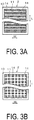
- FIGS. 3A and 3B are cross-sectional vertical views illustrating an example of the cell.
- FIG. 3A a similar effect as in FIGS. 2A and 2B can be obtained even when gas-flow passages 14 for discharging gas from the cell 2 are formed linearly in the width direction W of the cell 2 on the solid electrolyte side of the outer electrode layer 11.
- a plurality of gas-flow passages 14 can be formed linearly in the width direction W of the cell 2 by way of forming a plurality of the resin layers described above linearly in the width direction W of the cell 2.
- FIG. 3B a similar effect as in FIGS. 2A and 2B can be obtained even when the gas-flow passages 14 for discharging gas from the cell 2 are formed as a grid on the solid electrolyte side of the outer electrode layer 11.
- gas-flow passage 14 is not limited to what is illustrated in FIGS. 2B and 3 , but can be formed as a V-shaped gas flow passage, for example.
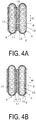
- FIG. 4A is a cross-sectional horizontal view illustrating yet another example of a cell stack.
- FIG. 4B is a cross-sectional horizontal view illustrating an example of the cell stack of the present embodiment.
- FIG. 4A illustrates that the cell stack including a gas-flow passage 15 for discharging gas from the cell 2 at the interconnector 12 side of one cell 2 of the outer electrode layer 11 of the other cell 2.
- the gas-flow passages 15 are semi-circular in the cross sections and six of these are formed linearly in the cell 2 in the lengthwise direction L.
- the gas-flow passage 15 passage is formed on the interconnector 12 side of the one cell 2 by the resin constituting the resin layer decomposing and dispersing, and the interconnector 12 of the one cell 2 adjacent to the other cell 2 and the outer electrode layer 11 of the other cell 2 can be connected electrically by being directly bonded.
- the oxygen generated by the outer electrode layer 11 can be expelled to the outside via the gas-flow passage 15, and electrolysis performance can be improved because the area of the outer electrode layer 11 present on the surface of the solid electrolyte 4 is large.
- the gas-flow passage can be formed in the middle portion of the outer electrode layer 11, although this is not illustrated in the drawings.
- a cell 2 on which no outer electrode layer 11 is formed is used, the paste constituting the outer electrode layer 11 is applied to the interconnector 12 of the one cell 2, and the paste constituting the outer electrode layer 11 is applied to the solid electrolyte layer surface of the other cell 2 adjacent to the one cell 2.
- the faces of the one cell and the other cell on which the paste constituting the outer electrode layer 11 has been applied are bonded together via the resin layer and thermally treated.
- the gas-flow passage 15 is formed in the middle portion of the outer electrode layer 11 by the resin constituting the resin layer decomposing and dispersing, and the interconnector 12 of the one cell 2 adjacent to the other cell 2 and the outer electrode layer 11 of the other cell 2 can be connected electrically by being directly bonded.
- the outer electrode layer 11 of the other cell 2 includes a porous layer 17 on the solid electrolyte layer 10 side, the porous layer 17 having a higher porosity than the interconnector 12 side of the one cell. And the pores in the porous layer 17 constitute the gas-flow passage by being continuous.
- the outer electrode layer 11 has higher porosity on the solid electrolyte side by way of having a two-layer structure of a low porosity layer 16 with a lower porosity than the porous layer 17 and a porous layer 17 with a high porosity.
- a cell stack With such a cell stack, first, a cell 2 on which no outer electrode layer 11 is formed is used, a first paste constituting the outer electrode layer 11 is applied on the interconnector 12 of the one cell 2, and a second paste (made from a resin containing more pore-imparting agents than the first paste) constituting the outer electrode layer 11 is applied to the solid electrolyte layer surface of the other cell 2 adjacent to the one cell 2.
- a second paste made from a resin containing more pore-imparting agents than the first paste constituting the outer electrode layer 11 is applied to the solid electrolyte layer surface of the other cell 2 adjacent to the one cell 2.
- the faces on which the paste constituting the outer electrode layer 11 are bonded together and thermally treated. Thereby, many pores are formed by the decomposition and dispersion of the pore-imparting agent made from the resin.
- the porous layer 17 with a higher porosity than the interconnector 12 side of the one cell 2 can be formed on the solid electrolyte layer 10 side of the outer electrode layer 11 of the other cell 2, and the interconnector 12 of the one cell 2 adjacent to the other cell 2 and the outer electrode layer 11 of the other cell 2 can be connected electrically by being bonded.
- the oxygen generated with the outer electrode layer 11 can be discharged efficiently via the gas-flow passage.
- the outer electrode layer 11 of the other cell 2 includes a porous layer on the solid electrolyte layer 10 side, with the porous layer including pores having a larger average diameter (higher porosity) than that of the interconnector 12 of the one cell 2.
- FIGS. 5A and 5B are external perspective views illustrating an example of the cell stack device of the present embodiment.
- a cell stack device 18 illustrated in FIG. 5A includes the cell unit 1 illustrated in FIG. 1A and a heating body (a heater or the like) for heating the middle portion side of the cells 2 in the longitudinal direction.
- a heating body a heater or the like
- the cell stack device 18 illustrated in FIG. 5A is provided with a heating body 19 for heating the middle portion side of the cells 2 in the longitudinal direction.
- the temperature of the cells 2 can be heated to a range from 600 to 1000°C and an electrolysis reaction can be generated by actuating the heating body 19.
- FIG. 5A illustrates an example of the heating body 19 being provided in the middle portion side of the cells 2 in the longitudinal direction and being positioned in the middle portion in the direction that the cells 2 are aligned in the cell stack 7, but the heating body 19 can also be provided in the middle portion side of all the cells 2 in the longitudinal direction.
- the heating body 19 faces the middle portion side of the cell 2 in the longitudinal direction but does not face the one end portion side and the other end portion side of the cell 2.
- the cells 2 are fixed to the first manifold 3 and the second manifold 5 using a sealing material (the cells 2 and the sealing material in the fixing region may be collectively referred below as a fixing section). Therefore, when the heating body 19 is provided so as to heat the entire cells 2, a thermal resistant sealing material (such as glass) must be used for fixing, but damage is liable to occur to the sealing material or the cells 2 due to thermal stress generated by a difference in thermal expansion or the like between the cells 2 and the sealing material. Consequently, increases in the fixing section temperature can be suppressed and the thermal stress generated on the fixing section can be reduced by the heating body 19 not facing the one end portion side and the other end portion side of the cells 2.
- a thermal resistant sealing material such as glass
- sealing material with a not particularly high thermal resistance (such as resin) can be used for fixing, the types of sealing material can be increased, and the number of selections for the sealing material can be increased.
- FIG. 6 is an external perspective view illustrating another example of the cell stack device of the present embodiment.
- a first manifold 22 and a second manifold 23 extend along the cell 2 in the longitudinal direction.
- the first manifold 22 and the second manifold 23 are provided so as to enclose the cell stack 7, and the first manifold 22 and the second manifold 23 are U-shaped in the plan view.
- the cell 2 To generate an electrolysis reaction in the cell 2 as described above, the cell 2 must be heated to a range from 600 to 1000°C and that temperature must be maintained.
- the first manifold 22 and the second manifold 23 extend along the longitudinal direction of the cell 2 and the cell stack 7 is enclosed, the temperature of the cell stack 7 can be maintained at a high temperature and an efficient electrolysis reaction can be generated.
- the first manifold 22 and the second manifold 23 are provided with a slight gap between these. It is assumed that each manifold is deformed by thermal expansion by the temperature of the cell stack 7 being high and then the heat being transferred to each manifold.
- each manifold 22 and the second manifold 23 are disposed without a gap, each manifold is liable to be further deformed due to thermal expansion, but by being disposed with a gap in this manner, large deformations can be suppressed even when each manifold experiences a slight deformation.
- FIG. 7 is an external perspective view illustrating another example of the cell stack device of the present embodiment. Compared to the cell stack device 20 illustrated in FIG. 5B , one point of difference is that a cooling member 25 for cooling the cells 2 is provided on the other end portion of the cells 2 (the second manifold 5 side).
- the heating body 19 does not face the one end portion and the other end portion of the cells 2, and damage or the like occurring on the fixing section between the one end and the other end of the cells 2 and each manifold can be more effectively suppressed by providing a cooling member 25 for cooling the cells 2 on at least the one end portion and the other end portion of the cells 2.
- the cell stack device 24 of the present embodiment generates gas containing hydrogen by an electrolysis reaction of the water vapor supplied to the first manifold 3 in cells 2 in which the temperature has been increased by the heating body 19, and then causes the gas containing the hydrogen to flow to the second manifold 5.
- the temperature of the hydrogen flowing to the second manifold 5 is high, and the temperature on the other end portion side on the second manifold 5 side of the cells 2 tends to be higher than that of the one end portion side on the first manifold 3 side of the cells 2. Consequently, a cooling member 25 is preferably provided on the other end portion side of the cells 2 (the second manifold 5 side) to more effectively suppress damage to the fixing section of the cells 2 and the manifold.
- a flat cooling member 25 is depicted as the cooling member 25, but the cooling member 25 is not particularly limited as long as the end portion side of the cells 2 can be cooled, and for example fins, a structure forming flow paths in which refrigerant flows, or the like can be suitable used.
- water for example, can be used as the refrigerant when a structure forming flow paths in which a refrigerant flows is used as the cooling member 25.
- an efficient cell stack device 24 can be achieved by supplying the water vapor to the first manifold 3 via the introduction pipe 4 when the water is evaporated to become water vapor using the heat from the cell 2.
- FIGS. 8A and 8B are external perspective views illustrating an example of a cell unit device of the present embodiment.
- Cell unit devices 26, 27 illustrated in FIGS. 8A and 8B are configured by arranging five cell units 1 illustrated in FIG. 1A in parallel in the vertical direction. Note that in the cell unit device 26 illustrated in FIG. 8A , the cell units 1 are arranged in parallel (arranged with the same orientation) so that at least a portion of the first manifolds 3 and the second manifolds 5 overlap each other in the plan view.
- the cell unit device 27 illustrated in FIG. 8B depicts an example of the cell units 1 being disposed such that the first manifolds 3 and the second manifolds 5 alternate in the vertical direction and the cell units 1 are arranged in parallel so that at least a portion of the first manifolds 3 and the second manifolds 5 overlap in the plan view (arranged to be opposite in orientation).
- Such a cell unit device 26, 27 can generate a large volume of hydrogen because the cell units 1 of the present embodiment are arranged in parallel so that the cells 2 extend in the horizontal direction.
- each manifold is disposed so that at least a portion overlaps in the plan view, so the cell unit device 26, 27 can be easily assembled. Note that each manifold may be preferably placed so as to overlap each other in entirety.
- the temperature distribution in which the temperature of the other end portion on the second manifold 5 side is higher than that of the one end portion on the first manifold 3 side tends to be generated.
- the temperature distribution becomes more significant, and the fixing section (sealing material) in the cell 2, particularly between the other end portion and the second manifold 5, is liable to become damaged.
- an improved cell unit device 27 that is more reliable can be achieved the generation of a temperature distribution or the range of the temperature distribution can be suppressed and damage to the fixing section of the cell 2 and the manifolds can be suppressed by way of configuring the cell unit 1 by disposing the first manifold 3 and the second manifold 5 to alternate in the vertical direction as in the cell unit device 27 illustrated in FIG. 8B .
- the cell units 1 in order to arrange the cell units 1 in parallel in the vertical direction, the cell units 1 (manifolds) may be disposed with a gap between the units or can be arranged in parallel with an insulating material or the like between the units.
- the cell unit device 26, 27 described above illustrates an example of a configuration in which an introduction pipe 4 or a recovery pipe 6 connected to each manifold and water vapor is supplied or gas containing hydrogen is recovered via these, but a simpler structure can also be achieved by a structure in which the cell units 1 are arranged in parallel.
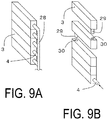
- FIGS. 9A and 9B are external perspective views illustrating connected states of a first manifold excerpted from the cell unit device of the present embodiment.
- FIG. 9A illustrates a configuration in which the introduction pipes 4 connected to the first manifolds 3 are connected to each other by a single connecting pipe 28.
- the connecting pipe 28 and introduction pipe 4 can be provided with an orifice or the like in addition to suitable varying the diameters of the connecting pipe 28 and the introduction pipe 4.
- each manifold 3 is provided with a linking pipe 29 and a linking hole 30 for the linking pipe 29 to be inserted and fixed, and first manifolds 3 can be easily linked to each other by inserting and fixing the linking pipes 29 into the linking holes 30.
- the linking pipe 29 and the linking hole 30 are preferably configured to be provided on one end portion and the other end portion, in order, on the first manifold 3 in the longitudinal direction (direction that the cells 2 are aligned) so that the water vapor is efficiently distributed to each first manifold 3.
- the water vapor supplied from a single introduction pipe 4 can be efficiently distributed to each first manifold 3.
- FIGS. 10A and 10B are external perspective views illustrating another example of the cell unit device of the present embodiment.
- At least some cell units 1 of the cell units 1 include a heating body 32 (such as a heater) for heating the middle portion side of the cells 2 in the longitudinal direction, and the heating body 32 faces the middle portion side of the cells 2 in the longitudinal direction and does not face the one end portion and the other end portion of the cells 2.
- a heating body 32 such as a heater
- the cell stack device 31 illustrated in FIG. 10A is provided with the heating body 32 for heating the middle portion side of the cells 2 in the longitudinal direction.
- the temperature of the cell 2 can be heated to a range from 600 to 1000°C and an electrolysis reaction can be generated by actuating the heating body 32.
- FIG. 10A illustrates an example of the heating body 32 being provided on the cell stack that is in the topmost cell unit in the middle portion of the cells 2 in the longitudinal direction and being positioned in the middle portion in the direction that the cells 2 are aligned, but the heating body 32 can also be provided in the middle portion of all the cells 2 in the longitudinal direction. Note that the heating body 32 may also be provided for each cell unit.
- temperature increases in the fixing section can be suppressed and the thermal stress generated on the fixing section can be reduced by the heating body 32 not facing the one end portion side and the other end portion side of the cells 2.
- damage to the cells 2 and the sealing material can be suppressed, and reliability can be improved.
- the heating body 34 is disposed so as to enclose the whole outer periphery of the plurality of cell units 1.
- cell stack devices 20 including the heating body 19 disposed so as to enclose the outer periphery of a single cell unit 1, as illustrated in FIG. 5B , can be disposed in parallel, but in this case, the cell unit device is liable to be larger by the heating body 19 being bulky and by the possibility of the manifolds being larger in order to connect to each cell unit 1.
- making the cell unit device larger can be suppressed by arranging a cell units 1 in parallel and then disposing a heating body 34 so as to surround the entire outer periphery of the plurality of cell units 1.
- a module of the present embodiment can be achieved by housing the cell unit 1, cell stack device 18, 20, 21, 24, and cell unit device 26, 27, 31, 33, as described above, in a housing container.
- FIG. 11 is a schematic view illustrating an example of the module of the present embodiment.
- a module 35 illustrated in FIG. 11 the cell unit device 26 illustrated in FIG. 8A is housed in a rectangular parallelepiped-shaped housing container 36.
- insulating material 37 for maintaining the interior of the housing container 36 at a high temperature is provided on the inner side surface of the housing container 36.
- the insulating material 37 may be provided on the outer side face of the housing container 36.
- pipes to supply water vapor to the cell unit device, recovery pipes for gas, and the like are omitted.
- a heating body such as a heater is preferably disposed separately from the cell unit device 26 in the housing container 36, for example, because no heating body is provided in the cell unit device 26.
- FIG. 11 illustrates an example in which a heater, which is the heating body 38, is provided on top of the cell unit device 26 separate from the cell unit device 26. Note that the location where the heating body 38 is disposed is not limited to the top of the cell unit device 26, but may also be provided between cell units 1.
- the description above used the cell 2 provided with the inner electrode layer 9, the solid electrolyte layer 10, and the outer electrode layer 11 on the support body 8 as the cell 2, but a cell with a configuration in which the inner electrode layer 9 also serves as the support body 8 and that is provided with the solid electrolyte layer 10 and the outer electrode layer 11 on the inner electrode layer 9 can also be used.
- a so called off-gas recycling type fuel cell can be achieved that reuses recovered fuel gas by supplying a fuel gas containing hydrogen from the first manifold 3, 22 and recovering the excess fuel gas not used by the cell 2 by the second manifold 5, 23.
Description
- The present invention pertains to a cell unit, a cell stack device, a cell unit device, and a module.
- Currently, a water electrolysis device using a cell has been proposed as technology to manufacture hydrogen (H2).
- A device that generates hydrogen by an electrode body being provided on both sides of a polymer electrolyte membrane, stacking a unit made by disposing a power feeding body on both of these sides, and decomposing water supplied to an outer electrode layer side of the power feeding unit by applying a voltage to both ends in the direction of the stack is known as such an water electrolysis device (see
Patent Document 1 for example). -
Patent Document 2 discloses a solid electrolyte fuel cell system, wherein each tubular fuel cell with solid electrolyte, whose two ends are left open, is formed from at least an air electrode, electrolyte, and fuel electrode put one over another, and a plurality of such fuel cells are put in connection through spacers made of metal or metal oxide. -
Patent Document 3 discloses an electrochemical reactor cell stack being a structure in which electrochemical reactor cells having a tube structure constituted of an anode (a fuel electrode), a dense ion conductor (electrolyte), and a cathode (an air electrode) are provided. Each tube type cell is electrically connected in parallel or in series with the other by a conductive connector. - In addition, in recent years a high temperature electrolysis method using a cell provided with a solid oxide electrolyte membrane (SOEC) has been proposed as another method for manufacturing hydrogen.
-
Patent Document 4 discloses a fuel cell having a container with a gas flow path along its length and a fuel cell stack formed by stacking a plurality of fuel cells spaced apart (cf. Abstract). This document further discloses that the container comprises a power generating chamber for containing the fuel cells and a combustion chamber for combusting excessive fuel gas emitted from the fuel cells and oxygen-containing gas emitted from the power generating chamber (cf. Abstract). -
Patent Document 5 discloses that an electrolyser for producing hydrogen gas comprises electrolysis cells in communication with a distributor of steam and one or more energy guides disposed within the electrolyser for directing radiant energy to irradiate the plurality of electrolysis cells so the electrolysis cells absorb thermal energy to facilitate electrolysis in the electrolysis cells (cf. Abstract). This document further discloses that the electrolyser also comprises a hydrogen gas collector for collecting hydrogen gas generated by the electrolysis cells (cf. Abstract). -
Patent Document 6 discloses that a hollow electrode electrochemical device (HEED) comprises an inner electrode chamber, inner current collector, inner electrode, electrolyte, outer electrode, outer current collector, and outer electrode chamber (cf. Abstract). This document further discloses that a system comprises a plurality of HEED, arranged in a parallel array, mechanically supported by one or more header plates, where a primary header plate encompasses a portion of a gas manifold connected to the inner chamber of the HEED, and that the HEED pass through the primary header plate, into the primary manifold chamber wherein electronic connections are formed between the inner current collector and outer current collectors of the HEED to allow for series, parallel, or series-parallel electrical configurations (cf. Abstract). -
- Patent Document 1: Japanese Unexamined Patent Application Publication No.
2012-41568A - Patent Document 2:
JP H05 101842 A - Patent Document 3:
JP 2007/265650 A - Patent Document 4:
JP 2008-2835286 A - Patent Document 5:
WO 2010/057257 A1 - Patent Document 6:
US 2010/086824 A1 - However, there is room for improvement with regards to a specific configuration, in particular for a water electrolysis device using a cell provided with a solid oxide electrolyte (SOEC).
- Therefore, an object of the present invention is to provide a cell unit, a cell stack device, a cell unit device, and a module having more specific configurations.
- The present invention provides a cell unit according to
claim 1, a cell stack device according toclaim 4, a cell unit device according toclaim 8 and a module according toclaim 13 and claim 14. Further advantageous embodiments are disclosed in the dependent claims. - A cell unit of the present invention can easily supply gas to a cell and can easily recover gas discharged from the cell.
- In addition, a cell stack device of the present invention can improve reaction efficiency because the temperature in the middle portion side of the cell with good reaction efficiency can be raised by way of a heating body.
- In addition, a cell unit device of the present invention can easily recover the gas discharged from the cell with a simple configuration.
- Furthermore, a module of the present invention can be a module with improved reaction efficiency.
-
-
FIG. 1A is an external perspective view illustrating one example of a cell unit of the present embodiment.FIG. 1B is a cross-sectional view illustrating a cross section of an example of a cell stack along the line x-x depicted inFIG. 1A with a portion omitted. -
FIG. 2A is a cross-sectional horizontal view illustrating another example of a cell stack.FIG. 2B is a cross-sectional vertical view along the line y-y inFIG. 2A . -
FIGS. 3A and 3B are cross-sectional vertical views illustrating an example of a cell. -
FIG. 4A is a cross-sectional horizontal view illustrating yet another example of a cell stack.FIG. 4B is a cross-sectional horizontal view illustrating an example of a cell stack of the present embodiment. -
FIGS. 5A and 5B are external perspective views illustrating an example of a cell stack device of the present embodiment. -
FIG. 6 is an external perspective view illustrating another example of a cell stack device of the present embodiment. -
FIG. 7 is an external perspective view illustrating yet another example of a cell stack device of the present embodiment. -
FIGS. 8A and 8B are external perspective views illustrating an example of a cell unit device of the present embodiment. -
FIGS. 9A and 9B are external perspective views illustrating a connected state of a first manifold excerpted from the cell unit device of the present embodiment. -
FIGS. 10A and 10B are external perspective views illustrating another example of a cell unit device of the present embodiment. -
FIG. 11 is a schematic view illustrating an example of a module of the present embodiment. -
FIG. 1A is an external perspective view illustrating one example of a cell unit of the present embodiment.FIG. 1B is a cross-sectional view illustrating a cross section of an example of a cell stack. - The
cell unit 1 illustrated inFIG. 1A is provided with acell stack 7 formed bycolumnar cells 2 being arranged, the cells include an inner electrode layer, a solid oxide solid electrolyte, and an outer electrode layer and include a distribution hole that passes from one end to the other end in the longitudinal direction. Note that the following describes an example of an electrolysis cell to perform electrolysis on water (water vapor) as thecell 2. - In addition, in the
cell unit 1 illustrated inFIGS. 1 , thecell stack 7 formed by thecells 2 arranged in one row is depicted, but thecell stack 7 can be formed by being provided with a plurality of rows or a plurality of columns ofcells 2. - The
cells 2 are fixed to afirst manifold 3 for one end portion to supply water vapor to the distribution hole. Note that anintroduction pipe 4 for introducing water vapor to the interior of thefirst manifold 3 is connected to thefirst manifold 3. Thecell 2 is described later, but here, when thecell 2 is formed by containing Ni, for example, the Ni is liable to be oxidized by the water vapor when only water vapor is supplied to thecell 2. When Ni is oxidized, a support body or the inner electrode layer containing Ni will undergo a volume change because of the oxidization and a solid electrolyte can be damaged due to excessive stress being generated on the solid electrolyte. Then, cross leakage in the solid electrolyte occurs and the performance of thecell 2 is significantly degraded. Therefore, in order to prevent this occurrence, oxidization of thecell 2 can be suppressed by adding a small amount of hydrogen to the water vapor. - Meanwhile, the other ends of the
cells 2 are fixed to asecond manifold 5 for recovering gas containing hydrogen discharged from the distribution hole. Note that arecovery pipe 6 for recovering the gas containing hydrogen is connected to thesecond manifold 5. - In other words, the
cell unit 1 is configured to include thecells 2, thefirst manifold 3 to which one ends portion of thecells 2 are fixed, and thesecond manifold 5 to which the other ends of thecells 2 are mounted. The water vapor flowing to thefirst manifold 3 via theintroduction pipe 4 is made into a gas containing hydrogen by way of electrolysis while flowing in thecells 2. The gas containing hydrogen is recovered by therecovery pipe 6 after flowing to thesecond manifold 5. By making thecell unit 1 into such a configuration, water vapor can be easily supplied to thecells 2 and the gas containing hydrogen discharged from thecells 2 can be easily recovered with a very simple configuration. - Here, the
cell unit 1 illustrated inFIG. 1A is a configuration in which thecells 2 are disposed in the horizontal direction. If thecells 2 are provided so as to be erect, damage or the like to thecells 2 is liable to occur by the weight of thesecond manifold 5 positioned above thecells 2 being applied, but as illustrated inFIG. 1A , damage or the like to thecells 2 can be prevented from occurring with a configuration in which thecells 2 are disposed in the horizontal direction. - When a cell comprising a solid oxide solid electrolyte (SOEC cell) is used as the
cell 2, a portion or all of the water vapor supplied to thecell 2 is decomposed into hydrogen and oxygen by generating a reaction, described by the reaction formula below, in the inner electrode layer and the outer electrode layer by supplying the water vapor to thecell 2 while heating thecell 2 to a range from 600 to 1000°C and applying a voltage of 1.0 to 1.5 V (per cell). Note that the oxygen is discharged from the outer electrode layer, described below.
Inner electrode layer: H2O + 2e- → H2 + O2-
Outer electrode layer: O2 - → 1/2 O2 + 2e- - Below, the configuration of the
cell 2 is described usingFIG. 1B . Note thatFIG. 1B illustrates the cross-sectional view of thecell unit 1 illustrated inFIG. 1A with a portion thereof omitted. - As illustrated in
FIGS. 1A and 1B , thecell 2 is a hollow and flat plate, the cross section is a flat shape, and is provided with a porous, conductive support body (referred to as a support body below) 8 having an elliptical columnar shape when viewed as a whole. - The inside of the
support body 8 is formed so that distribution holes 13 with a suitable interval therebetween penetrate from one end to the other end along the length L of thecell 2. Thecell 2 has a structure by which various members are provided on thesupport body 8. Note that the distribution holes 13 may be circular in the horizontal cross section of thecell 2. - As understood from the shape illustrated in
FIG. 1B , thesupport body 8 is configured by a pair of flat faces n that are mutually parallel and side faces (arc sections) m connecting both ends of the pair of flat faces n. Both faces of the flat faces n are formed to be approximately parallel. A porousinner electrode layer 9 is provided so as to cover the surface of one of the flat faces n and both side faces m. Furthermore, a densesolid electrolyte layer 10 is layered so as to cover theinner electrode layer 9. In addition, a porousouter electrode layer 11 is layered on thesolid electrolyte layer 10 so as to face theinner electrode layer 9. The portion where theinner electrode layer 9, thesolid electrolyte layer 10, and theouter electrode layer 11 overlap is an element portion a (electrolytic element part). In addition, aninterconnector 12 is layered on the other flat face n on which noinner electrode layer 9 and nosolid electrolyte layer 10 are layered. - As is clear from
FIG. 1B , thesolid electrolyte layer 10 extends to the other flat face n side via the arc shaped side face m coupling both ends of the flat faces n, and both end faces of theinterconnector 12 abut both end faces of theinner electrode layer 9 and thesolid electrolyte layer 10. Note that both end portions of theinterconnector 12 can be disposed so as to be stacked on both end portions of thesolid electrolyte layer 10. - Note that a cohesion layer for firmly bonding the
interconnector 12 and thesupport body 8 can be provided between the interconnector 12 and thesupport body 8. In addition, an anti-reaction layer can be provided between thesolid electrolyte layer 10 and theouter electrode layer 11, the anti-reaction layer is for suppressing reaction products having high resistance generated by a component of thesolid electrolyte layer 10 reacting with a component of theouter electrode layer 11. - Here, an electrolysis reaction can be generated in the
cell 2 by causing water vapor to flow in the distribution holes 13 in thesupport body 8, heating to the predetermined actuation temperature described above, and applying the predetermined voltage described above between theinner electrode layer 9 and theouter electrode layer 11. Note that the voltage is applied by a current flowing to thecell 2 via theinterconnector 12 stacked on thesupport body 8. Below, each configuration constituting thecell 2 is described in order. - The
support body 8 is preferably formed from, for example, an iron group metal component and a specific inorganic oxide (such as a rare earth element oxide) because thesupport body 8 must be permeable to transmit the water vapor in order for the water vapor to penetrate to thesolid electrolyte layer 10 and must be conductive for the current to flow via theinterconnector 12. - Examples of the iron group metal component include an iron group metal simple substance, an iron group metal oxide, an iron group metal alloy or alloy oxide, and the like. More specifically, Fe, Ni, and Co can be used as the iron group metal, for example, and materials containing at least one of Ni and NiO as the iron group component or iron group metal oxide are preferable specifically because these are inexpensive. Note that Fe and Co may also be contained in addition to at least one of the Ni and the NiO. Note that NiO is reduced by the H2 generated by the electrolysis reaction, and a portion or all of the NiO is present as Ni.
- In addition, the rare earth element oxide is used to bring the thermal expansion coefficient of the
support body 8 closer to the thermal expansion coefficient of thesolid electrolyte layer 10, and the rare earth element oxide containing at least one element selected from the group consisting of Y, Lu, Yb, Tm, Er, Ho, Dy, Gd, Sm, and Pr can be used in combination with the iron group component. Specific examples of such a rare earth element oxide include Y2O3, Lu2O3, Yb2O3, Tm2O3, Er2O3, Ho2O3, Dy2O3, Gd2O3, Sm2O3, and Pr2O3. Y2O3 and Yb2O3 are preferable because these have virtually no reaction with nor form a solid solution with oxides of the iron group metal, the thermal expansion coefficients are approximately the same as thesolid electrolyte layer 10, and these are inexpensive. - Here, in terms of maintaining favorable conductivity for the
support body 8 and of making the thermal expansion coefficient to be near thesolid electrolyte layer 10, the volume ratio of the iron group metal component to the rare earth element oxide component is preferably from 35:65 to 65:35 volume percentage after firing-reduction. Note that when using Ni as the iron group metal component and Y2O3 as the rare earth element oxide component, it is preferably that the content of Ni and Y2O3 is such that Ni/(Ni + Y) is from 79 to 93 mol%. Note that other metal components and oxide components may be used in thesupport body 8 as long as the required characteristics are not impaired. - In addition, the
support body 8 preferably has, in general, an apparent porosity of 30% or greater, specifically in the range of 35% to 50% because thesupport body 8 must have water vapor permeability. In addition, the conductivity of thesupport body 8 is preferably 50 S/cm or greater, more preferably 300 S/cm or greater, and even more preferably 440 S/cm or greater. - Note that the length of the flat face n of the support body 8 (the length of the
support body 8 in the width direction) is, in general, preferably from 15 to 35 mm, the length of the side face m (arc length) is preferably from 2 to 8 mm, and the thickness of the support body 8 (the thickness between both faces of the flat face n) is preferably from 1.5 to 5 mm. - The
inner electrode layer 9 causes an electrode reaction to occur and is preferably formed from a porous, electrically conductive ceramic that is publicly known. For example, the inner electrode layer can be formed from a ZrO2 forming a solid solution with the rare earth element oxide or a CeO2 forming a solid solution with the rare earth element oxide and at least one of Ni and NiO. Note that the rare earth elements described as examples for thesupport body 8 can be used as the rare earth element, and the rare earth element can be formed from a ZrO2 (YSZ) forming a solid solution with Y2O3 and at least one of Ni and NiO. - The volume ratio of the content of a ZrO2 forming a solid solution with the rare earth element oxide or a CeO2 forming a solid solution with the rare earth element oxide in the
inner electrode layer 9 to the content of Ni or NiO is preferably from 35:65 to 65:35 volume percentage after firing-reduction. Furthermore, the apparent porosity of theinner electrode layer 9 is no less than 15% and in particular preferably in the range of 20 to 40%, and the thickness thereof is preferably from 1 to 30 µm. For example, if the thickness of theinner electrode layer 9 is too small, performance is liable to be reduced, and if the thickness is too large, peeling or the like is liable to occur due to the difference in thermal expansion between thesolid electrolyte layer 10 and theinner electrode layer 9. - In addition, in the example in
FIG. 1B , theinner electrode layer 9 extends from one flat face n (the flat face n positioned on the left in the figure) to the other flat face n (the flat face n positioned on the right in the figure) via the side face m, but theinner electrode layer 9 may be formed only on the flat face n on the side where theouter electrode layer 11 is provided, for example, because it is sufficient for theinner electrode layer 9 to be formed in a position facing theouter electrode layer 11. In other words, a structure may be such that theinner electrode layer 9 is provided only on a flat face n, and thesolid electrolyte layer 10 is formed on theinner electrode layer 9, on both side faces m, and on the other flat face n where noinner electrode layer 9 is formed. - The
solid electrolyte layer 10 preferably uses a dense ceramic made from partially stabilized or stabilized ZrO2 containing a rare earth element oxide such as Y2O3, Sc2O3, or Yb2O3 at from 3 to 15 mol%. In addition, Y is preferable as the rare earth element in light of being inexpensive. Furthermore, in terms of preventing the transmission of water vapor, the relative density (according to the Archimedes method) of thesolid electrolyte layer 10 is preferably 93% or greater, and a dense material of 95% or greater relative density is particularly desirable. The thickness of thesolid electrolyte layer 10 is preferably from 5 to 50 µm. - As described above, an anti-reaction layer can be provided between the
solid electrolyte layer 10 and theouter electrode layer 11, described below, for the purpose of firming the bond between thesolid electrolyte layer 10 and theouter electrode layer 11 and of suppressing the reaction products having high electric resistance generated by the components in thesolid electrolyte layer 10 reacting with the components in theouter electrode layer 11. - The anti-reaction layer can be formed with a composition containing Ce (cerium) and another rare earth element, and for example, preferably includes the composition of (CeO2)1-x(REO1.5)x, where RE is at least one of Sm, Y, Yb, and Gd, and x is a value satisfying 0 < x ≤ 0.3. Furthermore, in terms of reducing electric resistance, using Sm and Gd as RE is preferable, and for example, the composition is preferably made from a CeO2 forming a solid solution with Sm01.5 or GdO1.5 at from 10 to 20 mol%.
- In addition, two layered anti-reaction layer can be formed for the purposes of firmly bonding the
solid electrolyte layer 10 and theouter electrode layer 11 and further suppressing reaction products having high electric resistance generated by the components in thesolid electrolyte layer 10 reacting with the components in theouter electrode layer 11. - The
outer electrode layer 11 is preferably formed from an electrically conductive ceramic made of a so called ABO3 type perovskite-type oxide. Such a perovskite-type oxide is preferably a transition metal-type perovskite oxide, in particular at least one type of a LaMnO3 based oxide, a LaFeO3 based oxide, and a LaCoO3 based oxide with Sr and La coexisting in the A site, and LaCoO3 based oxide is particularly preferable in terms of high electric conductivity at the actuation temperature of 600 to 1000°C. Note that Sr and La may be present in the A site, and Fe (iron) or Mn (manganese) together with Co (cobalt) may also be present in the B site in the perovskite-type oxide described above. - In addition, the
outer electrode layer 11 must be permeable to oxygen gas, and therefore the electrically conductive ceramic (perovskite-type oxide) forming theouter electrode layer 11 preferably has an apparent porosity of 20% or greater and more preferably in the range of 30 to 50%. Furthermore, the thickness of theouter electrode layer 11 is preferably from 30 to 100 µm in light of the conductivity of thecell 2. - In addition, the
interconnector 12 is stacked on the flat face n on the side of thesupport body 8 opposite to theouter electrode layer 11 side. - Although the
interconnector 12 is preferably formed from an electrically conductive ceramic, theinterconnector 12 must be resistant to reduction and oxidation in order to be in contact with the fluid containing hydrogen and the fluid containing oxygen. Consequently, in general, a lanthanum chromite-based perovskite-type oxide (LaCrO3 based oxide) is preferably used as the electrically conductive ceramic resistant to reduction and oxidation. Furthermore, using a LaCrMgO3 based oxide with Mg present in the B site is particularly preferable for the purpose of bringing the thermal expansion coefficient closer to that of thesupport body 8 and thesolid electrolyte layer 10. Note that the amount of Mg can be suitable adjusted to be specifically from 10 to 12 ppm/K so that the thermal expansion coefficient of theinterconnector 12 is near the thermal expansion coefficients of thesupport body 8 and thesolid electrolyte layer 10. - In addition, as described above, the cohesion layer for reducing the difference between the thermal expansion coefficients of the
interconnector 12 and thesupport body 8 can be provided between the interconnector 12 and thesupport body 8. - Such a cohesion layer can have a composition similar to the
inner electrode layer 9. For example, the cohesion layer can be formed from at least one of a group consisting of a rare earth element oxide, a ZrO2 forming a solid solution with the rare earth element oxide, or a CeO2 forming a solid solution with the rare earth element oxide and at least one of Ni and NiO. More specifically, the cohesion layer can be formed from, for example, a composition made of Y2O3 and at least one of Ni and NiO, a composition made of a ZrO2 forming a solid solution with Y2O3 (YSZ) and at least one of Ni and NiO, or a composition made of a CeO2 forming a solid solution with an oxide such as Y, Sm, Gd, or the like and at least one of Ni and NiO. Note that the volume ratio of the content of the ZrO2 forming a solid solution with the rare earth element oxide or the CeO2 forming a solid solution with the rare earth element oxide to the content of Ni or NiO is preferably from 40:60 to 60:40 volume percentage after firing-reduction. - Note that in
FIG. 1B , theinterconnector 12 of the onecell 2 is bonded to theouter electrode layer 11 of theother cell 2 adjacent to the onecell 2, thereby configuring thecell stack 7 in which thecells 2 are electrically connected together. - With such a
cell stack 7, thecell 2 on which noouter electrode layer 11 is formed is used, a paste constituting theouter electrode layer 11 is applied on theinterconnector 12 of the onecell 2, the paste forming theouter electrode layer 11 is applied on thesolid electrolyte layer 10 of theother cell 2 adjacent to the onecell 2, then the faces on which the paste has been applied are bonded and then thermally treated. Thereby, theinterconnector 12 of the onecell 2 and theouter electrode layer 11 of theother cell 2, thesecells 2 being adjacent to each other, can be connected electrically by being directly bonded. Accordingly, thecell stack 7 can be made smaller. - Furthermore, although omitted from
FIGS. 1A and 1B , an electrically conductive member for the end portion including an introduction unit for current to flow to the cell stack 7 (cell 2) is preferably disposed on both ends of thecell stack 7. - Note that it is sufficient for the
interconnector 12 of the onecell 2 to be electrically connected to theouter electrode layer 11 of theother cell 2, and may, for example, be electrically connected via an electrically conductive member made from metal or the like. -
FIG. 2A is a cross-sectional horizontal view illustrating another example of the cell stack.FIG. 2B is a cross-sectional vertical view along the line y-y inFIG. 2A . Note that twocells 2 constituting the cell stack are selected to be illustrated inFIG. 2A . - As described above, because the
outer electrode layer 11 has a predetermined porosity, a gas-flow passage is formed in theouter electrode layer 11 by many pores in communication. Therefore, gas can be discharged from thecell 2 and thecells 2 can be electrically connected using a simple structure that can expel oxygen generated in the electrolysis reaction to the outside of theouter electrode layer 11 via the gas-flow passage formed in theouter electrode layer 11. - However, it is preferable to provide a flow path in which the oxygen flows in order to more efficiently expel the oxygen generated in the electrolysis reaction.
- Therefore, in the
cell 2 illustrated inFIGS. 2A and 2B , a gas-flow passage 14 for discharging oxygen from thecell 2 is provided on the solid electrolyte side of theouter electrode layer 11. Note that inFIGS. 2A and 2B , the gas-flow passage 14 has a semi-circular cross-section shape, and as illustrated inFIG. 2B , is formed to be linear in the lengthwise direction L of thecell 2. Six passages are formed in thecell 2 disposed at predetermined intervals in the width direction. - Thereby, the oxygen generated with the
outer electrode layer 11 can be discharged efficiently via the gas-flow passage 14. - For such a cell stack, first, the
cell 2 on which noouter electrode layer 11 is formed is used, and then a paste constituting theouter electrode layer 11 is applied to theinterconnector 12 of the onecell 2. Next, a resin paste is applied to and then dried on thesolid electrolyte layer 10 of theother cell 2 adjacent to the onecell 2, and then six linear resin layers are formed in the lengthwise direction L of thecell 2. Then, the paste constituting theouter electrode layer 11 is applied to thesolid electrolyte layer 10 of theother cell 2 in which the resin layer is formed, the faces of the one and theother cell 2 on which the paste constituting theouter electrode layer 11 has been applied are bonded together and thermally treated. Thereby, the gas-flow passage 14 is formed by the resin constituting the resin layer decomposing and dispersing, and theinterconnector 12 of the onecell 2 adjacent to theother cell 2 and theouter electrode layer 11 of theother cell 2 can be connected electrically by being directly bonded. -
FIGS. 3A and 3B are cross-sectional vertical views illustrating an example of the cell. - As illustrated in
FIG. 3A , a similar effect as inFIGS. 2A and 2B can be obtained even when gas-flow passages 14 for discharging gas from thecell 2 are formed linearly in the width direction W of thecell 2 on the solid electrolyte side of theouter electrode layer 11. In this case, a plurality of gas-flow passages 14 can be formed linearly in the width direction W of thecell 2 by way of forming a plurality of the resin layers described above linearly in the width direction W of thecell 2. - Furthermore, as illustrated in
FIG. 3B , a similar effect as inFIGS. 2A and 2B can be obtained even when the gas-flow passages 14 for discharging gas from thecell 2 are formed as a grid on the solid electrolyte side of theouter electrode layer 11. - Note that the gas-
flow passage 14 is not limited to what is illustrated inFIGS. 2B and3 , but can be formed as a V-shaped gas flow passage, for example. -
FIG. 4A is a cross-sectional horizontal view illustrating yet another example of a cell stack.FIG. 4B is a cross-sectional horizontal view illustrating an example of the cell stack of the present embodiment. -
FIG. 4A illustrates that the cell stack including a gas-flow passage 15 for discharging gas from thecell 2 at theinterconnector 12 side of onecell 2 of theouter electrode layer 11 of theother cell 2. The gas-flow passages 15 are semi-circular in the cross sections and six of these are formed linearly in thecell 2 in the lengthwise direction L. - With such a cell stack, first, six resin layers are linearly formed in the lengthwise direction L of the
cell 2 by using thecell 2 on which noouter electrode layer 11 is formed, applying a resin paste to theinterconnector 12 of the onecell 2, and drying the resin paste. Next, the paste constituting theouter electrode layer 11 is applied to theinterconnector 12 of the onecell 2 in which the resin layer is formed, and the paste constituting theouter electrode layer 11 is applied to the solid electrolyte layer surface of theother cell 2 adjacent to the onecell 2. Then, the faces of the one cell and the other cell on which the paste constituting theouter electrode layer 11 has been applied are bonded together and thermally treated. Thereby, the gas-flow passage 15 passage is formed on theinterconnector 12 side of the onecell 2 by the resin constituting the resin layer decomposing and dispersing, and theinterconnector 12 of the onecell 2 adjacent to theother cell 2 and theouter electrode layer 11 of theother cell 2 can be connected electrically by being directly bonded. - Thereby, the oxygen generated by the
outer electrode layer 11 can be expelled to the outside via the gas-flow passage 15, and electrolysis performance can be improved because the area of theouter electrode layer 11 present on the surface of thesolid electrolyte 4 is large. - Note that the gas-flow passage can be formed in the middle portion of the
outer electrode layer 11, although this is not illustrated in the drawings. For such a gas-flow passage, first, acell 2 on which noouter electrode layer 11 is formed is used, the paste constituting theouter electrode layer 11 is applied to theinterconnector 12 of the onecell 2, and the paste constituting theouter electrode layer 11 is applied to the solid electrolyte layer surface of theother cell 2 adjacent to the onecell 2. Next, the faces of the one cell and the other cell on which the paste constituting theouter electrode layer 11 has been applied are bonded together via the resin layer and thermally treated. Thereby, the gas-flow passage 15 is formed in the middle portion of theouter electrode layer 11 by the resin constituting the resin layer decomposing and dispersing, and theinterconnector 12 of the onecell 2 adjacent to theother cell 2 and theouter electrode layer 11 of theother cell 2 can be connected electrically by being directly bonded. - In
FIG. 4B , theouter electrode layer 11 of theother cell 2 includes a porous layer 17 on thesolid electrolyte layer 10 side, the porous layer 17 having a higher porosity than the interconnector 12 side of the one cell. And the pores in the porous layer 17 constitute the gas-flow passage by being continuous. In other words, theouter electrode layer 11 has higher porosity on the solid electrolyte side by way of having a two-layer structure of a low porosity layer 16 with a lower porosity than the porous layer 17 and a porous layer 17 with a high porosity. - With such a cell stack, first, a
cell 2 on which noouter electrode layer 11 is formed is used, a first paste constituting theouter electrode layer 11 is applied on theinterconnector 12 of the onecell 2, and a second paste (made from a resin containing more pore-imparting agents than the first paste) constituting theouter electrode layer 11 is applied to the solid electrolyte layer surface of theother cell 2 adjacent to the onecell 2. Next, the faces on which the paste constituting theouter electrode layer 11 are bonded together and thermally treated. Thereby, many pores are formed by the decomposition and dispersion of the pore-imparting agent made from the resin. The porous layer 17 with a higher porosity than the interconnector 12 side of the onecell 2 can be formed on thesolid electrolyte layer 10 side of theouter electrode layer 11 of theother cell 2, and theinterconnector 12 of the onecell 2 adjacent to theother cell 2 and theouter electrode layer 11 of theother cell 2 can be connected electrically by being bonded. - Thereby, the oxygen generated with the
outer electrode layer 11 can be discharged efficiently via the gas-flow passage. Note that, in this case, a similar effect can be obtained even if theouter electrode layer 11 of theother cell 2 includes a porous layer on thesolid electrolyte layer 10 side, with the porous layer including pores having a larger average diameter (higher porosity) than that of theinterconnector 12 of the onecell 2. -
FIGS. 5A and 5B are external perspective views illustrating an example of the cell stack device of the present embodiment. - A
cell stack device 18 illustrated inFIG. 5A includes thecell unit 1 illustrated inFIG. 1A and a heating body (a heater or the like) for heating the middle portion side of thecells 2 in the longitudinal direction. - As described above, the temperature of the
cells 2 must be heated to a range from 600 to 1000°C to perform an efficient electrolysis reaction in thecells 2. Therefore, thecell stack device 18 illustrated inFIG. 5A is provided with aheating body 19 for heating the middle portion side of thecells 2 in the longitudinal direction. Thereby, the temperature of thecells 2 can be heated to a range from 600 to 1000°C and an electrolysis reaction can be generated by actuating theheating body 19. Note thatFIG. 5A illustrates an example of theheating body 19 being provided in the middle portion side of thecells 2 in the longitudinal direction and being positioned in the middle portion in the direction that thecells 2 are aligned in thecell stack 7, but theheating body 19 can also be provided in the middle portion side of all thecells 2 in the longitudinal direction. - Furthermore, in a
cell stack device 20 illustrated inFIG. 5B , theheating body 19 faces the middle portion side of thecell 2 in the longitudinal direction but does not face the one end portion side and the other end portion side of thecell 2. - The
cells 2 are fixed to thefirst manifold 3 and thesecond manifold 5 using a sealing material (thecells 2 and the sealing material in the fixing region may be collectively referred below as a fixing section). Therefore, when theheating body 19 is provided so as to heat theentire cells 2, a thermal resistant sealing material (such as glass) must be used for fixing, but damage is liable to occur to the sealing material or thecells 2 due to thermal stress generated by a difference in thermal expansion or the like between thecells 2 and the sealing material. Consequently, increases in the fixing section temperature can be suppressed and the thermal stress generated on the fixing section can be reduced by theheating body 19 not facing the one end portion side and the other end portion side of thecells 2. Thus, damage to thecells 2 and the sealing material can be suppressed, and thecell stack device -
FIG. 6 is an external perspective view illustrating another example of the cell stack device of the present embodiment. - In a
cell stack device 21 illustrated inFIG. 6 , afirst manifold 22 and asecond manifold 23 extend along thecell 2 in the longitudinal direction. In other words, thefirst manifold 22 and thesecond manifold 23 are provided so as to enclose thecell stack 7, and thefirst manifold 22 and thesecond manifold 23 are U-shaped in the plan view. - To generate an electrolysis reaction in the
cell 2 as described above, thecell 2 must be heated to a range from 600 to 1000°C and that temperature must be maintained. Here, because thefirst manifold 22 and thesecond manifold 23 extend along the longitudinal direction of thecell 2 and thecell stack 7 is enclosed, the temperature of thecell stack 7 can be maintained at a high temperature and an efficient electrolysis reaction can be generated. Note that inFIG. 6 , thefirst manifold 22 and thesecond manifold 23 are provided with a slight gap between these. It is assumed that each manifold is deformed by thermal expansion by the temperature of thecell stack 7 being high and then the heat being transferred to each manifold. For example, if thefirst manifold 22 and thesecond manifold 23 are disposed without a gap, each manifold is liable to be further deformed due to thermal expansion, but by being disposed with a gap in this manner, large deformations can be suppressed even when each manifold experiences a slight deformation. -
FIG. 7 is an external perspective view illustrating another example of the cell stack device of the present embodiment. Compared to thecell stack device 20 illustrated inFIG. 5B , one point of difference is that a coolingmember 25 for cooling thecells 2 is provided on the other end portion of the cells 2 (thesecond manifold 5 side). - As described above, damage is liable to occur to the fixing sections between the one end portion or the other end portion of the
cells 2 and the manifolds due to thermal shock or the like. For acell stack device 24 of the present embodiment, theheating body 19 does not face the one end portion and the other end portion of thecells 2, and damage or the like occurring on the fixing section between the one end and the other end of thecells 2 and each manifold can be more effectively suppressed by providing a coolingmember 25 for cooling thecells 2 on at least the one end portion and the other end portion of thecells 2. - Note that the
cell stack device 24 of the present embodiment generates gas containing hydrogen by an electrolysis reaction of the water vapor supplied to thefirst manifold 3 incells 2 in which the temperature has been increased by theheating body 19, and then causes the gas containing the hydrogen to flow to thesecond manifold 5. In other words, the temperature of the hydrogen flowing to thesecond manifold 5 is high, and the temperature on the other end portion side on thesecond manifold 5 side of thecells 2 tends to be higher than that of the one end portion side on thefirst manifold 3 side of thecells 2. Consequently, a coolingmember 25 is preferably provided on the other end portion side of the cells 2 (thesecond manifold 5 side) to more effectively suppress damage to the fixing section of thecells 2 and the manifold. - Here, in
FIG. 7 , aflat cooling member 25 is depicted as the coolingmember 25, but the coolingmember 25 is not particularly limited as long as the end portion side of thecells 2 can be cooled, and for example fins, a structure forming flow paths in which refrigerant flows, or the like can be suitable used. - Note that, water, for example, can be used as the refrigerant when a structure forming flow paths in which a refrigerant flows is used as the cooling
member 25. In this case, an efficientcell stack device 24 can be achieved by supplying the water vapor to thefirst manifold 3 via theintroduction pipe 4 when the water is evaporated to become water vapor using the heat from thecell 2. -
FIGS. 8A and 8B are external perspective views illustrating an example of a cell unit device of the present embodiment. -
Cell unit devices FIGS. 8A and 8B are configured by arranging fivecell units 1 illustrated inFIG. 1A in parallel in the vertical direction. Note that in thecell unit device 26 illustrated inFIG. 8A , thecell units 1 are arranged in parallel (arranged with the same orientation) so that at least a portion of thefirst manifolds 3 and thesecond manifolds 5 overlap each other in the plan view. - In addition, the
cell unit device 27 illustrated inFIG. 8B depicts an example of thecell units 1 being disposed such that thefirst manifolds 3 and thesecond manifolds 5 alternate in the vertical direction and thecell units 1 are arranged in parallel so that at least a portion of thefirst manifolds 3 and thesecond manifolds 5 overlap in the plan view (arranged to be opposite in orientation). - Such a
cell unit device cell units 1 of the present embodiment are arranged in parallel so that thecells 2 extend in the horizontal direction. - In addition, each manifold is disposed so that at least a portion overlaps in the plan view, so the
cell unit device - However, as described above, in
cell 2, the temperature distribution in which the temperature of the other end portion on thesecond manifold 5 side is higher than that of the one end portion on thefirst manifold 3 side tends to be generated. In this case, when arrangingfirst manifolds 3 in parallel orsecond manifolds 5 in parallel so that at least a portion thereof overlaps in order to arrange thecell units 1 in parallel as illustrated inFIG. 8A , the temperature distribution becomes more significant, and the fixing section (sealing material) in thecell 2, particularly between the other end portion and thesecond manifold 5, is liable to become damaged. - Therefore, an improved
cell unit device 27 that is more reliable can be achieved the generation of a temperature distribution or the range of the temperature distribution can be suppressed and damage to the fixing section of thecell 2 and the manifolds can be suppressed by way of configuring thecell unit 1 by disposing thefirst manifold 3 and thesecond manifold 5 to alternate in the vertical direction as in thecell unit device 27 illustrated inFIG. 8B . - Note that in order to arrange the
cell units 1 in parallel in the vertical direction, the cell units 1 (manifolds) may be disposed with a gap between the units or can be arranged in parallel with an insulating material or the like between the units. - However, the
cell unit device introduction pipe 4 or arecovery pipe 6 connected to each manifold and water vapor is supplied or gas containing hydrogen is recovered via these, but a simpler structure can also be achieved by a structure in which thecell units 1 are arranged in parallel. -
FIGS. 9A and 9B are external perspective views illustrating connected states of a first manifold excerpted from the cell unit device of the present embodiment. -
FIG. 9A illustrates a configuration in which theintroduction pipes 4 connected to thefirst manifolds 3 are connected to each other by a single connectingpipe 28. Thereby, water vapor can easily be supplied to eachfirst manifold 3. Note that in order to control the amount of water vapor supplied to eachfirst manifold 3, the connectingpipe 28 andintroduction pipe 4 can be provided with an orifice or the like in addition to suitable varying the diameters of the connectingpipe 28 and theintroduction pipe 4. - In addition, in
FIG. 9B , in order to easily connect (link)first manifolds 3 together, eachmanifold 3 is provided with a linkingpipe 29 and a linkinghole 30 for the linkingpipe 29 to be inserted and fixed, andfirst manifolds 3 can be easily linked to each other by inserting and fixing the linkingpipes 29 into the linking holes 30. - In this case, in
FIG. 9B , because water vapor is supplied to all thefirst manifolds 3 by asingle introduction pipe 4, the linkingpipe 29 and the linkinghole 30 are preferably configured to be provided on one end portion and the other end portion, in order, on thefirst manifold 3 in the longitudinal direction (direction that thecells 2 are aligned) so that the water vapor is efficiently distributed to eachfirst manifold 3. Thereby, the water vapor supplied from asingle introduction pipe 4 can be efficiently distributed to eachfirst manifold 3. - Note that in
FIGS. 9A and 9B , thefirst manifold 3 was described, but the same configuration can also be used for thesecond manifold 5. -
FIGS. 10A and 10B are external perspective views illustrating another example of the cell unit device of the present embodiment. - In a
cell unit device 31 illustrated inFIG. 10A , in addition to thecell unit device 26 illustrated inFIG. 8A , at least somecell units 1 of thecell units 1 include a heating body 32 (such as a heater) for heating the middle portion side of thecells 2 in the longitudinal direction, and theheating body 32 faces the middle portion side of thecells 2 in the longitudinal direction and does not face the one end portion and the other end portion of thecells 2. - As described above, to perform an efficient electrolysis reaction in
cell 2, the temperature ofcell 2 must be heated to a range from 600 to 1000°C. Consequently, thecell stack device 31 illustrated inFIG. 10A is provided with theheating body 32 for heating the middle portion side of thecells 2 in the longitudinal direction. Thereby, the temperature of thecell 2 can be heated to a range from 600 to 1000°C and an electrolysis reaction can be generated by actuating theheating body 32. Note thatFIG. 10A illustrates an example of theheating body 32 being provided on the cell stack that is in the topmost cell unit in the middle portion of thecells 2 in the longitudinal direction and being positioned in the middle portion in the direction that thecells 2 are aligned, but theheating body 32 can also be provided in the middle portion of all thecells 2 in the longitudinal direction. Note that theheating body 32 may also be provided for each cell unit. - In addition, as described above, temperature increases in the fixing section can be suppressed and the thermal stress generated on the fixing section can be reduced by the
heating body 32 not facing the one end portion side and the other end portion side of thecells 2. Thus, damage to thecells 2 and the sealing material can be suppressed, and reliability can be improved. - In addition, as illustrated in
FIG. 10B , in thecell unit device 33 of the present embodiment, theheating body 34 is disposed so as to enclose the whole outer periphery of the plurality ofcell units 1. - Here, in order to manufacture the cell unit device,
cell stack devices 20 including theheating body 19 disposed so as to enclose the outer periphery of asingle cell unit 1, as illustrated inFIG. 5B , can be disposed in parallel, but in this case, the cell unit device is liable to be larger by theheating body 19 being bulky and by the possibility of the manifolds being larger in order to connect to eachcell unit 1. - Therefore, in the
cell unit device 33 of the present embodiment illustrated inFIG. 10B , making the cell unit device larger can be suppressed by arranging acell units 1 in parallel and then disposing aheating body 34 so as to surround the entire outer periphery of the plurality ofcell units 1. - Then, a module of the present embodiment can be achieved by housing the
cell unit 1,cell stack device cell unit device -
FIG. 11 is a schematic view illustrating an example of the module of the present embodiment. - In a
module 35 illustrated inFIG. 11 , thecell unit device 26 illustrated inFIG. 8A is housed in a rectangular parallelepiped-shapedhousing container 36. Note that insulatingmaterial 37 for maintaining the interior of thehousing container 36 at a high temperature is provided on the inner side surface of thehousing container 36. Note that the insulatingmaterial 37 may be provided on the outer side face of thehousing container 36. In addition, inFIG. 11 , pipes to supply water vapor to the cell unit device, recovery pipes for gas, and the like are omitted. - Here, in the
cell unit device 26 housed in themodule 35, a heating body such as a heater is preferably disposed separately from thecell unit device 26 in thehousing container 36, for example, because no heating body is provided in thecell unit device 26.FIG. 11 illustrates an example in which a heater, which is theheating body 38, is provided on top of thecell unit device 26 separate from thecell unit device 26. Note that the location where theheating body 38 is disposed is not limited to the top of thecell unit device 26, but may also be provided betweencell units 1. - In such a
module 35, because the configuration of thecell unit device 26 is a simple, not only is manufacturing simple, but themodule 35 with improved reaction efficiency can be achieved because theheating body 38 is provided separately from thehousing container 36. - Here, the description above used the
cell 2 provided with theinner electrode layer 9, thesolid electrolyte layer 10, and theouter electrode layer 11 on thesupport body 8 as thecell 2, but a cell with a configuration in which theinner electrode layer 9 also serves as thesupport body 8 and that is provided with thesolid electrolyte layer 10 and theouter electrode layer 11 on theinner electrode layer 9 can also be used. - In addition, the description used an electrolysis cell as the
cell 2, but thecell 2 may also be a fuel cell. In this case, for example, a so called off-gas recycling type fuel cell can be achieved that reuses recovered fuel gas by supplying a fuel gas containing hydrogen from thefirst manifold cell 2 by thesecond manifold -
- 1: Cell unit
- 2: Cell
- 3, 22: First manifold
- 4: Introduction pipe
- 5, 23: Second manifold
- 6: Recovery pipe
- 7: Cell stack
- 9: Inner electrode layer
- 10: Solid electrolyte layer
- 11: Outer electrode layer
- 14, 15: Gas-flow passage
- 18, 20, 21, 24: Cell stack device
- 19, 32, 34, 38: Heating body
- 26, 27, 31, 33: Cell unit device
- 35: Module
- 36: Housing container
- a: Element portion
Claims (14)
- A cell unit (1) comprising:a cell stack (7) comprising a plurality of cells (2), each cell (2) of the plurality of cells (2) having a columnar shape and comprising:an element portion (a) in which an inner electrode layer (9), a solid oxide solid electrolyte layer (10), and an outer electrode layer (11) are stacked sequentially; anda distribution hole (13) passing through from one end to the other end in a longitudinal direction;a first manifold (3) fixing one end portions of the plurality of cells (2), and supplying gas to the distribution hole (13) of the plurality of cells (2); anda second manifold (5) fixing the other end portions of the plurality of cells (2), and recovering gas discharged from the distribution hole (13) of the plurality of cells (2);wherein the each cell (2) comprises an interconnector (12) that is electrically connected to the inner electrode layer (9) of the element portion (a), and the interconnector (12) of a first cell is bonded to the outer electrode layer (11) of a second cell adjacent to the first cell; andwherein the outer electrode layer (11) of the second cell comprises, on the solid electrolyte layer (10) side, a porous layer (17) with a higher porosity than a low porosity layer (16) on the interconnector (12) side of the first cell.
- The cell unit (1) according to claim 1, wherein axes of the columnar shape of the plurality of cells (2) are arranged in a horizontal direction.
- The cell unit (1) according to any one of claims 1 or 2, wherein a gas-flow passage (14) for discharging gas from the each cell (2) is provided on the solid electrolyte layer (10) side of the outer electrode layer (11) of the each cell (2).
- A cell stack device (18, 20, 21, 24) comprising:the cell unit (1) described in any one of claims 1 to 3;and a heating body (19) for heating a middle portion side of the plurality of cells (2) in the longitudinal direction.
- The cell stack device (18, 20, 21, 24) according to claim 4, wherein the heating body (19) faces the middle portion side of the plurality of cells (2) and does not face the one end portion side and the other end portion side of the plurality of cells (2).
- The cell stack device (21) according to any one of claims 4 or 5, wherein the first manifold (22) and the second manifold (23) extend along the plurality of cells (2) in the longitudinal direction.
- The cell stack device (24) according to any one of claims 4 to 6 comprising a cooling member (25) on at least the one end portions or the other end portions of the plurality of cells (2).
- A cell unit device (26, 27, 31, 33) comprising:a plurality of the cell units (1) described in any one of claims 1 to 3; andthe plurality of cell units (1) being arranged in parallel in a vertical direction so that axes of the columnar shape of the plurality of cells (2) of each cell unit (1) of the plurality of cell units (1) are disposed in the horizontal direction.
- The cell unit device (27) according to claim 8, wherein the plurality of cell units are disposed so that the first manifold (3) of each cell (2) of the plurality of cell units (1) and the second manifold (5) of the each cell (2) are disposed to alternate in the vertical direction and at least a portion of the first manifold (3) of the each cell (2) and the second manifold (5) of the each cell (2) overlap in a plan view.
- The cell unit device (26, 31, 33) according to claim 8, wherein the plurality of cell units (1) are disposed so that at least of a portion of the first manifolds (3) of the plurality of cell units (1) overlap each other and at least a portion of the second manifolds (5) of the plurality of cell units overlap each other.
- The cell unit device (31, 33) according to any one of claims 8 to 10, wherein at least one of the plurality of cell units (1) comprise a heating body (32, 34) for heating the middle portion side of the plurality of cells (2) in the longitudinal direction, and the heating body (32, 34) faces the middle portion side of the plurality of cells (2) in the longitudinal direction and does not face the one end portion side or the other end portion side of the plurality of cells (2).
- The cell unit device (33) according to claim 11, wherein the heating body (34) is disposed so as to enclose the entire outer periphery of the plurality of cell units (1).
- A module (35) comprising:a housing container (36); andthe cell unit (1) according to any one of claims 1 to 3, the cell stack device (18, 20, 21, 24)according to any one of claims 4 to 7, or the cell unit device (26, 27, 31, 33) according to any one of claims 8 to 12 being housed in the housing container (36).
- A module (35) comprising:a housing container (36); andthe cell unit (1) according to any one of claims 1 to 3 or the cell unit device (26, 27, 31, 33) according to any one of claims 8 to 10 being housed in the housing container (36);a heating body (38) being disposed in the housing container (36),the heating body (38) being for heating the middle portion side of the plurality of cells (2) in the longitudinal direction and being provided separately from the cell unit (1) or the cell unit device (26, 27, 31, 33).
Applications Claiming Priority (3)
| Application Number | Priority Date | Filing Date | Title |
|---|---|---|---|
| JP2013136829 | 2013-06-28 | ||
| JP2013145580 | 2013-07-11 | ||
| PCT/JP2014/066304 WO2014208448A1 (en) | 2013-06-28 | 2014-06-19 | Cell unit, cell stack device, cell unit device and module |
Publications (3)
| Publication Number | Publication Date |
|---|---|
| EP3015569A1 EP3015569A1 (en) | 2016-05-04 |
| EP3015569A4 EP3015569A4 (en) | 2017-01-11 |
| EP3015569B1 true EP3015569B1 (en) | 2018-10-10 |
Family
ID=52141788
Family Applications (1)
| Application Number | Title | Priority Date | Filing Date |
|---|---|---|---|
| EP14818056.5A Active EP3015569B1 (en) | 2013-06-28 | 2014-06-19 | Cell unit, cell stack device, cell unit device and module |
Country Status (5)
| Country | Link |
|---|---|
| US (1) | US9963793B2 (en) |
| EP (1) | EP3015569B1 (en) |
| JP (1) | JP6110488B2 (en) |
| CN (1) | CN105308215B (en) |
| WO (1) | WO2014208448A1 (en) |
Families Citing this family (6)
| Publication number | Priority date | Publication date | Assignee | Title |
|---|---|---|---|---|
| JP6154340B2 (en) * | 2014-02-26 | 2017-06-28 | 京セラ株式会社 | Fuel cell stack device and fuel cell device |
| JP2017522691A (en) * | 2014-06-05 | 2017-08-10 | サン−ゴバン セラミックス アンド プラスティクス,インコーポレイティド | Fuel cell having a flat cylindrical anode |
| FR3038916B1 (en) * | 2015-07-16 | 2017-07-28 | Commissariat Energie Atomique | METHODS OF (CO) ELECTROLYSIS OF WATER (SOEC) OR PRODUCTION OF HIGH TEMPERATURE ELECTRICITY WITH INTEGRATED EXCHANGERS AS REACTOR STACK (EHT) OR FUEL CELL (SOFC) ) |
| JP6795828B2 (en) * | 2015-08-26 | 2020-12-02 | 国立研究開発法人産業技術総合研究所 | Solid oxide fuel cell stack and solid oxide fuel cell module |
| US10700365B2 (en) * | 2016-02-25 | 2020-06-30 | Kyocera Corporation | Cell, cell stack device, module and module containing device |
| WO2018198619A1 (en) * | 2017-04-25 | 2018-11-01 | 京セラ株式会社 | Cell stack device, module and module housing device |
Citations (1)
| Publication number | Priority date | Publication date | Assignee | Title |
|---|---|---|---|---|
| US20100086824A1 (en) * | 2008-09-03 | 2010-04-08 | Michael Homel | Assemblies of hollow electrode electrochemical devices |
Family Cites Families (23)
| Publication number | Priority date | Publication date | Assignee | Title |
|---|---|---|---|---|
| US4648945A (en) * | 1985-03-21 | 1987-03-10 | Westinghouse Electric Corp. | Bipolar plating of metal contacts onto oxide interconnection for solid oxide electrochemical cell |
| JPH05101842A (en) * | 1991-10-03 | 1993-04-23 | Yuasa Corp | Solid electrolytic fuel system and electrolytic cell system |
| US5200279A (en) * | 1991-10-11 | 1993-04-06 | Westinghouse Electric Corp. | Solid oxide fuel cell generator |
| DE19819325A1 (en) * | 1998-04-30 | 1999-11-04 | Emitec Emissionstechnologie | Electrode with through pores for a fluid and fuel cell |
| US6869717B2 (en) * | 2001-07-09 | 2005-03-22 | Hydrogenics Corporation | Manifold for a fuel cell system |
| JP4192017B2 (en) * | 2003-03-12 | 2008-12-03 | 京セラ株式会社 | Cell stack and fuel cell |
| JP2007265650A (en) * | 2006-03-27 | 2007-10-11 | National Institute Of Advanced Industrial & Technology | Manifold for electrochemical reactor cell, stack, and electrochemical reaction system composed of them |
| JP5013750B2 (en) * | 2006-05-29 | 2012-08-29 | 京セラ株式会社 | Cell stack and fuel cell |
| FR2919617B1 (en) * | 2007-08-02 | 2009-11-20 | Commissariat Energie Atomique | HIGH TEMPERATURE AND HIGH PRESSURE ELECTROLYSIS WITH ALLOTHERMIC OPERATION |
| JP4986930B2 (en) * | 2008-05-26 | 2012-07-25 | 京セラ株式会社 | Fuel cell and operation method thereof |
| JP5328275B2 (en) * | 2008-09-25 | 2013-10-30 | 京セラ株式会社 | Cell stack, fuel cell module including the same, and fuel cell device |
| CN101724854A (en) * | 2008-10-16 | 2010-06-09 | 河南省长葛市新能源研究所 | Technical equipment for preparing hydrogen energy from water vapor in an electrolyzing way |
| WO2010057257A1 (en) * | 2008-11-19 | 2010-05-27 | Solar Systems Pty Ltd | An apparatus and method for producing hydrogen gas |
| JP5400414B2 (en) * | 2009-02-18 | 2014-01-29 | 本田技研工業株式会社 | Electrolyzer |
| JP5119234B2 (en) * | 2009-12-21 | 2013-01-16 | トヨタ自動車株式会社 | Fuel cell module |
| CN102939152B (en) * | 2010-06-07 | 2015-07-15 | 住友电气工业株式会社 | Gas decomposition element, ammonia decomposition element, power-generating device, and electrochemical reaction device |
| JP5364056B2 (en) * | 2010-08-12 | 2013-12-11 | 本田技研工業株式会社 | Water electrolysis equipment |
| JP2012094427A (en) * | 2010-10-28 | 2012-05-17 | Kyocera Corp | Solid oxide fuel cell and fuel cell module |
| CN102477560A (en) * | 2010-11-23 | 2012-05-30 | 大连创达技术交易市场有限公司 | Technical equipment for preparing hydrogen energy source by electrolyzing water vapor |
| KR20120097196A (en) * | 2011-02-24 | 2012-09-03 | 한국에너지기술연구원 | Mnaifold for flat-tubular solid oxide cell stack |
| KR101418071B1 (en) * | 2012-04-06 | 2014-07-10 | 한국에너지기술연구원 | flat-tubular solid oxide cell stack |
| EP2675006A1 (en) * | 2012-06-11 | 2013-12-18 | HTceramix S.A. | Gas distribution element with a supporting layer |
| JP5677632B1 (en) * | 2013-03-28 | 2015-02-25 | 京セラ株式会社 | Solid oxide cell, cell stack device and module, and module storage device |
-
2014
- 2014-06-19 CN CN201480034109.5A patent/CN105308215B/en active Active
- 2014-06-19 JP JP2015524012A patent/JP6110488B2/en active Active
- 2014-06-19 EP EP14818056.5A patent/EP3015569B1/en active Active
- 2014-06-19 WO PCT/JP2014/066304 patent/WO2014208448A1/en active Application Filing
- 2014-06-19 US US14/899,022 patent/US9963793B2/en active Active
Patent Citations (1)
| Publication number | Priority date | Publication date | Assignee | Title |
|---|---|---|---|---|
| US20100086824A1 (en) * | 2008-09-03 | 2010-04-08 | Michael Homel | Assemblies of hollow electrode electrochemical devices |
Also Published As
| Publication number | Publication date |
|---|---|
| US9963793B2 (en) | 2018-05-08 |
| CN105308215A (en) | 2016-02-03 |
| EP3015569A1 (en) | 2016-05-04 |
| WO2014208448A1 (en) | 2014-12-31 |
| CN105308215B (en) | 2017-10-20 |
| EP3015569A4 (en) | 2017-01-11 |
| JP6110488B2 (en) | 2017-04-05 |
| US20160122884A1 (en) | 2016-05-05 |
| JPWO2014208448A1 (en) | 2017-02-23 |
Similar Documents
| Publication | Publication Date | Title |
|---|---|---|
| EP3015569B1 (en) | Cell unit, cell stack device, cell unit device and module | |
| US7816055B2 (en) | Compact fuel cell | |
| AU2001282953B2 (en) | Series-connected microcell electrochemical devices and assemblies, and method of making and using the same | |
| US6399232B1 (en) | Series-connected microcell electrochemical devices and assemblies, and method of making and using the same | |
| CN107431231B (en) | Unit stacking apparatus, module, and module housing apparatus | |
| US20110065019A1 (en) | Combined cell module for solid oxide fuel cell | |
| KR102046842B1 (en) | Fuel Cell Modules and Fuel Cell Devices | |
| JP2007227125A (en) | Fuel cell stack and current collector | |
| US9160027B2 (en) | Fuel cell bundle and fuel cell module comprising same | |
| WO2014189135A1 (en) | Fuel cell module and fuel cell device | |
| CN105765776B (en) | Unit stacking apparatus, module, and module housing apparatus | |
| JP6139231B2 (en) | Solid oxide electrochemical cell stack structure and hydrogen power storage system | |
| US9761895B2 (en) | Cell stack device, fuel cell module, fuel cell device, and method of fabricating cell stack device | |
| JP2006066387A (en) | Fuel cell battery | |
| JP2008282653A (en) | Lateral stripe type cell for fuel cell and fuel cell | |
| KR20220157519A (en) | Electrochemical element, electrochemical module, electrochemical device, and energy system | |
| JP5709670B2 (en) | Fuel cell device | |
| KR101120134B1 (en) | flat-tubular solid oxide cell stack | |
| US8927172B2 (en) | Flat-tubular solid oxide cell stack | |
| EP1852929B1 (en) | Solid oxide fuel cell | |
| JP5437152B2 (en) | Horizontally-striped solid oxide fuel cell stack and fuel cell | |
| CN114695910A (en) | Fuel cell piece, fuel cell unit and fuel cell assembly | |
| JP2018166131A (en) | Cell stack device, module and module housing device | |
| JP6110247B2 (en) | Electrolytic cell stack device and electrolytic device | |
| KR101116281B1 (en) | apparatus for sealing of flat-tubular solid oxide unit cell |
Legal Events
| Date | Code | Title | Description |
|---|---|---|---|
| PUAI | Public reference made under article 153(3) epc to a published international application that has entered the european phase |
Free format text: ORIGINAL CODE: 0009012 |
|
| 17P | Request for examination filed |
Effective date: 20151216 |
|
| AK | Designated contracting states |
Kind code of ref document: A1 Designated state(s): AL AT BE BG CH CY CZ DE DK EE ES FI FR GB GR HR HU IE IS IT LI LT LU LV MC MK MT NL NO PL PT RO RS SE SI SK SM TR |
|
| AX | Request for extension of the european patent |
Extension state: BA ME |
|
| DAX | Request for extension of the european patent (deleted) | ||
| REG | Reference to a national code |
Ref country code: DE Ref legal event code: R079 Ref document number: 602014033963 Country of ref document: DE Free format text: PREVIOUS MAIN CLASS: C25B0009000000 Ipc: C25B0001040000 |
|
| A4 | Supplementary search report drawn up and despatched |
Effective date: 20161208 |
|
| RIC1 | Information provided on ipc code assigned before grant |
Ipc: H01M 8/24 20160101ALI20161202BHEP Ipc: C25B 9/18 20060101ALI20161202BHEP Ipc: H01M 8/02 20160101ALI20161202BHEP Ipc: C25B 9/08 20060101ALI20161202BHEP Ipc: C25B 11/03 20060101ALI20161202BHEP Ipc: C25B 1/04 20060101AFI20161202BHEP Ipc: H01M 8/12 20160101ALI20161202BHEP |
|
| STAA | Information on the status of an ep patent application or granted ep patent |
Free format text: STATUS: EXAMINATION IS IN PROGRESS |
|
| 17Q | First examination report despatched |
Effective date: 20171121 |
|
| GRAP | Despatch of communication of intention to grant a patent |
Free format text: ORIGINAL CODE: EPIDOSNIGR1 |
|
| STAA | Information on the status of an ep patent application or granted ep patent |
Free format text: STATUS: GRANT OF PATENT IS INTENDED |
|
| INTG | Intention to grant announced |
Effective date: 20180502 |
|
| GRAS | Grant fee paid |
Free format text: ORIGINAL CODE: EPIDOSNIGR3 |
|
| GRAA | (expected) grant |
Free format text: ORIGINAL CODE: 0009210 |
|
| STAA | Information on the status of an ep patent application or granted ep patent |
Free format text: STATUS: THE PATENT HAS BEEN GRANTED |
|
| AK | Designated contracting states |
Kind code of ref document: B1 Designated state(s): AL AT BE BG CH CY CZ DE DK EE ES FI FR GB GR HR HU IE IS IT LI LT LU LV MC MK MT NL NO PL PT RO RS SE SI SK SM TR |
|
| REG | Reference to a national code |
Ref country code: GB Ref legal event code: FG4D |
|
| REG | Reference to a national code |
Ref country code: CH Ref legal event code: EP Ref country code: AT Ref legal event code: REF Ref document number: 1051361 Country of ref document: AT Kind code of ref document: T Effective date: 20181015 |
|
| REG | Reference to a national code |
Ref country code: IE Ref legal event code: FG4D |
|
| REG | Reference to a national code |
Ref country code: DE Ref legal event code: R096 Ref document number: 602014033963 Country of ref document: DE |
|
| REG | Reference to a national code |
Ref country code: NL Ref legal event code: MP Effective date: 20181010 |
|
| REG | Reference to a national code |
Ref country code: LT Ref legal event code: MG4D |
|
| REG | Reference to a national code |
Ref country code: AT Ref legal event code: MK05 Ref document number: 1051361 Country of ref document: AT Kind code of ref document: T Effective date: 20181010 |
|
| PG25 | Lapsed in a contracting state [announced via postgrant information from national office to epo] |
Ref country code: NL Free format text: LAPSE BECAUSE OF FAILURE TO SUBMIT A TRANSLATION OF THE DESCRIPTION OR TO PAY THE FEE WITHIN THE PRESCRIBED TIME-LIMIT Effective date: 20181010 |
|
| PG25 | Lapsed in a contracting state [announced via postgrant information from national office to epo] |
Ref country code: IS Free format text: LAPSE BECAUSE OF FAILURE TO SUBMIT A TRANSLATION OF THE DESCRIPTION OR TO PAY THE FEE WITHIN THE PRESCRIBED TIME-LIMIT Effective date: 20190210 Ref country code: BG Free format text: LAPSE BECAUSE OF FAILURE TO SUBMIT A TRANSLATION OF THE DESCRIPTION OR TO PAY THE FEE WITHIN THE PRESCRIBED TIME-LIMIT Effective date: 20190110 Ref country code: HR Free format text: LAPSE BECAUSE OF FAILURE TO SUBMIT A TRANSLATION OF THE DESCRIPTION OR TO PAY THE FEE WITHIN THE PRESCRIBED TIME-LIMIT Effective date: 20181010 Ref country code: PL Free format text: LAPSE BECAUSE OF FAILURE TO SUBMIT A TRANSLATION OF THE DESCRIPTION OR TO PAY THE FEE WITHIN THE PRESCRIBED TIME-LIMIT Effective date: 20181010 Ref country code: NO Free format text: LAPSE BECAUSE OF FAILURE TO SUBMIT A TRANSLATION OF THE DESCRIPTION OR TO PAY THE FEE WITHIN THE PRESCRIBED TIME-LIMIT Effective date: 20190110 Ref country code: LT Free format text: LAPSE BECAUSE OF FAILURE TO SUBMIT A TRANSLATION OF THE DESCRIPTION OR TO PAY THE FEE WITHIN THE PRESCRIBED TIME-LIMIT Effective date: 20181010 Ref country code: ES Free format text: LAPSE BECAUSE OF FAILURE TO SUBMIT A TRANSLATION OF THE DESCRIPTION OR TO PAY THE FEE WITHIN THE PRESCRIBED TIME-LIMIT Effective date: 20181010 Ref country code: LV Free format text: LAPSE BECAUSE OF FAILURE TO SUBMIT A TRANSLATION OF THE DESCRIPTION OR TO PAY THE FEE WITHIN THE PRESCRIBED TIME-LIMIT Effective date: 20181010 Ref country code: AT Free format text: LAPSE BECAUSE OF FAILURE TO SUBMIT A TRANSLATION OF THE DESCRIPTION OR TO PAY THE FEE WITHIN THE PRESCRIBED TIME-LIMIT Effective date: 20181010 Ref country code: FI Free format text: LAPSE BECAUSE OF FAILURE TO SUBMIT A TRANSLATION OF THE DESCRIPTION OR TO PAY THE FEE WITHIN THE PRESCRIBED TIME-LIMIT Effective date: 20181010 |
|
| PG25 | Lapsed in a contracting state [announced via postgrant information from national office to epo] |
Ref country code: SE Free format text: LAPSE BECAUSE OF FAILURE TO SUBMIT A TRANSLATION OF THE DESCRIPTION OR TO PAY THE FEE WITHIN THE PRESCRIBED TIME-LIMIT Effective date: 20181010 Ref country code: AL Free format text: LAPSE BECAUSE OF FAILURE TO SUBMIT A TRANSLATION OF THE DESCRIPTION OR TO PAY THE FEE WITHIN THE PRESCRIBED TIME-LIMIT Effective date: 20181010 Ref country code: RS Free format text: LAPSE BECAUSE OF FAILURE TO SUBMIT A TRANSLATION OF THE DESCRIPTION OR TO PAY THE FEE WITHIN THE PRESCRIBED TIME-LIMIT Effective date: 20181010 Ref country code: GR Free format text: LAPSE BECAUSE OF FAILURE TO SUBMIT A TRANSLATION OF THE DESCRIPTION OR TO PAY THE FEE WITHIN THE PRESCRIBED TIME-LIMIT Effective date: 20190111 Ref country code: PT Free format text: LAPSE BECAUSE OF FAILURE TO SUBMIT A TRANSLATION OF THE DESCRIPTION OR TO PAY THE FEE WITHIN THE PRESCRIBED TIME-LIMIT Effective date: 20190210 |
|
| REG | Reference to a national code |
Ref country code: DE Ref legal event code: R097 Ref document number: 602014033963 Country of ref document: DE |
|
| PG25 | Lapsed in a contracting state [announced via postgrant information from national office to epo] |
Ref country code: IT Free format text: LAPSE BECAUSE OF FAILURE TO SUBMIT A TRANSLATION OF THE DESCRIPTION OR TO PAY THE FEE WITHIN THE PRESCRIBED TIME-LIMIT Effective date: 20181010 Ref country code: DK Free format text: LAPSE BECAUSE OF FAILURE TO SUBMIT A TRANSLATION OF THE DESCRIPTION OR TO PAY THE FEE WITHIN THE PRESCRIBED TIME-LIMIT Effective date: 20181010 Ref country code: CZ Free format text: LAPSE BECAUSE OF FAILURE TO SUBMIT A TRANSLATION OF THE DESCRIPTION OR TO PAY THE FEE WITHIN THE PRESCRIBED TIME-LIMIT Effective date: 20181010 |
|
| PLBE | No opposition filed within time limit |
Free format text: ORIGINAL CODE: 0009261 |
|
| STAA | Information on the status of an ep patent application or granted ep patent |
Free format text: STATUS: NO OPPOSITION FILED WITHIN TIME LIMIT |
|
| PG25 | Lapsed in a contracting state [announced via postgrant information from national office to epo] |
Ref country code: SK Free format text: LAPSE BECAUSE OF FAILURE TO SUBMIT A TRANSLATION OF THE DESCRIPTION OR TO PAY THE FEE WITHIN THE PRESCRIBED TIME-LIMIT Effective date: 20181010 Ref country code: RO Free format text: LAPSE BECAUSE OF FAILURE TO SUBMIT A TRANSLATION OF THE DESCRIPTION OR TO PAY THE FEE WITHIN THE PRESCRIBED TIME-LIMIT Effective date: 20181010 Ref country code: SM Free format text: LAPSE BECAUSE OF FAILURE TO SUBMIT A TRANSLATION OF THE DESCRIPTION OR TO PAY THE FEE WITHIN THE PRESCRIBED TIME-LIMIT Effective date: 20181010 Ref country code: EE Free format text: LAPSE BECAUSE OF FAILURE TO SUBMIT A TRANSLATION OF THE DESCRIPTION OR TO PAY THE FEE WITHIN THE PRESCRIBED TIME-LIMIT Effective date: 20181010 |
|
| 26N | No opposition filed |
Effective date: 20190711 |
|
| PG25 | Lapsed in a contracting state [announced via postgrant information from national office to epo] |
Ref country code: SI Free format text: LAPSE BECAUSE OF FAILURE TO SUBMIT A TRANSLATION OF THE DESCRIPTION OR TO PAY THE FEE WITHIN THE PRESCRIBED TIME-LIMIT Effective date: 20181010 |
|
| PG25 | Lapsed in a contracting state [announced via postgrant information from national office to epo] |
Ref country code: MC Free format text: LAPSE BECAUSE OF FAILURE TO SUBMIT A TRANSLATION OF THE DESCRIPTION OR TO PAY THE FEE WITHIN THE PRESCRIBED TIME-LIMIT Effective date: 20181010 |
|
| REG | Reference to a national code |
Ref country code: CH Ref legal event code: PL |
|
| REG | Reference to a national code |
Ref country code: BE Ref legal event code: MM Effective date: 20190630 |
|
| PG25 | Lapsed in a contracting state [announced via postgrant information from national office to epo] |
Ref country code: TR Free format text: LAPSE BECAUSE OF FAILURE TO SUBMIT A TRANSLATION OF THE DESCRIPTION OR TO PAY THE FEE WITHIN THE PRESCRIBED TIME-LIMIT Effective date: 20181010 |
|
| PG25 | Lapsed in a contracting state [announced via postgrant information from national office to epo] |
Ref country code: IE Free format text: LAPSE BECAUSE OF NON-PAYMENT OF DUE FEES Effective date: 20190619 |
|
| PG25 | Lapsed in a contracting state [announced via postgrant information from national office to epo] |
Ref country code: LI Free format text: LAPSE BECAUSE OF NON-PAYMENT OF DUE FEES Effective date: 20190630 Ref country code: CH Free format text: LAPSE BECAUSE OF NON-PAYMENT OF DUE FEES Effective date: 20190630 Ref country code: BE Free format text: LAPSE BECAUSE OF NON-PAYMENT OF DUE FEES Effective date: 20190630 Ref country code: LU Free format text: LAPSE BECAUSE OF NON-PAYMENT OF DUE FEES Effective date: 20190619 |
|
| PG25 | Lapsed in a contracting state [announced via postgrant information from national office to epo] |
Ref country code: FR Free format text: LAPSE BECAUSE OF NON-PAYMENT OF DUE FEES Effective date: 20190630 |
|
| PG25 | Lapsed in a contracting state [announced via postgrant information from national office to epo] |
Ref country code: CY Free format text: LAPSE BECAUSE OF FAILURE TO SUBMIT A TRANSLATION OF THE DESCRIPTION OR TO PAY THE FEE WITHIN THE PRESCRIBED TIME-LIMIT Effective date: 20181010 |
|
| PG25 | Lapsed in a contracting state [announced via postgrant information from national office to epo] |
Ref country code: HU Free format text: LAPSE BECAUSE OF FAILURE TO SUBMIT A TRANSLATION OF THE DESCRIPTION OR TO PAY THE FEE WITHIN THE PRESCRIBED TIME-LIMIT; INVALID AB INITIO Effective date: 20140619 Ref country code: MT Free format text: LAPSE BECAUSE OF FAILURE TO SUBMIT A TRANSLATION OF THE DESCRIPTION OR TO PAY THE FEE WITHIN THE PRESCRIBED TIME-LIMIT Effective date: 20181010 |
|
| PG25 | Lapsed in a contracting state [announced via postgrant information from national office to epo] |
Ref country code: MK Free format text: LAPSE BECAUSE OF FAILURE TO SUBMIT A TRANSLATION OF THE DESCRIPTION OR TO PAY THE FEE WITHIN THE PRESCRIBED TIME-LIMIT Effective date: 20181010 |
|
| P01 | Opt-out of the competence of the unified patent court (upc) registered |
Effective date: 20230508 |
|
| PGFP | Annual fee paid to national office [announced via postgrant information from national office to epo] |
Ref country code: DE Payment date: 20230502 Year of fee payment: 10 |
|
| PGFP | Annual fee paid to national office [announced via postgrant information from national office to epo] |
Ref country code: GB Payment date: 20230427 Year of fee payment: 10 |