EP3015368B1 - Dispositif de fixation d'un moteur d'aéronef, et aéronef correspondant - Google Patents
Dispositif de fixation d'un moteur d'aéronef, et aéronef correspondant Download PDFInfo
- Publication number
- EP3015368B1 EP3015368B1 EP15189457.3A EP15189457A EP3015368B1 EP 3015368 B1 EP3015368 B1 EP 3015368B1 EP 15189457 A EP15189457 A EP 15189457A EP 3015368 B1 EP3015368 B1 EP 3015368B1
- Authority
- EP
- European Patent Office
- Prior art keywords
- shackle
- aircraft
- washers
- engine
- yoke
- Prior art date
- Legal status (The legal status is an assumption and is not a legal conclusion. Google has not performed a legal analysis and makes no representation as to the accuracy of the status listed.)
- Not-in-force
Links
- 239000000463 material Substances 0.000 claims description 7
- 230000002093 peripheral effect Effects 0.000 claims description 2
- 230000008719 thickening Effects 0.000 claims 1
- 239000011324 bead Substances 0.000 description 4
- 238000012423 maintenance Methods 0.000 description 3
- 239000002184 metal Substances 0.000 description 2
- 229910052751 metal Inorganic materials 0.000 description 2
- 230000002028 premature Effects 0.000 description 2
- 229910001369 Brass Inorganic materials 0.000 description 1
- RYGMFSIKBFXOCR-UHFFFAOYSA-N Copper Chemical compound [Cu] RYGMFSIKBFXOCR-UHFFFAOYSA-N 0.000 description 1
- 229910000831 Steel Inorganic materials 0.000 description 1
- 239000000956 alloy Substances 0.000 description 1
- 229910045601 alloy Inorganic materials 0.000 description 1
- 239000010951 brass Substances 0.000 description 1
- -1 brass Chemical compound 0.000 description 1
- 238000007796 conventional method Methods 0.000 description 1
- 229910052802 copper Inorganic materials 0.000 description 1
- 239000010949 copper Substances 0.000 description 1
- 239000000446 fuel Substances 0.000 description 1
- 230000005226 mechanical processes and functions Effects 0.000 description 1
- 238000011084 recovery Methods 0.000 description 1
- 238000000926 separation method Methods 0.000 description 1
- 239000010959 steel Substances 0.000 description 1
Images


Classifications
-
- B—PERFORMING OPERATIONS; TRANSPORTING
- B64—AIRCRAFT; AVIATION; COSMONAUTICS
- B64D—EQUIPMENT FOR FITTING IN OR TO AIRCRAFT; FLIGHT SUITS; PARACHUTES; ARRANGEMENT OR MOUNTING OF POWER PLANTS OR PROPULSION TRANSMISSIONS IN AIRCRAFT
- B64D27/00—Arrangement or mounting of power plants in aircraft; Aircraft characterised by the type or position of power plants
- B64D27/40—Arrangements for mounting power plants in aircraft
-
- B—PERFORMING OPERATIONS; TRANSPORTING
- B64—AIRCRAFT; AVIATION; COSMONAUTICS
- B64D—EQUIPMENT FOR FITTING IN OR TO AIRCRAFT; FLIGHT SUITS; PARACHUTES; ARRANGEMENT OR MOUNTING OF POWER PLANTS OR PROPULSION TRANSMISSIONS IN AIRCRAFT
- B64D27/00—Arrangement or mounting of power plants in aircraft; Aircraft characterised by the type or position of power plants
- B64D27/40—Arrangements for mounting power plants in aircraft
- B64D27/404—Suspension arrangements specially adapted for supporting vertical loads
-
- B—PERFORMING OPERATIONS; TRANSPORTING
- B64—AIRCRAFT; AVIATION; COSMONAUTICS
- B64D—EQUIPMENT FOR FITTING IN OR TO AIRCRAFT; FLIGHT SUITS; PARACHUTES; ARRANGEMENT OR MOUNTING OF POWER PLANTS OR PROPULSION TRANSMISSIONS IN AIRCRAFT
- B64D27/00—Arrangement or mounting of power plants in aircraft; Aircraft characterised by the type or position of power plants
- B64D27/40—Arrangements for mounting power plants in aircraft
- B64D27/402—Arrangements for mounting power plants in aircraft comprising box like supporting frames, e.g. pylons or arrangements for embracing the power plant
Definitions
- the present invention relates to a device for fixing an aircraft engine. It also relates to an aircraft comprising such a fixing device.
- the engines of the aircraft are suspended from a mast which is itself fixed below the wing of the aircraft.
- the figure 1 schematically represents a connection between a wing 1 of an aircraft and a motor 2, constituted by a turbofan engine.
- This link is provided via the mast 3 which transmits to the structure of the aircraft the forces generated by the engine 2 and also allows the routing of fuel lines, electrical, hydraulic and air systems between the engine 2 and wing 1 of the aircraft.
- the front and the back are defined relative to a direction of advance F of the aircraft.
- the longitudinal direction X is the direction of the axis of rotation of the motor 2, transverse direction Y the direction extending perpendicular to the longitudinal direction X, in a horizontal plane, and horizontal direction Z the direction extending perpendicularly. in the longitudinal direction X, in a substantially vertical plane.
- These three directions X, Y and Z are orthogonal to each other.
- the fixing of the engine 2 on the mast 3 is carried out by a fixing device comprising a front attachment 4, a rear attachment 5, and rods of force recovery 6.
- This fixing device supports on the one hand the weight of the engine 2 and on the other hand the significant forces generated by the engine 2, which are exerted in different directions when the engine 2 propels the aircraft and when the engine 2, thanks to a reverse thrust system, brakes the aircraft.
- the attachment of the engine 2 to the mast 3 is, in some aircraft, provided in particular by means of a shackle, or connecting rod, connected by the intermediate of ball joints, with two substantially parallel axes each carried by clevises, one of the pins being secured to the mast 3 and the other axis being secured to the engine 2.
- the document EP1 982 915 is another example of a device for attaching a motor to a mast. Said document is considered to be the closest prior art and describes the features of the preamble of claim 1. The object of the present invention is to overcome this drawback of the prior art.
- an object of the invention is to provide a device for fixing an aircraft engine for which the maintenance operations are reduced.
- a particular object of the invention is to provide such a device for fixing an aircraft engine in which the wear of the fasteners of the engine is reduced.
- the washers are made of a material of hardness less than the material constituting the shackle.
- the washers have a circular outer edge.
- these washers have, near this outer edge, a circular bead.
- the invention also relates to an aircraft, comprising a motor attached to a fastening pole integral with the structure of the aircraft, by means of a fastening device as described above.
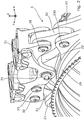
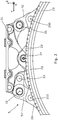
- the figures 2 and 3 represent the rear attachment 5 of an engine 2 of an aircraft.
- This fastener 5 comprises a beam 31, adapted to be secured to a mast 3 of the aircraft.
- This beam 31 comprises a plurality of yokes, a yoke being, in the present description, constituted by two substantially parallel flanks carrying at least one axis extending from one flank to the other. More specifically, the beam 31 comprises a yoke 32 carrying the fixing pins 320 and 330, oriented in the longitudinal direction, a yoke 34 carrying a fixing pin 340 oriented in the longitudinal direction, and a yoke 35, also called "first yoke In the present description, carrying a fixing pin 350 oriented in the longitudinal direction.
- the axis 350, carried by the first yoke 35, is connected to an axis 230, carried by a yoke 23 integral with the housing 20 of the engine 2.
- This yoke 23 is also called “second yoke” in the present description.
- This connection is made by a shackle 52, or rod, having two parallel holes, allowing the passage of two axes 350 and 230.
- the fixing pin 340 passes through a hole provided in a central fixing lug 22, integral with the casing 20 of the motor 2.
- the two attachment shafts 320 and 330 are connected to an attachment pin 210 carried by a clevis 21. - Even integral with the housing 20 of the engine 2. This connection is made by a shackle 51 comprising three parallel holes, allowing the passage of the three axes 320, 330 and 210.
- a shackle in the sense of the present description, is a substantially flat piece having several holes for connecting together several substantially parallel axes. going through these holes.
- the Figures 4a, 4b and 4c represent, in side view, the first yoke 35, integral with the beam 31, the second yoke 23, integral with the casing 20 of the engine 2, and the shackle 52.
- the fixing device does not comprise no washers.
- the second clevis 23 linked to the engine 2 can move slightly relative to the first clevis 35 secured to the mast 3.
- the shackle 52 is fixed to axes 350 and 230 by means of ball joints 521 and 522.
- this shackle 52 To prevent this shackle 52 from coming into contact with the sidewalls 311 and 312 of the yoke 35 which carries the axis 350, it is intended to place on the axis 350 two washers 61 and 62, arranged on either side of the shackle 52, and separating this shackle 52 from the flanks 311 and 312 of the yoke 35.
- the washer 61 separates the flank 311 from the shackle 52
- the washer 62 separates the flank 312 from the shackle 52.
- the presence of these washers limits the pivoting of the shackle 52 about the axis passing through the center of the ball joints 521 and 522, and consequently prevents the contact between the shackle 52 and the flanks 521 and 522 of the yoke 31.
- the washers 61 and 62 are wear parts formed in a material less hard than the shackle 52. They may for example be made of a metal such as copper or an alloy such as brass, when the shackle 52 is made of steel. In general, any material, in particular metal, having a hardness (measured with conventional methods) lower than the hardness of the material making up the shackle, can be used. Thus, the contact between these parts causes wear of the washers 61 and 62, without causing significant wear of the shackle 52.
- the washers 61 and 62 have no mechanical function of attachment of the motor, their wear does not affect not the security of the fixing device, and does not require their replacement as they fulfill their role of separation between the shackle 52 and the sides 311 and 312 of the yoke 31.
- the engine attachment device thus reduces the number of maintenance operations on the rear attachment.
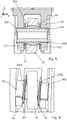
- the figure 5 shows the manner in which the washers 61 and 62 are mounted on the axis 350.
- the axis 350 is mounted in the holes of the sidewalls 311 and 312 of the yoke 35 by means of bushings, or bushes 351 and 352.
- Each of these rings, respectively 351 and 352 comprise a cylindrical portion surrounding the axis 350 and a flange, respectively 3510 and 3520, intended to bear against the internal face of the flank, respectively 311 and 312, of
- the washer 61 is interposed between the flange 3510 of the ring 351, and the ball 521.
- the washer 62 is interposed between the flange 3520 of the ring 352 and the flange 521.
- the flanges 3510 and 3520 thus separate the washers 61 and 62 from the flanks 311 and 312.
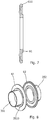
- the figure 7 represents the washer 61 in sectional view according to its diameter.
- the washer 61 has, near its outer edge which is preferably circular, a peripheral bead 610, circular, which is intended to come into contact with the shackle 52 and to be worn by this shackle.
- the thickness of this bead allows the washer 61 to withstand significant wear of its bead 610 before having to be replaced.
- the washer 61 shown is disk-shaped. However, it is possible, according to other embodiments that can be implemented by the skilled person, to use washers having different shapes. Those skilled in the art will choose for this purpose washers having shapes and dimensions allowing it to prevent contact between the shackle and the flanks of the yoke bearing the axis attached to the shackle.
- similar washers may also be arranged around the second axis 230, on either side of the shackle 52, to prevent contact between this shackle and the sides of the yoke 23. More generally, it may be advantageous to implement such washers at the connection of aircraft engine mounting shackles having two ball joints with axes carried by clevises, when the shackles comprise shapes that can come into contact with the flanks of the one or the other of the screeds.
Landscapes
- Engineering & Computer Science (AREA)
- Aviation & Aerospace Engineering (AREA)
- Pivots And Pivotal Connections (AREA)
- Snaps, Bayonet Connections, Set Pins, And Snap Rings (AREA)
- Vehicle Body Suspensions (AREA)
Description
- La présente invention concerne un dispositif de fixation d'un moteur d'aéronef. Elle concerne également un aéronef comprenant un tel dispositif de fixation.
- Dans de nombreux aéronefs destinés au transport de passagers, les moteurs de l'aéronef sont suspendus à un mât qui est lui-même fixé en-dessous de la voilure de l'aéronef.
- La
figure 1 représente schématiquement une liaison entre une aile 1 d'un aéronef et un moteur 2, constitué par un turboréacteur à double flux. Cette liaison est assurée par l'intermédiaire du mât 3 qui permet de transmettre à la structure de l'aéronef les efforts générés par le moteur 2 et permet également le cheminement des conduites de carburant, des systèmes électriques, hydrauliques et air entre le moteur 2 et l'aile 1 de l'aéronef. - Dans la description qui suit, l'avant et l'arrière sont définis relativement à une direction d'avancement F de l'aéronef. De plus, on appelle direction longitudinale X la direction de l'axe de rotation du moteur 2, direction transversale Y la direction s'étendant perpendiculairement à la direction longitudinale X, dans un plan horizontal, et direction horizontale Z la direction s'étendant perpendiculairement à la direction longitudinale X, dans un plan sensiblement vertical. Ces trois directions X, Y et Z sont orthogonales entre elles.
- La fixation du moteur 2 sur le mât 3 est réalisée par un dispositif de fixation comprenant une attache avant 4, une attache arrière 5, et des bielles de reprises d'effort 6. Ce dispositif de fixation supporte d'une part le poids du moteur 2 et d'autre part les efforts importants générés par le moteur 2, qui s'exercent dans des sens différents quand le moteur 2 propulse l'aéronef et quand le moteur 2, grâce à un système d'inversion de poussée, freine l'aéronef.
- Dans l'attache moteur arrière 5, la fixation du moteur 2 au mât 3 est, dans certains aéronef, assurée notamment par l'intermédiaire d'une manille, ou bielle, reliée, par l'intermédiaire de liaisons rotules, à deux axes sensiblement parallèles portés chacun par des chapes, l'un des axes étant solidarisé au mat 3 et l'autre axe étant solidarisé au moteur 2.
- En fonction des efforts exercés par le moteur 2, celui-ci peut se déplacer légèrement par rapport au mât 3. Les liaisons rotules connectant la manille aux deux axes permet ces déplacements sans endommager l'attache 5. Cependant, ces rotules permettent également à la manille de pivoter autour d'un axe passant le centre des deux rotules, jusqu'à des positions dans lesquelles les bords de la manille entrent en contact avec les flancs des chapes portant les axes.
- Un tel contact entre des pièces subissant des efforts et des vibrations très importants peut engendrer une usure prématurée de la manille et/ou des chapes, pouvant nécessiter leur remplacement à des intervalles rapprochés. Ce remplacement de pièces représente bien sur un coût important pour les exploitants de l'aéronef.
- Le document
EP1 982 915 représente un autre exemple de dispositif de fixation d'un moteur à un mât. Ledit document est considéré comme l'art antérieur le plus proche et décrit les caractéristiques du préambule de la revendication 1. La présente invention a pour objectif de remédier à cet inconvénient de l'art antérieur. - Plus précisément, un objectif de l'invention est de fournir un dispositif de fixation d'un moteur d'aéronef pour lequel les opérations de maintenance sont réduites.
- Un objectif particulier de l'invention est de fournir un tel dispositif de fixation d'un moteur d'aéronef dans lequel l'usure des pièces de fixation du moteur est réduite.
- Ces objectifs, ainsi que d'autres qui apparaitront plus clairement par la suite, sont atteints par un dispositif de fixation d'un moteur d'aéronef à un mât solidaire de la structure de l'aéronef, le dispositif de fixation comprenant :
- une poutre, apte à être solidarisée au mât, et comprenant une première chape qui comprend deux flancs reliés l'un à l'autre par un premier axe de fixation ;
- une seconde chape, solidaire du moteur, et comprenant deux flancs reliés l'un à l'autre par un second axe de fixation ;
- une manille connectée au premier axe par l'intermédiaire d'une première liaison rotule, et au second axe par l'intermédiaire d'une seconde liaison rotule ;
- La mise en place des rondelles entre la manille et les flancs permet d'éviter tout contact et tout frottement entre les flancs et la manille, ce qui évite l'usure de ces pièces les unes contre les autres.
- Préférentiellement, les rondelles sont constituées dans un matériau de dureté inférieure au matériau constituant la manille.
- De préférence, les rondelles présentent un bord externe circulaire.
- Avantageusement, ces rondelles présentent, à proximité de ce bord externe, un bourrelet circulaire.
- L'invention concerne également un aéronef, comprenant un moteur fixé à un mât de fixation solidaire de la structure de l'aéronef, par l'intermédiaire d'un dispositif de fixation tel que décrit ci-dessus.
- L'invention sera mieux comprise à la lecture de la description suivante d'un mode de réalisation préférentiel, donné à titre d'exemple illustratif et non limitatif, et accompagné des figures parmi lesquelles :
- la
figure 1 , qui a déjà été commentée, représente schématiquement la fixation d'un moteur d'aéronef sous la voilure de l'aéronef, selon l'art antérieur ; - la
figure 2 représente en perspective l'attache arrière d'un moteur d'aéronef ; - la
figure 3 représente en vue de face l'attache arrière de lafigure 2 ; - les
figures 4a à 4c , représentent, en vue de côté, l'attache de lafigure 2 , dans trois positions possibles en l'absence de rondelles selon un mode de réalisation de l'invention ; - la
figure 5 représente en vue de coupe l'assemblage d'une manille à une chape, dans l'attache arrière de lafigure 2 , équipée de rondelles selon un mode de réalisation de l'invention ; - la
figure 6 représente la manille, les douilles et les rondelles mis en oeuvre dans l'assemblage de lafigure 5 ; - la
figure 7 représente en vue de coupe une rondelle mise en oeuvre dans l'assemblage de lafigure 5 ; - la
figure 8 représente les douilles et les rondelles mises en oeuvre dans l'assemblage de lafigure 5 . - Les
figures 2 et3 représentent l'attache arrière 5 d'un moteur 2 d'un aéronef. Cette attache 5 comprend une poutre 31, apte à être solidarisée à un mât 3 de l'aéronef. Cette poutre 31 comprend plusieurs chapes, une chape étant, dans la présente description, constituée par deux flancs sensiblement parallèles portant au moins un axe s'étendant d'un flanc à l'autre. Plus précisément, la poutre 31 comporte une chape 32 portant les axes de fixation 320 et 330, orientés selon la direction longitudinale, une chape 34 portant un axe de fixation 340 orienté selon la direction longitudinale, et un chape 35, également appelée « première chape » dans la présente description, portant un axe de fixation 350 orienté selon la direction longitudinale. - L'axe 350, porté par la première chape 35, est connecté à un axe de 230, porté par une chape 23 solidaire du carter 20 du moteur 2. Cette chape 23 est également appelée « seconde chape » dans la présente description. Cette connexion est réalisée par une manille 52, ou bielle, présentant deux trous parallèles, permettant le passage de deux axes 350 et 230.
- L'axe de fixation 340 passe dans un trou prévu dans une patte de fixation centrale 22, solidaire du carter 20 du moteur 2. Les deux axes de fixation 320 et 330 sont connectés à un axe de fixation 210 porté par une chape 21, elle-même solidaire du carter 20 du moteur 2. Cette connexion est réalisée par une manille 51 comprenant trois trous parallèles, permettant le passage des trois axes 320, 330 et 210.
- Une manille, au sens de la présente description, est une pièce sensiblement plate présentant plusieurs trous pour connecter entre eux plusieurs axes sensiblement parallèles passant par ces trous. Une manille qui, comme la manille 52, comprend deux trous pour connecter deux axes parallèles, est équivalente à une bielle.
- Les
figures 4a, 4b et 4c représentent, en vue de côté, la première chape 35, solidaire de la poutre 31, la seconde chape 23, solidaire du carter 20 du moteur 2, et la manille 52. Dans la configuration représentée par ces figures, le dispositif de fixation ne comprend pas de rondelles. En fonction des efforts exercés par le moteur 2, la seconde chape 23 liée au moteur 2 peut se déplacer légèrement par rapport à la première chape 35 solidaire du mât 3. Pour permettre ces déplacements sans endommager les attaches moteur, la manille 52 est fixée aux axes 350 et 230 par l'intermédiaire de rotules 521 et 522. Ces rotules 521 et 522 permettent à la manille 52 de pivoter par rapport à sa position nominale représentée par lafigure 4a , autour d'un axe passant le centre des deux rotules, entre des positions extrêmes représentées par lesfigures 4b et 4c . Dans ces positions extrêmes, les bords de la manille 52 entrent en contact avec les flancs de la première chape 35 ou de la seconde chape 23. - Pour éviter une usure prématurée de la manille 52 ou des flancs de la première chape 35 ou de la seconde chape 23, il est prévu, selon un mode de réalisation de l'invention, de placer des rondelles 61, 62, dans le dispositif de fixation, comme le montre notamment la
figure 5 . Lafigure 5 représente ainsi en vue de coupe l'assemblage de la manille 52 à la première chape 35. - Pour empêcher que cette manille 52 ne rentre en contact avec les flancs 311 et 312 de la chape 35 qui porte l'axe 350, il est prévu de placer sur l'axe 350 deux rondelles 61 et 62, disposées de part et d'autre de la manille 52, et séparant cette manille 52 des flancs 311 et 312 de la chape 35. Ainsi, la rondelle 61 sépare le flanc 311 de la manille 52, et la rondelle 62 sépare le flanc 312 de la manille 52. Comme le montre la
figure 6 , la présence de ces rondelles limite le pivotement de la manille 52 autour de l'axe passant par le centre des rotules 521 et 522, et empêche en conséquence le contact entre la manille 52 et les flancs 521 et 522 de la chape 31. - La manille 52 entrant en contact avec les rondelles 61 et 62, une usure peut apparaitre entre ces pièces. De préférence, les rondelles 61 et 62 sont des pièces d'usure formées dans un matériau moins dur que la manille 52. Elles peuvent par exemple être constituées dans un métal tel que le cuivre ou un alliage tel que le laiton, quand la manille 52 est fabriquée en acier. De façon générale, tout matériau, notamment métallique, présentant une dureté (mesurée avec des procédés conventionnels) inférieure à la dureté du matériau composant la manille, peut être utilisé. Ainsi, le contact entre ces pièces entraine une usure des rondelles 61 et 62, sans entrainer d'usure significative de la manille 52. Les rondelles 61 et 62 n'ayant pas de fonction mécanique d'attache du moteur, leur usure n'affecte pas la sécurité du dispositif de fixation, et n'impose pas leur remplacement tant qu'elles remplissent leur rôle de séparation entre la manille 52 et les flancs 311 et 312 de la chape 31.
- Le dispositif de fixation de moteur selon l'invention permet ainsi de réduire le nombre d'opérations de maintenance sur l'attache arrière. De plus, quand une maintenance est effectuée, il n'est nécessaire de changer que les rondelles 61 et 62, qui sont des pièces d'usure peu onéreuses, sans qu'il soit nécessaire de changer la chape 35 ou la manille 52.
- La
figure 5 montre la manière dont sont montées les rondelles 61 et 62 sur l'axe 350. Comme le montre cette figure, l'axe 350 est monté dans les trous des flancs 311 et 312 de la chape 35 par l'intermédiaire de douilles, ou bagues 351 et 352. Chacune de ces bagues, respectivement 351 et 352, comportent une portion cylindrique entourant l'axe 350 et une collerette, respectivement 3510 et 3520, destinée à venir en appui contre la face interne du flanc, respectivement 311 et 312, de la chape 35. Quand le dispositif de fixation du moteur est monté, la rondelle 61 est intercalée entre la collerette 3510 de la bague 351, et la rotule 521. De même, la rondelle 62 est intercalée entre la collerette 3520 de la bague 352 et la rotule 521. Les collerettes 3510 et 3520 séparent donc les rondelles 61 et 62 des flancs 311 et 312. - La
figure 7 représente la rondelle 61 en vue de coupe selon son diamètre. Comme le montre cette figure, la rondelle 61 présente, à proximité de son bord externe de qui est de préférence circulaire, un bourrelet périphérique 610, circulaire, qui est destiné à entrer en contact avec la manille 52 et à être usé par cette manille. L'épaisseur de ce bourrelet permet que la rondelle 61 puisse supporter une usure importante de son bourrelet 610 avant de devoir être remplacées. - La rondelle 61 représentée est en forme de disque. Il est cependant possible, selon d'autres modes de réalisation que peut mettre en oeuvre l'homme du métier, d'utiliser des rondelles présentant des formes différentes. L'homme du métier choisira pour cela des rondelles présentant des formes et des dimensions lui permettant d'empêcher le contact entre la manille et les flancs de la chape portant l'axe fixé à la manille.
- De façon avantageuse, des rondelles similaires peuvent également être disposées autour du second axe 230, de part et d'autre de la manille 52, pour empêcher le contact entre cette manille et les flancs de la chape 23. Plus généralement, il peut être avantageux de mettre en oeuvre de telles rondelles au niveau de la liaison de manilles de fixation de moteur d'aéronef comportant deux liaisons rotules avec des axes portés par des chapes, quand les manilles comportent des formes susceptibles de rentrer en contact avec les flancs de l'une ou l'autre des chapes.
Claims (5)
- Dispositif de fixation d'un moteur d'aéronef (2) à un mât (3) solidaire de la structure de l'aéronef, le dispositif de fixation comprenant :- une poutre (31), apte à être solidarisée audit mât (3), et comprenant une première chape (35) qui comprend deux flancs (311, 312) reliés l'un à l'autre par un premier axe de fixation (350) ;- une seconde chape (23), solidaire du moteur (2), et comprenant deux flancs reliés l'un à l'autre par un second axe de fixation (230) ;- une manille (52) connectée audit premier axe (350) par l'intermédiaire d'une première liaison rotule (521), et au second axe (230) par l'intermédiaire d'une seconde liaison rotule (522) ;le dispositif de fixation comprenant au moins une paire de rondelles (61, 62), disposées autour de l'un desdits axes (350, 230), de part et d'autre de ladite manille (52), et séparant ladite manille (52) des flancs (311, 312) de la chape portant ledit axe (350, 230),
caractérisé en ce que ladite manille (52) entre en contact avec lesdites rondelles (61, 62) dans ses positions extrêmes de rotation autour de l'axe passant par lesdites deux liaisons rotules (521, 522). - Dispositif de fixation selon la revendication 1, caractérisé en ce que lesdites rondelles (61, 62) sont constituées dans un matériau de dureté inférieure au matériau constituant ladite manille (52).
- Dispositif de fixation selon l'une quelconque des revendications précédentes, caractérisé en ce que chacune desdites rondelles présente un bord externe circulaire.
- Dispositif de fixation selon la revendication 3, caractérisé en ce que chacune desdites rondelles présente, à proximité dudit bord externe, un bourrelet périphérique.
- Aéronef, comprenant un moteur (2) fixé à un mât (3) de fixation solidaire de la structure de l'aéronef, par l'intermédiaire d'un dispositif de fixation selon l'une quelconque des revendications 1 à 4.
Applications Claiming Priority (1)
| Application Number | Priority Date | Filing Date | Title |
|---|---|---|---|
| FR1460416A FR3027875A1 (fr) | 2014-10-30 | 2014-10-30 | Dispositif de fixation d'un moteur d'aeronef, et aeronef correspondant |
Publications (2)
| Publication Number | Publication Date |
|---|---|
| EP3015368A1 EP3015368A1 (fr) | 2016-05-04 |
| EP3015368B1 true EP3015368B1 (fr) | 2017-07-26 |
Family
ID=52273298
Family Applications (1)
| Application Number | Title | Priority Date | Filing Date |
|---|---|---|---|
| EP15189457.3A Not-in-force EP3015368B1 (fr) | 2014-10-30 | 2015-10-13 | Dispositif de fixation d'un moteur d'aéronef, et aéronef correspondant |
Country Status (4)
| Country | Link |
|---|---|
| US (1) | US9676489B2 (fr) |
| EP (1) | EP3015368B1 (fr) |
| CN (1) | CN105564658B (fr) |
| FR (1) | FR3027875A1 (fr) |
Cited By (1)
| Publication number | Priority date | Publication date | Assignee | Title |
|---|---|---|---|---|
| GB2640157A (en) * | 2024-04-04 | 2025-10-15 | Rolls Royce Deutschland Ltd & Co Kg | Joint assembly and linkage arrangement |
Families Citing this family (25)
| Publication number | Priority date | Publication date | Assignee | Title |
|---|---|---|---|---|
| CN110182373B (zh) * | 2015-01-07 | 2023-01-10 | 洛德公司 | 用于飞行器发动机安装架的轴承组件 |
| FR3040076B1 (fr) * | 2015-08-13 | 2017-08-11 | Airbus Operations Sas | Ensemble moteur pour aeronef comprenant une structure primaire de mat d'accrochage equipee d'une extension de caisson comprenant deux parties en forme globale d'arceau |
| US10351224B2 (en) * | 2015-09-23 | 2019-07-16 | The Boeing Company | External structure mounting system for use with an aircraft |
| US10570950B2 (en) | 2016-05-23 | 2020-02-25 | United Technologies Corporation | Spherical joint assembly with a spherical bearing between integral collars |
| US10598211B2 (en) * | 2016-05-23 | 2020-03-24 | United Technologies Corporation | Spherical bearing sleeve configured with one or more discrete collars |
| FR3061480B1 (fr) * | 2016-12-30 | 2019-05-31 | Airbus Operations | Ensemble moteur pour aeronef comprenant une attache moteur avant facilitant son montage |
| US10358227B2 (en) * | 2017-08-15 | 2019-07-23 | The Boeing Company | Sideload reaction bearing |
| US10926885B2 (en) * | 2018-01-17 | 2021-02-23 | Honeywell International Inc. | Hybrid motion mount system |
| GB2577540A (en) * | 2018-09-28 | 2020-04-01 | Airbus Operations Ltd | Joint for connecting aircraft structures |
| EP3663206B1 (fr) * | 2018-12-06 | 2023-09-06 | AIRBUS HELICOPTERS DEUTSCHLAND GmbH | Attache pour la suspension d'un moteur d'aéronef |
| FR3089954B1 (fr) * | 2018-12-12 | 2021-01-08 | Airbus Operations Sas | Ensemble de motorisation pour un aeronef comprenant un support de charge |
| FR3093704B1 (fr) | 2019-03-11 | 2021-06-11 | Airbus Operations Sas | Attache moteur arrière d’un ensemble propulsif d’aéronef |
| FR3093995A1 (fr) * | 2019-03-18 | 2020-09-25 | Airbus Operations (S.A.S.) | Attache moteur arrière d’un aéronef présentant un encombrement réduit en largeur et aéronef comprenant au moins une telle attache moteur arrière |
| FR3094347A1 (fr) * | 2019-03-25 | 2020-10-02 | Airbus Operations (S.A.S.) | Attache moteur arrière d’un aéronef présentant des manilles en deux parties et aéronef comprenant au moins une telle attache moteur arrière |
| FR3094346A1 (fr) * | 2019-03-26 | 2020-10-02 | Airbus Operations | Ensemble pour un aeronef, l’ensemble comportant un mat, une attache moteur et un systeme de fixation entre le mat et l’attache moteur |
| FR3096351B1 (fr) * | 2019-05-22 | 2021-06-11 | Airbus Operations Sas | Systeme d’attache moteur arriere pour un moteur d’aeronef comportant une poutre realisee en trois parties |
| FR3097205B1 (fr) * | 2019-06-17 | 2022-01-14 | Airbus Operations Sas | Attache moteur pour un moteur d’un aeronef comportant une chape, une bielle et une piece d’interface entre la chape et la bielle |
| FR3098194B1 (fr) * | 2019-07-01 | 2021-07-16 | Airbus Operations Sas | Attache moteur pour un moteur d’un aeronef comportant une bielle et un systeme de maintien de la bielle |
| US11479104B2 (en) | 2019-07-24 | 2022-10-25 | Honeywell International Inc. | System and method for gas turbine engine mount with seal |
| FR3102150B1 (fr) * | 2019-10-17 | 2021-10-29 | Airbus Operations Sas | Attache moteur pour un moteur d’aeronef comportant une bielle et un systeme de maintien de la bielle |
| FR3108096B1 (fr) * | 2020-03-10 | 2023-02-10 | Airbus Operations Sas | Attache moteur pour un moteur d’un aeronef comportant une chape, une bielle et une piece d’usure entre la chape et la bielle |
| FR3114129B1 (fr) * | 2020-09-14 | 2022-08-05 | Safran Aircraft Engines | Ensemble comportant une turbomachine d’aeronef et son pylone d’accrochage |
| FR3123888B1 (fr) * | 2021-06-09 | 2025-07-11 | Airbus Operations Sas | Aéronef comprenant au moins une turbomachine orientée approximativement parallèlement à un longeron d’une aile |
| FR3124164A1 (fr) * | 2021-06-30 | 2022-12-23 | Airbus Operations | Manille de fixation d’un moteur d’aeronef comprenant un couple de revetements antifriction encapsules, et aeronef comprenant une telle manille. |
| FR3154467B1 (fr) * | 2023-10-24 | 2025-09-12 | Safran Aircraft Engines | Ensemble de liaison |
Family Cites Families (8)
| Publication number | Priority date | Publication date | Assignee | Title |
|---|---|---|---|---|
| US3831888A (en) * | 1972-07-27 | 1974-08-27 | Mc Donnell Douglas Corp | Aircraft engine suspension system |
| US6669393B2 (en) * | 2001-10-10 | 2003-12-30 | General Electric Co. | Connector assembly for gas turbine engines |
| FR2862611B1 (fr) * | 2003-11-25 | 2007-03-09 | Airbus France | Dispositif d'accrochage d'un moteur sous une voilure d'aeronef |
| FR2887853B1 (fr) * | 2005-06-29 | 2007-08-17 | Airbus France Sas | Attache moteur pour aeronef destinee a etre interposee entre un moteur et un mat d'accrochage |
| FR2914907B1 (fr) * | 2007-04-16 | 2009-10-30 | Snecma Sa | Suspension souple avec peigne pour turbomoteur |
| FR2923459B1 (fr) * | 2007-11-09 | 2010-05-21 | Snecma | Moyen de blocage en rotation d'un axe supportant un organe de suspension de turbomoteur |
| FR2973339B1 (fr) * | 2011-03-29 | 2014-08-22 | Snecma | Dispositif de suspension d'une turbomachine a un avion |
| FR2975132B1 (fr) * | 2011-05-09 | 2015-06-26 | Snecma | Bielles de suspension du canal de flux froid d'un turboreacteur a rotules excentriques |
-
2014
- 2014-10-30 FR FR1460416A patent/FR3027875A1/fr not_active Withdrawn
-
2015
- 2015-10-13 EP EP15189457.3A patent/EP3015368B1/fr not_active Not-in-force
- 2015-10-22 US US14/920,207 patent/US9676489B2/en not_active Expired - Fee Related
- 2015-10-29 CN CN201510718857.1A patent/CN105564658B/zh not_active Expired - Fee Related
Non-Patent Citations (1)
| Title |
|---|
| None * |
Cited By (1)
| Publication number | Priority date | Publication date | Assignee | Title |
|---|---|---|---|---|
| GB2640157A (en) * | 2024-04-04 | 2025-10-15 | Rolls Royce Deutschland Ltd & Co Kg | Joint assembly and linkage arrangement |
Also Published As
| Publication number | Publication date |
|---|---|
| US20160122029A1 (en) | 2016-05-05 |
| CN105564658A (zh) | 2016-05-11 |
| EP3015368A1 (fr) | 2016-05-04 |
| CN105564658B (zh) | 2019-05-31 |
| FR3027875A1 (fr) | 2016-05-06 |
| US9676489B2 (en) | 2017-06-13 |
Similar Documents
| Publication | Publication Date | Title |
|---|---|---|
| EP3015368A1 (fr) | Dispositif de fixation d'un moteur d'aéronef, et aéronef correspondant | |
| EP0934877B1 (fr) | Dispositif d'accrochage d'un moteur d'aéronef | |
| EP2139768B1 (fr) | Mat d'accrochage de moteur pour aeronef disposant d'une attache moteur arriere pourvue d'un ecrou a barillet | |
| EP1858758B1 (fr) | Attache moteur d'un systeme de montage interpose entre un mat d'accrochage et un moteur d'aeronef | |
| EP2426051B1 (fr) | Mât d'accrochage de turboréacteur pour aéronef comprenant des attaches voilure avant alignees | |
| EP1231138A1 (fr) | Dispositif d'accrochage d'un moteur sur un aéronef | |
| EP3194272B1 (fr) | Procede et dispositif de montage d'un moteur sur un pylone d'aeronef | |
| CA2623999A1 (fr) | Attache arriere d'un moteur d'aeronef a deux manilles | |
| EP3750811A1 (fr) | Systeme d'attache moteur avant pour un moteur d'aeronef comportant une fixation directe entre le mat reacteur et le moteur | |
| EP4484297B1 (fr) | Système d'attache moteur avant pour un moteur d'aéronef qui comporte une structure compacte | |
| EP3486174B1 (fr) | Attache moteur arriere pour un moteur d'aeronef | |
| EP4484298B1 (fr) | Système d attache moteur avant pour un moteur d aéronef qui comporte une structure compacte | |
| FR2652859A1 (fr) | Dispositif d'amortissement des vibrations de volet de tuyere et joint pivotant pour l'amortissement de vibrations. | |
| EP1940682B1 (fr) | Ensemble moteur pour aeronef | |
| FR3058986A1 (fr) | Attache arriere d'un moteur d'aeronef comportant des temoins de rupture | |
| EP1571082A1 (fr) | Système de montage interposé entre un moteur d'aéronef et une structure rigide d'un mât d'accrochage fixé sous une voilure de cet aéronef | |
| FR2950118A1 (fr) | Palier glissant rotule et dispositif de liaison associe d'un mat d'accrochage de turbomoteur sous une voilure d'aeronef comportant un tel palier. | |
| EP3728039B1 (fr) | Dispositif de suspension | |
| EP3107748B1 (fr) | Dispositif de suspension d'un groupe motopropulseur de véhicule automobile | |
| FR3096350A1 (fr) | Systeme d’attache moteur avant pour un moteur d’aeronef comportant une poutre realisee en trois parties | |
| FR3043751A1 (fr) | Organe de support et de guidage d'une turbomachine d'aeronef pendant sa pose ou sa depose | |
| FR2965867A1 (fr) | Bielle structurale adaptee a filtrer des vibrations longitudinales | |
| FR3051834A1 (fr) | Ferrure de manutention a mors mobiles pour un carter de turbomachine | |
| EP3680176A1 (fr) | Attache-moteur d'aéronef comprenant au moins un système d'immobilisation en translation d'un pion de cisaillement comportant une plaque d'obturation, procédé de montage de ladite attache-moteur et aéronef comprenant ladite attache-moteur | |
| FR3098499A1 (fr) | Outillage pour deposer/reposer une turbomachine d’un mat d’un aeronef |
Legal Events
| Date | Code | Title | Description |
|---|---|---|---|
| PUAI | Public reference made under article 153(3) epc to a published international application that has entered the european phase |
Free format text: ORIGINAL CODE: 0009012 |
|
| AK | Designated contracting states |
Kind code of ref document: A1 Designated state(s): AL AT BE BG CH CY CZ DE DK EE ES FI FR GB GR HR HU IE IS IT LI LT LU LV MC MK MT NL NO PL PT RO RS SE SI SK SM TR |
|
| AX | Request for extension of the european patent |
Extension state: BA ME |
|
| 17P | Request for examination filed |
Effective date: 20161104 |
|
| RBV | Designated contracting states (corrected) |
Designated state(s): AL AT BE BG CH CY CZ DE DK EE ES FI FR GB GR HR HU IE IS IT LI LT LU LV MC MK MT NL NO PL PT RO RS SE SI SK SM TR |
|
| GRAP | Despatch of communication of intention to grant a patent |
Free format text: ORIGINAL CODE: EPIDOSNIGR1 |
|
| RIC1 | Information provided on ipc code assigned before grant |
Ipc: B64D 27/26 20060101AFI20170321BHEP |
|
| INTG | Intention to grant announced |
Effective date: 20170426 |
|
| GRAS | Grant fee paid |
Free format text: ORIGINAL CODE: EPIDOSNIGR3 |
|
| GRAA | (expected) grant |
Free format text: ORIGINAL CODE: 0009210 |
|
| AK | Designated contracting states |
Kind code of ref document: B1 Designated state(s): AL AT BE BG CH CY CZ DE DK EE ES FI FR GB GR HR HU IE IS IT LI LT LU LV MC MK MT NL NO PL PT RO RS SE SI SK SM TR |
|
| REG | Reference to a national code |
Ref country code: GB Ref legal event code: FG4D Free format text: NOT ENGLISH |
|
| REG | Reference to a national code |
Ref country code: CH Ref legal event code: EP |
|
| REG | Reference to a national code |
Ref country code: AT Ref legal event code: REF Ref document number: 912123 Country of ref document: AT Kind code of ref document: T Effective date: 20170815 |
|
| REG | Reference to a national code |
Ref country code: IE Ref legal event code: FG4D Free format text: LANGUAGE OF EP DOCUMENT: FRENCH |
|
| REG | Reference to a national code |
Ref country code: DE Ref legal event code: R096 Ref document number: 602015003737 Country of ref document: DE |
|
| REG | Reference to a national code |
Ref country code: FR Ref legal event code: PLFP Year of fee payment: 3 |
|
| REG | Reference to a national code |
Ref country code: NL Ref legal event code: MP Effective date: 20170726 |
|
| REG | Reference to a national code |
Ref country code: LT Ref legal event code: MG4D |
|
| REG | Reference to a national code |
Ref country code: AT Ref legal event code: MK05 Ref document number: 912123 Country of ref document: AT Kind code of ref document: T Effective date: 20170726 |
|
| PG25 | Lapsed in a contracting state [announced via postgrant information from national office to epo] |
Ref country code: HR Free format text: LAPSE BECAUSE OF FAILURE TO SUBMIT A TRANSLATION OF THE DESCRIPTION OR TO PAY THE FEE WITHIN THE PRESCRIBED TIME-LIMIT Effective date: 20170726 Ref country code: LT Free format text: LAPSE BECAUSE OF FAILURE TO SUBMIT A TRANSLATION OF THE DESCRIPTION OR TO PAY THE FEE WITHIN THE PRESCRIBED TIME-LIMIT Effective date: 20170726 Ref country code: NL Free format text: LAPSE BECAUSE OF FAILURE TO SUBMIT A TRANSLATION OF THE DESCRIPTION OR TO PAY THE FEE WITHIN THE PRESCRIBED TIME-LIMIT Effective date: 20170726 Ref country code: FI Free format text: LAPSE BECAUSE OF FAILURE TO SUBMIT A TRANSLATION OF THE DESCRIPTION OR TO PAY THE FEE WITHIN THE PRESCRIBED TIME-LIMIT Effective date: 20170726 Ref country code: AT Free format text: LAPSE BECAUSE OF FAILURE TO SUBMIT A TRANSLATION OF THE DESCRIPTION OR TO PAY THE FEE WITHIN THE PRESCRIBED TIME-LIMIT Effective date: 20170726 Ref country code: SE Free format text: LAPSE BECAUSE OF FAILURE TO SUBMIT A TRANSLATION OF THE DESCRIPTION OR TO PAY THE FEE WITHIN THE PRESCRIBED TIME-LIMIT Effective date: 20170726 Ref country code: NO Free format text: LAPSE BECAUSE OF FAILURE TO SUBMIT A TRANSLATION OF THE DESCRIPTION OR TO PAY THE FEE WITHIN THE PRESCRIBED TIME-LIMIT Effective date: 20171026 |
|
| PG25 | Lapsed in a contracting state [announced via postgrant information from national office to epo] |
Ref country code: IS Free format text: LAPSE BECAUSE OF FAILURE TO SUBMIT A TRANSLATION OF THE DESCRIPTION OR TO PAY THE FEE WITHIN THE PRESCRIBED TIME-LIMIT Effective date: 20171126 Ref country code: ES Free format text: LAPSE BECAUSE OF FAILURE TO SUBMIT A TRANSLATION OF THE DESCRIPTION OR TO PAY THE FEE WITHIN THE PRESCRIBED TIME-LIMIT Effective date: 20170726 Ref country code: PL Free format text: LAPSE BECAUSE OF FAILURE TO SUBMIT A TRANSLATION OF THE DESCRIPTION OR TO PAY THE FEE WITHIN THE PRESCRIBED TIME-LIMIT Effective date: 20170726 Ref country code: GR Free format text: LAPSE BECAUSE OF FAILURE TO SUBMIT A TRANSLATION OF THE DESCRIPTION OR TO PAY THE FEE WITHIN THE PRESCRIBED TIME-LIMIT Effective date: 20171027 Ref country code: RS Free format text: LAPSE BECAUSE OF FAILURE TO SUBMIT A TRANSLATION OF THE DESCRIPTION OR TO PAY THE FEE WITHIN THE PRESCRIBED TIME-LIMIT Effective date: 20170726 Ref country code: LV Free format text: LAPSE BECAUSE OF FAILURE TO SUBMIT A TRANSLATION OF THE DESCRIPTION OR TO PAY THE FEE WITHIN THE PRESCRIBED TIME-LIMIT Effective date: 20170726 Ref country code: BG Free format text: LAPSE BECAUSE OF FAILURE TO SUBMIT A TRANSLATION OF THE DESCRIPTION OR TO PAY THE FEE WITHIN THE PRESCRIBED TIME-LIMIT Effective date: 20171026 |
|
| PG25 | Lapsed in a contracting state [announced via postgrant information from national office to epo] |
Ref country code: RO Free format text: LAPSE BECAUSE OF FAILURE TO SUBMIT A TRANSLATION OF THE DESCRIPTION OR TO PAY THE FEE WITHIN THE PRESCRIBED TIME-LIMIT Effective date: 20170726 Ref country code: DK Free format text: LAPSE BECAUSE OF FAILURE TO SUBMIT A TRANSLATION OF THE DESCRIPTION OR TO PAY THE FEE WITHIN THE PRESCRIBED TIME-LIMIT Effective date: 20170726 Ref country code: CZ Free format text: LAPSE BECAUSE OF FAILURE TO SUBMIT A TRANSLATION OF THE DESCRIPTION OR TO PAY THE FEE WITHIN THE PRESCRIBED TIME-LIMIT Effective date: 20170726 |
|
| REG | Reference to a national code |
Ref country code: DE Ref legal event code: R097 Ref document number: 602015003737 Country of ref document: DE |
|
| PG25 | Lapsed in a contracting state [announced via postgrant information from national office to epo] |
Ref country code: SM Free format text: LAPSE BECAUSE OF FAILURE TO SUBMIT A TRANSLATION OF THE DESCRIPTION OR TO PAY THE FEE WITHIN THE PRESCRIBED TIME-LIMIT Effective date: 20170726 Ref country code: MC Free format text: LAPSE BECAUSE OF FAILURE TO SUBMIT A TRANSLATION OF THE DESCRIPTION OR TO PAY THE FEE WITHIN THE PRESCRIBED TIME-LIMIT Effective date: 20170726 Ref country code: IT Free format text: LAPSE BECAUSE OF FAILURE TO SUBMIT A TRANSLATION OF THE DESCRIPTION OR TO PAY THE FEE WITHIN THE PRESCRIBED TIME-LIMIT Effective date: 20170726 Ref country code: EE Free format text: LAPSE BECAUSE OF FAILURE TO SUBMIT A TRANSLATION OF THE DESCRIPTION OR TO PAY THE FEE WITHIN THE PRESCRIBED TIME-LIMIT Effective date: 20170726 Ref country code: SK Free format text: LAPSE BECAUSE OF FAILURE TO SUBMIT A TRANSLATION OF THE DESCRIPTION OR TO PAY THE FEE WITHIN THE PRESCRIBED TIME-LIMIT Effective date: 20170726 |
|
| PLBE | No opposition filed within time limit |
Free format text: ORIGINAL CODE: 0009261 |
|
| STAA | Information on the status of an ep patent application or granted ep patent |
Free format text: STATUS: NO OPPOSITION FILED WITHIN TIME LIMIT |
|
| 26N | No opposition filed |
Effective date: 20180430 |
|
| REG | Reference to a national code |
Ref country code: IE Ref legal event code: MM4A |
|
| PG25 | Lapsed in a contracting state [announced via postgrant information from national office to epo] |
Ref country code: LU Free format text: LAPSE BECAUSE OF NON-PAYMENT OF DUE FEES Effective date: 20171013 |
|
| REG | Reference to a national code |
Ref country code: BE Ref legal event code: MM Effective date: 20171031 |
|
| PG25 | Lapsed in a contracting state [announced via postgrant information from national office to epo] |
Ref country code: BE Free format text: LAPSE BECAUSE OF NON-PAYMENT OF DUE FEES Effective date: 20171031 Ref country code: SI Free format text: LAPSE BECAUSE OF FAILURE TO SUBMIT A TRANSLATION OF THE DESCRIPTION OR TO PAY THE FEE WITHIN THE PRESCRIBED TIME-LIMIT Effective date: 20170726 |
|
| PG25 | Lapsed in a contracting state [announced via postgrant information from national office to epo] |
Ref country code: MT Free format text: LAPSE BECAUSE OF FAILURE TO SUBMIT A TRANSLATION OF THE DESCRIPTION OR TO PAY THE FEE WITHIN THE PRESCRIBED TIME-LIMIT Effective date: 20170726 |
|
| REG | Reference to a national code |
Ref country code: FR Ref legal event code: PLFP Year of fee payment: 4 |
|
| PG25 | Lapsed in a contracting state [announced via postgrant information from national office to epo] |
Ref country code: IE Free format text: LAPSE BECAUSE OF NON-PAYMENT OF DUE FEES Effective date: 20171013 |
|
| REG | Reference to a national code |
Ref country code: CH Ref legal event code: PL |
|
| PG25 | Lapsed in a contracting state [announced via postgrant information from national office to epo] |
Ref country code: HU Free format text: LAPSE BECAUSE OF FAILURE TO SUBMIT A TRANSLATION OF THE DESCRIPTION OR TO PAY THE FEE WITHIN THE PRESCRIBED TIME-LIMIT; INVALID AB INITIO Effective date: 20151013 |
|
| PG25 | Lapsed in a contracting state [announced via postgrant information from national office to epo] |
Ref country code: CH Free format text: LAPSE BECAUSE OF NON-PAYMENT OF DUE FEES Effective date: 20181031 Ref country code: LI Free format text: LAPSE BECAUSE OF NON-PAYMENT OF DUE FEES Effective date: 20181031 |
|
| PG25 | Lapsed in a contracting state [announced via postgrant information from national office to epo] |
Ref country code: CY Free format text: LAPSE BECAUSE OF FAILURE TO SUBMIT A TRANSLATION OF THE DESCRIPTION OR TO PAY THE FEE WITHIN THE PRESCRIBED TIME-LIMIT Effective date: 20170726 |
|
| PG25 | Lapsed in a contracting state [announced via postgrant information from national office to epo] |
Ref country code: MK Free format text: LAPSE BECAUSE OF FAILURE TO SUBMIT A TRANSLATION OF THE DESCRIPTION OR TO PAY THE FEE WITHIN THE PRESCRIBED TIME-LIMIT Effective date: 20170726 |
|
| PG25 | Lapsed in a contracting state [announced via postgrant information from national office to epo] |
Ref country code: TR Free format text: LAPSE BECAUSE OF FAILURE TO SUBMIT A TRANSLATION OF THE DESCRIPTION OR TO PAY THE FEE WITHIN THE PRESCRIBED TIME-LIMIT Effective date: 20170726 |
|
| PG25 | Lapsed in a contracting state [announced via postgrant information from national office to epo] |
Ref country code: PT Free format text: LAPSE BECAUSE OF FAILURE TO SUBMIT A TRANSLATION OF THE DESCRIPTION OR TO PAY THE FEE WITHIN THE PRESCRIBED TIME-LIMIT Effective date: 20170726 |
|
| PG25 | Lapsed in a contracting state [announced via postgrant information from national office to epo] |
Ref country code: AL Free format text: LAPSE BECAUSE OF FAILURE TO SUBMIT A TRANSLATION OF THE DESCRIPTION OR TO PAY THE FEE WITHIN THE PRESCRIBED TIME-LIMIT Effective date: 20170726 |
|
| PGFP | Annual fee paid to national office [announced via postgrant information from national office to epo] |
Ref country code: DE Payment date: 20211020 Year of fee payment: 7 Ref country code: GB Payment date: 20211022 Year of fee payment: 7 |
|
| PGFP | Annual fee paid to national office [announced via postgrant information from national office to epo] |
Ref country code: FR Payment date: 20211022 Year of fee payment: 7 |
|
| REG | Reference to a national code |
Ref country code: DE Ref legal event code: R119 Ref document number: 602015003737 Country of ref document: DE |
|
| GBPC | Gb: european patent ceased through non-payment of renewal fee |
Effective date: 20221013 |
|
| PG25 | Lapsed in a contracting state [announced via postgrant information from national office to epo] |
Ref country code: FR Free format text: LAPSE BECAUSE OF NON-PAYMENT OF DUE FEES Effective date: 20221031 Ref country code: DE Free format text: LAPSE BECAUSE OF NON-PAYMENT OF DUE FEES Effective date: 20230503 |
|
| PG25 | Lapsed in a contracting state [announced via postgrant information from national office to epo] |
Ref country code: GB Free format text: LAPSE BECAUSE OF NON-PAYMENT OF DUE FEES Effective date: 20221013 |