EP3015359B1 - Device for fixing and making electrical contact between a cladding element of an aircraft and a support structure - Google Patents
Device for fixing and making electrical contact between a cladding element of an aircraft and a support structure Download PDFInfo
- Publication number
- EP3015359B1 EP3015359B1 EP14191356.6A EP14191356A EP3015359B1 EP 3015359 B1 EP3015359 B1 EP 3015359B1 EP 14191356 A EP14191356 A EP 14191356A EP 3015359 B1 EP3015359 B1 EP 3015359B1
- Authority
- EP
- European Patent Office
- Prior art keywords
- contacts
- cladding element
- aircraft
- supporting structure
- cladding
- Prior art date
- Legal status (The legal status is an assumption and is not a legal conclusion. Google has not performed a legal analysis and makes no representation as to the accuracy of the status listed.)
- Active
Links
- 238000005253 cladding Methods 0.000 title claims description 67
- 230000000295 complement effect Effects 0.000 description 6
- 230000015572 biosynthetic process Effects 0.000 description 4
- 238000009434 installation Methods 0.000 description 4
- 230000008901 benefit Effects 0.000 description 3
- 238000011161 development Methods 0.000 description 3
- 230000018109 developmental process Effects 0.000 description 3
- 238000005304 joining Methods 0.000 description 3
- 238000010276 construction Methods 0.000 description 2
- 238000004519 manufacturing process Methods 0.000 description 2
- 238000000034 method Methods 0.000 description 2
- 238000005476 soldering Methods 0.000 description 2
- 230000009471 action Effects 0.000 description 1
- 238000004026 adhesive bonding Methods 0.000 description 1
- 230000005540 biological transmission Effects 0.000 description 1
- 230000001419 dependent effect Effects 0.000 description 1
- 238000009795 derivation Methods 0.000 description 1
- 238000009826 distribution Methods 0.000 description 1
- 230000000694 effects Effects 0.000 description 1
- 239000000463 material Substances 0.000 description 1
- 230000008569 process Effects 0.000 description 1
- 230000002787 reinforcement Effects 0.000 description 1
- 239000003351 stiffener Substances 0.000 description 1
- 230000008719 thickening Effects 0.000 description 1
Images


Classifications
-
- H—ELECTRICITY
- H01—ELECTRIC ELEMENTS
- H01R—ELECTRICALLY-CONDUCTIVE CONNECTIONS; STRUCTURAL ASSOCIATIONS OF A PLURALITY OF MUTUALLY-INSULATED ELECTRICAL CONNECTING ELEMENTS; COUPLING DEVICES; CURRENT COLLECTORS
- H01R13/00—Details of coupling devices of the kinds covered by groups H01R12/70 or H01R24/00 - H01R33/00
- H01R13/73—Means for mounting coupling parts to apparatus or structures, e.g. to a wall
-
- B—PERFORMING OPERATIONS; TRANSPORTING
- B64—AIRCRAFT; AVIATION; COSMONAUTICS
- B64C—AEROPLANES; HELICOPTERS
- B64C1/00—Fuselages; Constructional features common to fuselages, wings, stabilising surfaces or the like
- B64C1/06—Frames; Stringers; Longerons ; Fuselage sections
- B64C1/066—Interior liners
-
- B—PERFORMING OPERATIONS; TRANSPORTING
- B64—AIRCRAFT; AVIATION; COSMONAUTICS
- B64F—GROUND OR AIRCRAFT-CARRIER-DECK INSTALLATIONS SPECIALLY ADAPTED FOR USE IN CONNECTION WITH AIRCRAFT; DESIGNING, MANUFACTURING, ASSEMBLING, CLEANING, MAINTAINING OR REPAIRING AIRCRAFT, NOT OTHERWISE PROVIDED FOR; HANDLING, TRANSPORTING, TESTING OR INSPECTING AIRCRAFT COMPONENTS, NOT OTHERWISE PROVIDED FOR
- B64F5/00—Designing, manufacturing, assembling, cleaning, maintaining or repairing aircraft, not otherwise provided for; Handling, transporting, testing or inspecting aircraft components, not otherwise provided for
- B64F5/10—Manufacturing or assembling aircraft, e.g. jigs therefor
-
- B—PERFORMING OPERATIONS; TRANSPORTING
- B64—AIRCRAFT; AVIATION; COSMONAUTICS
- B64D—EQUIPMENT FOR FITTING IN OR TO AIRCRAFT; FLIGHT SUITS; PARACHUTES; ARRANGEMENTS OR MOUNTING OF POWER PLANTS OR PROPULSION TRANSMISSIONS IN AIRCRAFT
- B64D2221/00—Electric power distribution systems onboard aircraft
-
- H—ELECTRICITY
- H01—ELECTRIC ELEMENTS
- H01R—ELECTRICALLY-CONDUCTIVE CONNECTIONS; STRUCTURAL ASSOCIATIONS OF A PLURALITY OF MUTUALLY-INSULATED ELECTRICAL CONNECTING ELEMENTS; COUPLING DEVICES; CURRENT COLLECTORS
- H01R13/00—Details of coupling devices of the kinds covered by groups H01R12/70 or H01R24/00 - H01R33/00
- H01R13/02—Contact members
- H01R13/26—Pin or blade contacts for sliding co-operation on one side only
-
- H—ELECTRICITY
- H01—ELECTRIC ELEMENTS
- H01R—ELECTRICALLY-CONDUCTIVE CONNECTIONS; STRUCTURAL ASSOCIATIONS OF A PLURALITY OF MUTUALLY-INSULATED ELECTRICAL CONNECTING ELEMENTS; COUPLING DEVICES; CURRENT COLLECTORS
- H01R13/00—Details of coupling devices of the kinds covered by groups H01R12/70 or H01R24/00 - H01R33/00
- H01R13/62—Means for facilitating engagement or disengagement of coupling parts or for holding them in engagement
- H01R13/627—Snap or like fastening
- H01R13/6275—Latching arms not integral with the housing
-
- H—ELECTRICITY
- H01—ELECTRIC ELEMENTS
- H01R—ELECTRICALLY-CONDUCTIVE CONNECTIONS; STRUCTURAL ASSOCIATIONS OF A PLURALITY OF MUTUALLY-INSULATED ELECTRICAL CONNECTING ELEMENTS; COUPLING DEVICES; CURRENT COLLECTORS
- H01R2201/00—Connectors or connections adapted for particular applications
- H01R2201/26—Connectors or connections adapted for particular applications for vehicles
Definitions
- the invention relates to a device for fixing and electrically contacting a trim element of an aircraft to a support structure, which is fastened to a structure of the aircraft.
- the aircraft interior component system is characterized in that the aircraft interior component comprises at least one supply line section which is connected to a first connection device arranged on the aircraft interior component, the first connection device being set up to interact with a second connection device which is complementary to the first connection device in order to connect the supply line section To connect aircraft interior component with a corresponding aircraft-side supply line section.
- an interior component carrier system for use in the assembly of aircraft interior components in an aircraft, comprising a holding system with at least one holding element on which one first connecting device for connecting the holding element to a first aircraft interior component and a second connecting device are arranged, a holding device for attaching the holding element to an aircraft structure also being provided on the holding element.
- a holding system with at least one holding element on which one first connecting device for connecting the holding element to a first aircraft interior component and a second connecting device are arranged, a holding device for attaching the holding element to an aircraft structure also being provided on the holding element.
- the DE 10 2010 045 590 A1 describes a device for fastening an electrical device to a monument in an aircraft, which also ensures the establishment of an electrical connection between the electrical device and the monument.
- the EP 1 783 870 A1 describes a component with a carrier and a contact holder, which is movably mounted on a front of the carrier in a connecting direction.
- the WO 93/20601 A1 describes a lock with a mounting structure, an electrical feedthrough and a remote and / or locking device.
- the DE 19 730 323 A1 describes a construction for connecting connectors with a protrusion to an end connector while an oblique guide corresponding to the protrusion is formed on a connector part.
- the WO 99/62146 describes a contact element with electrical or fluidic contact means which can be displaced by an elastic means, in which the contact means is at least partially embedded and through whose surface the contact means are exposed.
- the interface between the aircraft-side supply network and the corresponding interior components is usually designed as a plug-in connection, which generates separate assembly work as part of a final assembly of the aircraft, the corresponding plug-in connections often being arranged with difficulty in areas of the interior components which are inaccessible.
- the object of the invention is therefore to provide a device which largely avoids the aspects mentioned in the prior art, i.e. discloses a device which, in addition to fastening an aircraft interior component to an aircraft-side support structure, enables a connection to an aircraft-side supply system which can be produced by the fastening, without to cause additional assembly effort.
- the object is with a device for fixing and electrical contacting of a trim element of an aircraft to a support structure, which is fastened to an aircraft structure, comprising a fixing device for releasably fixing the trim element to the support structure and a contacting device for providing a plurality of electrical contacts between the trim element-side cables and the support structure side Connection lines, solved in that the fixing device can be brought into a form-fitting engagement by means of a translational relative movement between the cladding element and the support structure, and the contacting device has at least two first contacts on the cladding element side and the same number of cooperating contacts on the supporting structure side, each of which contacts during the translational relative movement electrical contact can be brought, the first contacts with the lines on the cladding element side and the second contacts are connected to the lines on the supporting structure.
- a translational relative movement between the cladding element and the support structure results in a form-fitting engagement which secures the cladding element to the support structure.
- the positive engagement is designed to be detachable, so that the cladding element is easy to replace.
- An electrical connection between the first contacts on the lining element side and the second contacts on the supporting structure is established simultaneously with the form-fitting engagement via a contacting device, so that no additional assembly steps, such as, for example, making a plug connection in poorly accessible installation spaces, are necessary.
- the first contacts are connected to lines on the lining element side, which are advantageously forwarded to a location on the lining element side, for example for the electrical actuation of a blind.
- the second contacts are connected to lines which are connected to an aircraft-side electrical system via the supporting structure.
- the cladding element is designed as a cladding panel, in particular as a side cladding panel.
- a device according to the invention is particularly suitable for cladding an aircraft cabin on the inside, a different number of contacts being preferably arranged on the cladding element depending on the requirement situation. For example, it is conceivable that when using the device according to the invention for the interior lining of a passenger area of an aircraft cabin, more contacts have to be arranged than when using the device for the interior lining of a cargo area, since in a passenger area there is an increased demand for electrical leads for a variety of entertainment and comfort functions is to be expected.
- the support structure is designed as a carrier plate with an undercut vertical slot and on the cladding element an insertable fixing element is arranged with a head that can be brought into the undercut area.
- the fixing element is preferably designed such that, due to its head-like outer geometry, it can be inserted exactly into the undercut vertical slot by means of a vertical translational relative movement and forms a positive fit with the carrier plate when an assembly end position is reached.
- the contacting device comprises a plurality of elastically projecting first contacts which are arranged on the head and which are designed and set up in such a way that they interact with a number of second contacts which are fastened to a rear wall of the vertical slot.
- a resilient counterforce builds up in the form-fitting engagement of the cladding element with the carrier plate, as a result of which the cladding element-side first contacts are pressed onto the counter-force-like second contacts on the supporting structure side.
- the second contacts on the supporting structure are advantageously designed in the form of strips, which favors contact formation in the case of a vertical translational relative movement of the cladding element to the supporting structure in the translation direction.
- second contacts are arranged in longitudinal slots which are formed in a rear wall of the vertical slot.
- first contacts on the trim element side receive the installation space required in their complementary counterpart on the structure side, so that the trim element does not additionally project in the direction of the area of the aircraft to be covered.
- the cladding element-side first contacts are also advantageously formed like a bow, as a result of which their elastic effect and thus the counterforce when positive engagement of the first contacts on the second contacts is increased.
- first contacts on the lining element side in the first embodiment of the invention are connected to contact pins which extend into an inner region of the lining element and are detachably connected there to the lines on the lining element side. This creates a central electrical supply point on the cladding element, which can be flexibly accessed from any position of the cladding element by adapting the lines on the cladding element side.
- the contacting device has at least one non-conductive ramp element on the supporting structure side, on which a plurality of first contacts arranged next to one another are fastened, which are connected to the cables on the supporting structure side.
- the ramp element can be moved transversely to the direction of the translational movement against a restoring force, with the restoring force also, analogously to the first preferred embodiment of the invention, second contacts on the lining element side to the first contacts on the supporting structure side when the positive locking between the lining element and Support structure can be pressed.
- the restoring force is preferably generated by a restoring spring attached to the ramp element, as a result of which the restoring force can be set as required simply by varying the spring hardness.
- a return spring can be quickly replaced if the restoring force should decrease over the course of its useful life and no longer meet the specifications.
- the first contacts on the lining element side are further preferably arranged on a projection fastened to the lining element, which has an inclined surface, the surface of which is aligned parallel to the contact surface of the ramp element on the supporting structure side.
- the ramp element on the supporting structure side has a shaft, from the free end of which connecting pins protrude, which are connected to the first contacts.
- the shaft end and the connecting pins are detachably connected to one another via a plug, while the plug is in turn connected to the lines on the lining element side.
- the shaft and the plug are advantageously provided with a T-shaped inner profile, which only allows the plug and shaft to engage in one another in a certain position of the cladding element and support structure, which ensures intuitive installation and thus the risk of electrical incorrect contacting can be excluded .
- the plug has a locking hook on the outside, which is designed and set up such that it forms a positive and non-positive engagement when the shaft and plug interlock with a locking lug arranged on the shaft and designed to be complementary to the locking hook Final assembly state between the cladding element and the support structure is fixed.
- the embodiment not according to the invention is characterized in that the number of first contacts on the lining element side corresponds to the number of second contacts on the supporting structure side.
- the object is achieved with a second embodiment not according to the invention, which provides that the Contact element on the cladding element side has a number of first contacts running in the translation direction, which are designed to be elastically deformable in a bow-shaped manner and an equal number of second contacts extending in the translation direction are arranged on the support structure and are fastened in guide channels likewise oriented in the translation direction.
- the guide channels serve to guide the first contacts on the lining element during a translational relative movement between the lining element and the support structure on the second contacts and enable the production of an electrically conductive connection between the lining element and the support structure.
- the extension of the first and second contacts in the translation direction ensures that there is electrical contact between the cladding element and the support structure even before the final assembly position is reached.
- the bow-shaped first contacts are further advantageously fixed to the cladding element at one end and rest on the cladding element at the other end. In this way, manufacturing tolerances in the position of the guide channels on the structure side can be compensated for each other and thereby enable reliable contact properties.
- the fixing device is arranged between at least a first and a second contact and thereby enables a mirror-symmetrical alignment of the respective contact pairs to one another.
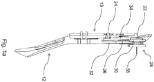
- FIG. 1a the basic mode of operation of an embodiment of a device according to the invention is shown in a vertical section.
- a support structure 12 is positively and non-positively joined to an aircraft structure 13 and serves as a flange material for receiving a fixing element 28, which is preferably designed and designed as a slider.
- the fixing element 28, which is designed as a slider Via a central guide arranged in the support structure 12, which is advantageously 11.5 mm wide, the fixing element 28, which is designed as a slider, is preferably has a diameter of 10 mm, is translationally guided in the vertical direction with a joining tolerance of 1.5 mm and is positively fixed in the support structure 12 when an assembly end position is reached.
- the aircraft structure 13 is a type of base plate which is fixed to an aircraft structure component, in particular to a frame, by means of riveted, screwed or welded connections.
- the fixing element is in turn on an in Fig. 1a Cladding element 10 not shown attached, which closes the aircraft structure 13 in the direction of an aircraft cabin as a cladding panel, preferably as a side cladding panel.
- a side cladding panel is, for example, in the publication DE 10 2011 009 815 A1 shown.
- a side cladding panel is, for example, in the publication DE 10 2011 009 815 A1 shown.
- the fixing element 28 further comprises a head 30, which is designed such that it can be brought into a form-fitting engagement with an undercut vertical slot 26 arranged on a rear wall 32 of the supporting structure 12 by translational relative movement of the supporting structure 12 to the fixing element 28, and in this way one produces a positive connection between the fixing element 28 and the support structure 12.
- the support structure 12 is thickened or reinforced in terms of construction at the material-transmitting joints, preferably by additional stiffening ribs. In the joined state there is also a gap between the in Fig.
- a plurality of first contacts 22 are arranged on the head 30 and thus on the side of the cladding element, which are advantageously designed to be elastically bow-shaped. With the first contacts 22 in the fixing element 28 further contact pins 36 are connected, which are in an inner region of the in Fig. 1a not shown Covering element 10 extend and there with in Fig. 1a Lines 18, which are likewise not visible, are advantageously connected by THT or SMT soldering methods, as a result of which a power supply is provided.
- the fixing element 28 is made electrical contact between the fixing element 28 and the in Fig. 1a Cladding element 10, not shown, by means of contact sockets with integrated contact pins arranged in a base of the fixing element 28, the contact sockets inserting the contact pins of the fixing element 28 into the socket in FIG Fig. 1a Guide trim element 10, not shown.
- the first contacts 22 further correspond to strip-like second contacts 24, which are arranged on the supporting structure side in the rear wall 32 of the vertical slot 26 and produce an electrical contact between the fixing element 28 and the supporting structure 12 when the supporting structure 12 translates relative to the fixing element 28.
- the second contacts 24 are fastened in longitudinal slots 34 on the rear wall 32 of the support structure 12 by screwing with the aid of set screws on the support structure side, which not only does not require any additional installation space and does not allow the trim element to protrude further in the direction of the aircraft cabin, but also the structural stiffeners or compensate for reinforcements at force-transmitting points of the support structure 12 in the aircraft cabin direction.
- the second contacts 24 on the rear side 32 of the supporting structure are included in Fig.
- Connection lines 20, which are also not visible on the supporting structure, are advantageously connected via cable lugs, alternatively via plugs, which in turn are connected to an aircraft electrical system and derive a power supply from this, which through the electrical contacting of the supporting structure 12 with the fixing element 28 to this or to the one with the Fixing element 28 connected cladding element is transferable.
- the second contacts 24 are protected against contact and short circuit by means of an insulating flap clamped onto the second contacts.
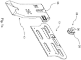
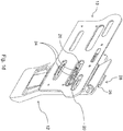
- Fig. 1b and Fig. 1c each show in an exploded view the components necessary for the functioning of the embodiment of a device according to the invention, while in Fig. 1d and Fig. 1e represent the explained concept of the embodiment of a device according to the invention in the assembled state.
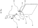
- Fig. 2a shows the principle of operation of an alternative device not according to the invention, again in a vertical section.
- a form-fitting connection between the cladding element 10 and the support structure 12 is achieved via a fixing element 28, on which a cladding element 10 is arranged, by translational relative movement of the fixing element 28 to a support structure 12 1.5 mm in the horizontal direction, which in turn on one in Fig. 2a
- Aircraft structure 13, not shown, is fastened in a positive and non-positive manner.
- all force-transmitting subcomponents on the support structure 12 are mechanically reinforced.
- the electrical contact between the support structure 12 and cladding element 10 takes place via at least one ramp element 38 which is arranged on the support structure side and is non-conductive.
- second contacts 24 are attached, which in turn are included in Fig. 2a not visible lines 20 connected to the structure.
- the ramp element 38 is preferably movable transversely to the translation direction against a restoring force which is generated by a restoring spring 40.
- the ramp element 38 preferably has a shaft 44, from the shaft of which protrude free end connecting pins 46, which cooperate in a positive engagement between the support structure 12 and fixing element 28 with cladding element-side contacts 22, which are advantageously secured by screwing on a protruding surface 42 equipped with a complementary element to the ramp element 38 and designed as a contact base, and one Make electrical contact, which is secured by the restoring force of the return spring 40.
- one end of the shaft 44 and the connecting pins 46 are detachably connected to one another via a plug 48, the plug 48 again being connected to in Fig. 2a not visible lines 18 lining element is connected.
- the shaft 44 and the connector 48 are provided with a T-shaped inner profile, which allows the connector 48 and the shaft 44 to engage in one another only in a specific position of the trim element 10 and the support structure 12.
- the plug 48 has a latching hook on an outer side, the latching hook forming a positive and non-positive engagement when the shaft 44 and plug 48 engage with a latching nose arranged on the shaft 44 and designed to be complementary to the latching hook, as a result of which the final assembly state is fixed between cladding element 10 and support structure 12.
- the first contacts 22 are also in in this device not according to the invention Fig. 2a Connections 18, not shown, on the lining element side.
- Fig. 2b and Fig. 2c again show an exploded view of the in Fig. 2a explained components of this device not according to the invention, while an assembled version in Fig. 2d and Fig. 2e is shown.
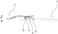
- FIG. 3a finally, the principle of operation of a second device not according to the invention is again in a vertical section in FIG Fig. 3b and Fig. 3c additionally shown in partial components of the second device not according to the invention in a rear or front view.
- this second one will not device according to the invention a positive contact between a support structure 12, which in turn on an in 3a to 3c Aircraft structure 13 which is not visible is fastened in a positive and non-positive manner, and a Fig. 3a likewise not visible fixing element 28, wherein a cladding element 10 is again arranged on the fixing element 28 and the positive connection is arranged on a rear side 32 of the support structure and in Fig. 3a and Fig.
- the covering element 10 comprises a number of first contacts 22 which extend in the translation direction and which are designed in the form of a bow in an elastic manner and correspond to an equal number of second contacts 24 which likewise extend in the translation direction and which again on the support structure 12 in guide channels 50 are attached and when the support structure 12 interlocks with the cladding element 10, produce an electrical contact between the support structure 12 and the cladding element 10.
- the guide channels 50 are formed by deliberately thickening the support structure 12 and, by gluing or jamming the second contacts 24, take them in recesses corresponding to the second contacts 24 after the second contacts 24 have previously been in a bore, each with the support structure side Connection plugs are advantageously integrally connected via SMT or THT soldering processes, alternatively positively and non-positively by means of crimp contacts, have been fixed in the guide channels 50.
- the first contacts 22 are in each case fixed at one end with the cladding element 10 and there with in Fig. 3a and Fig. 3c Lines 18, which are not visible on the lining element, are connected, while the first contacts 22 abut the lining element 10 like a floating bearing at the other end.
- the second contacts 24 corresponding to the first contacts 22 are accommodated on the supporting structure side in guide channels 50, which support the ends of the first contacts 22 which are fastened in the manner of a floating bearing during the positive locking formation by means of translational relative movement between the supporting structure 12 and the cladding element 10 Steer over the second contacts 24, the first contacts 22 being pressed against the second contacts 24 simultaneously by the elastic, bow-shaped configuration of the first contacts 22.
- the first contacts 22 on the lining element side are arranged on both sides of the fixing element 28 and thus enable symmetrical positioning and a symmetrical and thus easier to achieve form or frictional connection of the first contacts 22 to the second contacts 24.
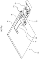
- Fig. 3d and Fig. 3e an assembled state of the second device, not according to the invention.
Description
Die Erfindung betrifft eine Vorrichtung zur Fixierung und elektrischen Kontaktierung eines Verkleidungselements eines Luftfahrzeugs an einer Tragstruktur, die an einer Struktur des Luftfahrzeugs befestigt ist.The invention relates to a device for fixing and electrically contacting a trim element of an aircraft to a support structure, which is fastened to a structure of the aircraft.
Gattungsbildende Vorrichtungen sind im Stand der Technik bekannt. Gegenwärtig ist es üblich, Interieurkomponenten eines Luftfahrzeugs, beispielsweise Verkleidungselemente, Lichtbänder, Gepäckablagen etc., einzeln an einer Tragstruktur zu befestigen, welche wiederum ihrerseits an einer Struktur des Luftfahrzeugs angeordnet ist. Häufig benötigen moderne Interieurkomponenten neben einem reinen Befestigungssystem zusätzlich Anschlüsse an eine Strom- und/oder Datenversorgungsleitung, welche typischerweise als Teil eines luftfahrzeugseitigen Bordnetzes ausgebildet ist. Aus der Druckschrift
Die
Die
Die
Die
Die
Überlicherweise ist die Schnittstelle zwischen dem flugzeugseitigen Versorgungsnetz und den entsprechenden Interieurkomponenten als Steckverbindung ausgeführt, die im Rahmen einer Endmontage des Flugzeugs gesonderten Montageaufwand erzeugt, wobei die entsprechenden Steckverbindungen häufig erschwerend in wenig zugänglichen Bereichen der Interieurkomponenten angeordnet sind.The interface between the aircraft-side supply network and the corresponding interior components is usually designed as a plug-in connection, which generates separate assembly work as part of a final assembly of the aircraft, the corresponding plug-in connections often being arranged with difficulty in areas of the interior components which are inaccessible.
Aufgabe der Erfindung ist es daher, eine Vorrichtung anzugeben, welche die im Stand der Technik genannten Gesichtspunkte weitestgehend vermeidet, also eine Vorrichtung offenbart, welche neben einer Befestigung einer Flugzeuginterieurkomponente an einer flugzeugseitigen Tragstruktur eine durch die Befestigung herstellbare Verbindung an ein flugzeugseitiges Versorgungssystem ermöglicht, ohne hierfür zusätzlichen Montageaufwand hervorzurufen.The object of the invention is therefore to provide a device which largely avoids the aspects mentioned in the prior art, i.e. discloses a device which, in addition to fastening an aircraft interior component to an aircraft-side support structure, enables a connection to an aircraft-side supply system which can be produced by the fastening, without to cause additional assembly effort.
Die Erfindung ergibt sich aus den Merkmalen der unabhängigen Ansprüche. Vorteilhafte Weiterbildungen und Ausgestaltungen sind Gegenstand der abhängigen Ansprüche.The invention results from the features of the independent claims. Advantageous further developments and refinements are the subject of the dependent claims.
Die Aufgabe ist mit einer Vorrichtung zur Fixierung und elektrischen Kontaktierung eines Verkleidungselements eines Luftfahrzeugs an einer Tragstruktur, die an einer Flugzeugstruktur befestigt ist, umfassend eine Fixiereinrichtung zur lösbaren Fixierung des Verkleidungselements an der Tragstruktur und eine Kontaktierungseinrichtung zur Bereitstellung mehrerer elektrischer Kontakte zwischen verkleidungselementseitigen Leitungen und tragstrukturseitigen Anschlussleitungen, dadurch gelöst, dass die Fixiereinrichtung mittels einer translatorischen Relativbewegung zwischen Verkleidungselement und Tragstruktur in einen formschlüssigen Eingriff bringbar ist, und die Kontaktierungseinrichtung mindestens zwei verkleidungselementseitige erste Kontakte und die gleiche Anzahl damit kooperierende tragstrukturseitige zweite Kontakte aufweist, die bei der translatorischen Relativbewegung jeweils miteinander in elektrischen Kontakt bringbar sind, wobei die ersten Kontakte mit den verkleidungselementseitigen Leitungen und die zweiten Kontakte mit den tragstrukturseitigen Leitungen verbunden sind. Erfindungsgemäß wird durch eine translatorische Relativbewegung zwischen dem Verkleidungselement und der Tragstruktur ein formschlüssiger Eingriff erwirkt, der das Verkleidungselement an der Tragstruktur befestigt. Der formschlüssige Eingriff ist lösbar gestaltet, so dass eine einfache Austauschbarkeit des Verkleidungselements gewährleistet ist. Über eine Kontaktierungseinrichtung wird gleichzeitig mit dem formschlüssigen Eingriff eine elektrische Verbindung zwischen verkleidungselementseitigen ersten Kontakten und tragstrukturseitigen zweiten Kontakten hergestellt, so dass keine zusätzlichen Montageschritte, wie beispielsweise gesondertes Herstellen von Steckverbindung in schlecht zugänglichen Bauräumen, notwendig sind. Die ersten Kontakte sind mit verkleidungselementseitigen Leitungen verbunden, welche vorteilhaft an einen verkleidungselementseitigen Bedarfsort, beispielsweise zur elektrischen Betätigung einer Jalousie, weitergeleitet werden. Tragstrukturseitig sind die zweiten Kontakte mit Leitungen verbunden, welche über die Tragstruktur an ein flugzeugseitiges Bordnetz angeschlossen sind.The object is with a device for fixing and electrical contacting of a trim element of an aircraft to a support structure, which is fastened to an aircraft structure, comprising a fixing device for releasably fixing the trim element to the support structure and a contacting device for providing a plurality of electrical contacts between the trim element-side cables and the support structure side Connection lines, solved in that the fixing device can be brought into a form-fitting engagement by means of a translational relative movement between the cladding element and the support structure, and the contacting device has at least two first contacts on the cladding element side and the same number of cooperating contacts on the supporting structure side, each of which contacts during the translational relative movement electrical contact can be brought, the first contacts with the lines on the cladding element side and the second contacts are connected to the lines on the supporting structure. According to the invention, a translational relative movement between the cladding element and the support structure results in a form-fitting engagement which secures the cladding element to the support structure. The positive engagement is designed to be detachable, so that the cladding element is easy to replace. An electrical connection between the first contacts on the lining element side and the second contacts on the supporting structure is established simultaneously with the form-fitting engagement via a contacting device, so that no additional assembly steps, such as, for example, making a plug connection in poorly accessible installation spaces, are necessary. The first contacts are connected to lines on the lining element side, which are advantageously forwarded to a location on the lining element side, for example for the electrical actuation of a blind. On the supporting structure side, the second contacts are connected to lines which are connected to an aircraft-side electrical system via the supporting structure.
In einem weiterführenden Aspekt der Erfindung ist das Verkleidungselement als Verkleidungspaneel, insbesondere als Seitenverkleidungspaneel, ausgestaltet. In dieser Ausführungsform eignet sich eine erfindungsgemäße Vorrichtung insbesondere zum innenseitigen Verkleiden einer Flugzeugkabine, wobei bevorzugt je nach Anforderungssituation an dem Verkleidungselement eine unterschiedliche Anzahl an Kontakten angeordnet ist. So ist es beispielsweise denkbar, dass bei einer Anwendung der erfindungsgemäßen Vorrichtung zur Innenverkleidung eines Passagierbereichs einer Flugzeugkabine mehr Kontakte angeordnet werden müssen als bei einer Anwendung zur Innenverkleidung eines Frachtbereichs, da in einem Passagierbereich mit einer erhöhten Nachfrage nach elektrischen Zuleitungen für vielfältige Unterhaltungs- und Komfortfunktionen zu rechnen ist.In a further aspect of the invention, the cladding element is designed as a cladding panel, in particular as a side cladding panel. In this embodiment, a device according to the invention is particularly suitable for cladding an aircraft cabin on the inside, a different number of contacts being preferably arranged on the cladding element depending on the requirement situation. For example, it is conceivable that when using the device according to the invention for the interior lining of a passenger area of an aircraft cabin, more contacts have to be arranged than when using the device for the interior lining of a cargo area, since in a passenger area there is an increased demand for electrical leads for a variety of entertainment and comfort functions is to be expected.
Erfindungsgemäß ist vorgesehen, dass die Tragstruktur als Trägerplatte mit einem hinterschnittenen Vertikalschlitz ausgeführt ist und an dem Verkleidungselement ein einführbares Fixierelement mit einem in den Hinterschneidungsbereich bringbaren Kopf angeordnet ist. Dabei ist das Fixierungselement vorzugsweise derart ausgeführt, dass es auf Grund seiner kopfartigen Außengeometrie genau in den hinterschnittenen Vertikalschlitz durch eine vertikale translatorische Relativbewegung einführbar ist und bei Erreichen einer Montageendposition einen Formschluss mit der Trägerplatte bildet. Darüber hinaus umfasst die Kontaktierungseinrichtung mehrere auf dem Kopf angeordnete elastisch abstehende erste Kontakte, welche derart ausgebildet und eingerichtet sind, dass sie mit mehreren zweiten Kontakten, welche an einer Rückwand des Vertikalschlitzes befestigt sind, komplementär zusammenwirken. Auf Grund des elastischen Abstehens der ersten Kontakte baut sich im formschlüssigen Eingriff des Verkleidungselements mit der Trägerplatte eine federnde Gegenkraft auf, wodurch die verkleidungselementseitigen ersten Kontakte auf die tragstrukturseitigen gegenkraftartig zweiten Kontakte gedrückt werden.According to the invention, it is provided that the support structure is designed as a carrier plate with an undercut vertical slot and on the cladding element an insertable fixing element is arranged with a head that can be brought into the undercut area. The fixing element is preferably designed such that, due to its head-like outer geometry, it can be inserted exactly into the undercut vertical slot by means of a vertical translational relative movement and forms a positive fit with the carrier plate when an assembly end position is reached. In addition, the contacting device comprises a plurality of elastically projecting first contacts which are arranged on the head and which are designed and set up in such a way that they interact with a number of second contacts which are fastened to a rear wall of the vertical slot. On account of the elastic protrusion of the first contacts, a resilient counterforce builds up in the form-fitting engagement of the cladding element with the carrier plate, as a result of which the cladding element-side first contacts are pressed onto the counter-force-like second contacts on the supporting structure side.
In einer Ausführungsform sind die tragstrukturseitigen zweiten Kontakte vorteilhaft streifenartig ausgebildet, wodurch eine Kontaktbildung bei vertikaler translatorischer Relativbewegung des Verkleidungselements zur Tragstruktur in Translationsrichtung begünstigt wird. Zudem ergibt sich dadurch der Vorteil, dass ein elektrischer Kontakt nicht erst bei Erreichen der Montageendposition des Verkleidungselements in der Tragstruktur, sondern bereits zuvor erreicht wird, so dass etwaige Bauteiltoleranzen ausgeglichen werden können.In one embodiment, the second contacts on the supporting structure are advantageously designed in the form of strips, which favors contact formation in the case of a vertical translational relative movement of the cladding element to the supporting structure in the translation direction. In addition, this results in the advantage that an electrical contact is not achieved only when the cladding element has reached the final assembly position in the support structure, but rather already beforehand, so that any component tolerances can be compensated for.
Erfindungsgemäß sind die verkleidungselementseitigen zweiten Kontakte in Längsschlitzen angeordnet, die in einer Rückwand des Vertikalschlitzes ausgebildet sind. Auf diese Weise erhalten die verkleidungselementseitigen ersten Kontakte den in ihrem komplementären tragstrukturseitigen Gegenstück benötigten Bauraum, so dass das Verkleidungselement nicht zusätzlich in Richtung des zu verkleidenden Bereichs des Flugzeugs ragt.According to the lining element side second contacts are arranged in longitudinal slots which are formed in a rear wall of the vertical slot. In this way, the first contacts on the trim element side receive the installation space required in their complementary counterpart on the structure side, so that the trim element does not additionally project in the direction of the area of the aircraft to be covered.
Ebenso vorteilhaft sind die verkleidungselementseitigen ersten Kontakte bügelartig ausgebildet, wodurch ihre elastische Wirkung und damit die Gegenkraft beim formschlüssigen Eingriff der ersten Kontakte auf die zweiten Kontakte vergrößert wird.The cladding element-side first contacts are also advantageously formed like a bow, as a result of which their elastic effect and thus the counterforce when positive engagement of the first contacts on the second contacts is increased.
Schließlich sind die verkleidungselementseitigen ersten Kontakte in der ersten Ausführungsform der Erfindung mit Kontaktstiften verbunden, welche sich in einen inneren Bereich des Verkleidungselements erstrecken und dort mit den verkleidungselementseitigen Leitungen lösbar verbunden sind. Dadurch wird auf dem Verkleidungselement eine zentrale elektrische Versorgungsstelle geschaffen, auf die flexibel von jeder Position des Verkleidungselements durch Anpassung der verkleidungselementseitigen Leitungen zugegriffen werden kann.Finally, the first contacts on the lining element side in the first embodiment of the invention are connected to contact pins which extend into an inner region of the lining element and are detachably connected there to the lines on the lining element side. This creates a central electrical supply point on the cladding element, which can be flexibly accessed from any position of the cladding element by adapting the lines on the cladding element side.
Eine nicht erfindungsgemäße Ausführungsform sieht vor, dass die Kontaktierungseinrichtung tragstrukturseitig mindestens ein nichtleitendes Rampenelement aufweist, auf dem mehrere nebeneinander angeordnete erste Kontakte befestigt sind, die mit den tragstrukturseitigen Leitungen verbunden sind. Auch hierbei ergibt sich wieder der Vorteil einer zentralen Ableitstelle einer tragstrukturseitigen Stromverteilung, welche flexibel über ein anforderungsgerechtes Routing der tragstrukturseitigen Leitungen darstellbar ist. Zudem ist in der zweiten bevorzugten Ausführungsform der Erfindung das Rampenelement quer zur Richtung der Translationsbewegung gegen eine Rückstellkraft bewegbar, wobei durch die Rückstellkraft ferner, analog zur ersten bevorzugten Ausführungsform der Erfindung, verkleidungselementseitige zweite Kontakte auf die tragstrukturseitigen ersten Kontakte bei Erreichen des Formschlusses zwischen Verkleidungselement und Tragstruktur gedrückt werden.An embodiment according to the invention provides that the contacting device has at least one non-conductive ramp element on the supporting structure side, on which a plurality of first contacts arranged next to one another are fastened, which are connected to the cables on the supporting structure side. Here, too, there is again the advantage of a central derivation point of a current distribution on the structure, which can be flexibly represented by routing the lines on the structure according to requirements. In addition, in the second preferred embodiment of the invention, the ramp element can be moved transversely to the direction of the translational movement against a restoring force, with the restoring force also, analogously to the first preferred embodiment of the invention, second contacts on the lining element side to the first contacts on the supporting structure side when the positive locking between the lining element and Support structure can be pressed.
Bevorzugt wird in der nicht erfindungsgemäßen Ausführungsform die Rückstellkraft durch eine an dem Rampenelement befestigte Rückstellfeder erzeugt, wodurch sich die Rückstellkraft einfach durch Variation der Federhärte anforderungsgemäß einstellen lässt. Darüber hinaus ist eine Rückstellfeder schnell austauschbar, falls im Laufe der Nutzungsdauer die Rückstellkraft nachlassen sollte und nicht mehr den Spezifikationen entspricht.In the embodiment not according to the invention, the restoring force is preferably generated by a restoring spring attached to the ramp element, as a result of which the restoring force can be set as required simply by varying the spring hardness. In addition, a return spring can be quickly replaced if the restoring force should decrease over the course of its useful life and no longer meet the specifications.
Weiter bevorzugt sind die verkleidungselementseitigen ersten Kontakte an einem an dem Verkleidungselement befestigten Vorsprung angeordnet, welcher eine Schrägfläche aufweist, deren Fläche parallel zur Kontaktfläche des tragstrukturseitigen Rampenelements ausgerichtet ist. Durch eine derartige Ausführung wird die Kontaktfläche geometrisch maximiert und die Formschlussbildung zwischen Tragstruktur und Verkleidungsstruktur begünstigt, so dass eine ausfallsichere Stromübertragung zwischen Tragstruktur und Verkleidungselement gewährleistet werden kann.The first contacts on the lining element side are further preferably arranged on a projection fastened to the lining element, which has an inclined surface, the surface of which is aligned parallel to the contact surface of the ramp element on the supporting structure side. Such a design geometrically maximizes the contact area and promotes the form-fit formation between the support structure and cladding structure, so that a fail-safe current transmission between the support structure and cladding element can be guaranteed.
Ebenfalls bevorzugt weist das tragstrukturseitige Rampenelement einen Schaft auf, aus dessen freien Ende Anschlussstife herausragen, die mit den ersten Kontakten verbunden sind. Dabei sind das Schaftende und die Anschlussstifte über einen Stecker lösbar miteinander verbunden, während der Stecker wiederum mit den verkleidungselementseitigen Leitungen verbunden ist. Vorteilhaft sind der Schaft und der Stecker mit einem T-förmigen Innenprofil versehen, welches ein Ineinandergreifen von Stecker und Schaft nur in einer bestimmten Position von Verkleidungselement und Tragstruktur zueinander ermöglicht, wodurch ein intuitiver Einbau sichergestellt ist und damit die Gefahr einer elektrischen Falschkontaktierung ausgeschlossen werden können. Idealerweise weist der Stecker an einer Außenseite einen Rasthaken auf, welcher derart ausgeführt und eingerichtet ist, dass er bei Ineinandergreifen von Schaft und Stecker mit einer an dem Schaft angeordneten und zu dem Rasthaken komplementär ausgebildeten Rastnase einen form- und kraftschlüssigen Eingriff bildet, durch den der Montageendzustand zwischen Verkleidungselement und Tragstruktur fixiert ist.Likewise preferably, the ramp element on the supporting structure side has a shaft, from the free end of which connecting pins protrude, which are connected to the first contacts. The shaft end and the connecting pins are detachably connected to one another via a plug, while the plug is in turn connected to the lines on the lining element side. The shaft and the plug are advantageously provided with a T-shaped inner profile, which only allows the plug and shaft to engage in one another in a certain position of the cladding element and support structure, which ensures intuitive installation and thus the risk of electrical incorrect contacting can be excluded . Ideally, the plug has a locking hook on the outside, which is designed and set up such that it forms a positive and non-positive engagement when the shaft and plug interlock with a locking lug arranged on the shaft and designed to be complementary to the locking hook Final assembly state between the cladding element and the support structure is fixed.
Schließlich ist die nicht erfindungsgemäße Ausführungsform dadurch gekennzeichnet, dass die Anzahl der verkleidungselementseitigen ersten Kontakte der Anzahl der tragstrukturseitigen zweiten Kontakte entspricht.Finally, the embodiment not according to the invention is characterized in that the number of first contacts on the lining element side corresponds to the number of second contacts on the supporting structure side.
Weiter ist die Aufgabe mit einer zweiten, nicht erfindungsgemäßen Ausführungsform gelöst, welche vorsieht, dass die verkleidungselementseitige Kontaktierungseinrichtung eine Anzahl in Translationsrichtung verlaufende erste Kontakte aufweist, welche bügelförmig elastisch verformbar ausgebildet sind und auf der Tragstruktur eine gleiche Anzahl sich in Translationsrichtung erstreckende zweite Kontakte angeordnet sind, welche in ebenfalls in Translationsrichtung ausgerichteten Führungskanälen befestigt sind. Die Führungskanäle dienen einer Führung der verkleidungselementseitigen ersten Kontakte bei einer translatorischen Relativbewegung zwischen dem Verkleidungselement und der Tragstruktur auf die zweiten Kontakte und ermöglichen die Herstellung einer elektrisch leitfähigen Verbindung zwischen Verkleidungselement und Tragstruktur. Die Erstreckung der ersten und zweiten Kontakte in Translationsrichtung stellt dabei sicher, dass bereits vor Erreichen der Montageendposition ein elektrischer Kontakt zwischen Verkleidungselement und Tragstruktur besteht.Furthermore, the object is achieved with a second embodiment not according to the invention, which provides that the Contact element on the cladding element side has a number of first contacts running in the translation direction, which are designed to be elastically deformable in a bow-shaped manner and an equal number of second contacts extending in the translation direction are arranged on the support structure and are fastened in guide channels likewise oriented in the translation direction. The guide channels serve to guide the first contacts on the lining element during a translational relative movement between the lining element and the support structure on the second contacts and enable the production of an electrically conductive connection between the lining element and the support structure. The extension of the first and second contacts in the translation direction ensures that there is electrical contact between the cladding element and the support structure even before the final assembly position is reached.
Weiter vorteilhaft sind die bügelförmigen ersten Kontakte an jeweils einem Ende an dem Verkleidungselement fixiert und liegen an dem jeweils anderen Ende an dem Verkleidungselement auf. Auf diese Weise lassen sich Fertigungstoleranzen in der Lage der tragstrukturseitigen Führungskanäle zueinander ausgleichen und ermöglichen dadurch zuverlässige Kontakteigenschaften.The bow-shaped first contacts are further advantageously fixed to the cladding element at one end and rest on the cladding element at the other end. In this way, manufacturing tolerances in the position of the guide channels on the structure side can be compensated for each other and thereby enable reliable contact properties.
Zuletzt ist die Fixiereinrichtung zwischen jeweils mindestens einem ersten und einem zweiten Kontakt angeordnet und ermöglicht dadurch eine spiegelsymmetrische Ausrichtung der jeweiligen Kontaktpaare zueinander.Finally, the fixing device is arranged between at least a first and a second contact and thereby enables a mirror-symmetrical alignment of the respective contact pairs to one another.
Weitere Vorteile, Merkmale und Einzelheiten ergeben sich aus der nachfolgenden Beschreibung, in der - gegebenenfalls unter Bezug auf die Zeichnung - zumindest ein Ausführungsbeispiel im Einzelnen beschrieben ist. Gleiche, ähnliche und/oder funktionsgleiche Teile sind mit gleichen Bezugszeichen versehen.Further advantages, features and details result from the following description, in which - if necessary with reference to the drawing - at least one exemplary embodiment is described in detail. Identical, similar and / or functionally identical parts are provided with the same reference symbols.
Es zeigen:
-
Fig. 1a einen Vertikalschnitt einer Ausführungsform einer erfindungsgemäßen Vorrichtung zur Veranschaulichung der prinzipiellen Funktionsweise, -
Fig. 1b eine isometrische Explosionsansicht einer Ausführungsform einer erfindungsgemäßen Vorrichtung in einer Rückansicht, -
Fig. 1c eine isometrische Explosionsansicht einer Ausführungsform einer erfindungsgemäßen Vorrichtung in einer Vorderansicht, -
Fig.1d eine isometrische Ansicht einer Ausführungsform einer erfindungsgemäßen Vorrichtung in zusammengefügtem Zustand in einer Rückansicht, -
Fig. 1e eine isometrische Ansicht einer Ausführungsform einer erfindungsgemäßen Vorrichtung in zusammengefügtem Zustand in einer Vorderansicht, -
Fig. 2a einen Vertikalschnitt einer nicht erfindungsgemäßen Vorrichtung zur Veranschaulichung der prinzipiellen Funktionsweise, -
Fig. 2b eine isometrische Explosionsansicht einer nicht erfindungsgemäßen Vorrichtung in einer Rückansicht, -
Fig. 2c eine isometrische Explosionsansicht einer nicht erfindungsgemäßen Vorrichtung in einer Vorderansicht, -
Fig. 2d eine isometrische Ansicht einer nicht erfindungsgemäßen Vorrichtung in zusammengefügtem Zustand in einer Rückansicht, -
Fig. 2e eine isometrische Ansicht einer nicht erfindungsgemäßen Vorrichtung in zusammengefügtem Zustand in einer Vorderansicht, -
Fig. 3a einen Vertikalschnitt einer zweiten, nicht erfindungsgemäßen Vorrichtung zur Veranschaulichung der prinzipiellen Funktionsweise, -
Fig. 3b ein Verkleidungselement als Teilkomponente einer zweiten, nicht erfindungsgemäßen Vorrichtung in einer Rückansicht, -
Fig. 3c eine Tragstruktur als Teilkomponente einer zweiten, nicht erfindungsgemäßen Vorrichtung in einer Vorderansicht, -
Fig. 3d eine isometrische Ansicht einer zweiten, nicht erfindungsgemäßen Vorrichtung in zusammengefügtem Zustand in einer Rückansicht, sowie -
Fig. 3e eine isometrische Ansicht einer zweiten, nicht erfindungsgemäßen Vorrichtung in zusammengefügtem Zustand in einer Vorderansicht.
-
Fig. 1a a vertical section of an embodiment of a Apparatus according to the invention to illustrate the principle of operation, -
Fig. 1b an isometric exploded view of an embodiment of a device according to the invention in a rear view, -
Fig. 1c 2 shows an isometric exploded view of an embodiment of a device according to the invention in a front view, -
Fig.1d 2 shows an isometric view of an embodiment of a device according to the invention in an assembled state in a rear view, -
Fig. 1e 2 shows an isometric view of an embodiment of a device according to the invention in an assembled state in a front view, -
Fig. 2a 3 shows a vertical section of a device not according to the invention to illustrate the principle of operation, -
Fig. 2b an isometric exploded view of a device not according to the invention in a rear view, -
Fig. 2c 2 shows an isometric exploded view of a device not according to the invention in a front view, -
Fig. 2d 2 shows an isometric view of a device not according to the invention in an assembled state in a rear view, -
Fig. 2e 2 shows an isometric view of a device not according to the invention in an assembled state in a front view, -
Fig. 3a 3 shows a vertical section of a second device, not according to the invention, to illustrate the basic mode of operation, -
Fig. 3b a cladding element as a component component of a second device not according to the invention in a rear view, -
Fig. 3c a front view of a support structure as a component component of a second device not according to the invention, -
Fig. 3d an isometric view of a second device not according to the invention in the assembled state in a rear view, and -
Fig. 3e an isometric view of a second device not according to the invention in the assembled state in a front view.
In
In
Obwohl die Erfindung im Detail durch das Ausführungsbeispiel der
- 1010th
- VerkleidungselementCladding element
- 1212th
- TragstrukturSupport structure
- 1313
- FlugzeugstrukturAircraft structure
- 1818th
- Verkleidungselementseitige LeitungenLines on the cladding element side
- 2020th
- Tragstrukturseitige AnschlussleitungenConnection lines on the supporting structure
- 2222
- Erster KontaktFirst contact
- 2424th
- Zweiter KontaktSecond contact
- 2626
- Hinterschnittener VertikalschlitzUndercut vertical slot
- 2828
- FixierelementFixing element
- 3030th
- Kopfhead
- 3232
- RückwandBack wall
- 3434
- LängsschlitzLongitudinal slot
- 3636
- KontaktstiftContact pin
- 3838
- RampenelementRamp element
- 4040
- RückstellfederReturn spring
- 4242
- Vorsprunghead Start
- 4444
- Schaftshaft
- 4646
- AnschlussstiftConnector pin
- 4848
- Steckerplug
- 5050
- FührungskanalGuide channel
Claims (5)
- Aircraft, having an aircraft structure (13) to which a supporting structure (12) is fastened; having a cladding element (10); and having an apparatus for fixing and making electrical contact with the cladding element (10) of the aircraft on the supporting structure (12) which is fastened to the aircraft structure (13), comprising a fixing device for releasably fixing the cladding element (10) to the supporting structure (12) and comprising a contact-making device for providing a plurality of electrical contacts between cladding element-side lines (18) and supporting structure-side connection lines (20), it being possible to bring the fixing device into interlocking engagement by means of a translatory relative movement between the cladding element (10) and the supporting structure (12), and the contact-making device having at least two cladding element-side first contacts (22) and the same number of supporting structure-side second contacts (24) which cooperate with the said first contacts and can each be brought into electrical contact with one another during the translatory relative movement, wherein the first contacts (22) are connected to the cladding element-side lines (18) and the second contacts (24) are connected to the supporting structure-side connection lines (20), characterized in that the supporting structure (12) has a carrier plate with an undercut vertical slot (26), and an insertable fixing element (28) with a head (30) that is arranged in the undercut region is attached to the cladding element (10), the contact-making device has a plurality of elastically protruding first contacts (22) which are arranged on the head (30), and the contact-making device comprises second contacts (24) which are arranged in the rear wall (32) of the vertical slot (26) and interact with the first contacts (22), and wherein the second contacts (24) are arranged in longitudinal slots (34) which are formed in the rear wall (32) of the undercut vertical slot (26).
- Aircraft according to Claim 1, characterized in that the cladding element (10) is a cladding panel, in particular a side cladding panel.
- Aircraft according to Claim 1, characterized in that the second contacts (24) are of strip-like design.
- Aircraft according to either of Claims 1 and 3, characterized in that the first contacts (22) are designed as clips.
- Aircraft according to Claim 4, characterized in that the first contacts (22) are connected to contact pins (36) which extend into the interior of the cladding element (10) and are releasably connected to the cladding element-side lines (18) there.
Priority Applications (2)
| Application Number | Priority Date | Filing Date | Title |
|---|---|---|---|
| EP14191356.6A EP3015359B1 (en) | 2014-10-31 | 2014-10-31 | Device for fixing and making electrical contact between a cladding element of an aircraft and a support structure |
| US14/925,745 US9548575B2 (en) | 2014-10-31 | 2015-10-28 | Device for fixing and electrical contacting a facing element of an aircraft on a support structure |
Applications Claiming Priority (1)
| Application Number | Priority Date | Filing Date | Title |
|---|---|---|---|
| EP14191356.6A EP3015359B1 (en) | 2014-10-31 | 2014-10-31 | Device for fixing and making electrical contact between a cladding element of an aircraft and a support structure |
Publications (2)
| Publication Number | Publication Date |
|---|---|
| EP3015359A1 EP3015359A1 (en) | 2016-05-04 |
| EP3015359B1 true EP3015359B1 (en) | 2020-04-15 |
Family
ID=51844599
Family Applications (1)
| Application Number | Title | Priority Date | Filing Date |
|---|---|---|---|
| EP14191356.6A Active EP3015359B1 (en) | 2014-10-31 | 2014-10-31 | Device for fixing and making electrical contact between a cladding element of an aircraft and a support structure |
Country Status (2)
| Country | Link |
|---|---|
| US (1) | US9548575B2 (en) |
| EP (1) | EP3015359B1 (en) |
Families Citing this family (3)
| Publication number | Priority date | Publication date | Assignee | Title |
|---|---|---|---|---|
| GB2540792A (en) * | 2015-07-28 | 2017-02-01 | Airbus Operations Ltd | Vehicle fairing including an electrical routing |
| CN105427799B (en) * | 2016-01-05 | 2018-03-06 | 京东方科技集团股份有限公司 | Shifting deposit unit, shift register, gate driving circuit and display device |
| EP4091932A1 (en) * | 2021-05-20 | 2022-11-23 | Airbus Operations GmbH | Fixing system for fixing cladding elements in an aircraft, in particular side wall and dado panels |
Family Cites Families (9)
| Publication number | Priority date | Publication date | Assignee | Title |
|---|---|---|---|---|
| JPS6346945A (en) * | 1986-08-14 | 1988-02-27 | Yazaki Corp | Wire harness device for automobile |
| US5306156A (en) * | 1992-04-03 | 1994-04-26 | Sport Rack Systems, Inc. | Mechanical and/or electro-mechanical interconnect system for vehicle load carrying components/accessories |
| US5527187A (en) * | 1994-11-17 | 1996-06-18 | Ford Motor Company | Compliant electrical interconnect |
| JP3144472B2 (en) * | 1996-07-15 | 2001-03-12 | 矢崎総業株式会社 | Connector connection structure |
| CN1310869A (en) * | 1998-05-22 | 2001-08-29 | 莱珀技术有限公司 | Means for providing electrical contact |
| EP1783870B1 (en) * | 2005-11-02 | 2007-05-16 | Delphi Technologies, Inc. | Connector, counter connector and connection system for an electrical connection |
| DE102010026683A1 (en) | 2010-07-09 | 2012-01-12 | Airbus Operations Gmbh | Interior component carrier system, aircraft interior component module and assembly method |
| DE102010045590A1 (en) * | 2010-09-16 | 2012-03-22 | Airbus Operations Gmbh | Device for fastening an electrical device to an aircraft monument |
| DE102011009815A1 (en) | 2011-01-31 | 2012-08-02 | Airbus Operations Gmbh | An aircraft interior component system and method for assembling an interior component system in an aircraft |
-
2014
- 2014-10-31 EP EP14191356.6A patent/EP3015359B1/en active Active
-
2015
- 2015-10-28 US US14/925,745 patent/US9548575B2/en active Active
Non-Patent Citations (1)
| Title |
|---|
| None * |
Also Published As
| Publication number | Publication date |
|---|---|
| US20160126684A1 (en) | 2016-05-05 |
| US9548575B2 (en) | 2017-01-17 |
| EP3015359A1 (en) | 2016-05-04 |
Similar Documents
| Publication | Publication Date | Title |
|---|---|---|
| EP1662620A2 (en) | Electrical connection | |
| DE102012011676B4 (en) | Fastening clamp and assembly with two fastening clamps and several terminal blocks arranged side by side | |
| DE102012101690B4 (en) | Connector, connector assembly, charging device and electric vehicle | |
| EP3014707B2 (en) | Plug connector module | |
| DE102015120921B4 (en) | Connector and plug connector assembly | |
| EP3474646B1 (en) | Support rail housing, electronic module with a support rail housing and system, in particular control system, with a plurality of electronic modules | |
| EP2086077A2 (en) | Fitting system for electric and/or mechanical components | |
| DE102007005737B4 (en) | Headrest system for a vehicle seat | |
| EP2823536B1 (en) | Plug connector comprising a protective conductor bridge | |
| EP2479851B1 (en) | Light strip with electrical connector | |
| EP3015359B1 (en) | Device for fixing and making electrical contact between a cladding element of an aircraft and a support structure | |
| DE202015100360U1 (en) | Cable holder and cable holder system | |
| EP2642613B1 (en) | Light mounting system | |
| DE102012102842A1 (en) | Plug-in connection module mounted in recess of housing wall, has locking receptacle and/or locking unit which are configured so that secondary side of base plate rests against housing wall when clamping contact is inserted in housing | |
| WO2011069600A1 (en) | Electrical terminal, in particular terminal block, with a housing and a conductor bar held on the housing | |
| EP1528639B1 (en) | Connector housing with short-circuit bridge | |
| EP2650608A2 (en) | Power supply device with a base plate, to which adapters can be connected at various points, with at least one electrical load attachable by at least two adapters at the base body | |
| DE19840648C1 (en) | Electrical plug-in connector for connecting motor vehicle lighter socket to electrical controller for motor vehicle restraints, e.g. airbags; has plug-in part with locking arms and snap-in lugs to connect to contact springs | |
| EP4099513A1 (en) | Measurement module system | |
| EP3644460B1 (en) | Power busbar system | |
| EP2460235B1 (en) | Plug connection of a mechatronic assembly of a motor vehicle | |
| EP3522303B1 (en) | Terminal block | |
| DE102006060620B4 (en) | Connector having a housing with an actuating element and a latching means | |
| WO2013087272A1 (en) | Electrical plug device for reducing plug-in forces | |
| DE102004040029B4 (en) | Mounting system for an electrical device for installation in aircraft cabins |
Legal Events
| Date | Code | Title | Description |
|---|---|---|---|
| PUAI | Public reference made under article 153(3) epc to a published international application that has entered the european phase |
Free format text: ORIGINAL CODE: 0009012 |
|
| AK | Designated contracting states |
Kind code of ref document: A1 Designated state(s): AL AT BE BG CH CY CZ DE DK EE ES FI FR GB GR HR HU IE IS IT LI LT LU LV MC MK MT NL NO PL PT RO RS SE SI SK SM TR |
|
| AX | Request for extension of the european patent |
Extension state: BA ME |
|
| STAA | Information on the status of an ep patent application or granted ep patent |
Free format text: STATUS: REQUEST FOR EXAMINATION WAS MADE |
|
| 17P | Request for examination filed |
Effective date: 20161103 |
|
| RBV | Designated contracting states (corrected) |
Designated state(s): AL AT BE BG CH CY CZ DE DK EE ES FI FR GB GR HR HU IE IS IT LI LT LU LV MC MK MT NL NO PL PT RO RS SE SI SK SM TR |
|
| STAA | Information on the status of an ep patent application or granted ep patent |
Free format text: STATUS: EXAMINATION IS IN PROGRESS |
|
| 17Q | First examination report despatched |
Effective date: 20180522 |
|
| GRAP | Despatch of communication of intention to grant a patent |
Free format text: ORIGINAL CODE: EPIDOSNIGR1 |
|
| STAA | Information on the status of an ep patent application or granted ep patent |
Free format text: STATUS: GRANT OF PATENT IS INTENDED |
|
| INTG | Intention to grant announced |
Effective date: 20191108 |
|
| GRAS | Grant fee paid |
Free format text: ORIGINAL CODE: EPIDOSNIGR3 |
|
| GRAA | (expected) grant |
Free format text: ORIGINAL CODE: 0009210 |
|
| STAA | Information on the status of an ep patent application or granted ep patent |
Free format text: STATUS: THE PATENT HAS BEEN GRANTED |
|
| AK | Designated contracting states |
Kind code of ref document: B1 Designated state(s): AL AT BE BG CH CY CZ DE DK EE ES FI FR GB GR HR HU IE IS IT LI LT LU LV MC MK MT NL NO PL PT RO RS SE SI SK SM TR |
|
| REG | Reference to a national code |
Ref country code: CH Ref legal event code: EP |
|
| REG | Reference to a national code |
Ref country code: DE Ref legal event code: R096 Ref document number: 502014013976 Country of ref document: DE |
|
| REG | Reference to a national code |
Ref country code: IE Ref legal event code: FG4D Free format text: LANGUAGE OF EP DOCUMENT: GERMAN |
|
| REG | Reference to a national code |
Ref country code: AT Ref legal event code: REF Ref document number: 1256979 Country of ref document: AT Kind code of ref document: T Effective date: 20200515 |
|
| REG | Reference to a national code |
Ref country code: NL Ref legal event code: MP Effective date: 20200415 |
|
| REG | Reference to a national code |
Ref country code: LT Ref legal event code: MG4D |
|
| PG25 | Lapsed in a contracting state [announced via postgrant information from national office to epo] |
Ref country code: IS Free format text: LAPSE BECAUSE OF FAILURE TO SUBMIT A TRANSLATION OF THE DESCRIPTION OR TO PAY THE FEE WITHIN THE PRESCRIBED TIME-LIMIT Effective date: 20200815 Ref country code: SE Free format text: LAPSE BECAUSE OF FAILURE TO SUBMIT A TRANSLATION OF THE DESCRIPTION OR TO PAY THE FEE WITHIN THE PRESCRIBED TIME-LIMIT Effective date: 20200415 Ref country code: GR Free format text: LAPSE BECAUSE OF FAILURE TO SUBMIT A TRANSLATION OF THE DESCRIPTION OR TO PAY THE FEE WITHIN THE PRESCRIBED TIME-LIMIT Effective date: 20200716 Ref country code: FI Free format text: LAPSE BECAUSE OF FAILURE TO SUBMIT A TRANSLATION OF THE DESCRIPTION OR TO PAY THE FEE WITHIN THE PRESCRIBED TIME-LIMIT Effective date: 20200415 Ref country code: NO Free format text: LAPSE BECAUSE OF FAILURE TO SUBMIT A TRANSLATION OF THE DESCRIPTION OR TO PAY THE FEE WITHIN THE PRESCRIBED TIME-LIMIT Effective date: 20200715 Ref country code: PT Free format text: LAPSE BECAUSE OF FAILURE TO SUBMIT A TRANSLATION OF THE DESCRIPTION OR TO PAY THE FEE WITHIN THE PRESCRIBED TIME-LIMIT Effective date: 20200817 Ref country code: LT Free format text: LAPSE BECAUSE OF FAILURE TO SUBMIT A TRANSLATION OF THE DESCRIPTION OR TO PAY THE FEE WITHIN THE PRESCRIBED TIME-LIMIT Effective date: 20200415 Ref country code: NL Free format text: LAPSE BECAUSE OF FAILURE TO SUBMIT A TRANSLATION OF THE DESCRIPTION OR TO PAY THE FEE WITHIN THE PRESCRIBED TIME-LIMIT Effective date: 20200415 |
|
| PG25 | Lapsed in a contracting state [announced via postgrant information from national office to epo] |
Ref country code: HR Free format text: LAPSE BECAUSE OF FAILURE TO SUBMIT A TRANSLATION OF THE DESCRIPTION OR TO PAY THE FEE WITHIN THE PRESCRIBED TIME-LIMIT Effective date: 20200415 Ref country code: LV Free format text: LAPSE BECAUSE OF FAILURE TO SUBMIT A TRANSLATION OF THE DESCRIPTION OR TO PAY THE FEE WITHIN THE PRESCRIBED TIME-LIMIT Effective date: 20200415 Ref country code: BG Free format text: LAPSE BECAUSE OF FAILURE TO SUBMIT A TRANSLATION OF THE DESCRIPTION OR TO PAY THE FEE WITHIN THE PRESCRIBED TIME-LIMIT Effective date: 20200715 Ref country code: RS Free format text: LAPSE BECAUSE OF FAILURE TO SUBMIT A TRANSLATION OF THE DESCRIPTION OR TO PAY THE FEE WITHIN THE PRESCRIBED TIME-LIMIT Effective date: 20200415 |
|
| PG25 | Lapsed in a contracting state [announced via postgrant information from national office to epo] |
Ref country code: AL Free format text: LAPSE BECAUSE OF FAILURE TO SUBMIT A TRANSLATION OF THE DESCRIPTION OR TO PAY THE FEE WITHIN THE PRESCRIBED TIME-LIMIT Effective date: 20200415 |
|
| REG | Reference to a national code |
Ref country code: DE Ref legal event code: R097 Ref document number: 502014013976 Country of ref document: DE |
|
| PG25 | Lapsed in a contracting state [announced via postgrant information from national office to epo] |
Ref country code: CZ Free format text: LAPSE BECAUSE OF FAILURE TO SUBMIT A TRANSLATION OF THE DESCRIPTION OR TO PAY THE FEE WITHIN THE PRESCRIBED TIME-LIMIT Effective date: 20200415 Ref country code: RO Free format text: LAPSE BECAUSE OF FAILURE TO SUBMIT A TRANSLATION OF THE DESCRIPTION OR TO PAY THE FEE WITHIN THE PRESCRIBED TIME-LIMIT Effective date: 20200415 Ref country code: ES Free format text: LAPSE BECAUSE OF FAILURE TO SUBMIT A TRANSLATION OF THE DESCRIPTION OR TO PAY THE FEE WITHIN THE PRESCRIBED TIME-LIMIT Effective date: 20200415 Ref country code: SM Free format text: LAPSE BECAUSE OF FAILURE TO SUBMIT A TRANSLATION OF THE DESCRIPTION OR TO PAY THE FEE WITHIN THE PRESCRIBED TIME-LIMIT Effective date: 20200415 Ref country code: EE Free format text: LAPSE BECAUSE OF FAILURE TO SUBMIT A TRANSLATION OF THE DESCRIPTION OR TO PAY THE FEE WITHIN THE PRESCRIBED TIME-LIMIT Effective date: 20200415 Ref country code: DK Free format text: LAPSE BECAUSE OF FAILURE TO SUBMIT A TRANSLATION OF THE DESCRIPTION OR TO PAY THE FEE WITHIN THE PRESCRIBED TIME-LIMIT Effective date: 20200415 Ref country code: IT Free format text: LAPSE BECAUSE OF FAILURE TO SUBMIT A TRANSLATION OF THE DESCRIPTION OR TO PAY THE FEE WITHIN THE PRESCRIBED TIME-LIMIT Effective date: 20200415 |
|
| PLBE | No opposition filed within time limit |
Free format text: ORIGINAL CODE: 0009261 |
|
| STAA | Information on the status of an ep patent application or granted ep patent |
Free format text: STATUS: NO OPPOSITION FILED WITHIN TIME LIMIT |
|
| PG25 | Lapsed in a contracting state [announced via postgrant information from national office to epo] |
Ref country code: SK Free format text: LAPSE BECAUSE OF FAILURE TO SUBMIT A TRANSLATION OF THE DESCRIPTION OR TO PAY THE FEE WITHIN THE PRESCRIBED TIME-LIMIT Effective date: 20200415 Ref country code: PL Free format text: LAPSE BECAUSE OF FAILURE TO SUBMIT A TRANSLATION OF THE DESCRIPTION OR TO PAY THE FEE WITHIN THE PRESCRIBED TIME-LIMIT Effective date: 20200415 |
|
| 26N | No opposition filed |
Effective date: 20210118 |
|
| PG25 | Lapsed in a contracting state [announced via postgrant information from national office to epo] |
Ref country code: SI Free format text: LAPSE BECAUSE OF FAILURE TO SUBMIT A TRANSLATION OF THE DESCRIPTION OR TO PAY THE FEE WITHIN THE PRESCRIBED TIME-LIMIT Effective date: 20200415 |
|
| REG | Reference to a national code |
Ref country code: CH Ref legal event code: PL |
|
| PG25 | Lapsed in a contracting state [announced via postgrant information from national office to epo] |
Ref country code: LU Free format text: LAPSE BECAUSE OF NON-PAYMENT OF DUE FEES Effective date: 20201031 Ref country code: MC Free format text: LAPSE BECAUSE OF FAILURE TO SUBMIT A TRANSLATION OF THE DESCRIPTION OR TO PAY THE FEE WITHIN THE PRESCRIBED TIME-LIMIT Effective date: 20200415 |
|
| REG | Reference to a national code |
Ref country code: BE Ref legal event code: MM Effective date: 20201031 |
|
| PG25 | Lapsed in a contracting state [announced via postgrant information from national office to epo] |
Ref country code: LI Free format text: LAPSE BECAUSE OF NON-PAYMENT OF DUE FEES Effective date: 20201031 Ref country code: CH Free format text: LAPSE BECAUSE OF NON-PAYMENT OF DUE FEES Effective date: 20201031 Ref country code: BE Free format text: LAPSE BECAUSE OF NON-PAYMENT OF DUE FEES Effective date: 20201031 |
|
| PG25 | Lapsed in a contracting state [announced via postgrant information from national office to epo] |
Ref country code: IE Free format text: LAPSE BECAUSE OF NON-PAYMENT OF DUE FEES Effective date: 20201031 |
|
| REG | Reference to a national code |
Ref country code: AT Ref legal event code: MM01 Ref document number: 1256979 Country of ref document: AT Kind code of ref document: T Effective date: 20201031 |
|
| PG25 | Lapsed in a contracting state [announced via postgrant information from national office to epo] |
Ref country code: AT Free format text: LAPSE BECAUSE OF NON-PAYMENT OF DUE FEES Effective date: 20201031 |
|
| PG25 | Lapsed in a contracting state [announced via postgrant information from national office to epo] |
Ref country code: TR Free format text: LAPSE BECAUSE OF FAILURE TO SUBMIT A TRANSLATION OF THE DESCRIPTION OR TO PAY THE FEE WITHIN THE PRESCRIBED TIME-LIMIT Effective date: 20200415 Ref country code: MT Free format text: LAPSE BECAUSE OF FAILURE TO SUBMIT A TRANSLATION OF THE DESCRIPTION OR TO PAY THE FEE WITHIN THE PRESCRIBED TIME-LIMIT Effective date: 20200415 Ref country code: CY Free format text: LAPSE BECAUSE OF FAILURE TO SUBMIT A TRANSLATION OF THE DESCRIPTION OR TO PAY THE FEE WITHIN THE PRESCRIBED TIME-LIMIT Effective date: 20200415 |
|
| PG25 | Lapsed in a contracting state [announced via postgrant information from national office to epo] |
Ref country code: MK Free format text: LAPSE BECAUSE OF FAILURE TO SUBMIT A TRANSLATION OF THE DESCRIPTION OR TO PAY THE FEE WITHIN THE PRESCRIBED TIME-LIMIT Effective date: 20200415 |
|
| PGFP | Annual fee paid to national office [announced via postgrant information from national office to epo] |
Ref country code: GB Payment date: 20231020 Year of fee payment: 10 |
|
| PGFP | Annual fee paid to national office [announced via postgrant information from national office to epo] |
Ref country code: FR Payment date: 20231026 Year of fee payment: 10 Ref country code: DE Payment date: 20231020 Year of fee payment: 10 |