EP3015197A1 - Device and method for producing or repairing a three-dimensional object - Google Patents
Device and method for producing or repairing a three-dimensional object Download PDFInfo
- Publication number
- EP3015197A1 EP3015197A1 EP14191026.5A EP14191026A EP3015197A1 EP 3015197 A1 EP3015197 A1 EP 3015197A1 EP 14191026 A EP14191026 A EP 14191026A EP 3015197 A1 EP3015197 A1 EP 3015197A1
- Authority
- EP
- European Patent Office
- Prior art keywords
- suction
- nozzle
- flow
- inlet nozzle
- inlet
- Prior art date
- Legal status (The legal status is an assumption and is not a legal conclusion. Google has not performed a legal analysis and makes no representation as to the accuracy of the status listed.)
- Granted
Links
- 238000004519 manufacturing process Methods 0.000 title claims abstract description 26
- 238000000034 method Methods 0.000 claims abstract description 49
- 230000008569 process Effects 0.000 claims abstract description 42
- 238000010276 construction Methods 0.000 claims abstract description 22
- 239000000463 material Substances 0.000 claims abstract description 20
- 230000008439 repair process Effects 0.000 claims abstract description 18
- 238000009434 installation Methods 0.000 claims abstract description 13
- 238000007711 solidification Methods 0.000 claims abstract description 3
- 230000008023 solidification Effects 0.000 claims abstract description 3
- 238000002347 injection Methods 0.000 claims abstract 2
- 239000007924 injection Substances 0.000 claims abstract 2
- 238000005304 joining Methods 0.000 claims description 19
- 238000010894 electron beam technology Methods 0.000 claims description 6
- 239000007789 gas Substances 0.000 description 66
- 239000006227 byproduct Substances 0.000 description 15
- 230000006872 improvement Effects 0.000 description 7
- 230000001681 protective effect Effects 0.000 description 7
- 239000000654 additive Substances 0.000 description 6
- 230000000996 additive effect Effects 0.000 description 6
- 230000009467 reduction Effects 0.000 description 6
- 239000000919 ceramic Substances 0.000 description 5
- 239000004033 plastic Substances 0.000 description 5
- 239000000843 powder Substances 0.000 description 5
- 230000008018 melting Effects 0.000 description 4
- 238000002844 melting Methods 0.000 description 4
- 239000002184 metal Substances 0.000 description 4
- 229910001092 metal group alloy Inorganic materials 0.000 description 4
- 239000002313 adhesive film Substances 0.000 description 3
- 239000011261 inert gas Substances 0.000 description 3
- 239000007788 liquid Substances 0.000 description 3
- 239000000203 mixture Substances 0.000 description 3
- 235000011837 pasties Nutrition 0.000 description 3
- 238000005245 sintering Methods 0.000 description 3
- 238000009826 distribution Methods 0.000 description 2
- 238000011161 development Methods 0.000 description 1
- 230000018109 developmental process Effects 0.000 description 1
- 238000000605 extraction Methods 0.000 description 1
- 239000000835 fiber Substances 0.000 description 1
- 239000003517 fume Substances 0.000 description 1
- 238000003780 insertion Methods 0.000 description 1
- 230000037431 insertion Effects 0.000 description 1
- 230000005855 radiation Effects 0.000 description 1
- 239000000779 smoke Substances 0.000 description 1
Images


Classifications
-
- B—PERFORMING OPERATIONS; TRANSPORTING
- B22—CASTING; POWDER METALLURGY
- B22F—WORKING METALLIC POWDER; MANUFACTURE OF ARTICLES FROM METALLIC POWDER; MAKING METALLIC POWDER; APPARATUS OR DEVICES SPECIALLY ADAPTED FOR METALLIC POWDER
- B22F10/00—Additive manufacturing of workpieces or articles from metallic powder
- B22F10/20—Direct sintering or melting
- B22F10/28—Powder bed fusion, e.g. selective laser melting [SLM] or electron beam melting [EBM]
-
- B—PERFORMING OPERATIONS; TRANSPORTING
- B22—CASTING; POWDER METALLURGY
- B22F—WORKING METALLIC POWDER; MANUFACTURE OF ARTICLES FROM METALLIC POWDER; MAKING METALLIC POWDER; APPARATUS OR DEVICES SPECIALLY ADAPTED FOR METALLIC POWDER
- B22F10/00—Additive manufacturing of workpieces or articles from metallic powder
- B22F10/30—Process control
- B22F10/32—Process control of the atmosphere, e.g. composition or pressure in a building chamber
- B22F10/322—Process control of the atmosphere, e.g. composition or pressure in a building chamber of the gas flow, e.g. rate or direction
-
- B—PERFORMING OPERATIONS; TRANSPORTING
- B22—CASTING; POWDER METALLURGY
- B22F—WORKING METALLIC POWDER; MANUFACTURE OF ARTICLES FROM METALLIC POWDER; MAKING METALLIC POWDER; APPARATUS OR DEVICES SPECIALLY ADAPTED FOR METALLIC POWDER
- B22F12/00—Apparatus or devices specially adapted for additive manufacturing; Auxiliary means for additive manufacturing; Combinations of additive manufacturing apparatus or devices with other processing apparatus or devices
- B22F12/70—Gas flow means
-
- B—PERFORMING OPERATIONS; TRANSPORTING
- B28—WORKING CEMENT, CLAY, OR STONE
- B28B—SHAPING CLAY OR OTHER CERAMIC COMPOSITIONS; SHAPING SLAG; SHAPING MIXTURES CONTAINING CEMENTITIOUS MATERIAL, e.g. PLASTER
- B28B1/00—Producing shaped prefabricated articles from the material
- B28B1/001—Rapid manufacturing of 3D objects by additive depositing, agglomerating or laminating of material
-
- B—PERFORMING OPERATIONS; TRANSPORTING
- B22—CASTING; POWDER METALLURGY
- B22F—WORKING METALLIC POWDER; MANUFACTURE OF ARTICLES FROM METALLIC POWDER; MAKING METALLIC POWDER; APPARATUS OR DEVICES SPECIALLY ADAPTED FOR METALLIC POWDER
- B22F7/00—Manufacture of composite layers, workpieces, or articles, comprising metallic powder, by sintering the powder, with or without compacting wherein at least one part is obtained by sintering or compression
- B22F7/06—Manufacture of composite layers, workpieces, or articles, comprising metallic powder, by sintering the powder, with or without compacting wherein at least one part is obtained by sintering or compression of composite workpieces or articles from parts, e.g. to form tipped tools
- B22F7/062—Manufacture of composite layers, workpieces, or articles, comprising metallic powder, by sintering the powder, with or without compacting wherein at least one part is obtained by sintering or compression of composite workpieces or articles from parts, e.g. to form tipped tools involving the connection or repairing of preformed parts
- B22F2007/068—Manufacture of composite layers, workpieces, or articles, comprising metallic powder, by sintering the powder, with or without compacting wherein at least one part is obtained by sintering or compression of composite workpieces or articles from parts, e.g. to form tipped tools involving the connection or repairing of preformed parts repairing articles
-
- B—PERFORMING OPERATIONS; TRANSPORTING
- B29—WORKING OF PLASTICS; WORKING OF SUBSTANCES IN A PLASTIC STATE IN GENERAL
- B29K—INDEXING SCHEME ASSOCIATED WITH SUBCLASSES B29B, B29C OR B29D, RELATING TO MOULDING MATERIALS OR TO MATERIALS FOR MOULDS, REINFORCEMENTS, FILLERS OR PREFORMED PARTS, e.g. INSERTS
- B29K2105/00—Condition, form or state of moulded material or of the material to be shaped
- B29K2105/25—Solid
- B29K2105/251—Particles, powder or granules
-
- B—PERFORMING OPERATIONS; TRANSPORTING
- B33—ADDITIVE MANUFACTURING TECHNOLOGY
- B33Y—ADDITIVE MANUFACTURING, i.e. MANUFACTURING OF THREE-DIMENSIONAL [3-D] OBJECTS BY ADDITIVE DEPOSITION, ADDITIVE AGGLOMERATION OR ADDITIVE LAYERING, e.g. BY 3-D PRINTING, STEREOLITHOGRAPHY OR SELECTIVE LASER SINTERING
- B33Y30/00—Apparatus for additive manufacturing; Details thereof or accessories therefor
-
- Y—GENERAL TAGGING OF NEW TECHNOLOGICAL DEVELOPMENTS; GENERAL TAGGING OF CROSS-SECTIONAL TECHNOLOGIES SPANNING OVER SEVERAL SECTIONS OF THE IPC; TECHNICAL SUBJECTS COVERED BY FORMER USPC CROSS-REFERENCE ART COLLECTIONS [XRACs] AND DIGESTS
- Y02—TECHNOLOGIES OR APPLICATIONS FOR MITIGATION OR ADAPTATION AGAINST CLIMATE CHANGE
- Y02P—CLIMATE CHANGE MITIGATION TECHNOLOGIES IN THE PRODUCTION OR PROCESSING OF GOODS
- Y02P10/00—Technologies related to metal processing
- Y02P10/25—Process efficiency
Definitions
- the invention relates to a device for producing or repairing a three-dimensional object according to the preamble of claim 1.
- the invention further relates to a suction nozzle and an inlet nozzle for use in a device for the generative production or repair of a three-dimensional object according to the preambles of claims 14 and 15.
- generative manufacturing methods are known in which the three-dimensional object or the component is built up in layers by powder-bed-based, additive manufacturing processes.
- metallic components can be produced, for example, by laser or electron beam melting or sintering methods.
- at least one powdered component material is initially applied in layers to a component platform in the region of a buildup and joining zone of the device.
- the component material is locally fused in layers and / or sintered by the component material in the assembly and joining zone energy is supplied by means of at least one high-energy beam, for example an electron or laser beam.
- the high-energy beam is controlled in dependence on a layer information of the component layer to be produced in each case. After fusing and / or sintering, the component platform is lowered in layers by a predefined layer thickness. Thereafter, the said steps are repeated until the final completion of the component. Comparable additive processes are known for the production of ceramic or plastic elements.
- a protective gas flow which is usually performed on said component platform or a building and joining zone.
- Known devices for the additive production of three-dimensional objects comprise several inlet nozzles for the protective gas and at least one suction nozzle.
- inlet nozzles are used, which are arranged on the one side laterally above the assembly and joining zone and on the other hand in an upper region of the device opposite the assembly and joining zone. Due to their geometry and position, the latter upper inlet nozzle has a direct influence on the volume flow and the flow field of the protective gas flow in the installation space or the process chamber above the component platform.
- the central arrangement of the upper inlet nozzle in the upper region of the device can lead to an inhomogeneous flow field and thus to a lack of removal of process by-products.
- the suction nozzle also has an influence on the flow field of the protective gas.
- Known geometries of suction nozzles can lead to uneven flow velocities across the nozzle width.
- the flow rate at the suction nozzle in known devices is significantly slower than the flow velocity immediately after the inlet nozzle.
- the sum of the fluidically relevant cross-sectional areas at the inputs of the suction nozzle that is, the openings of the suction nozzle, at least three times as large as the sum of the fluidically relevant cross-sectional areas at the outputs or inlet openings of the upper and lower inlet nozzles together. Since, due to the volumetric flow and the cross sections of the inflow and suction nozzles, a subsonic flow and thus of incompressible flows can be assumed, the ratio of the flow velocities at the inlet and outlet nozzles results from the ratios of the fluidically relevant cross-sectional areas mentioned.
- Object of the present invention is therefore to provide a device of the type mentioned above, which ensures an improved removal of resulting in additive manufacturing process by-products from one area of a building and joining zone.
- the object is to provide a suction nozzle and an inlet nozzle, which also ensure an improved removal of resulting in additive manufacturing process by-products from a range of building and joining zone of a device for generative production or repair of a three-dimensional object.
- a first aspect of the invention relates to a device for producing or repairing a three-dimensional object comprising at least one construction space for a layered, successive solidification of at least one solidifiable material in predefined areas for the layered construction of a three-dimensional object or for the layered repair of individual areas of the three-dimensional object within the construction space and at least one Inlet nozzle and at least one suction nozzle for a process gas, wherein the inlet nozzle and the suction nozzle are arranged such that an at least partially over a building space formed in the construction and joining zone of a building platform extending gas flow is formed.
- the ratio of the sums of the fluidically relevant cross-sectional areas of the at least one suction nozzle to the at least one inlet nozzle is 2.5: 1 (2.5 to 1) to 0.3: 1 (0.3 to 1).
- the ratio of the sums of the fluidically relevant cross-sectional areas of the at least one suction nozzle to the at least one inlet nozzle can also be 2: 1 to 0.5: 1, in particular 1.3: 1 to 0.7: 1.
- the at least one suction nozzle and the at least one inlet nozzle are designed such that the ratio of the effective flow velocities of the at least one suction nozzle to the at least one inlet nozzle is 2.5: 1 to 0.3: 1.
- the ratio of the effective flow velocities of the at least one suction nozzle to the at least one inlet nozzle can also be 2: 1 to 0.5: 1, in particular 1.3: 1 to 0.7: 1.
- the ratio of the sums of the fluidically relevant cross-sectional areas of the suction nozzles to the inlet nozzles and the ratio of the effective flow velocities of the suction nozzles to the inlet nozzles is 3: 1 (3 to 1) and more in devices according to the prior art.
- the improved removal of process by-products also ensures that, for example, a high-energy beam, such as a laser beam, is no longer shielded and defocused by the resulting process by-products. This leads to a significant quality improvement in the production or repair of the three-dimensional object.
- the process gas used is in particular a protective or inert gas.
- the volume flow of the process gas within the installation space is according to the invention 10 to 200 m 3 / h, in particular 30 to 150 m 3 / h or 50 to 80 m 3 / h.
- the flow velocities are 0.5 to 10 m / s, in particular 1.0 to 8.0 m / s or 2.0 to 4.0 m / s, immediately after the inlet nozzle and in front of the suction nozzle.
- Such volume flows and Flow rates are achieved according to the invention by the configuration of the flow-technically relevant cross-sectional areas of the suction nozzle and the inlet nozzle and in particular by the ratio of the sums of the fluidically relevant cross-sectional areas.
- suction nozzles are provided, which in comparison with conventional suction nozzles have significantly smaller cross-sectional areas of the suction openings.
- the installation space of the device described above is usually a process chamber for carrying out the additive manufacturing or repair process.
- the three-dimensional object to be produced or repaired may be a component or a component region of an aircraft engine, in particular a compressor or a turbine.
- the material used can be powdery, liquid or pasty and usually consists of metal, a metal alloy, ceramic or plastic or a mixture thereof.
- the suction nozzle comprises at least one suction opening, wherein the suction opening is connected in flow-conducting manner with an associated suction channel and the flow channel has wall surfaces which have an at least sectionally curved contour profile in the flow direction.
- the suction nozzle comprises at least two suction openings, wherein the associated suction channels are at least partially separated from each other.
- the suction channels can be designed and dimensioned such that an approximately equal gas volume flow flows through each suction channel.
- the suction nozzle comprises a plurality of suction openings, wherein at least one cover is arranged on a partial area of the suction openings in order to reduce the fluidically relevant cross-sectional area.
- the cover may be formed as a separate component, but it is also possible to cover said portion of the suction with a corresponding adhesive film.
- the device comprises at least one upper inlet nozzle arranged in an upper region and / or a side wall of the device and / or at least one lower inlet nozzle arranged in a side wall of the device above the construction platform and below the upper inlet nozzle ,
- the inlet nozzles can advantageously be arranged in different areas and also in a required number to achieve a corresponding flow volume of the process gas.
- the upper inlet nozzle may comprise at least two inflow openings, wherein the inflow openings are separated from one another by at least one separator wall. The incoming gas stream of the process gas is divided in the inlet nozzle and directed into individual inflow channels.
- the distribution of the gas flow can be done by way of example by horizontally and / or vertically arranged Separatorand.
- the inflow channels can be designed such that the outflow velocity is the same at each point of the inlet nozzle.
- the nozzle width is selected so that it leads to a homogeneously distributed on the entire construction platform flow field of the process gas. This results in an overall improvement in the homogeneity of the flow field of the process gas within the installation space and in particular above the construction platform of the device.
- this comprises at least one passage opening for a high energy beam, in particular a laser or electron beam or a Light beam, in particular a UV light beam.
- the flow of the process gas is in turn divided in the inlet nozzle by separator walls and directed in the direction of the construction platform.
- the gas stream is directed downward by approximately 90 ° in the direction of the building platform.
- the material is powdered, liquid or pasty and consists of metal, a metal alloy, ceramic or plastic or a mixture thereof.
- the material may in particular be a component or a component region of an aircraft engine, in particular a compressor or a turbine.
- a second aspect of the invention relates to a suction nozzle for use in a device for the generative production or repair of a three-dimensional object, wherein the suction nozzle comprises at least one suction opening and the suction opening is connected in flow-conducting manner with an associated suction channel and the flow channel has wall surfaces which at least one in the flow direction Sectionally curved contour show.
- the suction nozzle comprises at least two suction openings, wherein the associated suction channels are at least partially separated from each other.
- the suction channels can be designed and dimensioned such that an approximately equal gas volume flow flows through each suction channel. Also by this measure, on the one hand results in an increased flow velocity in the flow channels and on the other hand, a more homogeneous flow field in Space of the device.
- the suction channel is designed such that the extracted gas stream is discharged in a plane above and / or below the section opening.
- the flow is passed after the inlet into the suction channel first up and / or down and then to the side.
- This advantageous embodiment results in a more compact design of the suction nozzle, resulting in a constructive simplification of the device as a whole.
- the suction nozzle comprises a plurality of suction openings, wherein at least one cover is arranged at a partial area of the suction openings to reduce a fluidically relevant cross-sectional area.
- the cover may be formed as a separate component, but it is also possible to cover said portion of the suction with a corresponding adhesive film.
- the suction nozzles according to the invention, a significant reduction in the sum of the fluidically relevant cross-sectional areas, in particular the area of the corresponding suction openings of the suction nozzle.
- the inventive design of the suction nozzles results in a significant increase in the flow velocity of the gas stream at the suction, so that in the space of the device resulting process by-products can be easily removed.
- the features and advantages resulting from the use of the device according to the first aspect of the invention can be taken from the descriptions of the first aspect of the invention, advantageous embodiments of the first aspect of the invention being regarded as advantageous embodiments of the second aspect of the invention and vice versa.
- a third aspect of the invention relates to an inlet nozzle for use in a device for the generative production or repair of a three-dimensional object, wherein the inlet nozzle comprises at least two inflow openings and the inflow openings are separated from one another by at least one separator wall.
- an incoming gas stream of a process gas is split in the inlet nozzle and directed into individual inflow channels.
- the distribution of the gas flow can be done by way of example by horizontally and / or vertically arranged Separatortouch.
- the inflow channels can be designed such that the outflow velocity is the same at each point of the inlet nozzle.
- the nozzle width is advantageously chosen such that it leads to a flow field of the process gas homogeneously distributed over an entire construction platform of the apparatus for the generative production or repair of a three-dimensional object. This results in an overall improvement in the homogeneity of the flow field of the process gas within the installation space and especially above the build platform of the device.
- this comprises at least one passage opening for a high energy beam, in particular a laser or electron beam or a light beam, in particular a UV light beam.
- the flow of the process gas is in turn divided in the inlet nozzle by separator walls and directed in the direction of the construction platform.
- the gas stream is directed downward by approximately 90 ° in the direction of the building platform.
- Such a design of the upper inlet nozzle in turn allows a compact design of the device as a whole.
- the inventive design of the inlet nozzle results in a significant improvement in the homogeneity of the flow field of the process gas over the build platform in the space, so that in the space of the device resulting process by-products can be easily removed evenly.
- the at least one inlet nozzle is arranged in an upper region opposite the construction platform and / or a side wall of the device.
- Fig. 1 shows a schematically illustrated device 10 for the generative production or generative repair of a three-dimensional object (not shown).
- the three-dimensional object can be a component of a turbomachine. In particular, it may be a component of a turbine or a compressor of an aircraft engine.
- the device 10 has a coater 18 for applying at least one powder layer of a component material to at least one assembly and joining zone 16 of a lowerable building platform 14.
- the coater 18 is movable by means of a moving unit (not shown) within a construction space 12 of the device 10. The movement of the coater 18 takes place via and along the build platform 14 or the assembly and joining zone 16, so that a uniform and layered application of the powdered component material to the build platform 14 is possible.
- the component material (not shown) is powdered in the described embodiment. In particular, it is a powder of metal or a metal alloy. But there is also the possibility that in other embodiments, other materials such as ceramic or plastic or a mixture of metal, metal alloy, ceramic or plastic is used. In addition, there is the possibility that the material may not only be powdered but also pasty or liquid. Optionally, other application methods by means of the coater are used when using such component materials.
- the apparatus 10 further comprises at least one radiation source (not shown) for generating a high energy beam 46 (see also FIG. 10 ), by means of which the powder layer in the region of the assembly and joining zone 16 is locally meltable and / or sintered together to form a molten bath to form a component layer.
- the high energy beam 46 is a laser beam.
- the device 10 comprises two inlet nozzles 22, 26. Via the inlet nozzles 22, 26, a process gas is introduced into the construction space 12 or the process chamber of the device 10.
- the process gas is in particular a protective or inert gas.
- the device 10 comprises in the illustrated embodiment, an upper Einströmdüse 26 and below, that is closer to the build platform 14 positioned lower Einströmdüse 22.
- the lower inlet nozzle 22 is as inflow with a plurality of inlet openings (not shown) and is like the upper inlet nozzle 26 arranged on a laterally formed side wall or rear wall 60 of the space 12.
- the design possibilities of the upper inlet nozzle 26 are in the FIGS. 6 to 11 shown.
- the device 10 comprises at least one suction nozzle 24 for the extraction of the process gas.
- the suction nozzle 24 is a suction strip with a plurality of suction openings 32 (see also FIGS. 2b . 3b and 4 ) educated.
- the design possibilities of the suction nozzle 24 are in the FIGS. 2b . 3b . 4 and 5 shown.
- a gas stream 30 extending at least partially over the building platform 14 and the assembly and joining zone 16 is formed.
- the lower inlet nozzle 22 and the suction nozzle 24 are arranged at approximately the same height over the building platform 14 and the assembly and joining zone 16.
- a gas stream 28 extending at least partially over the building platform 14 and the assembly and joining zone 16 is likewise formed.
- the space 12 is bounded by side walls 40, 82, a front wall 58 and the rear wall 60 and an upper end wall 62.
- an overflow container 20 is arranged for receiving excess material.
- the excess material is transported by means of the coater 18 or a blade arranged on the coater 18 (not shown) from the build platform 14 into the overflow container 20.
- the ratio of the sums of the fluidically relevant cross-sectional areas of the suction nozzle 24 to the inlet nozzles 22, 26 is 2.5: 1 to 0.3: 1. This is a significant reduction in the sum of the fluidically relevant cross-sectional areas, namely the suction openings 32 of the suction nozzle 24th achieved. Such a configuration of the suction nozzle 24 also results in a ratio of the effective flow velocities of the suction nozzle 24 to the inlet nozzles 22, 26 of 2.5: 1 to 0.3: 1.
- Fig. 2a shows a schematic representation of a suction nozzle according to the prior art.
- the suction nozzle 24 according to a first embodiment for use in the device 10 is shown schematically.
- the suction nozzle 24 comprises a plurality of suction openings 32, wherein a portion of the suction openings 32 are closed by means of the covers 34.
- the covers 34 are made in the illustrated embodiment from an adhesive film. Due to the at least partial cover of the suction openings 32 results in comparison to the in Fig. 2a In the illustrated embodiment, approximately 66% of the original suction openings 64 are covered, so that there is an approximately three-fold increase in the flow rate at the suction.
- the two outer suction openings 32 and each half of the inner four suction openings 32 are covered.
- Fig. 3a shows a schematic representation of the in Fig. 2a illustrated suction nozzle according to the prior art, wherein also a schematically illustrated and cut plan view is shown. It can be seen that the suction openings 64 are flow-connected to corresponding flow channels 66.
- the walls 68 forming the flow channels 66 in this case have an at least partially angular or bent course.
- FIG. 3b in a schematic representation of the suction nozzle 24 according to a second embodiment for use in the device 10. It can be seen first in accordance with the known suction nozzle according to Fig. 3a
- flow channels 36 are formed, which are connected in flow-conducting manner with the corresponding suction openings 32.
- the flow channels 36 are formed by wall surfaces 38 and separated from each other, wherein the wall surfaces 38 in the flow direction at least partially have a curved contour.
- the wall surfaces 38 are not kinked and have no corresponding corner areas.
- the wall surfaces 38 show a rounded course, which leads to a significant reduction of the flow resistance within the flow channels 36.
- the flow channels 36 terminate in a flow channel 48 which is common at their channel ends 56.
- the flow direction of the process gas is indicated by the arrow.
- the suction channels 36 are designed and dimensioned in such a way that an approximately equal gas volume flow flows through each suction channel 36.
- the common flow channel 48 widens at the channel ends 56, so that the gas streams from the individual flow channels 36 can flow off evenly.
- a kind of funnel-shaped extension is achieved starting from the channel ends 56 by a correspondingly positioned channel wall 52.
- Fig. 4 shows a schematic representation of a suction nozzle 24 according to a third embodiment for use in the device 10. It can be seen again the design of suction openings 32 which are flow-connected to corresponding flow channels 36. The flow direction of the gas flow is indicated by the arrows. Furthermore, it can be seen that the suction channels 36 are formed such that the extracted gas stream is discharged in a plane above the suction openings 32. The suction openings 32 are formed with a reduced compared to known suction nozzles cross-sectional area. The flow channels 36 are in turn formed by wall surfaces 38, which have at least partially an arched contour in the flow direction.
- the housing 50 of the suction nozzle 24 is divided in the illustrated embodiment into a lower housing portion 54a and an upper housing portion 54b, wherein the suction channels 36 are guided by the lower housing portion 54a in the upper housing portion 54b.
- the suction nozzle 24 shown is structurally compact.
- Fig. 5 shows a schematic representation of a suction nozzle 24 according to a fourth embodiment for use in the device 10. It can be seen that in this illustration, only a flow channel 36 of a suction port 32 is shown, wherein the configuration of the flow channel 36 in general the design of the flow channel 36 in accordance Fig. 4 equivalent. Unlike the in Fig. 4 In the illustrated embodiment, the suction nozzle shown here has a funnel-shaped inlet 70 in the region downstream of the suction opening 32 in the flow direction. The flow direction of the gas flow is also shown here by the black arrows. It is clear that the gas flow is also conducted in this suction nozzle 24 initially upwards in a plane above the suction opening 32.
- Fig. 6 1 shows a schematic sectional view of an inlet nozzle 26 according to a first embodiment for use in the device 10.
- the illustrated inlet nozzle 26 is arranged in a rear wall 60 of the device 10 and gas-conductively connected to a gas source for the process gas, in particular a protective or inert gas (not shown).
- the flow direction of the gas flow of the process gas is represented by the black arrows.
- the inlet nozzle 26 provides an upper, that is, a over a lower inlet nozzle 22 (see figure 1 ), upper inlet nozzle 26. The same applies to the in the FIGS.
- the upper inlet nozzle 26 comprises a plurality of inflow openings 42, wherein the inflow openings 42 are separated from one another by a respective separator wall 44.
- the incoming gas stream from the gas source is split in the upper inlet nozzle 26 through the separator walls 44 and directed into individual channels formed thereby.
- the channels are designed such that the outflow velocity at each point of the inlet nozzle 26 is approximately equal.
- the width of the inlet nozzle 26 is further selected so that it causes the most homogeneous flow field on the entire construction platform 14.
- a housing 72 of the inlet nozzle 26 is fixed in a corresponding opening of the rear wall 60. In the direction of the inlet openings 42, the housing 72 widens fan-shaped in the installation space 12.
- Fig. 7 shows a schematic sectional view of a Einströmdüse 26 according to a second embodiment for use in the device 10. It can be seen again that the gas flow from the incoming gas stream is divided by the separator walls 44 and directed into corresponding flow channels. The flow direction of the gas flow is again indicated by the arrows.
- the inlet nozzle 26 is fixed with a part of its housing 72 in an upper end wall 62 of the installation space 12 and gas-conductively connected to the corresponding gas source (see also FIG. 1 ).
- the housing 72 widens fan-shaped again in the installation space 12 in the flow direction.
- the inflow openings 42 are designed and aligned such that the gas flow 28 is directed in the direction of the build platform 14.
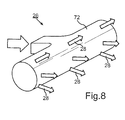
- Fig. 8 shows a schematic representation of an inlet nozzle 26 according to a third embodiment for use in the device 10.
- the housing 72 in the plan view is approximately T-shaped, with a portion of the housing 72 in turn for insertion and fixing in a corresponding opening a side wall or upper end wall or the rear wall of the installation space 12 or the process chamber is formed (see also FIG. 1 ).
- the projecting into the space 12 portion of the inlet nozzle 26 is cylindrical and has a plurality of openings through which the gas stream 28 in the direction of the building platform 14 and the corresponding assembly and joining zone 16 of the device 10 is passed.
- the inlet openings and the inside of the inlet 26th trained separator walls are in Fig. 8 not shown.
- the flow directions are again indicated by the arrows.
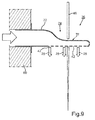
- FIGS. 9 to 11 show schematic representations of an inlet nozzle 26 according to a fourth embodiment for use in the device 10. It is in Fig. 9 a schematic, partially sectioned side view of the inlet nozzle 26 is shown. It can be seen that the housing 72 on the one hand is again fixed in an opening of the rear wall 60. In addition, the inlet nozzle 26 is in turn fluidly connected to a gas source for the process gas (not shown). The flow direction of the gas flow is indicated by the arrows. It can be seen that the gas stream 28 is deflected before it exits the inlet nozzle 26 by approximately 90 ° within the inlet nozzle 26, so that the gas stream 28 is directed in the direction of the building platform 14.
- a high energy beam 46 namely a laser beam can penetrate through the upper inlet nozzle 26.
- Fig. 10 which is a schematic sectional view of the inlet nozzle 26 according to FIG Fig. 9 is made clear, that in the region 74 of the inlet nozzle 26, a passage opening 76 is formed for the laser beam 46.
- the projecting into the space front section 74 of the inlet nozzle 26 is clip-like and approximately circular in shape and comprises two bent legs 78, 80, which enclose the passage opening 76.
- Separator walls 44 are again formed in the interior of the inlet nozzle 26, which divide the gas flow arriving from the gas source (see arrow) and lead into corresponding flow channels in the direction of the inlet openings 42.
- Fig. 11 which is a further schematic representation of the inlet nozzle 26 according to Fig. 9 represents. The design and shape of the inlet nozzle 26 becomes clear.
Abstract
Die Erfindung betrifft eine Vorrichtung (10) zur Herstellung oder Reparatur eines dreidimensionalen Objekts umfassend mindestens einen Bauraum (12) für ein schichtweises, aufeinanderfolgendes Verfestigen mindestens eines verfestigbaren Werkstoffs in vordefinierten Bereichen zum schichtweisen Aufbau des dreidimensionalen Objekts oder zur schichtweisen Reparatur einzelner Bereiche des dreidimensionalen Objekts innerhalb des Bauraums (12), und mindestens eine Einströmdüse (22, 26) und mindestens eine Absaugdüse (24) für ein Prozessgas, wobei die Einströmdüse (22, 26) und die Absaugdüse (24) derart angeordnet sind, dass ein zumindest teilweise über einer im Bauraum (12) ausgebildeten Bauplattform (14) verlaufender Gasstrom (30) ausgebildet wird. Zudem beträgt das Verhältnis der Summen der strömungstechnisch relevanten Querschnittsflächen der mindestens einen Absaugdüse (24) zu der mindestens einen Einströmdüse (22, 26) 2,5 : 1 bis 0,3 : 1. Die Erfindung betrifft weiterhin eine Absaugdüse (24) und eine Einströmdüse (26) zur Verwendung in einer Vorrichtung (10) zur generativen Herstellung oder Reparatur eines dreidimensionalen Objekts.The invention relates to a device (10) for producing or repairing a three-dimensional object comprising at least one installation space (12) for a layered, successive solidification of at least one solidifiable material in predefined areas for the layered construction of the three-dimensional object or for layerwise repair of individual areas of the three-dimensional object within the construction space (12), and at least one inlet nozzle (22, 26) and at least one suction nozzle (24) for a process gas, wherein the inlet nozzle (22, 26) and the suction nozzle (24) are arranged such that at least partially over a gas stream (30) extending in the building space (12) is formed. In addition, the ratio of the sums of the fluidically relevant cross-sectional areas of the at least one suction nozzle (24) to the at least one inlet nozzle (22, 26) is 2.5: 1 to 0.3: 1. The invention further relates to a suction nozzle (24) and a Injection nozzle (26) for use in a device (10) for the generative production or repair of a three-dimensional object.
Description
Die Erfindung betrifft eine Vorrichtung zur Herstellung oder Reparatur eines dreidimensionalen Objekts gemäß dem Oberbegriff des Anspruchs 1. Die Erfindung betrifft weiterhin eine Absaugdüse und eine Einströmdüse zur Verwendung in einer Vorrichtung zur generativen Herstellung oder Reparatur eines dreidimensionalen Objekts gemäß den Oberbegriffen der Ansprüche 14 und 15.The invention relates to a device for producing or repairing a three-dimensional object according to the preamble of claim 1. The invention further relates to a suction nozzle and an inlet nozzle for use in a device for the generative production or repair of a three-dimensional object according to the preambles of
Verfahren und Vorrichtungen zur Herstellung von dreidimensionalen Objekten, insbesondere von Bauteilen sind in einer großen Vielzahl bekannt. Insbesondere sind generative Fertigungsverfahren (sog. Rapid Manufacturing- bzw. Rapid Prototyping-Verfahren) bekannt, bei denen das dreidimensionale Objekt beziehungsweise das Bauteil durch pulverbettbasierte, additive Fertigungsverfahren schichtweise aufgebaut wird. Vorwiegend metallische Bauteile können beispielsweise durch Laser- bzw. Elektronenstrahlschmelz- oder -sinterverfahren hergestellt werden. Dabei wird zunächst schichtweise mindestens ein pulverförmiger Bauteilwerkstoff auf eine Bauteilplattform im Bereich einer Aufbau- und Fügezone der Vorrichtung aufgetragen. Anschließend wird der Bauteilwerkstoff schichtweise lokal verschmolzen und/oder versintert, indem dem Bauteilwerkstoff im Bereich der Aufbau- und Fügezone Energie mittels wenigstens eines Hochenergiestrahls, zum Beispiel eines Elektronen- oder Laserstrahls zugeführt wird. Der Hochenergiestrahl wird dabei in Abhängigkeit einer Schichtinformation der jeweils herzustellenden Bauteilschicht gesteuert. Nach dem Verschmelzen und/oder Versintern wird die Bauteilplattform schichtweise um eine vordefinierte Schichtdicke abgesenkt. Danach werden die genannten Schritte bis zur endgültigen Fertigstellung des Bauteils wiederholt. Vergleichbare additive Verfahren sind zur Herstellung von Keramik- oder Kunststoffelementen bekannt.Methods and apparatus for making three-dimensional objects, particularly components, are known in a wide variety. In particular, generative manufacturing methods (so-called rapid manufacturing or rapid prototyping methods) are known in which the three-dimensional object or the component is built up in layers by powder-bed-based, additive manufacturing processes. Primarily metallic components can be produced, for example, by laser or electron beam melting or sintering methods. In this case, at least one powdered component material is initially applied in layers to a component platform in the region of a buildup and joining zone of the device. Subsequently, the component material is locally fused in layers and / or sintered by the component material in the assembly and joining zone energy is supplied by means of at least one high-energy beam, for example an electron or laser beam. The high-energy beam is controlled in dependence on a layer information of the component layer to be produced in each case. After fusing and / or sintering, the component platform is lowered in layers by a predefined layer thickness. Thereafter, the said steps are repeated until the final completion of the component. Comparable additive processes are known for the production of ceramic or plastic elements.
Aus dem Stand der Technik sind insbesondere auch generative Herstellverfahren für die Herstellung von Bauteilen einer Strömungsmaschine, wie beispielsweise von Bauteilen eines Flugtriebwerks oder einer Gasturbine bekannt, z.B. das in der
Der Abtransport von Prozessnebenprodukten wird bei den gattungsgemäßen Vorrichtungen und Verfahren üblicherweise durch eine Schutzgasströmung umgesetzt, die meist über die genannte Bauteilplattform beziehungsweise eine Aufbau- und Fügezone geführt wird. Bekannte Vorrichtungen zur additiven Fertigung von dreidimensionalen Objekten umfassen dabei mehrere Einströmdüsen für das Schutzgas sowie mindestens eine Absaugdüse. Insbesondere werden Einströmdüsen verwendet, die einerseits seitlich über der Aufbau- und Fügezone und andererseits in einem der Aufbau- und Fügezone gegenüberliegenden oberen Bereich der Vorrichtung angeordnet sind. Die letztgenannte obere Einströmdüse hat aufgrund ihrer Geometrie und Lage direkten Einfluss auf den Volumenstrom und das Strömungsfeld des Schutzgasstroms im Bauraum beziehungsweise der Prozesskammer über der Bauteilplattform. Dabei kann die mittige Anordnung der oberen Einströmdüse im oberen Bereich der Vorrichtung zu einem inhomogenen Strömungsfeld und somit zu einem mangelnden Abtransport von Prozessnebenprodukten führen. Die Absaugdüse hat ebenfalls Einfluss auf das Strömungsfeld des Schutzgases. Bekannte Geometrien von Absaugdüsen können zu ungleichmäßigen Strömungsgeschwindigkeiten über die Düsenbreite führen. Zudem ist die Strömungsgeschwindigkeit an der Absaugdüse bei bekannten Vorrichtungen deutlich langsamer als die Strömungsgeschwindigkeit unmittelbar nach der Einströmdüse. Letzteres ist der Tatsache geschuldet, dass bei bekannten Vorrichtungen die Summe der strömungstechnisch relevanten Querschnittsflächen an den Eingängen der Absaugdüse, das heißt den Öffnungen der Absaugdüse, mindestens dreimal so groß ist, wie die Summe der strömungstechnisch relevanten Querschnittsflächen an den Ausgängen beziehungsweise Einströmöffnungen der oberen und unteren Einströmdüsen zusammen. Da aufgrund des Volumenstroms und der Querschnitte der Einström- und Absaugdüsen von einer Unterschallströmung und somit von inkompressiblen Strömungen ausgegangen werden kann, ergibt sich das Verhältnis der Strömungsgeschwindigkeiten an den Ein- und Auslassdüsen über die Verhältnisse der genannten strömungstechnisch relevanten Querschnittsflächen. Die genannten niedrigen Strömungsgeschwindigkeiten sowie das insgesamt inhomogene Strömungsfeld innerhalb der Bauräume der bekannten Vorrichtungen führen zu einem mangelnden Abtransport von Prozessnebenprodukten. So entstehen beispielsweise bei bekannten Vorrichtungen zum selektiven Laserstrahlschmelzen in bestimmten Bauraumbereichen vermehrt Fehler im Prozess und im Bauteil, sodass diese Bereiche für die Produktion von Serienbauteilen nicht geeignet sind. Diese Fehler entstehen insbesondere aufgrund des genannten mangelnden Abtransports von Prozessnebenprodukten. Bei Prozessnebenprodukten kann es sich bei dem selektiven Laserstrahlschmelzen insbesondere um Schmauch (Schweißrauch), Spritzer, Auswurf und verblasenes Pulver handeln. Besonders Schmauch führt zu einer Defokussierung und Abschirmung des Laserstrahls. Dadurch sinkt die auf den zu verschmelzenden Werkstoff einzubringende Energiedichte und das Pulver wird nur mangelhaft aufgeschmolzen. Es erfolgt eine mangelnde Anbindung an das Bauteil, wodurch wiederum Bindefehler im Bauteil entstehen können. Spritzer und Auswurf erhöhen zudem die Schichtdicke lokal deutlich. Dadurch können wiederum eine mangelnde Anbindung an das Bauteil und Bindefehler entstehen.The removal of process by-products is usually implemented in the generic devices and methods by a protective gas flow, which is usually performed on said component platform or a building and joining zone. Known devices for the additive production of three-dimensional objects comprise several inlet nozzles for the protective gas and at least one suction nozzle. In particular, inlet nozzles are used, which are arranged on the one side laterally above the assembly and joining zone and on the other hand in an upper region of the device opposite the assembly and joining zone. Due to their geometry and position, the latter upper inlet nozzle has a direct influence on the volume flow and the flow field of the protective gas flow in the installation space or the process chamber above the component platform. In this case, the central arrangement of the upper inlet nozzle in the upper region of the device can lead to an inhomogeneous flow field and thus to a lack of removal of process by-products. The suction nozzle also has an influence on the flow field of the protective gas. Known geometries of suction nozzles can lead to uneven flow velocities across the nozzle width. In addition, the flow rate at the suction nozzle in known devices is significantly slower than the flow velocity immediately after the inlet nozzle. The latter is due to the fact that in known devices, the sum of the fluidically relevant cross-sectional areas at the inputs of the suction nozzle, that is, the openings of the suction nozzle, at least three times as large as the sum of the fluidically relevant cross-sectional areas at the outputs or inlet openings of the upper and lower inlet nozzles together. Since, due to the volumetric flow and the cross sections of the inflow and suction nozzles, a subsonic flow and thus of incompressible flows can be assumed, the ratio of the flow velocities at the inlet and outlet nozzles results from the ratios of the fluidically relevant cross-sectional areas mentioned. The mentioned low flow velocities and the overall inhomogeneous flow field within the construction space of the known devices lead to a lack of removal of process by-products. Thus, for example, in known devices for selective laser beam melting in certain Space areas increase errors in the process and in the component, so that these areas are not suitable for the production of series components. These errors occur in particular due to the mentioned lack of removal of process by-products. In process by-products, selective laser beam melting may be, in particular, smoldering (fume), spattering, ejection, and fumed powder. Especially smoke leads to a defocusing and shielding of the laser beam. As a result, the energy density to be introduced onto the material to be fused sinks and the powder is melted only inadequately. There is a lack of connection to the component, which in turn can cause binding errors in the component. Splashes and ejection also increase the layer thickness locally significantly. This in turn may result in a lack of connection to the component and binding error.
Aufgabe der vorliegenden Erfindung ist es daher, eine Vorrichtung der eingangs genannten Art zu schaffen, die einen verbesserten Abtransport von bei additiven Fertigungsverfahren entstehenden Prozessnebenprodukten aus einem Bereich einer Aufbau- und Fügezone gewährleistet. Zudem besteht die Aufgabe, eine Absaugdüse und eine Einströmdüse zu schaffen, die ebenfalls einen verbesserten Abtransport von bei additiven Fertigungsverfahren entstehenden Prozessnebenprodukten aus einem Bereich einer Aufbau- und Fügezone einer Vorrichtung zur generativen Herstellung oder Reparatur eines dreidimensionalen Objekts gewährleisten.Object of the present invention is therefore to provide a device of the type mentioned above, which ensures an improved removal of resulting in additive manufacturing process by-products from one area of a building and joining zone. In addition, the object is to provide a suction nozzle and an inlet nozzle, which also ensure an improved removal of resulting in additive manufacturing process by-products from a range of building and joining zone of a device for generative production or repair of a three-dimensional object.
Diese Aufgabe wird erfindungsgemäß durch eine Vorrichtung zur Herstellung oder Reparatur eines dreidimensionalen Objekts mit den Merkmalen des Patentanspruchs 1 gelöst. Zudem wird diese Aufgabe durch eine Absaugdüse mit den Merkmalen des Anspruchs 14 und einer Einströmdüse gemäß den Merkmalen des Anspruchs 15 gelöst. Vorteilhafte Ausgestaltungen mit zweckmäßigen Weiterbildungen der Erfindung sind in den jeweiligen Unteransprüchen angegeben, wobei vorteilhafte Ausgestaltungen der Vorrichtung als vorteilhafte Ausgestaltungen der Absaugdüse sowie der Einströmdüse und umgekehrt anzusehen sind.This object is achieved by a device for producing or repairing a three-dimensional object with the features of claim 1. In addition, this object is achieved by a suction nozzle having the features of
Ein erster Aspekt der Erfindung betrifft eine Vorrichtung zur Herstellung oder Reparatur eines dreidimensionalen Objekts umfassend mindestens einen Bauraum für ein schichtweises, aufeinderfolgendes Verfestigen mindestens eines verfestigbaren Werkstoffs in vordefinierten Bereichen zum schichtweisen Aufbau eines dreidimensionalen Objekts oder zur schichtweisen Reparatur einzelner Bereiche des dreidimensionalen Objekts innerhalb des Bauraums und mindestens eine Einströmdüse sowie mindestens eine Absaugdüse für ein Prozessgas, wobei die Einströmdüse und die Absaugdüse derart angeordnet sind, dass ein zumindest teilweise über einer im Bauraum ausgebildeten Aufbau- und Fügezone einer Bauplattform verlaufender Gasstrom ausgebildet wird. Zudem beträgt das Verhältnis der Summen der strömungstechnisch relevanten Querschnittsflächen der mindestens einen Absaugdüse zu der mindestens einen Einströmdüse 2,5 : 1 (2,5 zu 1) bis 0,3 : 1 (0,3 zu 1). Das Verhältnis der Summen der strömungstechnisch relevanten Querschnittsflächen der mindestens einen Absaugdüse zu der mindestens einen Einströmdüse kann aber auch 2 : 1 bis 0,5 : 1, insbesondere 1,3 : 1 bis 0,7 : 1 betragen. Durch die im Vergleich zum Stand der Technik deutliche Verringerung des Verhältnisses der Summen der strömungstechnisch relevanten Querschnittsflächen, das heißt insbesondere das Verhältnis der Summe der Flächen der Absaugöffnungen der Absaugdüse zu der Summe der Flächen der Einströmöffnungen der Einströmdüse, wird eine deutliche Erhöhung der Strömungsgeschwindigkeit des Gasstroms im Bauraum erzielt. Dadurch ergibt sich eine Verbesserung des Abtransports von Prozessnebenprodukten bei der generativen Herstellung oder Reparatur des dreidimensionalen Objekts. Zudem ergibt sich ein homogeneres Strömungsfeld, was wiederum zur deutlichen Verbesserung des Abtransports der Prozessnebenprodukte beiträgt. Insbesondere sind dabei die mindestens eine Absaugdüse und die mindestens eine Einströmdüse derart ausgebildet, dass das Verhältnis der effektiven Strömungsgeschwindigkeiten der mindestens einen Absaugdüse zu der mindestens einen Einströmdüse 2,5 : 1 bis 0,3 : 1 beträgt. In vorteilhaften Ausgestaltungen der Erfindung kann das Verhältnis der effektiven Strömungsgeschwindigkeiten der mindestens einen Absaugdüse zu der mindestens einen Einströmdüse auch 2 : 1 bis 0,5 : 1, insbesondere 1,3 : 1 bis 0,7 : 1 betragen. Das Verhältnis der Summen der strömungstechnisch relevanten Querschnittsflächen der Absaugdüsen zu den Einströmdüsen sowie das Verhältnis der effektiven Strömungsgeschwindigkeiten der Absaugdüsen zu den Einströmdüsen beträgt bei Vorrichtungen gemäß dem Stand der Technik 3 : 1 (3 zu 1) und mehr. Durch den verbesserten Abtransport von Prozessnebenprodukten ist zudem gewährleistet, dass beispielsweise ein Hochenergiestrahl, wie ein Laserstrahl, nicht mehr durch die entstehenden Prozessnebenprodukte abgeschirmt und defokussiert wird. Dies führt zu einer deutlichen Qualitätsverbesserung bei der Herstellung oder Reparatur des dreidimensionalen Objekts. Das eingesetzte Prozessgas ist insbesondere ein Schutz- oder Inertgas. Der Volumenstrom des Prozessgases innerhalb des Bauraums beträgt erfindungsgemäß 10 bis 200 m3/h, insbesondere 30 bis 150 m3/h oder 50 bis 80 m3/h. Die Strömungsgeschwindigkeiten betragen erfindungsgemäß unmittelbar nach der Einströmdüse und vor der Absaugdüse 0,5 bis 10 m/s, insbesondere 1,0 bis 8,0 m/s oder 2,0 bis 4,0 m/s. Derartige Volumenströme und Strömungsgeschwindigkeiten werden erfindungsgemäß durch die Ausgestaltung der strömungstechnisch relevanten Querschnittsflächen der Absaugdüse und der Einströmdüse und insbesondere durch das Verhältnis der Summen der strömungstechnisch relevanten Querschnittsflächen erzielt. Insbesondere werden Absaugdüsen bereitgestellt, die im Vergleich zu herkömmlichen Absaugdüsen deutlich geringere Querschnittsflächen der Absaugöffnungen aufweisen. So kann zum Beispiel eine Verkleinerung der genannten Querschnittsfläche um ca. 66 % erfolgen, wodurch die Strömungsgeschwindigkeit an der Absaugung um das ca. Dreifache erhöht wird. Die Strömungsgeschwindigkeit an den Absaugdüsen wird somit der Strömungsgeschwindigkeit an den Einströmdüsen erfindungsgemäß angenähert und angeglichen. Bei dem im Vorhergehenden beschriebenen Bauraum der Vorrichtung handelt es sich üblicherweise um eine Prozesskammer zur Durchführung des generativen Herstellungs- oder Reparaturverfahrens. Bei dem herzustellenden oder zu reparierenden dreidimensionalen Objekt kann es sich um ein Bauteil oder einen Bauteilbereich eines Flugtriebwerks, insbesondere eines Verdichters oder einer Turbine handeln. Der verwendete Werkstoff kann pulverförmig, flüssig oder pastös ausgebildet sein und besteht üblicherweise aus Metall, einer Metalllegierung, Keramik oder Kunststoff oder einer Mischung daraus.A first aspect of the invention relates to a device for producing or repairing a three-dimensional object comprising at least one construction space for a layered, successive solidification of at least one solidifiable material in predefined areas for the layered construction of a three-dimensional object or for the layered repair of individual areas of the three-dimensional object within the construction space and at least one Inlet nozzle and at least one suction nozzle for a process gas, wherein the inlet nozzle and the suction nozzle are arranged such that an at least partially over a building space formed in the construction and joining zone of a building platform extending gas flow is formed. In addition, the ratio of the sums of the fluidically relevant cross-sectional areas of the at least one suction nozzle to the at least one inlet nozzle is 2.5: 1 (2.5 to 1) to 0.3: 1 (0.3 to 1). However, the ratio of the sums of the fluidically relevant cross-sectional areas of the at least one suction nozzle to the at least one inlet nozzle can also be 2: 1 to 0.5: 1, in particular 1.3: 1 to 0.7: 1. Due to the significant reduction in the ratio of the sums of the fluidically relevant cross-sectional areas, ie in particular the ratio of the sum of the areas of the suction openings of the suction nozzle to the sum of the areas of the inlet openings of the inlet nozzle, a significant increase in the flow rate of the gas stream is achieved achieved in the space. This results in an improvement of the removal of process by-products in the generative production or repair of the three-dimensional object. In addition, a more homogeneous flow field results, which in turn contributes to the significant improvement of the removal of the process by-products. In particular, the at least one suction nozzle and the at least one inlet nozzle are designed such that the ratio of the effective flow velocities of the at least one suction nozzle to the at least one inlet nozzle is 2.5: 1 to 0.3: 1. In advantageous embodiments of the invention, the ratio of the effective flow velocities of the at least one suction nozzle to the at least one inlet nozzle can also be 2: 1 to 0.5: 1, in particular 1.3: 1 to 0.7: 1. The ratio of the sums of the fluidically relevant cross-sectional areas of the suction nozzles to the inlet nozzles and the ratio of the effective flow velocities of the suction nozzles to the inlet nozzles is 3: 1 (3 to 1) and more in devices according to the prior art. The improved removal of process by-products also ensures that, for example, a high-energy beam, such as a laser beam, is no longer shielded and defocused by the resulting process by-products. This leads to a significant quality improvement in the production or repair of the three-dimensional object. The process gas used is in particular a protective or inert gas. The volume flow of the process gas within the installation space is according to the
In weiteren vorteilhaften Ausgestaltungen der erfindungsgemäßen Vorrichtung umfasst die Absaugdüse mindestens eine Absaugöffnung, wobei die Absaugöffnung mit einem zugehörigen Absaugkanal strömungsleitend verbunden ist und der Strömungskanal Wandflächen aufweist, die in Strömungsrichtung einen zumindest abschnittsweise gewölbten Konturverlauf aufweisen. Durch das Vermeiden von Ecken und Kanten innerhalb des Strömungskanals ergibt sich wiederum eine Erhöhung der Strömungsgeschwindigkeit, da der Strömungswiderstand innerhalb des Strömungskanals durch den gewölbten Konturverlauf der Wandflächen, das heißt entsprechende Abrundungen deutlich reduziert wird. Des Weiteren besteht die Möglichkeit, dass die Absaugdüse mindestens zwei Absaugöffnungen umfasst, wobei die zugehörigen Absaugkanäle zumindest abschnittsweise voneinander getrennt sind. Dabei können die Absaugkanäle derart ausgebildet und dimensioniert sein, dass durch jeden Absaugkanal ein ungefähr gleicher Gasvolumenstrom fließt. Auch durch diese Maßnahme ergeben sich einerseits eine erhöhte Strömungsgeschwindigkeit in den Strömungskanälen und andererseits ein homogeneres Strömungsfeld im Bauraum der Vorrichtung. Des Weiteren besteht die Möglichkeit, dass der Absaugkanal derart ausgebildet ist, dass der abgesaugte Gasstrom in einer Ebene über und/oder unter der Abschnittsöffnung abgeleitet wird. Hierzu wird die Strömung nach dem Einlass in den Absaugkanal erst nach oben und/oder unten und dann zur Seite geleitet. Durch diese vorteilhafte Ausgestaltung ergibt sich eine kompaktere Bauweise der Absaugdüse, was zu einer konstruktiven Vereinfachung der Vorrichtung insgesamt führt. Des Weiteren besteht die Möglichkeit, dass die Absaugdüse eine Vielzahl von Absaugöffnungen umfasst, wobei zur Verringerung der strömungstechnisch relevanten Querschnittsfläche an einem Teilbereich der Absaugöffnungen mindestens eine Abdeckung angeordnet ist. Die Abdeckung kann dabei als separates Bauteil ausgebildet sein, es ist aber auch möglich den genannten Teilbereich der Absaugöffnungen mit einer entsprechenden Klebefolie zu bedecken. Insgesamt erfolgt bei der Konstruktion der erfindungsgemäßen Absaugdüsen eine deutliche Verringerung der Summe der strömungstechnisch relevanten Querschnittsflächen, insbesondere der Fläche der entsprechenden Absaugöffnungen der Absaugdüse. Durch die erfindungsgemäße Ausgestaltung der Absaugdüsen ergibt sich eine deutliche Erhöhung der Strömungsgeschwindigkeit des Gasstroms an der Absaugung, sodass im Bauraum der Vorrichtung entstehende Prozessnebenprodukte ohne Weiteres abtransportiert werden können.In further advantageous embodiments of the device according to the invention, the suction nozzle comprises at least one suction opening, wherein the suction opening is connected in flow-conducting manner with an associated suction channel and the flow channel has wall surfaces which have an at least sectionally curved contour profile in the flow direction. By avoiding corners and edges within the flow channel in turn results in an increase in the flow velocity, since the flow resistance within the flow channel by the curved contour of the wall surfaces, that is, corresponding rounding is significantly reduced. Furthermore, there is the possibility that the suction nozzle comprises at least two suction openings, wherein the associated suction channels are at least partially separated from each other. In this case, the suction channels can be designed and dimensioned such that an approximately equal gas volume flow flows through each suction channel. Also by this measure, on the one hand an increased flow velocity in the flow channels and on the other hand, a more homogeneous flow field in the space of the device arise. Furthermore, there is the possibility that the suction channel is designed such that the extracted gas stream is discharged in a plane above and / or below the section opening. For this purpose, the flow after the inlet into the suction is only up and / or down and then led to the side. This advantageous embodiment results in a more compact design of the suction nozzle, resulting in a constructive simplification of the device as a whole. Furthermore, there is the possibility that the suction nozzle comprises a plurality of suction openings, wherein at least one cover is arranged on a partial area of the suction openings in order to reduce the fluidically relevant cross-sectional area. The cover may be formed as a separate component, but it is also possible to cover said portion of the suction with a corresponding adhesive film. Overall, in the construction of the suction nozzles according to the invention, a significant reduction in the sum of the fluidically relevant cross-sectional areas, in particular the area of the corresponding suction openings of the suction nozzle. The inventive design of the suction nozzles results in a significant increase in the flow velocity of the gas stream at the suction, so that in the space of the device resulting process by-products can be easily removed.
In weiteren vorteilhaften Ausgestaltungen der erfindungsgemäßen Vorrichtung umfasst die Vorrichtung mindestens eine in einem der Bauplattform gegenüberliegenden oberen Bereich und/oder einer Seitenwand der Vorrichtung angeordnete obere Einströmdüse und/oder mindestens eine in einer Seitenwand der Vorrichtung über der Bauplattform und unterhalb der oberen Einströmdüse angeordnete untere Einströmdüse. Je nach Volumen des Bauraums können die Einströmdüsen vorteilhafterweise in unterschiedlichen Bereichen und auch in einer benötigten Anzahl zur Erzielung eines entsprechenden Strömungsvolumens des Prozessgases angeordnet werden. Dabei kann die obere Einströmdüse mindestens zwei Einströmöffnungen umfassen, wobei die Einströmöffnungen durch mindestens eine Separatorwand voneinander getrennt sind. Der ankommende Gasstrom des Prozessgases wird in der Einströmdüse aufgeteilt und in einzelne Einströmkanäle geleitet. Die Aufteilung der Gasströmung kann dabei beispielhaft durch horizontal und/oder vertikal angeordnete Separatorwände erfolgen. Zudem können die Einströmkanäle derart ausgelegt sein, dass die Ausströmgeschwindigkeit an jeder Stelle der Einströmdüse gleich ist. Dabei wird vorteilhafterweise die Düsenbreite so gewählt, dass sie zu einem auf der gesamten Bauplattform homogen verteilten Strömungsfeld des Prozessgases führt. Dadurch ergibt sich insgesamt eine Verbesserung der Homogenität des Strömungsfelds des Prozessgases innerhalb des Bauraums und insbesondere oberhalb der Bauplattform der Vorrichtung. In einer weiteren vorteilhaften Ausgestaltung der oberen Einströmdüse umfasst diese mindestens eine Durchtrittsöffnung für einen Hochenergiestrahl, insbesondere einen Laser- oder Elektronenstrahl oder einen Lichtstrahl, insbesondere einen UV-Lichtstrahl. Die Strömung des Prozessgases wird dabei wiederum in der Einströmdüse durch Separatorwände aufgeteilt und in Richtung der Bauplattform gelenkt. Insbesondere wird der Gasstrom bei einer seitlichen Anordnung der oberen Einströmdüse um ca. 90° nach unten in Richtung der Bauplattform gelenkt. Eine derartige Ausgestaltung der oberen Einströmdüse ermöglicht wiederum eine kompakte Ausgestaltung der Vorrichtung insgesamt.In further advantageous embodiments of the device according to the invention, the device comprises at least one upper inlet nozzle arranged in an upper region and / or a side wall of the device and / or at least one lower inlet nozzle arranged in a side wall of the device above the construction platform and below the upper inlet nozzle , Depending on the volume of the installation space, the inlet nozzles can advantageously be arranged in different areas and also in a required number to achieve a corresponding flow volume of the process gas. In this case, the upper inlet nozzle may comprise at least two inflow openings, wherein the inflow openings are separated from one another by at least one separator wall. The incoming gas stream of the process gas is divided in the inlet nozzle and directed into individual inflow channels. The distribution of the gas flow can be done by way of example by horizontally and / or vertically arranged Separatorwände. In addition, the inflow channels can be designed such that the outflow velocity is the same at each point of the inlet nozzle. In this case, advantageously, the nozzle width is selected so that it leads to a homogeneously distributed on the entire construction platform flow field of the process gas. This results in an overall improvement in the homogeneity of the flow field of the process gas within the installation space and in particular above the construction platform of the device. In a further advantageous embodiment of the upper inlet nozzle, this comprises at least one passage opening for a high energy beam, in particular a laser or electron beam or a Light beam, in particular a UV light beam. The flow of the process gas is in turn divided in the inlet nozzle by separator walls and directed in the direction of the construction platform. In particular, with a lateral arrangement of the upper inlet nozzle, the gas stream is directed downward by approximately 90 ° in the direction of the building platform. Such a design of the upper inlet nozzle in turn allows a compact design of the device as a whole.
In weiteren vorteilhaften Ausgestaltungen der erfindungsgemäßen Vorrichtung ist der Werkstoff pulverförmig, flüssig oder pastös ausgebildet und besteht aus Metall, einer Metalllegierung, Keramik oder Kunststoff oder einer Mischung daraus. Es ist aber auch möglich weitere, verfestigbare Werkstoffe innerhalb der erfindungsgemäßen Vorrichtung zur Herstellung oder Reparatur eines dreidimensionalen Objekts zu verwenden. Bei dem dreidimensionalen Objekt kann es sich insbesondere um ein Bauteil oder einen Bauteilbereich eines Flugtriebwerks, insbesondere eines Verdichters oder einer Turbine, handeln.In further advantageous embodiments of the device according to the invention, the material is powdered, liquid or pasty and consists of metal, a metal alloy, ceramic or plastic or a mixture thereof. However, it is also possible to use further, solidifiable materials within the device according to the invention for producing or repairing a three-dimensional object. The three-dimensional object may in particular be a component or a component region of an aircraft engine, in particular a compressor or a turbine.
Ein zweiter Aspekt der Erfindung betrifft eine Absaugdüse zur Verwendung in einer Vorrichtung zur generativen Herstellung oder Reparatur eines dreidimensionalen Objekts, wobei die Absaugdüse mindestens eine Absaugöffnung umfasst und die Absaugöffnung mit einem zugehörigen Absaugkanal strömungsleitend verbunden ist und der Strömungskanal Wandflächen aufweist, die in Strömungsrichtung einen zumindest abschnittsweise gewölbten Konturverlauf zeigen. Durch das Vermeiden von Ecken und Kanten innerhalb des Strömungskanals ergibt sich eine Erhöhung der Strömungsgeschwindigkeit, da der Strömungswiderstand innerhalb des Strömungskanals durch den gewölbten Konturverlauf der Wandflächen, das heißt entsprechende Abrundungen deutlich reduziert wird. Durch die deutliche Erhöhung der Strömungsgeschwindigkeit wird auch die Strömungsgeschwindigkeit des Gasstroms in einem Bauraum der Vorrichtung zur generativen Herstellung oder Reparatur eines dreidimensionalen Objekts erzielt. Dadurch ergibt sich eine Verbesserung des Abtransports von Prozessnebenprodukten bei der generativen Herstellung oder Reparatur des dreidimensionalen Objekts. Des Weiteren besteht die Möglichkeit, dass die Absaugdüse mindestens zwei Absaugöffnungen umfasst, wobei die zugehörigen Absaugkanäle zumindest abschnittsweise voneinander getrennt sind. Dabei können die Absaugkanäle derart ausgebildet und dimensioniert sein, dass durch jeden Absaugkanal ein ungefähr gleicher Gasvolumenstrom fließt. Auch durch diese Maßnahme ergibt sich einerseits eine erhöhte Strömungsgeschwindigkeit in den Strömungskanälen und andererseits ein homogeneres Strömungsfeld im Bauraum der Vorrichtung. Des Weiteren besteht die Möglichkeit, dass der Absaugkanal derart ausgebildet ist, dass der abgesaugte Gasstrom in einer Ebene über und/oder unter der Abschnittsöffnung abgeleitet wird. Hierzu wird die Strömung nach dem Einlass in den Absaugkanal erst nach oben und/oder unten und dann zur Seite geleitet. Durch diese vorteilhafte Ausgestaltung ergibt sich eine kompaktere Bauweise der Absaugdüse, was zu einer konstruktiven Vereinfachung der Vorrichtung insgesamt führt. Des Weiteren besteht die Möglichkeit, dass die Absaugdüse eine Vielzahl von Absaugöffnungen umfasst, wobei zur Verringerung einer strömungstechnisch relevanten Querschnittsfläche an einem Teilbereich der Absaugöffnungen mindestens eine Abdeckung angeordnet ist. Die Abdeckung kann dabei als separates Bauteil ausgebildet sein, es ist aber auch möglich den genannten Teilbereich der Absaugöffnungen mit einer entsprechenden Klebefolie zu bedecken. Insgesamt erfolgt bei der Konstruktion der erfindungsgemäßen Absaugdüsen eine deutliche Verringerung der Summe der strömungstechnisch relevanten Querschnittsflächen, insbesondere der Fläche der entsprechenden Absaugöffnungen der Absaugdüse. Durch die erfindungsgemäße Ausgestaltung der Absaugdüsen ergibt sich eine deutliche Erhöhung der Strömungsgeschwindigkeit des Gasstroms an der Absaugung, sodass im Bauraum der Vorrichtung entstehende Prozessnebenprodukte ohne Weiteres abtransportiert werden können. Die sich aus der Verwendung der Vorrichtung gemäß dem ersten Erfindungsaspekt ergebenden Merkmale und Vorteile sind den Beschreibungen des ersten Erfindungsaspekts zu entnehmen, wobei vorteilhafte Ausgestaltungen des ersten Erfindungsaspekts als vorteilhafte Ausgestaltungen des zweiten Erfindungsaspekts und umgekehrt anzusehen sind.A second aspect of the invention relates to a suction nozzle for use in a device for the generative production or repair of a three-dimensional object, wherein the suction nozzle comprises at least one suction opening and the suction opening is connected in flow-conducting manner with an associated suction channel and the flow channel has wall surfaces which at least one in the flow direction Sectionally curved contour show. By avoiding corners and edges within the flow channel results in an increase in the flow velocity, since the flow resistance within the flow channel by the curved contour of the wall surfaces, that is, corresponding rounding is significantly reduced. As a result of the marked increase in the flow velocity, the flow velocity of the gas stream is also achieved in a construction space of the device for the generative production or repair of a three-dimensional object. This results in an improvement of the removal of process by-products in the generative production or repair of the three-dimensional object. Furthermore, there is the possibility that the suction nozzle comprises at least two suction openings, wherein the associated suction channels are at least partially separated from each other. In this case, the suction channels can be designed and dimensioned such that an approximately equal gas volume flow flows through each suction channel. Also by this measure, on the one hand results in an increased flow velocity in the flow channels and on the other hand, a more homogeneous flow field in Space of the device. Furthermore, there is the possibility that the suction channel is designed such that the extracted gas stream is discharged in a plane above and / or below the section opening. For this purpose, the flow is passed after the inlet into the suction channel first up and / or down and then to the side. This advantageous embodiment results in a more compact design of the suction nozzle, resulting in a constructive simplification of the device as a whole. Furthermore, there is the possibility that the suction nozzle comprises a plurality of suction openings, wherein at least one cover is arranged at a partial area of the suction openings to reduce a fluidically relevant cross-sectional area. The cover may be formed as a separate component, but it is also possible to cover said portion of the suction with a corresponding adhesive film. Overall, in the construction of the suction nozzles according to the invention, a significant reduction in the sum of the fluidically relevant cross-sectional areas, in particular the area of the corresponding suction openings of the suction nozzle. The inventive design of the suction nozzles results in a significant increase in the flow velocity of the gas stream at the suction, so that in the space of the device resulting process by-products can be easily removed. The features and advantages resulting from the use of the device according to the first aspect of the invention can be taken from the descriptions of the first aspect of the invention, advantageous embodiments of the first aspect of the invention being regarded as advantageous embodiments of the second aspect of the invention and vice versa.
Ein dritter Aspekt der Erfindung betrifft eine Einströmdüse zur Verwendung in einer Vorrichtung zur generativen Herstellung oder Reparatur eines dreidimensionalen Objekts, wobei die Einströmdüse mindestens zwei Einströmöffnungen umfasst und die Einströmöffnungen durch mindestens eine Separatorwand voneinander getrennt sind. Erfindungsgemäß wird ein ankommender Gasstrom eines Prozessgases wird in der Einströmdüse aufgeteilt und in einzelne Einströmkanäle geleitet. Die Aufteilung der Gasströmung kann dabei beispielhaft durch horizontal und/oder vertikal angeordnete Separatorwände erfolgen. Zudem können die Einströmkanäle derart ausgelegt sein, dass die Ausströmgeschwindigkeit an jeder Stelle der Einströmdüse gleich ist. Dabei wird vorteilhafterweise die Düsenbreite so gewählt, dass sie zu einem auf einer gesamten Bauplattform der Vorrichtung zur generativen Herstellung oder Reparatur eines dreidimensionalen Objekts homogen verteilten Strömungsfeld des Prozessgases führt. Dadurch ergibt sich insgesamt eine Verbesserung der Homogenität des Strömungsfelds des Prozessgases innerhalb des Bauraums und insbesondere oberhalb der Bauplattform der Vorrichtung. In einer weiteren vorteilhaften Ausgestaltung der oberen Einströmdüse umfasst diese mindestens eine Durchtrittsöffnung für einen Hochenergiestrahl, insbesondere einen Laser- oder Elektronenstrahl oder einen Lichtstrahl, insbesondere einen UV-Lichtstrahl. Die Strömung des Prozessgases wird dabei wiederum in der Einströmdüse durch Separatorwände aufgeteilt und in Richtung der Bauplattform gelenkt. Insbesondere wird der Gasstrom bei einer seitlichen Anordnung der oberen Einströmdüse um ca. 90° nach unten in Richtung der Bauplattform gelenkt. Eine derartige Ausgestaltung der oberen Einströmdüse ermöglicht wiederum eine kompakte Ausgestaltung der Vorrichtung insgesamt. Durch die erfindungsgemäße Ausgestaltung der Einströmdüse ergibt sich eine deutliche Verbesserung der Homogenität des Strömungsfelds des Prozessgases über der Bauplattform im Bauraum, sodass im Bauraum der Vorrichtung entstehende Prozessnebenprodukte ohne Weiteres gleichmäßig abtransportiert werden können.A third aspect of the invention relates to an inlet nozzle for use in a device for the generative production or repair of a three-dimensional object, wherein the inlet nozzle comprises at least two inflow openings and the inflow openings are separated from one another by at least one separator wall. According to the invention, an incoming gas stream of a process gas is split in the inlet nozzle and directed into individual inflow channels. The distribution of the gas flow can be done by way of example by horizontally and / or vertically arranged Separatorwände. In addition, the inflow channels can be designed such that the outflow velocity is the same at each point of the inlet nozzle. In this case, the nozzle width is advantageously chosen such that it leads to a flow field of the process gas homogeneously distributed over an entire construction platform of the apparatus for the generative production or repair of a three-dimensional object. This results in an overall improvement in the homogeneity of the flow field of the process gas within the installation space and especially above the build platform of the device. In a further advantageous embodiment of the upper inlet nozzle, this comprises at least one passage opening for a high energy beam, in particular a laser or electron beam or a light beam, in particular a UV light beam. The flow of the process gas is in turn divided in the inlet nozzle by separator walls and directed in the direction of the construction platform. In particular, with a lateral arrangement of the upper inlet nozzle, the gas stream is directed downward by approximately 90 ° in the direction of the building platform. Such a design of the upper inlet nozzle in turn allows a compact design of the device as a whole. The inventive design of the inlet nozzle results in a significant improvement in the homogeneity of the flow field of the process gas over the build platform in the space, so that in the space of the device resulting process by-products can be easily removed evenly.
Des Weiteren bestehen die Möglichkeiten, dass die mindestens eine Einströmdüse in einem der Bauplattform gegenüberliegenden oberen Bereich und/oder einer Seitenwand der Vorrichtung angeordnet ist. Die sich aus der Verwendung der Vorrichtung gemäß dem ersten Erfindungsaspekt ergebenden Merkmale und Vorteile sind den Beschreibungen des ersten Erfindungsaspekts zu entnehmen, wobei vorteilhafte Ausgestaltungen des ersten Erfindungsaspekts als vorteilhafte Ausgestaltungen des dritten sowie des zweiten Erfindungsaspekts und umgekehrt anzusehen sind.Furthermore, there are the possibilities that the at least one inlet nozzle is arranged in an upper region opposite the construction platform and / or a side wall of the device. The features and advantages resulting from the use of the device according to the first aspect of the invention are to be taken from the descriptions of the first aspect of the invention, advantageous embodiments of the first aspect of the invention being regarded as advantageous embodiments of the third and the second aspects of the invention and vice versa.
Weitere Merkmale der Erfindung ergeben sich aus den Ansprüchen, den Ausführungsbeispielen sowie anhand der Zeichnungen. Die vorstehend in der Beschreibung genannten Merkmale und Merkmalskombinationen sowie die nachfolgend in den Ausführungsbeispielen genannten Merkmale und Merkmalskombinationen sind nicht nur in der jeweils angegebenen Kombination, sondern auch in anderen Kombinationen verwendbar, ohne den Rahmen der Erfindung zu verlassen.Further features of the invention will become apparent from the claims, the exemplary embodiments and with reference to the drawings. The features and combinations of features mentioned above in the description as well as the features and combinations of features mentioned below in the exemplary embodiments can be used not only in the particular combination specified, but also in other combinations, without departing from the scope of the invention.
Dabei zeigt:
- Fig. 1
- eine schematische Darstellung einer erfindungsgemäßen Vorrichtung zur Herstellung oder Reparatur eines dreidimensionalen Objekts;
- Fig. 2a
- eine schematische Darstellung einer Absaugdüse gemäß dem Stand der Technik;
- Fig. 2b
- eine schematische Darstellung einer Absaugdüse gemäß einer ersten Ausführungsform zur Verwendung in der erfindungsgemäßen Vorrichtung;
- Fig. 3a
- eine schematische Darstellung einer Absaugdüse gemäß dem Stand der Technik;
- Fig. 3b
- eine schematische Darstellung einer Absaugdüse gemäß einer zweiten Ausführungsform zur Verwendung in der erfindungsgemäßen Vorrichtung;
- Fig. 4
- eine schematische Darstellung einer Absaugdüse gemäß einer dritten Ausführungsform zur Verwendung in der erfindungsgemäßen Vorrichtung;
- Fig. 5
- eine schematische Darstellung einer Absaugdüse gemäß einer vierten Ausführungsform zur Verwendung in der erfindungsgemäßen Vorrichtung;
- Fig. 6
- eine schematische Schnittdarstellung einer Einströmdüse gemäß einer ersten Ausführungsform zur Verwendung in der erfindungsgemäßen Vorrichtung;
- Fig. 7
- eine schematische Schnittdarstellung einer Einströmdüse gemäß einer zweiten Ausführungsform zur Verwendung in der erfindungsgemäßen Vorrichtung;
- Fig. 8
- eine schematische Darstellung einer Einströmdüse gemäß einer dritten Ausführungsform zur Verwendung in der erfindungsgemäßen Vorrichtung;
- Fig. 9
- eine schematische, teilweise geschnittene seitliche Darstellung einer Einströmdüse gemäß einer vierten Ausführungsform zur Verwendung in der erfindungsgemäßen Vorrichtung;
- Fig. 10
- eine schematische Schnittdarstellung der Einströmdüse gemäß
Figur 9 ; und - Fig. 11
- eine schematisch dargestellte Ansicht der Einströmdüse gemäß
Figur 9 .
- Fig. 1
- a schematic representation of an apparatus according to the invention for the production or repair of a three-dimensional object;
- Fig. 2a
- a schematic representation of a suction nozzle according to the prior art;
- Fig. 2b
- a schematic representation of a suction nozzle according to a first embodiment for use in the device according to the invention;
- Fig. 3a
- a schematic representation of a suction nozzle according to the prior art;
- Fig. 3b
- a schematic representation of a suction nozzle according to a second embodiment for use in the device according to the invention;
- Fig. 4
- a schematic representation of a suction nozzle according to a third embodiment for use in the device according to the invention;
- Fig. 5
- a schematic representation of a suction nozzle according to a fourth embodiment for use in the device according to the invention;
- Fig. 6
- a schematic sectional view of an inlet nozzle according to a first embodiment for use in the device according to the invention;
- Fig. 7
- a schematic sectional view of an inlet nozzle according to a second embodiment for use in the device according to the invention;
- Fig. 8
- a schematic representation of an inlet nozzle according to a third embodiment for use in the device according to the invention;
- Fig. 9
- a schematic, partially sectioned side view of an inlet nozzle according to a fourth embodiment for use in the device according to the invention;
- Fig. 10
- a schematic sectional view of the inlet according to
FIG. 9 ; and - Fig. 11
- a schematically illustrated view of the inlet according to
FIG. 9 ,
Der Bauteilwerkstoff (nicht dargestellt) ist in dem beschriebenen Ausführungsbeispiel pulverförmig ausgebildet. Insbesondere handelt es sich um ein Pulver aus Metall oder einer Metalllegierung. Es besteht aber auch die Möglichkeit, dass in anderen Ausführungsbeispielen weitere Werkstoffe wie zum Beispiel Keramik oder Kunststoff oder eine Mischung aus Metall, Metalllegierung, Keramik oder Kunststoff verwendet wird. Zudem besteht die Möglichkeit, dass der Werkstoff nicht nur pulverförmig, sondern auch pastös oder flüssig aufgebildet sein kann. Gegebenenfalls werden bei Verwendung derartiger Bauteilwerkstoffe andere Auftragsverfahren mittels des Beschichters angewandt.The component material (not shown) is powdered in the described embodiment. In particular, it is a powder of metal or a metal alloy. But there is also the possibility that in other embodiments, other materials such as ceramic or plastic or a mixture of metal, metal alloy, ceramic or plastic is used. In addition, there is the possibility that the material may not only be powdered but also pasty or liquid. Optionally, other application methods by means of the coater are used when using such component materials.
Die Vorrichtung 10 umfasst des Weiteren mindestens eine Strahlungsquelle (nicht dargestellt) zum Erzeugen eines Hochenergiestrahls 46 (siehe auch
Des Weiteren erkannt man, dass neben der Bauplattform 14 ein Überlaufbehälter 20 zur Aufnahme von überschüssigem Werkstoff angeordnet ist. Dabei wird der überschüssige Werkstoff mittels des Beschichters 18 beziehungsweise einer an dem Beschichter 18 angeordneten Klinge (nicht dargestellt) von der Bauplattform 14 in den Überlaufbehälter 20 verbracht.Furthermore, it is recognized that in addition to the
Das Verhältnis der Summen der strömungstechnisch relevanten Querschnittsflächen der Absaugdüse 24 zu den Einströmdüsen 22, 26 beträgt 2,5 : 1 bis 0,3 : 1. Dies wird über eine deutliche Verringerung der Summe der strömungstechnisch relevanten Querschnittsflächen, nämlich den Absaugöffnungen 32 der Absaugdüse 24 erzielt. Durch eine derartige Ausgestaltung der Absaugdüse 24 ergibt sich zudem ein Verhältnis der effektiven Strömungsgeschwindigkeiten der Absaugdüse 24 zu den Einströmdüsen 22, 26 von 2,5 : 1 bis 0,3 : 1.The ratio of the sums of the fluidically relevant cross-sectional areas of the
Im Gegensatz dazu zeigt die
Die
- 1010
- Vorrichtungcontraption
- 1212
- Bauraumspace
- 1414
- Bauplattformbuilding platform
- 1616
- Aufbau- und FügezoneAssembly and joining zone
- 1818
- Beschichtercoaters
- 2020
- ÜberlaufbehälterOverflow tank
- 2222
- Untere EinströmdüseLower inlet nozzle
- 2424
- Absaugdüsesuction nozzle
- 2626
- Obere EinströmdüseUpper inlet nozzle
- 2828
- Gasstromgas flow
- 3030
- Gasstromgas flow
- 3232
- Absaugöffnungsuction
- 3434
- Abdeckungcover
- 3636
- Absaugkanalsuction
- 3838
- Wandflächenwall surfaces
- 4040
- SeitenwandSide wall
- 4242
- Einströmöffnunginflow
- 4444
- Separatorwandseparator wall
- 4646
- HochenergiestrahlHigh energy beam
- 4848
- Strömungskanalflow channel
- 5050
- Gehäusecasing
- 5252
- Kanalwandchannel wall
- 54a54a
- Gehäuseabschnitthousing section
- 54b54b
- Gehäuseabschnitthousing section
- 5656
- Kanalendechannel end
- 5858
- SeitenwandSide wall
- 6060
- Rückwandrear wall
- 6262
- Obere AbschlusswandUpper end wall
- 6464
- Absaugöffnungsuction
- 6666
- Strömungskanalflow channel
- 6868
- Wändewalls
- 7070
- Einlassinlet
- 7272
- Gehäusecasing
- 7474
- Gehäuseabschnitthousing section
- 7676
- DurchtrittsöffnungThrough opening
- 7878
- Schenkelleg
- 8080
- Schenkelleg
- 8282
- Vorderwandfront wall
Claims (15)
das Verhältnis der Summen der strömungstechnisch relevanten Querschnittsflächen der mindestens einen Absaugdüse (24) zu der mindestens einen Einströmdüse (22, 26) 2,5 : 1 bis 0,3 : 1 beträgt.Device (10) for producing or repairing a three-dimensional object comprising:
the ratio of the sums of the fluidically relevant cross-sectional areas of the at least one suction nozzle (24) to the at least one inlet nozzle (22, 26) is 2.5: 1 to 0.3: 1.
dadurch gekennzeichnet, dass
das Verhältnis der Summen der strömungstechnisch relevanten Querschnittsflächen der mindestens einen Absaugdüse (24) zu der mindestens einen Einströmdüse (22, 26) 2 : 1 bis 0,5 : 1, insbesondere 1,3 : 1 bis 0,7 : 1, beträgt.Device (10) according to claim 1,
characterized in that
the ratio of the sums of the fluidically relevant cross-sectional areas of the at least one suction nozzle (24) to the at least one inlet nozzle (22, 26) is 2: 1 to 0.5: 1, in particular 1.3: 1 to 0.7: 1.
dadurch gekennzeichnet, dass
die mindestens eine Absaugdüse (24) und die mindestens eine Einströmdüse (22, 26) derart ausgebildet sind, dass das Verhältnis der effektiven Strömungsgeschwindigkeiten der mindestens einen Absaugdüse (24) zu der mindestens einen Einströmdüse (22, 26) 2,5 : 1 bis 0,3 : 1 beträgt.Device (10) according to claim 1 or 2,
characterized in that
the at least one suction nozzle (24) and the at least one inlet nozzle (22, 26) are designed such that the ratio of the effective flow velocities of the at least one suction nozzle (24) to the at least one inlet nozzle (22, 26) is 2.5: 1 to 0.3: 1.
dadurch gekennzeichnet, dass
das Verhältnis der effektiven Strömungsgeschwindigkeiten der mindestens einen Absaugdüse (24) zu der mindestens einen Einströmdüse (22, 26) 2 : 1 bis 0,5 : 1, insbesondere 1,3 : 1 bis 0,7 : 1, beträgt.Device (10) according to claim 3,
characterized in that
the ratio of the effective flow velocities of the at least one suction nozzle (24) to the at least one inlet nozzle (22, 26) is 2: 1 to 0.5: 1, in particular 1.3: 1 to 0.7: 1.
dadurch gekennzeichnet, dass
die Absaugdüse (24) mindestens eine Absaugöffnung (32) umfasst, wobei die Absaugöffnung (32) mit einem zugehörigen Absaugkanal (36) strömungsleitend verbunden ist und der Strömungskanal (36) Wandflächen (38) aufweist, die in Strömungsrichtung einen zumindest abschnittsweise gewölbten Konturverlauf aufweisen.Device (10) according to one of the preceding claims,
characterized in that
the suction nozzle (24) comprises at least one suction opening (32), wherein the suction opening (32) is flow-connected to an associated suction channel (36) and the flow channel (36) has wall surfaces (38) which have an at least sectionally curved contour profile in the flow direction ,
dadurch gekennzeichnet, dass
die Absaugdüse (24) mindestens zwei Absaugöffnungen (32) umfasst, wobei die zugehörigen Absaugkanäle (36) zumindest abschnittsweise voneinander getrennt sind.Device (10) according to claim 5,
characterized in that
the suction nozzle (24) comprises at least two suction openings (32), wherein the associated suction channels (36) are at least partially separated from one another.
dadurch gekennzeichnet, dass
die Absaugkanäle (36) derart ausgebildet und dimensioniert sind, dass durch jeden Absaugkanal (36) ein ungefähr gleicher Gasvolumenstrom fließt.Device (10) according to claim 6,
characterized in that
the suction channels (36) are designed and dimensioned in such a way that an approximately equal gas volume flow flows through each suction channel (36).
dadurch gekennzeichnet, dass
der Absaugkanal (36) derart ausgebildet ist, dass der abgesaugte Gasstrom in einer Ebene über und/oder unter der Absaugöffnung (32) abgeleitet wird.Device (10) according to one of claims 5 to 7,
characterized in that
the suction channel (36) is designed such that the extracted gas stream is discharged in a plane above and / or below the suction opening (32).
dadurch gekennzeichnet, dass
die Absaugdüse (24) eine Vielzahl von Absaugöffnungen (32) umfasst, wobei zur Verringerung der strömungstechnisch relevanten Querschnittsfläche an einem Teilbereich der Absaugöffnungen (32) mindestens eine Abdeckung (34) angeordnet ist.Device (10) according to one of the preceding claims,
characterized in that
the suction nozzle (24) comprises a multiplicity of suction openings (32), wherein at least one cover (34) is arranged on a partial area of the suction openings (32) to reduce the fluidically relevant cross-sectional area.
dadurch gekennzeichnet, dass
die Vorrichtung (10) mindestens eine in einem der Bauplattform (14) gegenüberliegenden oberen Bereich und/oder einer Seitenwand (60) der Vorrichtung (10) angeordnete obere Einströmdüse (26) und/oder mindestens eine in einer Seitenwand (60) der Vorrichtung (10) über der Bauplattform (14) und unterhalb der oberen Einströmdüse (26) angeordnete untere Einströmdüse (22) umfasst.Device (10) according to one of the preceding claims,
characterized in that
the device (10) has at least one upper inlet nozzle (26) arranged in an upper region and / or a side wall (60) of the device (10) and / or at least one in a side wall (60) of the device (FIG. 10) above the building platform (14) and below the upper inlet nozzle (26) arranged lower inlet nozzle (22).
dadurch gekennzeichnet, dass
die obere Einströmdüse (26) mindestens zwei Einströmöffnungen (42) umfasst, wobei die Einströmöffnungen (42) durch mindestens eine Separatorwand (44) voneinander getrennt sind.Device (10) according to claim 10,
characterized in that
the upper inlet nozzle (26) comprises at least two inflow openings (42), wherein the inflow openings (42) are separated from one another by at least one separator wall (44).
dadurch gekennzeichnet, dass
die Einströmöffnungen (42) derart ausgebildet und ausgerichtet sind, dass ein Gasstrom (28) in Richtung der Bauplattform (14) gelenkt ist.Device (10) according to claim 11,
characterized in that
the inflow openings (42) are designed and aligned such that a gas flow (28) is directed in the direction of the building platform (14).
dadurch gekennzeichnet, dass
die obere Einströmdüse (26) mindestens eine Durchtrittsöffnung (76) für einen Hochenergiestrahl (46), insbesondere einen Laser- oder Elektronenstrahl, oder Lichtstrahl, insbesondere einen UV-Lichtstrahl, aufweist.Device (10) according to one of claims 10 to 12,
characterized in that
the upper inlet nozzle (26) has at least one passage opening (76) for a high-energy beam (46), in particular a laser or electron beam, or light beam, in particular a UV light beam.
dadurch gekennzeichnet, dass
die Absaugdüse (24) mindestens eine Absaugöffnung (32) umfasst, wobei die Absaugöffnung (32) mit einem zugehörigen Absaugkanal (36) strömungsleitend verbunden ist und der Strömungskanal (36) Wandflächen (38) aufweist, die einen zumindest abschnittsweise gewölbten Konturverlauf aufweisen.Suction nozzle (24) for use in a device (10) for the generative production or repair of a three-dimensional object,
characterized in that
the suction nozzle (24) comprises at least one suction opening (32), wherein the suction opening (32) is flow-connected to an associated suction channel (36) and the flow channel (36) has wall surfaces (38) which have an at least partially curved contour profile.
dadurch gekennzeichnet, dass
die Einströmdüse (26) mindestens zwei Einströmöffnungen (42) umfasst, wobei die Einströmöffnungen (42) durch mindestens eine Separatorwand (44) voneinander getrennt sind.Injection nozzle (26) for use in a device (10) for the generative production or repair of a three-dimensional object,
characterized in that
the inlet nozzle (26) comprises at least two inlet openings (42), wherein the inlet openings (42) are separated from one another by at least one separator wall (44).
Priority Applications (2)
| Application Number | Priority Date | Filing Date | Title |
|---|---|---|---|
| EP14191026.5A EP3015197B1 (en) | 2014-10-30 | 2014-10-30 | Device for producing or repairing a three-dimensional object |
| US14/919,569 US10112236B2 (en) | 2014-10-30 | 2015-10-21 | Device and method for the manufacture or repair of a three-dimensional object |
Applications Claiming Priority (1)
| Application Number | Priority Date | Filing Date | Title |
|---|---|---|---|
| EP14191026.5A EP3015197B1 (en) | 2014-10-30 | 2014-10-30 | Device for producing or repairing a three-dimensional object |
Publications (2)
| Publication Number | Publication Date |
|---|---|
| EP3015197A1 true EP3015197A1 (en) | 2016-05-04 |
| EP3015197B1 EP3015197B1 (en) | 2017-03-08 |
Family
ID=51870851
Family Applications (1)
| Application Number | Title | Priority Date | Filing Date |
|---|---|---|---|
| EP14191026.5A Active EP3015197B1 (en) | 2014-10-30 | 2014-10-30 | Device for producing or repairing a three-dimensional object |
Country Status (2)
| Country | Link |
|---|---|
| US (1) | US10112236B2 (en) |
| EP (1) | EP3015197B1 (en) |
Cited By (8)
| Publication number | Priority date | Publication date | Assignee | Title |
|---|---|---|---|---|
| DE102016111660A1 (en) * | 2016-06-24 | 2017-12-28 | Trumpf Laser- Und Systemtechnik Gmbh | Powder drying in generative production |
| DE102016212082A1 (en) * | 2016-07-04 | 2018-01-04 | MTU Aero Engines AG | Device for laser melting with several suction devices |
| EP3321009A1 (en) * | 2016-11-14 | 2018-05-16 | CL Schutzrechtsverwaltungs GmbH | Apparatus for additive manufacturing of three-dimensional objects |
| DE102018108834A1 (en) * | 2018-04-13 | 2019-10-17 | Eos Gmbh Electro Optical Systems | Manufacturing apparatus and method for additive production with mobile gas outlet |
| DE102018210260A1 (en) * | 2018-06-22 | 2019-12-24 | Eos Gmbh Electro Optical Systems | Device and method for the generative production of a three-dimensional object |
| EP3369570B1 (en) | 2017-03-02 | 2021-08-25 | CL Schutzrechtsverwaltungs GmbH | Device for additive production of three-dimensional objects |
| WO2021249818A1 (en) | 2020-06-10 | 2021-12-16 | Trumpf Laser- Und Systemtechnik Gmbh | Suction channel in additive manufacturing |
| US11504772B2 (en) | 2018-09-07 | 2022-11-22 | Eos Gmbh Electro Optical Systems | Method for providing a flow for an additive manufacturing device |
Families Citing this family (28)
| Publication number | Priority date | Publication date | Assignee | Title |
|---|---|---|---|---|
| MX355451B (en) | 2014-06-20 | 2018-04-18 | Velo3D Inc | Apparatuses, systems and methods for three-dimensional printing. |
| CN108698126A (en) | 2015-12-10 | 2018-10-23 | 维洛3D公司 | Consummate 3 D-printing |
| US10434573B2 (en) | 2016-02-18 | 2019-10-08 | Velo3D, Inc. | Accurate three-dimensional printing |
| US11691343B2 (en) | 2016-06-29 | 2023-07-04 | Velo3D, Inc. | Three-dimensional printing and three-dimensional printers |
| EP3492244A1 (en) | 2016-06-29 | 2019-06-05 | VELO3D, Inc. | Three-dimensional printing system and method for three-dimensional printing |
| DE102016216678A1 (en) | 2016-09-02 | 2018-03-08 | Eos Gmbh Electro Optical Systems | Method and device for generatively producing a three-dimensional object |
| DE102016216682A1 (en) | 2016-09-02 | 2018-03-08 | Eos Gmbh Electro Optical Systems | Method and device for generatively producing a three-dimensional object |
| US20180126462A1 (en) | 2016-11-07 | 2018-05-10 | Velo3D, Inc. | Gas flow in three-dimensional printing |
| US11484970B2 (en) * | 2017-02-21 | 2022-11-01 | General Electric Company | Additive manufacturing system and method of forming an object in a powder bed |
| US10315252B2 (en) | 2017-03-02 | 2019-06-11 | Velo3D, Inc. | Three-dimensional printing of three-dimensional objects |
| EP3378584B1 (en) * | 2017-03-24 | 2021-10-27 | SLM Solutions Group AG | Device and method for producing a three-dimensional workpiece |
| US10449696B2 (en) | 2017-03-28 | 2019-10-22 | Velo3D, Inc. | Material manipulation in three-dimensional printing |
| EP3431211B1 (en) | 2017-07-20 | 2022-03-16 | General Electric Company | Method for manufacturing a hybrid article |
| US20190099943A1 (en) * | 2017-10-03 | 2019-04-04 | General Electric Company | Additive manufacturing method and apparatus |
| US10272525B1 (en) * | 2017-12-27 | 2019-04-30 | Velo3D, Inc. | Three-dimensional printing systems and methods of their use |
| JP7066878B2 (en) | 2018-06-01 | 2022-05-13 | アプライド マテリアルズ インコーポレイテッド | Air knife for additional manufacturing |
| WO2020033310A1 (en) * | 2018-08-06 | 2020-02-13 | Vulcanforms Inc. | Additive manufacturing system with gas flow head |
| US11802714B2 (en) * | 2019-05-31 | 2023-10-31 | Hamilton Sundstrand Corporation | Exhaust manifold for additive manufacturing |
| US11413817B2 (en) * | 2019-09-26 | 2022-08-16 | Applied Materials, Inc. | Air knife inlet and exhaust for additive manufacturing |
| US11400649B2 (en) * | 2019-09-26 | 2022-08-02 | Applied Materials, Inc. | Air knife assembly for additive manufacturing |
| DE102020115414A1 (en) * | 2020-06-10 | 2021-12-16 | Trumpf Laser- Und Systemtechnik Gmbh | MANUFACTURING DEVICE WITH LARGE AREA COVERING GAS FLOW |
| DE102020129419A1 (en) * | 2020-11-09 | 2022-05-12 | Trumpf Laser- Und Systemtechnik Gmbh | Process and device for the production of three-dimensional objects by selective hardening of a building material applied in layers |
| DE102020129413A1 (en) * | 2020-11-09 | 2022-05-12 | Trumpf Laser- Und Systemtechnik Gmbh | Process and device for the production of three-dimensional objects by selective hardening of a building material applied in layers |
| US11938539B2 (en) | 2021-04-16 | 2024-03-26 | General Electric Company | Additive manufacturing build units with process gas inertization systems |
| US11759861B2 (en) | 2021-04-16 | 2023-09-19 | General Electric Company | Additive manufacturing build units with process gas inertization systems |
| CN113319296B (en) * | 2021-05-28 | 2023-03-21 | 威斯坦(厦门)实业有限公司 | Be applied to small-size 3D printer's exhaust guiding device and small-size 3D printer |
| WO2023117053A1 (en) * | 2021-12-21 | 2023-06-29 | S&S Scheftner Gmbh | 3d printer with protruding structure for generating a gas curtain |
| DE102022201999A1 (en) | 2022-02-25 | 2023-08-31 | Eos Gmbh Electro Optical Systems | Flow modification element, flow device and flow method for an additive manufacturing device |
Citations (7)
| Publication number | Priority date | Publication date | Assignee | Title |
|---|---|---|---|---|
| DE19853947C1 (en) * | 1998-11-23 | 2000-02-24 | Fraunhofer Ges Forschung | Process chamber for selective laser fusing of material powder comprises a raised section in the cover surface above the structure volume, in which a window is arranged for the coupling in of the laser beam |
| DE10342883A1 (en) * | 2003-09-15 | 2005-05-04 | Trumpf Werkzeugmaschinen Gmbh | Method and device for producing a three-dimensional molded body |
| DE102004031881A1 (en) * | 2004-06-30 | 2006-01-26 | Concept Laser Gmbh | Device for sucking gases, vapors and/or particles out of working region of laser processing machine has suction opening(s) on inside of suction element positionable above working region with wall arrangement enclosing working region |
| DE102009051479A1 (en) | 2009-10-30 | 2011-05-05 | Mtu Aero Engines Gmbh | Method and device for producing a component of a turbomachine |
| EP2492084A1 (en) * | 2009-10-21 | 2012-08-29 | Panasonic Corporation | Process for producing three-dimensionally shaped object and device for producing same |
| WO2014199150A1 (en) * | 2013-06-11 | 2014-12-18 | Renishaw Plc | Additive manufacturing apparatus and method |
| WO2014202413A2 (en) * | 2013-06-20 | 2014-12-24 | MTU Aero Engines AG | Device and method for additively producing at least one component region of a component |
Family Cites Families (4)
| Publication number | Priority date | Publication date | Assignee | Title |
|---|---|---|---|---|
| AU9065991A (en) * | 1990-11-09 | 1992-06-11 | Dtm Corporation | Controlled gas flow for selective laser sintering |
| EP2862651B1 (en) * | 2013-10-15 | 2019-07-17 | SLM Solutions Group AG | Method and apparatus for producing a large three-dimensional work piece |
| DE102014205875A1 (en) * | 2014-03-28 | 2015-10-01 | Eos Gmbh Electro Optical Systems | Apparatus and method for layering a three-dimensional object |
| JP5941113B2 (en) * | 2014-09-30 | 2016-06-29 | ファナック株式会社 | Laser processing equipment that can expand the condensing diameter |
-
2014
- 2014-10-30 EP EP14191026.5A patent/EP3015197B1/en active Active
-
2015
- 2015-10-21 US US14/919,569 patent/US10112236B2/en active Active
Patent Citations (7)
| Publication number | Priority date | Publication date | Assignee | Title |
|---|---|---|---|---|
| DE19853947C1 (en) * | 1998-11-23 | 2000-02-24 | Fraunhofer Ges Forschung | Process chamber for selective laser fusing of material powder comprises a raised section in the cover surface above the structure volume, in which a window is arranged for the coupling in of the laser beam |
| DE10342883A1 (en) * | 2003-09-15 | 2005-05-04 | Trumpf Werkzeugmaschinen Gmbh | Method and device for producing a three-dimensional molded body |
| DE102004031881A1 (en) * | 2004-06-30 | 2006-01-26 | Concept Laser Gmbh | Device for sucking gases, vapors and/or particles out of working region of laser processing machine has suction opening(s) on inside of suction element positionable above working region with wall arrangement enclosing working region |
| EP2492084A1 (en) * | 2009-10-21 | 2012-08-29 | Panasonic Corporation | Process for producing three-dimensionally shaped object and device for producing same |
| DE102009051479A1 (en) | 2009-10-30 | 2011-05-05 | Mtu Aero Engines Gmbh | Method and device for producing a component of a turbomachine |
| WO2014199150A1 (en) * | 2013-06-11 | 2014-12-18 | Renishaw Plc | Additive manufacturing apparatus and method |
| WO2014202413A2 (en) * | 2013-06-20 | 2014-12-24 | MTU Aero Engines AG | Device and method for additively producing at least one component region of a component |
Cited By (10)
| Publication number | Priority date | Publication date | Assignee | Title |
|---|---|---|---|---|
| DE102016111660A1 (en) * | 2016-06-24 | 2017-12-28 | Trumpf Laser- Und Systemtechnik Gmbh | Powder drying in generative production |
| DE102016212082A1 (en) * | 2016-07-04 | 2018-01-04 | MTU Aero Engines AG | Device for laser melting with several suction devices |
| EP3321009A1 (en) * | 2016-11-14 | 2018-05-16 | CL Schutzrechtsverwaltungs GmbH | Apparatus for additive manufacturing of three-dimensional objects |
| US10987867B2 (en) | 2016-11-14 | 2021-04-27 | Concept Laser Gmbh | Apparatus for additive manufacturing of three-dimensional objects |
| EP3321009B1 (en) | 2016-11-14 | 2021-07-07 | CL Schutzrechtsverwaltungs GmbH | Apparatus for additive manufacturing of three-dimensional objects |
| EP3369570B1 (en) | 2017-03-02 | 2021-08-25 | CL Schutzrechtsverwaltungs GmbH | Device for additive production of three-dimensional objects |
| DE102018108834A1 (en) * | 2018-04-13 | 2019-10-17 | Eos Gmbh Electro Optical Systems | Manufacturing apparatus and method for additive production with mobile gas outlet |
| DE102018210260A1 (en) * | 2018-06-22 | 2019-12-24 | Eos Gmbh Electro Optical Systems | Device and method for the generative production of a three-dimensional object |
| US11504772B2 (en) | 2018-09-07 | 2022-11-22 | Eos Gmbh Electro Optical Systems | Method for providing a flow for an additive manufacturing device |
| WO2021249818A1 (en) | 2020-06-10 | 2021-12-16 | Trumpf Laser- Und Systemtechnik Gmbh | Suction channel in additive manufacturing |
Also Published As
| Publication number | Publication date |
|---|---|
| EP3015197B1 (en) | 2017-03-08 |
| US20160121398A1 (en) | 2016-05-05 |
| US10112236B2 (en) | 2018-10-30 |
Similar Documents
| Publication | Publication Date | Title |
|---|---|---|
| EP3015197B1 (en) | Device for producing or repairing a three-dimensional object | |
| EP3050648B1 (en) | Device and method for producing or repairing a three-dimensional object | |
| EP3552804B1 (en) | Method for producing a three-dimensional object | |
| EP3321009B1 (en) | Apparatus for additive manufacturing of three-dimensional objects | |
| EP3174654B1 (en) | Device and method for additively producing at least one component region of a component | |
| EP3122538B1 (en) | Device and method for producing a three-dimensional object layer by layer and nozzle for gasflow into the device | |
| DE102014212100A1 (en) | Generative production process and device for this purpose with oppositely directed inert gas streams | |
| EP2384882A1 (en) | Method for generative creation of a three dimensional object with spatial elements and method for producing a corresponding data set | |
| WO2014202413A2 (en) | Device and method for additively producing at least one component region of a component | |
| EP3328619B1 (en) | Method and device for producing a three-dimensional object | |
| WO2019001900A1 (en) | Suction device for additive production | |
| EP3914418B1 (en) | Process for beam processing of a plate or tubular workpiece | |
| EP3085519A1 (en) | Method and device for generating a three-dimensional object | |
| DE102014108081A1 (en) | Device and method for the generative production of at least one component region of a component | |
| DE102016213628A1 (en) | Device for additive manufacturing with optimized protective gas flow | |
| EP3212354B1 (en) | Device and method for the generative production of at least one area of a component | |
| DE102017201084A1 (en) | Process for additive production and coating apparatus | |
| DE102011011325A1 (en) | Method for generative production or repair of a component and component | |
| DE102013222865A1 (en) | Device for generating layers in layers and a method | |
| DE102016205437A1 (en) | Device and method for producing or repairing a three-dimensional object | |
| EP3386661B1 (en) | Device and method for producing a three-dimensional, shaped metal body | |
| DE102018215301A1 (en) | Device and method for additively producing a three-dimensional object | |
| EP3538315B1 (en) | Method of producing a cavity in a blade platform ; corresponding blade | |
| DE102010035506A1 (en) | Producing component comprising first and second component through powder injection molding, comprises providing first component as first green body and second component as second green body, connecting green bodies, debinding and sintering | |
| WO2017028834A1 (en) | Device and method for producing or repairing a three-dimensional object by means of a parabolic mirror |
Legal Events
| Date | Code | Title | Description |
|---|---|---|---|
| PUAI | Public reference made under article 153(3) epc to a published international application that has entered the european phase |
Free format text: ORIGINAL CODE: 0009012 |
|
| AK | Designated contracting states |
Kind code of ref document: A1 Designated state(s): AL AT BE BG CH CY CZ DE DK EE ES FI FR GB GR HR HU IE IS IT LI LT LU LV MC MK MT NL NO PL PT RO RS SE SI SK SM TR |
|
| AX | Request for extension of the european patent |
Extension state: BA ME |
|
| 17P | Request for examination filed |
Effective date: 20161010 |
|
| RBV | Designated contracting states (corrected) |
Designated state(s): AL AT BE BG CH CY CZ DE DK EE ES FI FR GB GR HR HU IE IS IT LI LT LU LV MC MK MT NL NO PL PT RO RS SE SI SK SM TR |
|
| GRAP | Despatch of communication of intention to grant a patent |
Free format text: ORIGINAL CODE: EPIDOSNIGR1 |
|
| INTG | Intention to grant announced |
Effective date: 20161207 |
|
| GRAS | Grant fee paid |
Free format text: ORIGINAL CODE: EPIDOSNIGR3 |
|
| GRAA | (expected) grant |
Free format text: ORIGINAL CODE: 0009210 |
|
| AK | Designated contracting states |
Kind code of ref document: B1 Designated state(s): AL AT BE BG CH CY CZ DE DK EE ES FI FR GB GR HR HU IE IS IT LI LT LU LV MC MK MT NL NO PL PT RO RS SE SI SK SM TR |
|
| REG | Reference to a national code |
Ref country code: GB Ref legal event code: FG4D Free format text: NOT ENGLISH |
|
| REG | Reference to a national code |
Ref country code: CH Ref legal event code: EP Ref country code: AT Ref legal event code: REF Ref document number: 873078 Country of ref document: AT Kind code of ref document: T Effective date: 20170315 |
|
| REG | Reference to a national code |
Ref country code: IE Ref legal event code: FG4D Free format text: LANGUAGE OF EP DOCUMENT: GERMAN |
|
| REG | Reference to a national code |
Ref country code: DE Ref legal event code: R096 Ref document number: 502014002906 Country of ref document: DE |
|
| REG | Reference to a national code |
Ref country code: LT Ref legal event code: MG4D |
|
| REG | Reference to a national code |
Ref country code: NL Ref legal event code: MP Effective date: 20170308 |
|
| PG25 | Lapsed in a contracting state [announced via postgrant information from national office to epo] |
Ref country code: FI Free format text: LAPSE BECAUSE OF FAILURE TO SUBMIT A TRANSLATION OF THE DESCRIPTION OR TO PAY THE FEE WITHIN THE PRESCRIBED TIME-LIMIT Effective date: 20170308 Ref country code: NO Free format text: LAPSE BECAUSE OF FAILURE TO SUBMIT A TRANSLATION OF THE DESCRIPTION OR TO PAY THE FEE WITHIN THE PRESCRIBED TIME-LIMIT Effective date: 20170608 Ref country code: LT Free format text: LAPSE BECAUSE OF FAILURE TO SUBMIT A TRANSLATION OF THE DESCRIPTION OR TO PAY THE FEE WITHIN THE PRESCRIBED TIME-LIMIT Effective date: 20170308 Ref country code: HR Free format text: LAPSE BECAUSE OF FAILURE TO SUBMIT A TRANSLATION OF THE DESCRIPTION OR TO PAY THE FEE WITHIN THE PRESCRIBED TIME-LIMIT Effective date: 20170308 Ref country code: GR Free format text: LAPSE BECAUSE OF FAILURE TO SUBMIT A TRANSLATION OF THE DESCRIPTION OR TO PAY THE FEE WITHIN THE PRESCRIBED TIME-LIMIT Effective date: 20170609 |
|
| PG25 | Lapsed in a contracting state [announced via postgrant information from national office to epo] |
Ref country code: RS Free format text: LAPSE BECAUSE OF FAILURE TO SUBMIT A TRANSLATION OF THE DESCRIPTION OR TO PAY THE FEE WITHIN THE PRESCRIBED TIME-LIMIT Effective date: 20170308 Ref country code: BG Free format text: LAPSE BECAUSE OF FAILURE TO SUBMIT A TRANSLATION OF THE DESCRIPTION OR TO PAY THE FEE WITHIN THE PRESCRIBED TIME-LIMIT Effective date: 20170608 Ref country code: ES Free format text: LAPSE BECAUSE OF FAILURE TO SUBMIT A TRANSLATION OF THE DESCRIPTION OR TO PAY THE FEE WITHIN THE PRESCRIBED TIME-LIMIT Effective date: 20170308 Ref country code: LV Free format text: LAPSE BECAUSE OF FAILURE TO SUBMIT A TRANSLATION OF THE DESCRIPTION OR TO PAY THE FEE WITHIN THE PRESCRIBED TIME-LIMIT Effective date: 20170308 Ref country code: SE Free format text: LAPSE BECAUSE OF FAILURE TO SUBMIT A TRANSLATION OF THE DESCRIPTION OR TO PAY THE FEE WITHIN THE PRESCRIBED TIME-LIMIT Effective date: 20170308 |
|
| PG25 | Lapsed in a contracting state [announced via postgrant information from national office to epo] |
Ref country code: NL Free format text: LAPSE BECAUSE OF FAILURE TO SUBMIT A TRANSLATION OF THE DESCRIPTION OR TO PAY THE FEE WITHIN THE PRESCRIBED TIME-LIMIT Effective date: 20170308 |
|
| REG | Reference to a national code |
Ref country code: FR Ref legal event code: PLFP Year of fee payment: 4 |
|
| PG25 | Lapsed in a contracting state [announced via postgrant information from national office to epo] |
Ref country code: RO Free format text: LAPSE BECAUSE OF FAILURE TO SUBMIT A TRANSLATION OF THE DESCRIPTION OR TO PAY THE FEE WITHIN THE PRESCRIBED TIME-LIMIT Effective date: 20170308 Ref country code: CZ Free format text: LAPSE BECAUSE OF FAILURE TO SUBMIT A TRANSLATION OF THE DESCRIPTION OR TO PAY THE FEE WITHIN THE PRESCRIBED TIME-LIMIT Effective date: 20170308 Ref country code: EE Free format text: LAPSE BECAUSE OF FAILURE TO SUBMIT A TRANSLATION OF THE DESCRIPTION OR TO PAY THE FEE WITHIN THE PRESCRIBED TIME-LIMIT Effective date: 20170308 Ref country code: IT Free format text: LAPSE BECAUSE OF FAILURE TO SUBMIT A TRANSLATION OF THE DESCRIPTION OR TO PAY THE FEE WITHIN THE PRESCRIBED TIME-LIMIT Effective date: 20170308 Ref country code: SK Free format text: LAPSE BECAUSE OF FAILURE TO SUBMIT A TRANSLATION OF THE DESCRIPTION OR TO PAY THE FEE WITHIN THE PRESCRIBED TIME-LIMIT Effective date: 20170308 |
|
| PG25 | Lapsed in a contracting state [announced via postgrant information from national office to epo] |
Ref country code: IS Free format text: LAPSE BECAUSE OF FAILURE TO SUBMIT A TRANSLATION OF THE DESCRIPTION OR TO PAY THE FEE WITHIN THE PRESCRIBED TIME-LIMIT Effective date: 20170708 Ref country code: SM Free format text: LAPSE BECAUSE OF FAILURE TO SUBMIT A TRANSLATION OF THE DESCRIPTION OR TO PAY THE FEE WITHIN THE PRESCRIBED TIME-LIMIT Effective date: 20170308 Ref country code: PT Free format text: LAPSE BECAUSE OF FAILURE TO SUBMIT A TRANSLATION OF THE DESCRIPTION OR TO PAY THE FEE WITHIN THE PRESCRIBED TIME-LIMIT Effective date: 20170710 Ref country code: PL Free format text: LAPSE BECAUSE OF FAILURE TO SUBMIT A TRANSLATION OF THE DESCRIPTION OR TO PAY THE FEE WITHIN THE PRESCRIBED TIME-LIMIT Effective date: 20170308 |
|
| REG | Reference to a national code |
Ref country code: DE Ref legal event code: R097 Ref document number: 502014002906 Country of ref document: DE |
|
| PLBE | No opposition filed within time limit |
Free format text: ORIGINAL CODE: 0009261 |
|
| STAA | Information on the status of an ep patent application or granted ep patent |
Free format text: STATUS: NO OPPOSITION FILED WITHIN TIME LIMIT |
|
| PG25 | Lapsed in a contracting state [announced via postgrant information from national office to epo] |
Ref country code: DK Free format text: LAPSE BECAUSE OF FAILURE TO SUBMIT A TRANSLATION OF THE DESCRIPTION OR TO PAY THE FEE WITHIN THE PRESCRIBED TIME-LIMIT Effective date: 20170308 |
|
| 26N | No opposition filed |
Effective date: 20171211 |
|
| PG25 | Lapsed in a contracting state [announced via postgrant information from national office to epo] |
Ref country code: SI Free format text: LAPSE BECAUSE OF FAILURE TO SUBMIT A TRANSLATION OF THE DESCRIPTION OR TO PAY THE FEE WITHIN THE PRESCRIBED TIME-LIMIT Effective date: 20170308 |
|
| PG25 | Lapsed in a contracting state [announced via postgrant information from national office to epo] |
Ref country code: MC Free format text: LAPSE BECAUSE OF FAILURE TO SUBMIT A TRANSLATION OF THE DESCRIPTION OR TO PAY THE FEE WITHIN THE PRESCRIBED TIME-LIMIT Effective date: 20170308 |
|
| REG | Reference to a national code |
Ref country code: CH Ref legal event code: PL |
|
| REG | Reference to a national code |
Ref country code: IE Ref legal event code: MM4A |
|
| PG25 | Lapsed in a contracting state [announced via postgrant information from national office to epo] |
Ref country code: LU Free format text: LAPSE BECAUSE OF NON-PAYMENT OF DUE FEES Effective date: 20171030 Ref country code: CH Free format text: LAPSE BECAUSE OF NON-PAYMENT OF DUE FEES Effective date: 20171031 Ref country code: LI Free format text: LAPSE BECAUSE OF NON-PAYMENT OF DUE FEES Effective date: 20171031 |
|
| REG | Reference to a national code |
Ref country code: BE Ref legal event code: MM Effective date: 20171031 |
|
| PG25 | Lapsed in a contracting state [announced via postgrant information from national office to epo] |
Ref country code: BE Free format text: LAPSE BECAUSE OF NON-PAYMENT OF DUE FEES Effective date: 20171031 |
|
| PG25 | Lapsed in a contracting state [announced via postgrant information from national office to epo] |
Ref country code: MT Free format text: LAPSE BECAUSE OF FAILURE TO SUBMIT A TRANSLATION OF THE DESCRIPTION OR TO PAY THE FEE WITHIN THE PRESCRIBED TIME-LIMIT Effective date: 20170308 |
|
| REG | Reference to a national code |
Ref country code: FR Ref legal event code: PLFP Year of fee payment: 5 |
|
| PG25 | Lapsed in a contracting state [announced via postgrant information from national office to epo] |
Ref country code: IE Free format text: LAPSE BECAUSE OF NON-PAYMENT OF DUE FEES Effective date: 20171030 |
|
| PG25 | Lapsed in a contracting state [announced via postgrant information from national office to epo] |
Ref country code: HU Free format text: LAPSE BECAUSE OF FAILURE TO SUBMIT A TRANSLATION OF THE DESCRIPTION OR TO PAY THE FEE WITHIN THE PRESCRIBED TIME-LIMIT; INVALID AB INITIO Effective date: 20141030 |
|
| PG25 | Lapsed in a contracting state [announced via postgrant information from national office to epo] |
Ref country code: CY Free format text: LAPSE BECAUSE OF FAILURE TO SUBMIT A TRANSLATION OF THE DESCRIPTION OR TO PAY THE FEE WITHIN THE PRESCRIBED TIME-LIMIT Effective date: 20170308 |
|
| PG25 | Lapsed in a contracting state [announced via postgrant information from national office to epo] |
Ref country code: MK Free format text: LAPSE BECAUSE OF FAILURE TO SUBMIT A TRANSLATION OF THE DESCRIPTION OR TO PAY THE FEE WITHIN THE PRESCRIBED TIME-LIMIT Effective date: 20170308 |
|
| PG25 | Lapsed in a contracting state [announced via postgrant information from national office to epo] |
Ref country code: TR Free format text: LAPSE BECAUSE OF FAILURE TO SUBMIT A TRANSLATION OF THE DESCRIPTION OR TO PAY THE FEE WITHIN THE PRESCRIBED TIME-LIMIT Effective date: 20170308 |
|
| PG25 | Lapsed in a contracting state [announced via postgrant information from national office to epo] |
Ref country code: AL Free format text: LAPSE BECAUSE OF FAILURE TO SUBMIT A TRANSLATION OF THE DESCRIPTION OR TO PAY THE FEE WITHIN THE PRESCRIBED TIME-LIMIT Effective date: 20170308 |
|
| REG | Reference to a national code |
Ref country code: AT Ref legal event code: MM01 Ref document number: 873078 Country of ref document: AT Kind code of ref document: T Effective date: 20191030 |
|
| PG25 | Lapsed in a contracting state [announced via postgrant information from national office to epo] |
Ref country code: AT Free format text: LAPSE BECAUSE OF NON-PAYMENT OF DUE FEES Effective date: 20191030 |
|
| PGFP | Annual fee paid to national office [announced via postgrant information from national office to epo] |
Ref country code: FR Payment date: 20221020 Year of fee payment: 9 |
|
| PGFP | Annual fee paid to national office [announced via postgrant information from national office to epo] |
Ref country code: GB Payment date: 20221024 Year of fee payment: 9 |
|
| PGFP | Annual fee paid to national office [announced via postgrant information from national office to epo] |
Ref country code: DE Payment date: 20231018 Year of fee payment: 10 |