EP3014248B1 - An apparatus and method employing sensor-based luminaires to detect areas of reduced visibility and their direction of movement - Google Patents
An apparatus and method employing sensor-based luminaires to detect areas of reduced visibility and their direction of movement Download PDFInfo
- Publication number
- EP3014248B1 EP3014248B1 EP14733368.6A EP14733368A EP3014248B1 EP 3014248 B1 EP3014248 B1 EP 3014248B1 EP 14733368 A EP14733368 A EP 14733368A EP 3014248 B1 EP3014248 B1 EP 3014248B1
- Authority
- EP
- European Patent Office
- Prior art keywords
- fog
- visibility
- light unit
- communication
- covered area
- Prior art date
- Legal status (The legal status is an assumption and is not a legal conclusion. Google has not performed a legal analysis and makes no representation as to the accuracy of the status listed.)
- Revoked
Links
- 238000000034 method Methods 0.000 title claims description 19
- 230000033001 locomotion Effects 0.000 title description 13
- 238000004891 communication Methods 0.000 claims description 33
- 238000013507 mapping Methods 0.000 claims description 10
- 238000007405 data analysis Methods 0.000 claims description 8
- 238000012544 monitoring process Methods 0.000 claims description 6
- 238000004590 computer program Methods 0.000 claims 1
- 238000001514 detection method Methods 0.000 description 11
- 230000007246 mechanism Effects 0.000 description 11
- 230000008447 perception Effects 0.000 description 6
- 238000012545 processing Methods 0.000 description 5
- 238000005516 engineering process Methods 0.000 description 4
- 238000010200 validation analysis Methods 0.000 description 4
- 238000004458 analytical method Methods 0.000 description 3
- 238000012423 maintenance Methods 0.000 description 3
- 230000002776 aggregation Effects 0.000 description 2
- 238000004220 aggregation Methods 0.000 description 2
- 230000008901 benefit Effects 0.000 description 2
- 230000005540 biological transmission Effects 0.000 description 2
- 230000001413 cellular effect Effects 0.000 description 2
- 239000000428 dust Substances 0.000 description 2
- 230000007613 environmental effect Effects 0.000 description 2
- 230000006870 function Effects 0.000 description 2
- 238000005259 measurement Methods 0.000 description 2
- 238000001556 precipitation Methods 0.000 description 2
- 230000008569 process Effects 0.000 description 2
- 238000006467 substitution reaction Methods 0.000 description 2
- 230000000007 visual effect Effects 0.000 description 2
- XLYOFNOQVPJJNP-UHFFFAOYSA-N water Substances O XLYOFNOQVPJJNP-UHFFFAOYSA-N 0.000 description 2
- 241000112598 Pseudoblennius percoides Species 0.000 description 1
- 230000002159 abnormal effect Effects 0.000 description 1
- 238000010521 absorption reaction Methods 0.000 description 1
- 230000009471 action Effects 0.000 description 1
- 230000006399 behavior Effects 0.000 description 1
- 238000003339 best practice Methods 0.000 description 1
- 230000008033 biological extinction Effects 0.000 description 1
- 238000004364 calculation method Methods 0.000 description 1
- 230000008859 change Effects 0.000 description 1
- 238000009833 condensation Methods 0.000 description 1
- 230000005494 condensation Effects 0.000 description 1
- 230000006378 damage Effects 0.000 description 1
- 238000013500 data storage Methods 0.000 description 1
- 230000034994 death Effects 0.000 description 1
- 231100000517 death Toxicity 0.000 description 1
- 230000000694 effects Effects 0.000 description 1
- 239000000835 fiber Substances 0.000 description 1
- 230000004927 fusion Effects 0.000 description 1
- 230000012010 growth Effects 0.000 description 1
- 238000003384 imaging method Methods 0.000 description 1
- 230000000977 initiatory effect Effects 0.000 description 1
- 238000011835 investigation Methods 0.000 description 1
- 230000004807 localization Effects 0.000 description 1
- 238000007726 management method Methods 0.000 description 1
- 239000003595 mist Substances 0.000 description 1
- 239000002245 particle Substances 0.000 description 1
- 230000002093 peripheral effect Effects 0.000 description 1
- 230000003449 preventive effect Effects 0.000 description 1
- 230000009467 reduction Effects 0.000 description 1
- 238000011160 research Methods 0.000 description 1
- 239000000779 smoke Substances 0.000 description 1
- 238000007619 statistical method Methods 0.000 description 1
- 230000000153 supplemental effect Effects 0.000 description 1
- 238000012360 testing method Methods 0.000 description 1
Images

Classifications
-
- G—PHYSICS
- G08—SIGNALLING
- G08G—TRAFFIC CONTROL SYSTEMS
- G08G1/00—Traffic control systems for road vehicles
- G08G1/09—Arrangements for giving variable traffic instructions
-
- G—PHYSICS
- G08—SIGNALLING
- G08G—TRAFFIC CONTROL SYSTEMS
- G08G1/00—Traffic control systems for road vehicles
- G08G1/01—Detecting movement of traffic to be counted or controlled
- G08G1/0104—Measuring and analyzing of parameters relative to traffic conditions
- G08G1/0108—Measuring and analyzing of parameters relative to traffic conditions based on the source of data
- G08G1/0116—Measuring and analyzing of parameters relative to traffic conditions based on the source of data from roadside infrastructure, e.g. beacons
-
- G—PHYSICS
- G08—SIGNALLING
- G08G—TRAFFIC CONTROL SYSTEMS
- G08G1/00—Traffic control systems for road vehicles
- G08G1/01—Detecting movement of traffic to be counted or controlled
- G08G1/0104—Measuring and analyzing of parameters relative to traffic conditions
- G08G1/0125—Traffic data processing
- G08G1/0133—Traffic data processing for classifying traffic situation
-
- G—PHYSICS
- G08—SIGNALLING
- G08G—TRAFFIC CONTROL SYSTEMS
- G08G1/00—Traffic control systems for road vehicles
- G08G1/01—Detecting movement of traffic to be counted or controlled
- G08G1/0104—Measuring and analyzing of parameters relative to traffic conditions
- G08G1/0137—Measuring and analyzing of parameters relative to traffic conditions for specific applications
- G08G1/0141—Measuring and analyzing of parameters relative to traffic conditions for specific applications for traffic information dissemination
-
- G—PHYSICS
- G08—SIGNALLING
- G08G—TRAFFIC CONTROL SYSTEMS
- G08G1/00—Traffic control systems for road vehicles
- G08G1/09—Arrangements for giving variable traffic instructions
- G08G1/0962—Arrangements for giving variable traffic instructions having an indicator mounted inside the vehicle, e.g. giving voice messages
- G08G1/0967—Systems involving transmission of highway information, e.g. weather, speed limits
- G08G1/096733—Systems involving transmission of highway information, e.g. weather, speed limits where a selection of the information might take place
- G08G1/096758—Systems involving transmission of highway information, e.g. weather, speed limits where a selection of the information might take place where no selection takes place on the transmitted or the received information
-
- G—PHYSICS
- G08—SIGNALLING
- G08G—TRAFFIC CONTROL SYSTEMS
- G08G1/00—Traffic control systems for road vehicles
- G08G1/09—Arrangements for giving variable traffic instructions
- G08G1/0962—Arrangements for giving variable traffic instructions having an indicator mounted inside the vehicle, e.g. giving voice messages
- G08G1/0967—Systems involving transmission of highway information, e.g. weather, speed limits
- G08G1/096766—Systems involving transmission of highway information, e.g. weather, speed limits where the system is characterised by the origin of the information transmission
- G08G1/096783—Systems involving transmission of highway information, e.g. weather, speed limits where the system is characterised by the origin of the information transmission where the origin of the information is a roadside individual element
-
- G—PHYSICS
- G01—MEASURING; TESTING
- G01N—INVESTIGATING OR ANALYSING MATERIALS BY DETERMINING THEIR CHEMICAL OR PHYSICAL PROPERTIES
- G01N21/00—Investigating or analysing materials by the use of optical means, i.e. using sub-millimetre waves, infrared, visible or ultraviolet light
- G01N21/17—Systems in which incident light is modified in accordance with the properties of the material investigated
- G01N21/47—Scattering, i.e. diffuse reflection
- G01N21/49—Scattering, i.e. diffuse reflection within a body or fluid
- G01N21/53—Scattering, i.e. diffuse reflection within a body or fluid within a flowing fluid, e.g. smoke
- G01N21/538—Scattering, i.e. diffuse reflection within a body or fluid within a flowing fluid, e.g. smoke for determining atmospheric attenuation and visibility
-
- Y—GENERAL TAGGING OF NEW TECHNOLOGICAL DEVELOPMENTS; GENERAL TAGGING OF CROSS-SECTIONAL TECHNOLOGIES SPANNING OVER SEVERAL SECTIONS OF THE IPC; TECHNICAL SUBJECTS COVERED BY FORMER USPC CROSS-REFERENCE ART COLLECTIONS [XRACs] AND DIGESTS
- Y02—TECHNOLOGIES OR APPLICATIONS FOR MITIGATION OR ADAPTATION AGAINST CLIMATE CHANGE
- Y02B—CLIMATE CHANGE MITIGATION TECHNOLOGIES RELATED TO BUILDINGS, e.g. HOUSING, HOUSE APPLIANCES OR RELATED END-USER APPLICATIONS
- Y02B20/00—Energy efficient lighting technologies, e.g. halogen lamps or gas discharge lamps
- Y02B20/72—Energy efficient lighting technologies, e.g. halogen lamps or gas discharge lamps in street lighting
Definitions
- the present invention is directed generally to employing outdoor lighting networks (OLNs) to detect and provide information related to areas of reduced visibility, and in particular information related to fog conditions. More particularly, various inventive methods and apparatus disclosed herein relate to deploying fog sensors on luminaires in such OLNs to independently treat and consolidate the sensed data in a fault-tolerant manner. By communicating with neighboring luminaires and/or with a centralized server, fog positioning and direction of movement is identified. Further, the present invention provides a means to disseminate fog detections to thereby alert drivers who may be approaching the fog covered area.
- OTNs outdoor lighting networks
- KR 20090100174A relates to a method of fog detection which uses cameras to detect variations in the strength of the detected light warning drivers against fog through the use of a roadside display panel. Images are captured by a camera which are then analyzed by a recognition technique to determine the mist in the images. Fog warnings can then be displayed to drivers via the display panel based on the captured images.
- outdoor lighting poles are natural choices to place surveillance cameras to monitoring streets, parking lots, parks, and other outdoor areas.
- OLNs are thus used not only to control and manage outdoor lighting units, but to transmit data from cameras installed on lighting poles to monitoring centers.
- the lighting units employed may also include lamps, video/image sensors, data storage, and communication and control modules that are connected with a centralized server directly or through other lighting units.
- Such an OLN system is described in co-pending patent application entitled " IMAGING SERVICE USING OUTDOOR LIGHTING NETWORKS" filed on September 22, 2011 in the US Patent and Trademark Office and afforded serial number 61/537945 .
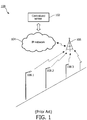
- FIG. 1 An example of a conventional outdoor lighting network 100 is shown in Figure 1 .
- light points or luminaires 108.1 -108.3 are in communication with an antenna tower 106 which, through an IP network 104, is in communication with a centralized server 102.
- a centralized server 102 It should be noted that various other means of communication are contemplated by the invention. These include power line communication or Radio Frequency (RF) mesh network of the light points.
- RF Radio Frequency
- the network connecting to the Centralized Server 102 may be wired, wireless and/or cellular networks. Still further, The Centralized Server 102 may also communicate with one or more light points directly if that light point is reachable through a cellular network.
- the light points of the OLN may communicate directly with each other without requiring the tower structure 106 or the centralized server 102 depicted in Fig. 1 .
- Such communication can be conducted by various means that are well-known in the art, to include wireless communication, wired communication (e.g., over power lines) and visual light communication.
- the current invention relates to the field of intelligent sensor-enabled luminaires capable of sensing the physical world, performing diverse calculations and manipulation of the sensed data pertaining to fog detection, and transmitting information to processors, controllers and mobile devices. These would include nearby vehicles, autonomous devices (e.g., self-driving cars and unmanned aerial vehicles), or internet-connected mobile devices (e.g., smartphones and tablets), as well as centralized data warehouses with internet-based user interfaced applications. Particularly, the current invention relates to:
- fog is a somewhat passive weather phenomenon. Still, it's known to catch motorists by surprise. Fog tends to form on clear, cool nights when moist air accumulates slightly above the ground or water. This air is mixed during the night to form condensation, which dissipates as the sun rises. The extreme variability of fog, especially in its density and location, make it difficult for motorists to perceive and react quickly. Since light is refracted and deflected by the water droplets of the fog, this event is not at all limited to early mornings, and in fact can affect both day and night driving conditions.
- Fog is measured by visibility in miles, and is considered severe when visibility is 1/4 mile or less.
- the foggiest location in the United States is located at Cape Disappointment, Washington, with 106 severe fog days per year. On the east coast, it is the city of Eastport, Maine that takes the prize with 65 days. In inland areas, the foggiest location is Elkins, West Virginia with 81 days. By way of comparison, further south in Tampa Bay, Florida, the average is of 22 days. In northern Utah, super-cooled fog ( ⁇ 32F) can persist in mountain valleys for weeks [http://ops.fhwa.dot.gov/weather/best_practices/CaseStudies/025.pdf].
- Fog prediction is no easy feat due to the variability in density, location, dissipation rates and area of coverage at a given point in time.
- Drivers who are most likely to be involved in fog-related crashes are residents of the neighboring counties - older than 20 but younger than 30 - driving during the morning commute hours and traveling on local and county roads in rural locations. Curiously, most fog-related crashes occur when the vehicle is traveling straight ahead.
- NTSB National Transportation Safety Board
- Forward scatter technology measures the extinction coefficient-the sum of the absorption and scattering properties of light in the atmosphere. It does this by transmitting a narrow beam of light from a light-emitting diode (LED), which then scatters particles of light into a receiver.
- LED light-emitting diode
- This receiver has an infrared detector that produces electrical energy equal to the amount of light received by the detector.
- the transmitter and receiver are aimed toward each other at an angle. If the air is clear, the transmitted infrared beam will pass by the receiver and no light will be detected. If the air becomes hazy or if precipitation is present, the beam will be scattered. The receiver will detect some of the scattered infrared light, proportional to the amount of haze or precipitation. The input to the receiver passes through an infrared filter to reduce the effects of other light.
- the sensors also incorporate several techniques that reduce the maintenance needed and ensure that the sensor remains reliable between maintenance visits (e.g., see http://tidesandcurrents.noaa.gov/publications/Technical Report NOS CO-OPS 055 .pdf ).
- the current invention overcomes the problems in the prior art and provides cost savings while maintaining accuracy. Further, the current invention attains increased functionality with respect to communicating both raw data and fog analysis results.
- the invention is not so limited as the invention can be employed for other phenomenon in which visibility is affected -- in particular, visibility of drivers. These may include smog, smoke from fires, dust storms, dust/debris in proximity to a tornado vortex.
- light poles are equipped with flood sensors at their base. Once flooding is detected at a pole, that information could to forwarded to other poles and/or a centralized server. In this manner nearby poles could confirm direction of growth or movement of the flood affected area.
- the present invention is capable of providing information related to weather phenomenon that can be used to alert governmental agencies as well as individuals and vehicles that are in or approaching the affected areas.
- Fig. 2 illustrates an exemplary smart luminaire 200 of the present invention.
- the luminaire comprises a sensor 202 for attaining sensed values that are provided to a data analysis module 204.
- a microprocessor 206 which contains a memory 207, receives results attained by the data analysis module 204.
- the microprocessor 206 provides information to a communication module which is capable of transmitted this information (as described below) via an antenna 106.
- the microprocessor 206 also controls the luminaire driver 210, which in the particular embodiment illustrated, includes an LED Module 211.
- luminaire 200 is also capable of receiving information via antenna 106 which is received by the communication module 208 and provided to the data analysis module 204 in making the decisions provided to the microprocessor 206.
- a "smart luminaire" is depicted.
- one or more luminaires may not contain all of these components or associated functionality. That is, a particular luminaire may only contain a sensor and a communication module; whereby at least some of the additional functionality described above may reside in another luminaire or in a management module. Alternatively, a particular luminaire may only contain a communication module, thereby enabling a communication link between modules. Thus, it is envisioned that a distributed functionality exists whereby the features described above may be implemented in one or more various components of the system.
- Each sensor device 202 continuously senses fog environmental data and outputs a value which measures how "foggy" the environment is.
- the actual criterion being measured is how visibly obstructed one's view is that is due to various environment factors.
- the term “foggy” will hence be used to collectively refer to the level of that obstruction.
- this value is numeric. Two things may be associated with that value: 1) the sensor may be faulty or needing maintenance. Therefore, the luminaire needs to be able to identify this scenario; 2) since luminaires are placed in different geographical locations, different neighboring devices may very likely identify different numerical values.
- Linguistic classes of fog levels are first defined. For example, “no fog”, “low visibility”, “severe”, “very dangerous” and so forth. These are pre-defined and associated with ranges of values by a fog expert beforehand. If the measured value from a fog sensor is within the range of any of the classes, then it is said to "belong” to the class with a certain amount of membership. This is actually a mapping that transforms the numerical single value into a tuple of values containing the class, and a percentage of membership. The combination of all percentage values should equal to 100%. What this means is that, the subjective perception of the fog sensor will be completely defined by the sum of all membership classes. Consequently, in the present invention, classes should overlap, and will contain both single elements as well as combination of elements.
- each individual luminaire will have its own set of tuples ⁇ class, membership> which will most likely vary from one to the other.
- “membership” may be expressed as a percentage. Accordingly, a luminaire may arrive at the conclusion of: [no fog, 2%], [some fog, 60%]. It is also likely that a luminaire may determine after this mapping step, that it belongs to multiple classes with high membership levels. This is acceptable and even welcomed. While this introduces uncertainty, it also resembles how human perception works - very subjective and depending on multitude of factors.
- Step 2 (Decision and Validation):
- luminaires will behave differently depending on whether it has neighboring luminaires to which it is capable of communicating with or not.
- luminaires can detect whether they have neighbors by listening to periodical "HELLO" messages sent, and/or as told by the centralized server. Once this is determined:
- each individual luminaire will have either a single decision (2a above) or a single decision and a merged perception (2b).
- This information is saved in the luminaires' memory, where a history of time-based decisions and perceptions can be analyzed. In additional embodiments of the invention, this information is also transmitted to the centralized server through the available gateway. By looking at the history, a luminaire (or the centralized server) can identify individual luminaire fog-sensor related failures, as well as reach a localized consensus on the fog-detection event. At the end of step 2, each luminaire will have a single decision which linguistically measures it's perception of the fog environmental data.
- single linguistic decisions are analyzed from each luminaire; and, by analyzing the decisions of all luminaires within a certain area; the fog position, any recent changes in its size, and its direction of movement is identified.
- the analysis can be done either in a centralized manner - by transmitting all decisions to the centralized server, or through a distributed manner - by nodes reaching a localized consensus using group membership protocols. Without loss of generality, examples related to the centralized solution are provided below.
- a centralized server wherein the centralized server possesses the following information:
- Each luminaire will transmit to the centralized server its decision (obtained in the phase described above).
- the centralized server will then execute a conflict resolution and merging mechanism that also relies on, e.g., Evidential Reasoning on groups of neighboring nodes.
- the position is determined by a step-wise merging of the decisions from neighboring luminaires.
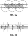
- a simple graphical example is provided in Fig. 3A , where each indicated "X" represents a luminaire that is illustrated as being at the center of an area being monitored. For the sake of simplicity, these areas are indicated as being circles. However, the invention is not so limited as terrain features, structures, trees, etc. would typically result in an asymmetric area.
- a decision is determined and depicted as various shaded mappings, with darker shading indicating a detected higher incidence of fog. The results are then overlaid as indicated in the figure.
- Fog positioning can be thus be inferred with confidence intervals. That is, the information illustrated in Fig. 3A would lead the system to infer which areas have higher or lower chances of fog. The result of this analysis is depicted in Fig. 3B .
- a series of time-stamped positing results would be compared. That is by way of example, detection results from a plurality of individual luminaires are combined such that the history of such results (e.g., time and location of luminaires involved) can be used to determine the direction of fog movement.
- the system is capable of determining both direction and speed of movement.
- a transmission mechanism is provided that is capable of alerting drivers who are in severe fog zones as well as those that are still in areas with lower or no fog whatsoever.
- the system is capable of knowing where the fog is located with varying levels of certainty and severity. It also knows the movement direction and speed of the mass of fog. With this information, coupled with the previously established max/min speeds of car traffic, the early-alert mechanism works by back-propagating the information to luminaires established in outside zones.
- this invention is capable of calculating how far to back-propagate the alert.
- This feature of the invention is depicted in Fig. 4 .
- one or more luminaires are equipped to communicate directly with passing cars, and/or this information can also be displayed through an alert on the driver's smartphone or other networked device.
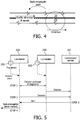
- Fig. 5 illustrates a flow chart of an embodiment of the invention.
- the luminaire 200 may communicate with neighboring luminaires or directly with the centralized server 102 (at step 2). Finally, the server 102 pinpoints the fog position and movement direction, and alerts the appropriate luminaire(s) (at step 3). At step 4, this alerted luminaire 200 can then back-propagate when needed, and send the alert to the passing drivers.
- processor, processing system, computer or computer system may represent one or more processing units in communication with one or more memory units and other devices, e.g., peripherals, connected electronically to and communicating with the at least one processing unit.
- the devices illustrated may be electronically connected to the one or more processing units via internal busses, e.g., serial, parallel, ISA bus, microchannel bus, PCI bus, PCMCIA bus, USB, etc., or one or more internal connections of a circuit, circuit card or other device, as well as portions and combinations of these and other communication media, or an external network, e.g., the Internet and Intranet.
- hardware circuitry may be used in place of, or in combination with, software instructions to implement the invention.
- the elements illustrated herein may also be implemented as discrete hardware elements or may be integrated into a single unit.
Description
- The present invention is directed generally to employing outdoor lighting networks (OLNs) to detect and provide information related to areas of reduced visibility, and in particular information related to fog conditions. More particularly, various inventive methods and apparatus disclosed herein relate to deploying fog sensors on luminaires in such OLNs to independently treat and consolidate the sensed data in a fault-tolerant manner. By communicating with neighboring luminaires and/or with a centralized server, fog positioning and direction of movement is identified. Further, the present invention provides a means to disseminate fog detections to thereby alert drivers who may be approaching the fog covered area.
-
KR 20090100174A - As is well known in the art, outdoor lighting poles are natural choices to place surveillance cameras to monitoring streets, parking lots, parks, and other outdoor areas. OLNs are thus used not only to control and manage outdoor lighting units, but to transmit data from cameras installed on lighting poles to monitoring centers. Further, the lighting units employed may also include lamps, video/image sensors, data storage, and communication and control modules that are connected with a centralized server directly or through other lighting units. Such an OLN system is described in co-pending patent application entitled "IMAGING SERVICE USING OUTDOOR LIGHTING NETWORKS" filed on September 22, 2011 in the US Patent and Trademark Office and afforded serial number
61/537945 - An example of a conventional
outdoor lighting network 100 is shown inFigure 1 . As illustrated therein light points or luminaires 108.1 -108.3 are in communication with anantenna tower 106 which, through anIP network 104, is in communication with a centralizedserver 102. It should be noted that various other means of communication are contemplated by the invention. These include power line communication or Radio Frequency (RF) mesh network of the light points. Further, the network connecting to the CentralizedServer 102 may be wired, wireless and/or cellular networks. Still further, The CentralizedServer 102 may also communicate with one or more light points directly if that light point is reachable through a cellular network. Still further, it is contemplated by the invention that the light points of the OLN may communicate directly with each other without requiring thetower structure 106 or the centralizedserver 102 depicted inFig. 1 . Such communication can be conducted by various means that are well-known in the art, to include wireless communication, wired communication (e.g., over power lines) and visual light communication. - The current invention relates to the field of intelligent sensor-enabled luminaires capable of sensing the physical world, performing diverse calculations and manipulation of the sensed data pertaining to fog detection, and transmitting information to processors, controllers and mobile devices. These would include nearby vehicles, autonomous devices (e.g., self-driving cars and unmanned aerial vehicles), or internet-connected mobile devices (e.g., smartphones and tablets), as well as centralized data warehouses with internet-based user interfaced applications. Particularly, the current invention relates to:
- 1. Testing and validating the input value obtained from the fog sensors, to allow for a more reliable input
- 2. Identifying fog positioning as well as the direction of movement (if it exists)
- 3. Alerting drivers and/or other autonomous devices of unsafe conditions due to fog.
- Unlike tornadoes or thunderstorms, fog is a somewhat passive weather phenomenon. Still, it's known to catch motorists by surprise. Fog tends to form on clear, cool nights when moist air accumulates slightly above the ground or water. This air is mixed during the night to form condensation, which dissipates as the sun rises. The extreme variability of fog, especially in its density and location, make it difficult for motorists to perceive and react quickly. Since light is refracted and deflected by the water droplets of the fog, this event is not at all limited to early mornings, and in fact can affect both day and night driving conditions.
- Fog is measured by visibility in miles, and is considered severe when visibility is 1/4 mile or less. The foggiest location in the United States is located at Cape Disappointment, Washington, with 106 severe fog days per year. On the east coast, it is the city of Eastport, Maine that takes the prize with 65 days. In inland areas, the foggiest location is Elkins, West Virginia with 81 days. By way of comparison, further south in Tampa Bay, Florida, the average is of 22 days. In northern Utah, super-cooled fog (< 32F) can persist in mountain valleys for weeks [http://ops.fhwa.dot.gov/weather/best_practices/CaseStudies/025.pdf].
- The often dramatic change in visibility, as well as the slowing of traffic, is what has led to many multi-car pileups with injuries and even deaths. Fog prediction, however, is no easy feat due to the variability in density, location, dissipation rates and area of coverage at a given point in time. Drivers who are most likely to be involved in fog-related crashes are residents of the neighboring counties - older than 20 but younger than 30 - driving during the morning commute hours and traveling on local and county roads in rural locations. Curiously, most fog-related crashes occur when the vehicle is traveling straight ahead.
- The general conclusion from the National Transportation Safety Board (NTSB) regarding investigations of major fog incidents was that they occurred because drivers did not maintain uniform reduced speeds during times of limited visibility. Sadly, maintaining uniform reduced speeds does not guarantee that a crash will be avoided.
- When fog does form, accurate real-time information on the presence and density is necessary for effective traffic control and initiation of safety measures. Currently, the National Oceanic and Atmospheric Administration (NOAA) Weather Wire Service collects all types of weather data and offers advisories. Unfortunately, this is still not enough to reduce the number of accidents. Generally, fixed message signs are used to identify fog-prone areas. However, since they represent the prevailing conditions only for a portion of the year, drivers may even ignore them. Therefore, they tend to be ineffective because the traveling public considers them to be irrelevant. Altogether, the principal form of fog detection continues to be the personal observation by the State police.
- Many states have formally deployed detection and warning systems, as well as integrated visibility/weather and motorist warning systems. Investments range from around $2-$4 million (see, e.g., http://www.cutr.usf.edu/research/fog.pdf and http://www.gtri.gatech.edu/casestudy/happy-motoring-safer-interstate-highway), and a complete solution (with visibility sensors, speed detectors, electronic signage and cameras to detect congestion) can reach upwards to the $12 million range (http://gs.flir.com/uploads/file/case-studies/case-study_caltrans-fog.pdf). The benefits of these systems, however, have not been clearly documented, and most states simple resort to driver awareness campaigns as the most cost-effective measure to reduce these types of crashes.
- The highest contributing factor to such high investment amounts appears to be the electronic signs and the required infrastructure to connect them (often in the $2+ million range). The fog sensing devices, on the other hand, are readily available at much more accessible prices. Forward scatter visibility sensors, for example, range from $5k to $8k per unit.
- Forward scatter technology measures the extinction coefficient-the sum of the absorption and scattering properties of light in the atmosphere. It does this by transmitting a narrow beam of light from a light-emitting diode (LED), which then scatters particles of light into a receiver. This receiver has an infrared detector that produces electrical energy equal to the amount of light received by the detector.
- The transmitter and receiver are aimed toward each other at an angle. If the air is clear, the transmitted infrared beam will pass by the receiver and no light will be detected. If the air becomes hazy or if precipitation is present, the beam will be scattered. The receiver will detect some of the scattered infrared light, proportional to the amount of haze or precipitation. The input to the receiver passes through an infrared filter to reduce the effects of other light. The sensors also incorporate several techniques that reduce the maintenance needed and ensure that the sensor remains reliable between maintenance visits (e.g., see http://tidesandcurrents.noaa.gov/publications/Technical Report NOS CO-OPS 055 .pdf).
- Assuming a fog-prone area is known, such forward scatter visibility sensors can be incorporated with and/or in communication with luminaires. Accordingly a cheaper alternative can be reached for fog warning systems, as long as a fault tolerant distributed system can be developed to interconnect the sensors and that reliable, high detection rates can be obtained.
- The current invention overcomes the problems in the prior art and provides cost savings while maintaining accuracy. Further, the current invention attains increased functionality with respect to communicating both raw data and fog analysis results.
- In various embodiments of the invention, a system is described which comprises the following components:
- 1. A smart lighting device capable of communicating with neighboring devices through various types of communication interfaces, to include wired, wireless and visual light communication means. Devices are also capable of store-and-forward, that is, they can receive data from neighbors, and at a later time forward that information on.
- 2. Smart lighting devices can communicate and inform nearby cars and autonomous devices of hazards. In addition, these may have applications that continuously poll a centralized server for data. The electronics in the car, for example, may choose to display the information for the driver, or take an action on its own, such as turn on the fog light, engage the all-wheel-drive, enable stability control, or emphasize maximum recommended driving speeds. An autonomous drone may increase its elevation and turn on warning LED's to signify a severe scenario. Finally, devices can also communicate with each other, forwarding data and exchanging information. In one embodiment, an individual vehicle has fog detection capability. When it detects fog, it transmits the information to one or more luminaires/poles using for instance dedicated short-range communications (DSRC) based radios, or even using the drivers' smartphone to connect to the internet. The Luminaires/poles then transmit the fog information to the central server and/or back propagate the alert to other vehicles in the vicinity of the vehicle so that they can take preventive actions to avoid a potential accident.
- 3. A fog sensor unit is attached to the lighting device. These sensors detect fog, albeit with possible failures. Many prior art sensors have measurement ranges from 33 feet to 20 miles, with accuracy in the ±10% range. In practice, however, fog-prone zones are densely monitored, so it can be safely assumed that such sensors are within the lower values of the range. In a further embodiment of the invention, some overlap exists between sensors to account for varying sensing ranges. In a still further embodiment, LED luminaires integrate fog sensing functionality by leveraging the self-embedded LED and processing power (e.g., to employ forward scatter technology).
- 4. A centralized server with processor(s) and database(s) where the data is sent, processed and stored.
- 5. Certain components of the lighting network (denominated gateways) may rely on fixed infrastructure (wireless LTE, WiMAX, or other wired mechanisms such as fiber optics) to communicate with the centralized server.
- 6. The centralized server has a detailed map of city; which may include GPS locations of luminaires, as well as direction of traffic (car) flow in each street, and max/min speed limits.
- In further embodiments of the invention, a method is described which comprises the following capabilities:
- 1. A data input treatment and validation mechanism that is capable of dealing with uncertainties due to sensor disparity, as well as sensor failures. This can be implemented as either a distributed mechanism (in that it is executed individually by a "smart" luminaire (as described below) and then communicated with neighboring devices), or a centralized mechanism (where all information is first routed to a centralized server);
- 2. A fog positioning and movement direction mechanism that is performed through a distributed aggregation protocol between neighboring luminaires;
- 3. A transmission protocol that is capable of alerting drivers who are in severe fog zones as well as those that are still in areas with lower or no fog whatsoever. This can occur between lighting devices and vehicles, between vehicles themselves, as well as from the centralized server to the vehicle.
- The advantages, nature, and various additional features of the invention will appear more fully upon consideration of the illustrative embodiments to be described in detail in connection with accompanying drawings wherein like reference numerals are used to identify like element throughout the drawings:
-
Figure 1 depicts a prior art outdoor lighting network. -
Figure 2 illustrates an exemplary smart luminaire of an embodiment of the present invention. -
Figures 3A and 3B illustrate obtained scanning results from multiple scanners and how this data is combined. -
Figure 4 illustrates the back propagation feature of an embodiment of the present invention. -
Figure 5 is a flowchart illustrating communication paths in various embodiments of the invention. - It is to be understood that these drawings are solely for purposes of illustrating the concepts of the invention and are not intended as a definition of the limits of the invention. It will be appreciated that the same reference numerals, possibly supplemented with reference characters, where appropriate, have been used throughout to identify corresponding parts.
- The following discussion of the invention will primarily be directed to fog detection. However, the invention is not so limited as the invention can be employed for other phenomenon in which visibility is affected -- in particular, visibility of drivers. These may include smog, smoke from fires, dust storms, dust/debris in proximity to a tornado vortex. In additional embodiments of the invention, light poles are equipped with flood sensors at their base. Once flooding is detected at a pole, that information could to forwarded to other poles and/or a centralized server. In this manner nearby poles could confirm direction of growth or movement of the flood affected area. Thus the present invention is capable of providing information related to weather phenomenon that can be used to alert governmental agencies as well as individuals and vehicles that are in or approaching the affected areas.
-
Fig. 2 illustrates an exemplarysmart luminaire 200 of the present invention. As illustrated, the luminaire comprises asensor 202 for attaining sensed values that are provided to adata analysis module 204. Amicroprocessor 206, which contains amemory 207, receives results attained by thedata analysis module 204. Themicroprocessor 206 provides information to a communication module which is capable of transmitted this information (as described below) via anantenna 106. Themicroprocessor 206 also controls theluminaire driver 210, which in the particular embodiment illustrated, includes anLED Module 211. As illustrated,luminaire 200 is also capable of receiving information viaantenna 106 which is received by thecommunication module 208 and provided to thedata analysis module 204 in making the decisions provided to themicroprocessor 206. - In the embodiment illustrated in
Fig. 2 , a "smart luminaire" is depicted. In additional embodiments of the invention, one or more luminaires may not contain all of these components or associated functionality. That is, a particular luminaire may only contain a sensor and a communication module; whereby at least some of the additional functionality described above may reside in another luminaire or in a management module. Alternatively, a particular luminaire may only contain a communication module, thereby enabling a communication link between modules. Thus, it is envisioned that a distributed functionality exists whereby the features described above may be implemented in one or more various components of the system. - Each
sensor device 202 continuously senses fog environmental data and outputs a value which measures how "foggy" the environment is. As noted above, the actual criterion being measured is how visibly obstructed one's view is that is due to various environment factors. The term "foggy" will hence be used to collectively refer to the level of that obstruction. - Without lack of generality, the following discussion assumes that this value is numeric. Two things may be associated with that value: 1) the sensor may be faulty or needing maintenance. Therefore, the luminaire needs to be able to identify this scenario; 2) since luminaires are placed in different geographical locations, different neighboring devices may very likely identify different numerical values.
- It should be noted that two events are identified because the solution to the former often relies on the communication and aggregation of measured values from nearby neighbors. Existing methods can take the average, mean, or use additional statistical analysis to reach a "single value" from the combination of many sensors. However, due to the extreme variability of fog, this is no easy feat. In fact, if it existed, current solutions would have shown drastic reduction in levels of accidents. Reports indicate that technologies probably cannot provide effective solutions if problematic locations are dispersed and scattered. Cheaper, distributed solutions, such as those described herein with respect to the present invention, would be much more effective. That is, the current invention discloses a process to better facilitate the validation of the measured values, through a mechanism that embraces uncertainty and subjectivity. In the following described embodiment of the invention, this is obtained through a 2-step process:
- Linguistic classes of fog levels are first defined. For example, "no fog", "low visibility", "severe", "very dangerous" and so forth. These are pre-defined and associated with ranges of values by a fog expert beforehand. If the measured value from a fog sensor is within the range of any of the classes, then it is said to "belong" to the class with a certain amount of membership. This is actually a mapping that transforms the numerical single value into a tuple of values containing the class, and a percentage of membership. The combination of all percentage values should equal to 100%. What this means is that, the subjective perception of the fog sensor will be completely defined by the sum of all membership classes. Consequently, in the present invention, classes should overlap, and will contain both single elements as well as combination of elements.
- By way of example, assuming that there are 2 linguistic classes defined {"no fog", "some fog"}. The membership classes would then contain the single elements {"no fog"} and {"some fog"}, as well as the combination elements {"no fog" + "some fog"}. The final set of classes used during the mapping step will allow for 3 different options, which are: {"no fog", "no fog" + "some fog", "some fog"}.
- At the end of
step 1, each individual luminaire will have its own set of tuples <class, membership> which will most likely vary from one to the other. Thus by way of example, "membership" may be expressed as a percentage. Accordingly, a luminaire may arrive at the conclusion of: [no fog, 2%], [some fog, 60%]. It is also likely that a luminaire may determine after this mapping step, that it belongs to multiple classes with high membership levels. This is acceptable and even welcomed. While this introduces uncertainty, it also resembles how human perception works - very subjective and depending on multitude of factors. - According to the present invention, for the decision phase the luminaire will behave differently depending on whether it has neighboring luminaires to which it is capable of communicating with or not. In one embodiment, luminaires can detect whether they have neighbors by listening to periodical "HELLO" messages sent, and/or as told by the centralized server. Once this is determined:
- a) If the luminaire does not have any neighbors, then it will decide on the class with the highest membership. This is a simple comparison between classes. If two (or more) classes have the same membership, the class chosen should always prefer combination elements.
- b) If the luminaire has neighbors, then it executes a supplemental step -- and will merge its decision with that of its neighbors based on any number of Evidential Reasoning algorithms previously published. By way of example such publications include: G. Shafer, A mathematical theory of evidence. Princeton university press, 1976; B. Marhic, L. Delahoche, C. Soleau, A.-M. Jolly-Desodt, and D. Menga, "Detection of abnormal sensor behaviour using tbm," in Proceedings of the Workshop on the Theory of Belief Function, 2010; and H. Wu, M. Siegel, and M. Siegel, "Sensor fusion using dempster-shafer theory," in Proceedings of IEEE Instrumentation and Measurement Technology Conference, pp. 21-23, 2002. What these algorithms allow for is the capability of merging different tuples while being able to handle contradictions. For example, any of these algorithms would allow the merging of a luminaire that is 90% sure that "no fog" occurred with a luminaire that is "90%" that "severe fog" occurred. At the end of this step, each luminaire would have contacted its neighbors and obtained, besides their individual decision, a final merged perception tuple of <class, memberships
- At this point in time, each individual luminaire will have either a single decision (2a above) or a single decision and a merged perception (2b). This information is saved in the luminaires' memory, where a history of time-based decisions and perceptions can be analyzed. In additional embodiments of the invention, this information is also transmitted to the centralized server through the available gateway. By looking at the history, a luminaire (or the centralized server) can identify individual luminaire fog-sensor related failures, as well as reach a localized consensus on the fog-detection event. At the end of
step 2, each luminaire will have a single decision which linguistically measures it's perception of the fog environmental data. - In an embodiment of the present invention, single linguistic decisions are analyzed from each luminaire; and, by analyzing the decisions of all luminaires within a certain area; the fog position, any recent changes in its size, and its direction of movement is identified. The analysis can be done either in a centralized manner - by transmitting all decisions to the centralized server, or through a distributed manner - by nodes reaching a localized consensus using group membership protocols. Without loss of generality, examples related to the centralized solution are provided below.
- In this embodiment, a centralized server is provided wherein the centralized server possesses the following information:
- a) The exact location of the luminaries. This could have been obtained in the commissioning phase, for example, by using handheld GPS-enabled devices and later stored in an accessible database. In addition, the location of luminaires could be determined through localization techniques applied within the OLN or by means of GPS devices installed in the luminaires themselves.
- b) A mapping of GPS locations to streets, and capacity of identifying sequences of luminaires. That is, that a certain luminaire comes before or after another, and which luminaires are neighbors of one another.
- c) The direction of traffic flow on each street.
- Each luminaire will transmit to the centralized server its decision (obtained in the phase described above). The centralized server will then execute a conflict resolution and merging mechanism that also relies on, e.g., Evidential Reasoning on groups of neighboring nodes. The position is determined by a step-wise merging of the decisions from neighboring luminaires. A simple graphical example is provided in
Fig. 3A , where each indicated "X" represents a luminaire that is illustrated as being at the center of an area being monitored. For the sake of simplicity, these areas are indicated as being circles. However, the invention is not so limited as terrain features, structures, trees, etc. would typically result in an asymmetric area. Within each area, a decision is determined and depicted as various shaded mappings, with darker shading indicating a detected higher incidence of fog. The results are then overlaid as indicated in the figure. - Fog positioning can be thus be inferred with confidence intervals. That is, the information illustrated in
Fig. 3A would lead the system to infer which areas have higher or lower chances of fog. The result of this analysis is depicted inFig. 3B . - To determine the direction of fog movement, a series of time-stamped positing results would be compared. That is by way of example, detection results from a plurality of individual luminaires are combined such that the history of such results (e.g., time and location of luminaires involved) can be used to determine the direction of fog movement. By analyzing the direction (or lack thereof) of how each inferred area changes, the system is capable of determining both direction and speed of movement.
- In a further embodiment of the invention, a transmission mechanism is provided that is capable of alerting drivers who are in severe fog zones as well as those that are still in areas with lower or no fog whatsoever.
- With the information obtained from the previous two phases, the system is capable of knowing where the fog is located with varying levels of certainty and severity. It also knows the movement direction and speed of the mass of fog. With this information, coupled with the previously established max/min speeds of car traffic, the early-alert mechanism works by back-propagating the information to luminaires established in outside zones.
- Given the fog direction and speed, and given the traffic direction and speed, this invention is capable of calculating how far to back-propagate the alert. This feature of the invention is depicted in
Fig. 4 . In various embodiments of the invention, one or more luminaires are equipped to communicate directly with passing cars, and/or this information can also be displayed through an alert on the driver's smartphone or other networked device. -
Fig. 5 illustrates a flow chart of an embodiment of the invention. Once a luminaire receives the value from thefog sensor 202,step 1 is executed and a decision is made. - Depending on locality factors, the
luminaire 200 may communicate with neighboring luminaires or directly with the centralized server 102 (at step 2). Finally, theserver 102 pinpoints the fog position and movement direction, and alerts the appropriate luminaire(s) (at step 3). At step 4, this alertedluminaire 200 can then back-propagate when needed, and send the alert to the passing drivers. - As one skilled in the art would recognize, the terms processor, processing system, computer or computer system may represent one or more processing units in communication with one or more memory units and other devices, e.g., peripherals, connected electronically to and communicating with the at least one processing unit. Furthermore, the devices illustrated may be electronically connected to the one or more processing units via internal busses, e.g., serial, parallel, ISA bus, microchannel bus, PCI bus, PCMCIA bus, USB, etc., or one or more internal connections of a circuit, circuit card or other device, as well as portions and combinations of these and other communication media, or an external network, e.g., the Internet and Intranet. In other embodiments, hardware circuitry may be used in place of, or in combination with, software instructions to implement the invention. For example, the elements illustrated herein may also be implemented as discrete hardware elements or may be integrated into a single unit.
- While there has been shown, described, and pointed out fundamental novel features of the present invention as applied to preferred embodiments thereof, it will be understood that various omissions and substitutions and changes in the apparatus described, in the form and details of the devices disclosed, and in their operation, may be made by those skilled in the art without departing from the present invention. It is expressly intended that all combinations of those elements that perform substantially the same function in substantially the same way to achieve the same results are within the scope of the invention. Substitutions of elements from one described embodiment to another are also fully intended and contemplated. For example, any numerical values presented herein are considered only exemplary and are presented to provide examples of the subject matter claimed as the invention.
- Hence, the invention, as recited in the appended claims, is not limited by the numerical examples provided herein.
Claims (15)
- A method for providing visibility alerts by transmitting information related to a fog covered area in which visibility is affected, said method comprising:monitoring a geographical area by each of a plurality of visibility detectors (202);receiving, at each of a plurality of lighting units (200) of at least one Outdoor Lighting Network, monitoring data from at least one of said visibility detectors (202), wherein at least two of said lighting units (200) are in communication with each other;deriving a consolidated estimate of visibility conditions pertaining to a combined geographical area defined by the monitored geographical areas associated with two or more of said visibility detectors (202);the method characterised bydetermining a position, direction and speed of said fog covered area from the consolidated estimate of visibility conditions; andtransmitting information comprising the position, direction and speed of said fog covered area.
- The method of claim 1 wherein said deriving step comprises mapping from data received from each visibility detector (202) to a set of tuples; wherein said tuples comprises membership classes that are associated with levels of obscured visibility.
- The method of claim 2 wherein said tuples comprises a percentage membership associated with each class.
- The method of claim 1 further comprising storing the following information on one or more databases accessible by a centralized server (102):a geographical location of each of the lighting devices (200) and its associated at least one visibility detector (202);a mapping of street locations associated with the lighting devices (200); anda direction and legal speed limit of traffic flow pertaining to the mapped street locations.
- The method of claim 4 further comprising providing an early alert to drivers and to autonomous vehicles and devices approaching the fog covered area.
- The method of claim 5 wherein said providing step comprises:
determining one or more street locations where vehicles in said locations are approaching the fog covered area. - A system for providing information related to a fog covered area in which visibility is affected, said system comprising:at least one Outdoor Lighting Network (OLN) comprising a plurality of lighting units (200), at least two of which being in communication with each other;a plurality of visibility detectors (202), each in communication with at least one of said lighting devices (200), and each capable of monitoring a geographical area;a data analysis engine (204) for receiving monitoring data from two or more of said visibility detectors (202) and for deriving a consolidated estimate of visibility conditions pertaining to a combined geographical area defined by the monitored geographical areas associated with two or more of said visibility detectors (202);the system characterised by comprisingmeans for determining a position, direction and speed of said fog covered area from the consolidated estimate of visibility conditions; and,a communication module (208) for transmitting information comprising the position, direction and speed of said fog covered area.
- The system of claim 7 wherein said data analysis engine (204) comprises a means for mapping from data received from each visibility detector (202) to a set of tuples; wherein said tuples comprises membership classes that are associated with levels of obscured visibility.
- The system of claim 8 wherein said data analysis engine resides in a centralized server (102); and wherein tuples from a plurality of light units are utilized in deriving the consolidated estimate.
- The system of claim 8 wherein said data analysis engine (204) resides in a first light unit (200), the first light unit (200) being in communication with a least one neighboring light unit (200) which monitors at least part of the same geographical area as that being monitored by the first light unit (200);
wherein an estimate derived by the first light unit (200) pertaining to the geographical area being monitored by the first light unit (200) is merged with one or more estimates obtained by said at least one neighboring light unit (200). - The system of claim 8 wherein said data analysis engine (204) resides in a first light unit (200), the first light unit (200) not being in communication with a neighboring light unit (200) which monitors at least part of the same geographical area as that being monitored by the first light unit (200);
wherein an estimate of visibility conditions pertaining to the geographical area being monitored by the first light unit (200) is derived by the first light unit (200) based on highest membership within the membership classes. - The system of claim 7 further comprising:a centralized server (102); and,one or more databases, said databases comprising the following information:a geographical location of each of the lighting devices (200) and its associated at least one visibility detector (202);a mapping of street locations associated with the lighting devices (200); anda direction and legal speed limit of traffic flow pertaining to the mapped street locations.
- The system of claim 12 further comprising a means for providing an early alert to drivers approaching the fog covered area.
- The system of claim 13 wherein the means for providing an early alert are selected from the group consisting of:communication means for communicating with a hand-held communication device of the driver;communication means for communicating by one or more light units directly with the driver's vehicle;communication means for communicating from the centralized server to the driver's vehicle;communication means for communicating between vehicles themselves; andmeans for determining one or more street locations where vehicles in said locations are approaching the fog covered area.
- A computer program product comprising a plurality of program code portions, stored in a non-transitory computer readable medium, for carrying out the method according to claim 1.
Applications Claiming Priority (2)
| Application Number | Priority Date | Filing Date | Title |
|---|---|---|---|
| US201361839472P | 2013-06-26 | 2013-06-26 | |
| PCT/IB2014/062005 WO2014207592A2 (en) | 2013-06-26 | 2014-06-06 | An apparatus and method employing sensor-based luminaires to detect areas of reduced visibility and their direction of movement |
Publications (2)
| Publication Number | Publication Date |
|---|---|
| EP3014248A2 EP3014248A2 (en) | 2016-05-04 |
| EP3014248B1 true EP3014248B1 (en) | 2020-08-05 |
Family
ID=51022379
Family Applications (1)
| Application Number | Title | Priority Date | Filing Date |
|---|---|---|---|
| EP14733368.6A Revoked EP3014248B1 (en) | 2013-06-26 | 2014-06-06 | An apparatus and method employing sensor-based luminaires to detect areas of reduced visibility and their direction of movement |
Country Status (5)
| Country | Link |
|---|---|
| US (1) | US9542841B2 (en) |
| EP (1) | EP3014248B1 (en) |
| JP (1) | JP6466428B2 (en) |
| CN (1) | CN105324661B (en) |
| WO (1) | WO2014207592A2 (en) |
Families Citing this family (13)
| Publication number | Priority date | Publication date | Assignee | Title |
|---|---|---|---|---|
| WO2015151055A1 (en) | 2014-04-04 | 2015-10-08 | Koninklijke Philips N.V. | System and methods to support autonomous vehicles via environmental perception and sensor calibration and verification |
| US10613186B2 (en) * | 2015-11-30 | 2020-04-07 | Signify Holding B.V. | Distinguishing devices having positions and directions |
| CN107274695B (en) * | 2016-04-08 | 2020-10-27 | 上海三思电子工程有限公司 | Intelligent lighting system, intelligent vehicle and vehicle driving assisting system and method thereof |
| JP2019519051A (en) * | 2016-04-07 | 2019-07-04 | 上海三思▲電▼子工程有限公司Shanghai Sansi Electronic Engineering Co.,Ltd. | Intelligent lighting system, lighting device, vehicle, in-vehicle terminal, vehicle driving support system, and vehicle driving support method |
| JP6986076B2 (en) | 2016-09-22 | 2021-12-22 | シグニファイ ホールディング ビー ヴィSignify Holding B.V. | Flood location and notification via intelligent lighting |
| EP3607538B1 (en) | 2017-04-06 | 2023-10-25 | Signify Holding B.V. | Lighting system and method of controlling a lighting system |
| KR102224997B1 (en) * | 2017-12-11 | 2021-03-09 | 현대모비스 주식회사 | Safety tripod |
| US11385338B2 (en) * | 2019-03-06 | 2022-07-12 | Cnh Industrial America Llc | System and method for disregarding obscured sensor data during the performance of an agricultural operation |
| WO2020210334A1 (en) * | 2019-04-12 | 2020-10-15 | Continental Automotive Systems, Inc. | Warning system for a vehicle during bad weather and poor visibility |
| WO2020210338A1 (en) * | 2019-04-12 | 2020-10-15 | Continental Automotive Systems, Inc. | Early warning system for a vehicle during poor light conditions |
| CN111526629B (en) * | 2020-06-28 | 2021-07-06 | 华南理工大学 | Color temperature control method of tunnel LED lighting system |
| CN115116252A (en) * | 2022-08-30 | 2022-09-27 | 四川九通智路科技有限公司 | Method, device and system for guiding vehicle safely |
| CN117042252B (en) * | 2023-10-08 | 2023-12-05 | 深圳华唐锐照明电器有限公司 | Intelligent lamp control system based on optics and radar perception |
Citations (7)
| Publication number | Priority date | Publication date | Assignee | Title |
|---|---|---|---|---|
| JP2001281352A (en) | 2000-04-03 | 2001-10-10 | Mitsubishi Electric Corp | Fog observation system |
| KR100946749B1 (en) | 2008-03-19 | 2010-03-11 | 정양권 | The Methord and the System of the fog detection using the Image recognition and image learning methord |
| KR100963849B1 (en) | 2008-07-15 | 2010-06-16 | (주)미라클산업 | Method of providing road weather information and system thereof |
| KR20120030178A (en) | 2010-09-17 | 2012-03-28 | 주식회사 동호 | Apparatus of fog reduction on road and bridge by water roof formation and the method thereof |
| CN102682495A (en) | 2011-02-18 | 2012-09-19 | 福特全球技术公司 | Computer-implemented method of gathering data |
| WO2012140152A1 (en) | 2011-04-12 | 2012-10-18 | Aleksander Gerbec | Network comprising nodes associated with outdoor lighting devices |
| WO2012172470A1 (en) | 2011-06-13 | 2012-12-20 | Koninklijke Philips Electronics N.V. | Adaptive controlled outdoor lighting system and method of operation thereof |
Family Cites Families (14)
| Publication number | Priority date | Publication date | Assignee | Title |
|---|---|---|---|---|
| US6889009B2 (en) * | 2001-04-16 | 2005-05-03 | Lightpointe Communications, Inc. | Integrated environmental control and management system for free-space optical communication systems |
| ATE346984T1 (en) | 2002-10-03 | 2006-12-15 | Maria Spunda | FOG WARNING AND GUIDING DEVICE |
| CN2648761Y (en) | 2003-09-17 | 2004-10-13 | 石珂 | Arrangement for transmitting expressway fog light detection and control signal |
| ITTO20030770A1 (en) | 2003-10-02 | 2005-04-03 | Fiat Ricerche | LONG-DETECTION DETECTOR LONG ONE |
| JP4730267B2 (en) * | 2006-07-04 | 2011-07-20 | 株式会社デンソー | Visibility state determination device for vehicle |
| JP2008234489A (en) * | 2007-03-22 | 2008-10-02 | Toshiba Lighting & Technology Corp | Traffic congestion informing system |
| JP4604103B2 (en) * | 2008-03-31 | 2010-12-22 | トヨタ自動車株式会社 | Intersection line-of-sight detection device |
| US8143811B2 (en) | 2008-06-25 | 2012-03-27 | Lumetric, Inc. | Lighting control system and method |
| KR101013578B1 (en) | 2009-02-18 | 2011-02-14 | 김종헌 | Operation System of Fog Warning Light Using LED |
| CN201412765Y (en) * | 2009-05-27 | 2010-02-24 | 福建省交通科学技术研究所 | Solar energy fog area automatic detection controller and wireless fog lamp |
| TW201220952A (en) * | 2010-03-29 | 2012-05-16 | Koninkl Philips Electronics Nv | Network of heterogeneous devices including at least one outdoor lighting fixture node |
| FR2965354B1 (en) | 2010-09-28 | 2012-10-12 | France Etat Ponts Chaussees | METHOD AND DEVICE FOR DETECTING FOG, NIGHT |
| CN103959910B (en) * | 2011-09-22 | 2016-11-09 | 皇家飞利浦有限公司 | Utilize the radiography service of outdoor lighting network |
| CN102622892A (en) * | 2012-04-01 | 2012-08-01 | 南京理工大学 | Automatic fog condition detection and alarm system and method for expressway |
-
2014
- 2014-06-06 WO PCT/IB2014/062005 patent/WO2014207592A2/en active Application Filing
- 2014-06-06 US US14/900,216 patent/US9542841B2/en active Active
- 2014-06-06 JP JP2016522899A patent/JP6466428B2/en active Active
- 2014-06-06 CN CN201480036292.2A patent/CN105324661B/en active Active
- 2014-06-06 EP EP14733368.6A patent/EP3014248B1/en not_active Revoked
Patent Citations (7)
| Publication number | Priority date | Publication date | Assignee | Title |
|---|---|---|---|---|
| JP2001281352A (en) | 2000-04-03 | 2001-10-10 | Mitsubishi Electric Corp | Fog observation system |
| KR100946749B1 (en) | 2008-03-19 | 2010-03-11 | 정양권 | The Methord and the System of the fog detection using the Image recognition and image learning methord |
| KR100963849B1 (en) | 2008-07-15 | 2010-06-16 | (주)미라클산업 | Method of providing road weather information and system thereof |
| KR20120030178A (en) | 2010-09-17 | 2012-03-28 | 주식회사 동호 | Apparatus of fog reduction on road and bridge by water roof formation and the method thereof |
| CN102682495A (en) | 2011-02-18 | 2012-09-19 | 福特全球技术公司 | Computer-implemented method of gathering data |
| WO2012140152A1 (en) | 2011-04-12 | 2012-10-18 | Aleksander Gerbec | Network comprising nodes associated with outdoor lighting devices |
| WO2012172470A1 (en) | 2011-06-13 | 2012-12-20 | Koninklijke Philips Electronics N.V. | Adaptive controlled outdoor lighting system and method of operation thereof |
Also Published As
| Publication number | Publication date |
|---|---|
| JP6466428B2 (en) | 2019-02-06 |
| US20160148506A1 (en) | 2016-05-26 |
| JP2016528601A (en) | 2016-09-15 |
| WO2014207592A9 (en) | 2015-03-26 |
| CN105324661A (en) | 2016-02-10 |
| US9542841B2 (en) | 2017-01-10 |
| WO2014207592A3 (en) | 2015-05-14 |
| CN105324661B (en) | 2019-07-05 |
| EP3014248A2 (en) | 2016-05-04 |
| WO2014207592A2 (en) | 2014-12-31 |
Similar Documents
| Publication | Publication Date | Title |
|---|---|---|
| EP3014248B1 (en) | An apparatus and method employing sensor-based luminaires to detect areas of reduced visibility and their direction of movement | |
| CN212160931U (en) | ETC-X system for vehicle-road cooperation | |
| CN108983806B (en) | Method and system for generating area detection and air route planning data and aircraft | |
| CN111724616B (en) | Method and device for acquiring and sharing data based on artificial intelligence | |
| CN113706737B (en) | Road surface inspection system and method based on automatic driving vehicle | |
| EP3416147B1 (en) | Method for providing drowsiness alerts in vehicles | |
| EP3361412B1 (en) | Black ice detection system, program, and method | |
| CN113870553B (en) | Road network running state detection system and method for mixed traffic flow | |
| US11495064B2 (en) | Value-anticipating cooperative perception with an intelligent transportation system station | |
| CN113327415A (en) | Method, apparatus, device, storage medium and system for distributing traffic information | |
| Abdel-Aty et al. | Synthesis of visibility detection systems. | |
| Almeida et al. | Trust: Transportation and road monitoring system for ubiquitous real-time information services | |
| KR20230166855A (en) | Antenna monitoring and selection | |
| FR3052418B1 (en) | METHOD AND DEVICE FOR ASSISTING THE DRIVING OF A VEHICLE CIRCULATING ON THE APPROACH OF A CARREFOUR | |
| Ahmed et al. | Synthesis of state-of-the-art in visibility detection systems’ applications and research | |
| JP2023530069A (en) | Roadside detection and warning system and method | |
| Kaur et al. | Smart vehicle system for road safety during foggy weather | |
| Nejjari et al. | Event traffic detection using heterogenous wireless sensors network | |
| CN114067553A (en) | Traffic condition notification system and method | |
| Singh et al. | A framework for early detection of incident in dense traffic using vehicular ad-hoc networks | |
| JP7404643B2 (en) | Vehicle communication management device, vehicle communication management system, vehicle communication management method, and vehicle communication management program | |
| Agrawal et al. | Automated Traffic Monitoring Control for Improved Visibility On Curve Hilly Road Using Internet-of-Things | |
| KR102592142B1 (en) | Speed violation control system of variable speed limit zone | |
| WO2023155218A1 (en) | A system and a method for reducing false alerts in a road management system | |
| CN209822025U (en) | Road and driving real-time monitoring management system |
Legal Events
| Date | Code | Title | Description |
|---|---|---|---|
| PUAI | Public reference made under article 153(3) epc to a published international application that has entered the european phase |
Free format text: ORIGINAL CODE: 0009012 |
|
| 17P | Request for examination filed |
Effective date: 20160126 |
|
| AK | Designated contracting states |
Kind code of ref document: A2 Designated state(s): AL AT BE BG CH CY CZ DE DK EE ES FI FR GB GR HR HU IE IS IT LI LT LU LV MC MK MT NL NO PL PT RO RS SE SI SK SM TR |
|
| AX | Request for extension of the european patent |
Extension state: BA ME |
|
| RAP1 | Party data changed (applicant data changed or rights of an application transferred) |
Owner name: PHILIPS LIGHTING HOLDING B.V. |
|
| DAX | Request for extension of the european patent (deleted) | ||
| RIN1 | Information on inventor provided before grant (corrected) |
Inventor name: WANG, JIANFENG Inventor name: CAVALCANTI, DAVE ALBERTO TAVARES Inventor name: OLIVEIRA, TALMAI BRANDAO DE |
|
| STAA | Information on the status of an ep patent application or granted ep patent |
Free format text: STATUS: EXAMINATION IS IN PROGRESS |
|
| 17Q | First examination report despatched |
Effective date: 20170907 |
|
| RAP1 | Party data changed (applicant data changed or rights of an application transferred) |
Owner name: PHILIPS LIGHTING HOLDING B.V. |
|
| RAP1 | Party data changed (applicant data changed or rights of an application transferred) |
Owner name: SIGNIFY HOLDING B.V. |
|
| GRAP | Despatch of communication of intention to grant a patent |
Free format text: ORIGINAL CODE: EPIDOSNIGR1 |
|
| STAA | Information on the status of an ep patent application or granted ep patent |
Free format text: STATUS: GRANT OF PATENT IS INTENDED |
|
| INTG | Intention to grant announced |
Effective date: 20200226 |
|
| RIN1 | Information on inventor provided before grant (corrected) |
Inventor name: CAVALCANTI, DAVE ALBERTO TAVARES Inventor name: OLIVEIRA, TALMAI BRANDAO DE Inventor name: WANG, JIANFENG |
|
| GRAS | Grant fee paid |
Free format text: ORIGINAL CODE: EPIDOSNIGR3 |
|
| GRAA | (expected) grant |
Free format text: ORIGINAL CODE: 0009210 |
|
| STAA | Information on the status of an ep patent application or granted ep patent |
Free format text: STATUS: THE PATENT HAS BEEN GRANTED |
|
| AK | Designated contracting states |
Kind code of ref document: B1 Designated state(s): AL AT BE BG CH CY CZ DE DK EE ES FI FR GB GR HR HU IE IS IT LI LT LU LV MC MK MT NL NO PL PT RO RS SE SI SK SM TR |
|
| REG | Reference to a national code |
Ref country code: GB Ref legal event code: FG4D |
|
| REG | Reference to a national code |
Ref country code: CH Ref legal event code: EP |
|
| REG | Reference to a national code |
Ref country code: AT Ref legal event code: REF Ref document number: 1299403 Country of ref document: AT Kind code of ref document: T Effective date: 20200815 |
|
| REG | Reference to a national code |
Ref country code: DE Ref legal event code: R096 Ref document number: 602014068561 Country of ref document: DE |
|
| REG | Reference to a national code |
Ref country code: IE Ref legal event code: FG4D |
|
| REG | Reference to a national code |
Ref country code: NO Ref legal event code: T2 Effective date: 20200805 |
|
| REG | Reference to a national code |
Ref country code: SE Ref legal event code: TRGR |
|
| REG | Reference to a national code |
Ref country code: LT Ref legal event code: MG4D |
|
| REG | Reference to a national code |
Ref country code: NL Ref legal event code: MP Effective date: 20200805 |
|
| PG25 | Lapsed in a contracting state [announced via postgrant information from national office to epo] |
Ref country code: LT Free format text: LAPSE BECAUSE OF FAILURE TO SUBMIT A TRANSLATION OF THE DESCRIPTION OR TO PAY THE FEE WITHIN THE PRESCRIBED TIME-LIMIT Effective date: 20200805 Ref country code: FI Free format text: LAPSE BECAUSE OF FAILURE TO SUBMIT A TRANSLATION OF THE DESCRIPTION OR TO PAY THE FEE WITHIN THE PRESCRIBED TIME-LIMIT Effective date: 20200805 Ref country code: GR Free format text: LAPSE BECAUSE OF FAILURE TO SUBMIT A TRANSLATION OF THE DESCRIPTION OR TO PAY THE FEE WITHIN THE PRESCRIBED TIME-LIMIT Effective date: 20201106 Ref country code: BG Free format text: LAPSE BECAUSE OF FAILURE TO SUBMIT A TRANSLATION OF THE DESCRIPTION OR TO PAY THE FEE WITHIN THE PRESCRIBED TIME-LIMIT Effective date: 20201105 Ref country code: ES Free format text: LAPSE BECAUSE OF FAILURE TO SUBMIT A TRANSLATION OF THE DESCRIPTION OR TO PAY THE FEE WITHIN THE PRESCRIBED TIME-LIMIT Effective date: 20200805 Ref country code: PT Free format text: LAPSE BECAUSE OF FAILURE TO SUBMIT A TRANSLATION OF THE DESCRIPTION OR TO PAY THE FEE WITHIN THE PRESCRIBED TIME-LIMIT Effective date: 20201207 Ref country code: HR Free format text: LAPSE BECAUSE OF FAILURE TO SUBMIT A TRANSLATION OF THE DESCRIPTION OR TO PAY THE FEE WITHIN THE PRESCRIBED TIME-LIMIT Effective date: 20200805 |
|
| PG25 | Lapsed in a contracting state [announced via postgrant information from national office to epo] |
Ref country code: RS Free format text: LAPSE BECAUSE OF FAILURE TO SUBMIT A TRANSLATION OF THE DESCRIPTION OR TO PAY THE FEE WITHIN THE PRESCRIBED TIME-LIMIT Effective date: 20200805 Ref country code: PL Free format text: LAPSE BECAUSE OF FAILURE TO SUBMIT A TRANSLATION OF THE DESCRIPTION OR TO PAY THE FEE WITHIN THE PRESCRIBED TIME-LIMIT Effective date: 20200805 Ref country code: LV Free format text: LAPSE BECAUSE OF FAILURE TO SUBMIT A TRANSLATION OF THE DESCRIPTION OR TO PAY THE FEE WITHIN THE PRESCRIBED TIME-LIMIT Effective date: 20200805 Ref country code: NL Free format text: LAPSE BECAUSE OF FAILURE TO SUBMIT A TRANSLATION OF THE DESCRIPTION OR TO PAY THE FEE WITHIN THE PRESCRIBED TIME-LIMIT Effective date: 20200805 Ref country code: IS Free format text: LAPSE BECAUSE OF FAILURE TO SUBMIT A TRANSLATION OF THE DESCRIPTION OR TO PAY THE FEE WITHIN THE PRESCRIBED TIME-LIMIT Effective date: 20201205 |
|
| PG25 | Lapsed in a contracting state [announced via postgrant information from national office to epo] |
Ref country code: SM Free format text: LAPSE BECAUSE OF FAILURE TO SUBMIT A TRANSLATION OF THE DESCRIPTION OR TO PAY THE FEE WITHIN THE PRESCRIBED TIME-LIMIT Effective date: 20200805 Ref country code: RO Free format text: LAPSE BECAUSE OF FAILURE TO SUBMIT A TRANSLATION OF THE DESCRIPTION OR TO PAY THE FEE WITHIN THE PRESCRIBED TIME-LIMIT Effective date: 20200805 Ref country code: DK Free format text: LAPSE BECAUSE OF FAILURE TO SUBMIT A TRANSLATION OF THE DESCRIPTION OR TO PAY THE FEE WITHIN THE PRESCRIBED TIME-LIMIT Effective date: 20200805 Ref country code: EE Free format text: LAPSE BECAUSE OF FAILURE TO SUBMIT A TRANSLATION OF THE DESCRIPTION OR TO PAY THE FEE WITHIN THE PRESCRIBED TIME-LIMIT Effective date: 20200805 Ref country code: CZ Free format text: LAPSE BECAUSE OF FAILURE TO SUBMIT A TRANSLATION OF THE DESCRIPTION OR TO PAY THE FEE WITHIN THE PRESCRIBED TIME-LIMIT Effective date: 20200805 |
|
| REG | Reference to a national code |
Ref country code: DE Ref legal event code: R026 Ref document number: 602014068561 Country of ref document: DE |
|
| PLBI | Opposition filed |
Free format text: ORIGINAL CODE: 0009260 |
|
| PLAX | Notice of opposition and request to file observation + time limit sent |
Free format text: ORIGINAL CODE: EPIDOSNOBS2 |
|
| PG25 | Lapsed in a contracting state [announced via postgrant information from national office to epo] |
Ref country code: AL Free format text: LAPSE BECAUSE OF FAILURE TO SUBMIT A TRANSLATION OF THE DESCRIPTION OR TO PAY THE FEE WITHIN THE PRESCRIBED TIME-LIMIT Effective date: 20200805 |
|
| 26 | Opposition filed |
Opponent name: SCHOEPF, PATRICK Effective date: 20210505 |
|
| PG25 | Lapsed in a contracting state [announced via postgrant information from national office to epo] |
Ref country code: SK Free format text: LAPSE BECAUSE OF FAILURE TO SUBMIT A TRANSLATION OF THE DESCRIPTION OR TO PAY THE FEE WITHIN THE PRESCRIBED TIME-LIMIT Effective date: 20200805 |
|
| PG25 | Lapsed in a contracting state [announced via postgrant information from national office to epo] |
Ref country code: IT Free format text: LAPSE BECAUSE OF FAILURE TO SUBMIT A TRANSLATION OF THE DESCRIPTION OR TO PAY THE FEE WITHIN THE PRESCRIBED TIME-LIMIT Effective date: 20200805 |
|
| PG25 | Lapsed in a contracting state [announced via postgrant information from national office to epo] |
Ref country code: SI Free format text: LAPSE BECAUSE OF FAILURE TO SUBMIT A TRANSLATION OF THE DESCRIPTION OR TO PAY THE FEE WITHIN THE PRESCRIBED TIME-LIMIT Effective date: 20200805 |
|
| PLBB | Reply of patent proprietor to notice(s) of opposition received |
Free format text: ORIGINAL CODE: EPIDOSNOBS3 |
|
| PG25 | Lapsed in a contracting state [announced via postgrant information from national office to epo] |
Ref country code: MC Free format text: LAPSE BECAUSE OF FAILURE TO SUBMIT A TRANSLATION OF THE DESCRIPTION OR TO PAY THE FEE WITHIN THE PRESCRIBED TIME-LIMIT Effective date: 20200805 |
|
| REG | Reference to a national code |
Ref country code: CH Ref legal event code: PL |
|
| REG | Reference to a national code |
Ref country code: BE Ref legal event code: MM Effective date: 20210630 |
|
| PG25 | Lapsed in a contracting state [announced via postgrant information from national office to epo] |
Ref country code: LU Free format text: LAPSE BECAUSE OF NON-PAYMENT OF DUE FEES Effective date: 20210606 |
|
| PG25 | Lapsed in a contracting state [announced via postgrant information from national office to epo] |
Ref country code: LI Free format text: LAPSE BECAUSE OF NON-PAYMENT OF DUE FEES Effective date: 20210630 Ref country code: IE Free format text: LAPSE BECAUSE OF NON-PAYMENT OF DUE FEES Effective date: 20210606 Ref country code: CH Free format text: LAPSE BECAUSE OF NON-PAYMENT OF DUE FEES Effective date: 20210630 |
|
| REG | Reference to a national code |
Ref country code: DE Ref legal event code: R103 Ref document number: 602014068561 Country of ref document: DE Ref country code: DE Ref legal event code: R064 Ref document number: 602014068561 Country of ref document: DE |
|
| PG25 | Lapsed in a contracting state [announced via postgrant information from national office to epo] |
Ref country code: BE Free format text: LAPSE BECAUSE OF NON-PAYMENT OF DUE FEES Effective date: 20210630 |
|
| PGFP | Annual fee paid to national office [announced via postgrant information from national office to epo] |
Ref country code: SE Payment date: 20220622 Year of fee payment: 9 Ref country code: NO Payment date: 20220617 Year of fee payment: 9 Ref country code: GB Payment date: 20220621 Year of fee payment: 9 |
|
| REG | Reference to a national code |
Ref country code: AT Ref legal event code: UEP Ref document number: 1299403 Country of ref document: AT Kind code of ref document: T Effective date: 20200805 |
|
| PGFP | Annual fee paid to national office [announced via postgrant information from national office to epo] |
Ref country code: AT Payment date: 20220621 Year of fee payment: 9 |
|
| PGFP | Annual fee paid to national office [announced via postgrant information from national office to epo] |
Ref country code: FR Payment date: 20220623 Year of fee payment: 9 |
|
| PGFP | Annual fee paid to national office [announced via postgrant information from national office to epo] |
Ref country code: DE Payment date: 20220628 Year of fee payment: 9 |
|
| RDAF | Communication despatched that patent is revoked |
Free format text: ORIGINAL CODE: EPIDOSNREV1 |
|
| RDAG | Patent revoked |
Free format text: ORIGINAL CODE: 0009271 |
|
| STAA | Information on the status of an ep patent application or granted ep patent |
Free format text: STATUS: PATENT REVOKED |
|
| REG | Reference to a national code |
Ref country code: CH Ref legal event code: PL |
|
| 27W | Patent revoked |
Effective date: 20220705 |
|
| GBPR | Gb: patent revoked under art. 102 of the ep convention designating the uk as contracting state |
Effective date: 20220705 |
|
| REG | Reference to a national code |
Ref country code: NO Ref legal event code: MMEP |
|
| REG | Reference to a national code |
Ref country code: AT Ref legal event code: MA03 Ref document number: 1299403 Country of ref document: AT Kind code of ref document: T Effective date: 20220705 |
|
| PG25 | Lapsed in a contracting state [announced via postgrant information from national office to epo] |
Ref country code: CY Free format text: LAPSE BECAUSE OF FAILURE TO SUBMIT A TRANSLATION OF THE DESCRIPTION OR TO PAY THE FEE WITHIN THE PRESCRIBED TIME-LIMIT Effective date: 20200805 |
|
| REG | Reference to a national code |
Ref country code: SE Ref legal event code: ECNC |
|
| PG25 | Lapsed in a contracting state [announced via postgrant information from national office to epo] |
Ref country code: HU Free format text: LAPSE BECAUSE OF FAILURE TO SUBMIT A TRANSLATION OF THE DESCRIPTION OR TO PAY THE FEE WITHIN THE PRESCRIBED TIME-LIMIT; INVALID AB INITIO Effective date: 20140606 |