EP3014137B1 - Brake cylinder - Google Patents
Brake cylinder Download PDFInfo
- Publication number
- EP3014137B1 EP3014137B1 EP13735195.3A EP13735195A EP3014137B1 EP 3014137 B1 EP3014137 B1 EP 3014137B1 EP 13735195 A EP13735195 A EP 13735195A EP 3014137 B1 EP3014137 B1 EP 3014137B1
- Authority
- EP
- European Patent Office
- Prior art keywords
- rib
- brake cylinder
- base wall
- front cover
- elevated portion
- Prior art date
- Legal status (The legal status is an assumption and is not a legal conclusion. Google has not performed a legal analysis and makes no representation as to the accuracy of the status listed.)
- Active
Links
Images



Classifications
-
- F—MECHANICAL ENGINEERING; LIGHTING; HEATING; WEAPONS; BLASTING
- F16—ENGINEERING ELEMENTS AND UNITS; GENERAL MEASURES FOR PRODUCING AND MAINTAINING EFFECTIVE FUNCTIONING OF MACHINES OR INSTALLATIONS; THERMAL INSULATION IN GENERAL
- F16D—COUPLINGS FOR TRANSMITTING ROTATION; CLUTCHES; BRAKES
- F16D55/00—Brakes with substantially-radial braking surfaces pressed together in axial direction, e.g. disc brakes
- F16D55/02—Brakes with substantially-radial braking surfaces pressed together in axial direction, e.g. disc brakes with axially-movable discs or pads pressed against axially-located rotating members
- F16D55/22—Brakes with substantially-radial braking surfaces pressed together in axial direction, e.g. disc brakes with axially-movable discs or pads pressed against axially-located rotating members by clamping an axially-located rotating disc between movable braking members, e.g. movable brake discs or brake pads
- F16D55/224—Brakes with substantially-radial braking surfaces pressed together in axial direction, e.g. disc brakes with axially-movable discs or pads pressed against axially-located rotating members by clamping an axially-located rotating disc between movable braking members, e.g. movable brake discs or brake pads with a common actuating member for the braking members
- F16D55/2245—Brakes with substantially-radial braking surfaces pressed together in axial direction, e.g. disc brakes with axially-movable discs or pads pressed against axially-located rotating members by clamping an axially-located rotating disc between movable braking members, e.g. movable brake discs or brake pads with a common actuating member for the braking members in which the common actuating member acts on two levers carrying the braking members, e.g. tong-type brakes
-
- F—MECHANICAL ENGINEERING; LIGHTING; HEATING; WEAPONS; BLASTING
- F16—ENGINEERING ELEMENTS AND UNITS; GENERAL MEASURES FOR PRODUCING AND MAINTAINING EFFECTIVE FUNCTIONING OF MACHINES OR INSTALLATIONS; THERMAL INSULATION IN GENERAL
- F16D—COUPLINGS FOR TRANSMITTING ROTATION; CLUTCHES; BRAKES
- F16D65/00—Parts or details
- F16D65/0006—Noise or vibration control
-
- F—MECHANICAL ENGINEERING; LIGHTING; HEATING; WEAPONS; BLASTING
- F16—ENGINEERING ELEMENTS AND UNITS; GENERAL MEASURES FOR PRODUCING AND MAINTAINING EFFECTIVE FUNCTIONING OF MACHINES OR INSTALLATIONS; THERMAL INSULATION IN GENERAL
- F16D—COUPLINGS FOR TRANSMITTING ROTATION; CLUTCHES; BRAKES
- F16D65/00—Parts or details
- F16D65/14—Actuating mechanisms for brakes; Means for initiating operation at a predetermined position
- F16D65/28—Actuating mechanisms for brakes; Means for initiating operation at a predetermined position arranged apart from the brake
-
- F—MECHANICAL ENGINEERING; LIGHTING; HEATING; WEAPONS; BLASTING
- F16—ENGINEERING ELEMENTS AND UNITS; GENERAL MEASURES FOR PRODUCING AND MAINTAINING EFFECTIVE FUNCTIONING OF MACHINES OR INSTALLATIONS; THERMAL INSULATION IN GENERAL
- F16D—COUPLINGS FOR TRANSMITTING ROTATION; CLUTCHES; BRAKES
- F16D2121/00—Type of actuator operation force
- F16D2121/02—Fluid pressure
- F16D2121/08—Fluid pressure acting on a membrane-type actuator, e.g. for gas pressure
-
- F—MECHANICAL ENGINEERING; LIGHTING; HEATING; WEAPONS; BLASTING
- F16—ENGINEERING ELEMENTS AND UNITS; GENERAL MEASURES FOR PRODUCING AND MAINTAINING EFFECTIVE FUNCTIONING OF MACHINES OR INSTALLATIONS; THERMAL INSULATION IN GENERAL
- F16D—COUPLINGS FOR TRANSMITTING ROTATION; CLUTCHES; BRAKES
- F16D2125/00—Components of actuators
- F16D2125/02—Fluid-pressure mechanisms
- F16D2125/04—Cylinders
Definitions
- the present invention relates to brake cylinders for air-operated brakes and, in particular to brake cylinders for air-operated disc brakes for commercial vehicles.
- the invention further relates to air-operated brakes.
- Pneumatically disc brakes on commercial vehicles are well-known.
- a housing of a brake cylinder is attached to a housing of a brake calliper and applies a brake actuation force through a cylinder plunger to a lever within the calliper.
- the housing of the brake cylinder is divided at least in two parts, namely front cover and a bottom. Both parts are generally cup-shaped wherein the front cover is attached to the brake calliper.
- the front cover has a cylindrical lateral surface and a base wall adjoining the lateral surface, with a circumferential edge as a transition from the lateral surface to the base wall.
- the latter is provided with an elevated portion having a central bore for the cylinder plunger.
- the base wall with the elevated portion is designed symmetrically as could be seen from a top view.
- the material of the front cover has a thickness due to forces acting on the front cover and resulting from the function of the brake cylinder.
- Document DE 44 69 351 A1 shows a brake cylinder according to the preamble of claim 1.
- the front cover has a rib extending on the base wall and beside the elevated portion.
- the rib could be placed anywhere on the base wall in addition to the elevated portion and could be directed somewhere.
- the rib increases vibration resistance of front cover or brake cylinder, durability against vibrations and overall stiffness by shape. Hence the same stiffness as before (without a rib) could be achieved with a reduced thickness of the front cover having a rib.
- the rib extends from the elevated portion in the direction of a circumferential edge between the base wall and the cylindrical lateral surface. Particularly the rib ends at the circumferential edge.
- An upper surface of the elevated portion can be provided at the same level as an adjoining end of upper surface of the rib. Especially there is no gap or disruption between said upper surfaces.
- the rib extends from the elevated portion in a radial direction, the rib particularly extends perpendicularly to the elevated portion.
- the rib is starting from a medium area of the elevated portion. Also possible is a perpendicular alignment without being directed radially.
- the rib extends in a radial direction and ends at the cylindrical lateral surface or at a circumferential edge between the base wall and the cylindrical lateral surface.
- the rib extends from the elevated portion and inclines down to the base wall, the rib particularly inclines down to an intersection of the base wall with the cylindrical surface. Said intersection can be the circumferential edge.
- the rib connects the circumferential edge with the elevated portion.
- the circumferential edge or any other edge of the front cover could be rounded or bevelled.
- the rib is provided with a width smaller than the width of the elevated portion.
- Part of the invention is also a pneumatically actuable brake with a brake cylinder as mentioned before.
- a pneumatically operated brake cylinder 10 as an actuator for disc brakes on commercial vehicles.
- the brake cylinder 10 has a cup-shaped front cover 11, a cylindrical middle section 12 and a cup-shaped bottom part 13.
- Front cover 11 has an annular flange 14. The latter is hold on a corresponding flange (not shown) of the middle section 12 by a circumferential retaining clamp 15.
- a cylindrical lateral surface 16 Adjoining the flange 14 a cylindrical lateral surface 16 is provided. Lying opposite to the flange 14 the lateral surface 16 has a bevelled or rounded circumferential edge 17 as a transition to a base wall 18, the latter extending substantially perpendicularly to the lateral surface 16.
- the base wall 18 has an elevated portion 19 having a central wall 20 with two outer openings 21, 22 and one middle opening 23.
- a plunger 24 is mounted in the brake cylinder 10 for reciprocation within the middle opening 23. Threaded studs or bushings 25, 26 extend through openings 21, 22.
- the central wall 20 is attached to a brake calliper (not shown) of a disc brake.
- the central wall 20 is designed like an isosceles trapezium and its reflection, with the middle opening 23 and obtuse angles 27, 28 crossed by an axis of reflection 29 between the trapeziums.
- Longitudinal edges 30, 31, 32, 33 are provided between the obtuse angles 27, 28 and transversal edges 34, 35.
- Angles 36, 37, 38, 39 are provided between the longitudinal edges 30 - 33 and the transversal edges 34, 35.
- Base wall 18 and central wall 20 are parallel to each other. Longitudinal side walls 40, 41, 42, 43 and front walls 44, 45 raise from the base wall 18 up to the central wall 20. Transition from the base wall 18 to the side walls 40 - 43 and front walls 44, 45 on one hand and from the central wall 20 to the side walls 40 - 43 and front walls 44, 45 on the other hand are rounded or bevelled.
- a rib 46 is provided on the base wall 18, connecting the central wall 20 with the circumferential edge 17.
- the rib 46 is directed in the axis of reflection 29 and also radially with respect to the middle opening 23 and is designed like a ramp or wedge with an oblique top side 47, and triangular side walls 48, 49. Transition to adjoining walls are again bevelled or rounded.
- the top side 47 is an extension of the central wall 20 but oriented obliquely downwards to the circumferential edge 17.
- the front cover 11 Due to the reinforcing rib 46 the front cover 11 has an increased vibration resistance together with an increased stiffness compared to a front cover without rib. It is further possible to reduce the wall thickness of the front cover 11 together with a reduction of weight and cost.
- the front cover 11 including the rib 46 is for example made of metal sheet, aluminum, composite or composite with metal core by deep-drawing or thermoforming. Hence the rib 46 is a three-dimensional portion or section of the front cover 11 and is open on one side as well as the elevated portion 19.
- the front cover would have two axes of symmetry. Provided with the rib 46 only one axis of symmetry is left, see line IVa-IVb in Fig. 2 .
- the circumferential edge 17 could be provided with dents 50, 51, 52 or any other dished sections.
- Fig. 2 and 3 show the dent 50 in front of or radially outside of the side wall 42 and the longitudinal edge 32, while the dent 51 is positioned in front of the other side wall 41.
- the dent 52 is shown in front of the angle 39, the latter adjoining the side wall 41 with longitudinal edge 33.
- Dents 51, 52 are close together and even overlap each other.
- An overlapping portion 53 is situated slightly inwards compared to the surface of the circumferential edge 17 but is looking like a protrusion between the dents 51, 52.
- All dents 50 to 52 are on one side of the base wall 18 away from the rib 46.
- Each dent 50 to 52 extends over an angle 54 of approximately 20° or 25° or 15° to 30°.
- Each dent 51, 52 is broader than dent 50.
- the dents 50 to 52 not only increase the asymmetry of front cover but also enable or ease fastening of front cover 11 to different brake callipers (not shown).
Landscapes
- Engineering & Computer Science (AREA)
- General Engineering & Computer Science (AREA)
- Mechanical Engineering (AREA)
- Braking Arrangements (AREA)
Description
- The present invention relates to brake cylinders for air-operated brakes and, in particular to brake cylinders for air-operated disc brakes for commercial vehicles. The invention further relates to air-operated brakes.
- Pneumatically disc brakes on commercial vehicles are well-known. In a pneumatically disc brake a housing of a brake cylinder is attached to a housing of a brake calliper and applies a brake actuation force through a cylinder plunger to a lever within the calliper.
- The housing of the brake cylinder is divided at least in two parts, namely front cover and a bottom. Both parts are generally cup-shaped wherein the front cover is attached to the brake calliper.
- The front cover has a cylindrical lateral surface and a base wall adjoining the lateral surface, with a circumferential edge as a transition from the lateral surface to the base wall. The latter is provided with an elevated portion having a central bore for the cylinder plunger. Generally, the base wall with the elevated portion is designed symmetrically as could be seen from a top view. The material of the front cover has a thickness due to forces acting on the front cover and resulting from the function of the brake cylinder.
- Since braking a wheel nearly always causes vibrations the front cover could be vibrating too due to unfavorable conditions. As a result lifetime of brake cylinder could decrease.
-
Document DE 44 69 351 A1 shows a brake cylinder according to the preamble of claim 1. - It is an object of the invention to overcome the foregoing problems and to provide a brake cylinder with a thinner material of front cover and/or with a less vibrating front cover.
- This object is achieved by providing a brake cylinder with the features of claim 1. The front cover has a rib extending on the base wall and beside the elevated portion. The rib could be placed anywhere on the base wall in addition to the elevated portion and could be directed somewhere. The rib increases vibration resistance of front cover or brake cylinder, durability against vibrations and overall stiffness by shape. Hence the same stiffness as before (without a rib) could be achieved with a reduced thickness of the front cover having a rib.
- In one aspect of the invention, the rib extends from the elevated portion in the direction of a circumferential edge between the base wall and the cylindrical lateral surface. Particularly the rib ends at the circumferential edge. An upper surface of the elevated portion can be provided at the same level as an adjoining end of upper surface of the rib. Especially there is no gap or disruption between said upper surfaces.
- In a further aspect of the invention, the rib extends from the elevated portion in a radial direction, the rib particularly extends perpendicularly to the elevated portion. In a radial and perpendicular alignment the rib is starting from a medium area of the elevated portion. Also possible is a perpendicular alignment without being directed radially.
- In a further aspect of the invention, the rib extends in a radial direction and ends at the cylindrical lateral surface or at a circumferential edge between the base wall and the cylindrical lateral surface.
- In a further aspect of the invention, the rib extends from the elevated portion and inclines down to the base wall, the rib particularly inclines down to an intersection of the base wall with the cylindrical surface. Said intersection can be the circumferential edge. The rib connects the circumferential edge with the elevated portion. The circumferential edge or any other edge of the front cover could be rounded or bevelled.
- In a further aspect of the invention, the rib is provided with a width smaller than the width of the elevated portion.
- Part of the invention is also a pneumatically actuable brake with a brake cylinder as mentioned before.
- Further objects, advantages and novel features of the present invention will become apparent from the following detailed description of the invention together with the accompanying drawings and from the claims.
- Fig. 1
- is a three-dimensional view of an air-operated brake cylinder;
- Fig. 2
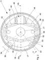
- is a plan view of a front cover of the brake cylinder;
- Fig. 3
- is a three-dimensional view of the front cover;
- Fig. 4
- is a cross-sectional view of the front cover taken along lines IVa-IVb of
Fig. 2 ; - Fig. 5
- is a cross-sectional view of the front cover taken along lines V-IVb of
Fig. 2 . - Referring to
Fig. 1 , there is shown a pneumatically operatedbrake cylinder 10 as an actuator for disc brakes on commercial vehicles. Thebrake cylinder 10 has a cup-shaped front cover 11, acylindrical middle section 12 and a cup-shaped bottom part 13.Front cover 11 has anannular flange 14. The latter is hold on a corresponding flange (not shown) of themiddle section 12 by acircumferential retaining clamp 15. - Adjoining the flange 14 a cylindrical
lateral surface 16 is provided. Lying opposite to theflange 14 thelateral surface 16 has a bevelled or roundedcircumferential edge 17 as a transition to abase wall 18, the latter extending substantially perpendicularly to thelateral surface 16. - The
base wall 18 has an elevatedportion 19 having acentral wall 20 with twoouter openings plunger 24 is mounted in thebrake cylinder 10 for reciprocation within themiddle opening 23. Threaded studs orbushings openings central wall 20 is attached to a brake calliper (not shown) of a disc brake. - The
central wall 20 is designed like an isosceles trapezium and its reflection, with the middle opening 23 andobtuse angles Longitudinal edges obtuse angles transversal edges Angles transversal edges -
Base wall 18 andcentral wall 20 are parallel to each other.Longitudinal side walls front walls base wall 18 up to thecentral wall 20. Transition from thebase wall 18 to the side walls 40 - 43 andfront walls central wall 20 to the side walls 40 - 43 andfront walls - A
rib 46 is provided on thebase wall 18, connecting thecentral wall 20 with thecircumferential edge 17. Therib 46 is directed in the axis of reflection 29 and also radially with respect to the middle opening 23 and is designed like a ramp or wedge with an obliquetop side 47, andtriangular side walls top side 47 is an extension of thecentral wall 20 but oriented obliquely downwards to thecircumferential edge 17. - Due to the reinforcing
rib 46 thefront cover 11 has an increased vibration resistance together with an increased stiffness compared to a front cover without rib. It is further possible to reduce the wall thickness of thefront cover 11 together with a reduction of weight and cost. - The
front cover 11 including therib 46 is for example made of metal sheet, aluminum, composite or composite with metal core by deep-drawing or thermoforming. Hence therib 46 is a three-dimensional portion or section of thefront cover 11 and is open on one side as well as theelevated portion 19. - Without the
rib 46 the front cover would have two axes of symmetry. Provided with therib 46 only one axis of symmetry is left, see line IVa-IVb inFig. 2 . To achieve a more asymmetrical design for a higher stiffness and increased vibration resistance thecircumferential edge 17 could be provided withdents Fig. 2 and3 show thedent 50 in front of or radially outside of theside wall 42 and thelongitudinal edge 32, while thedent 51 is positioned in front of theother side wall 41. Thedent 52 is shown in front of theangle 39, the latter adjoining theside wall 41 withlongitudinal edge 33. -
Dents portion 53 is situated slightly inwards compared to the surface of thecircumferential edge 17 but is looking like a protrusion between thedents base wall 18 away from therib 46. Eachdent 50 to 52 extends over anangle 54 of approximately 20° or 25° or 15° to 30°. Eachdent dent 50. Thedents 50 to 52 not only increase the asymmetry of front cover but also enable or ease fastening offront cover 11 to different brake callipers (not shown).Reference numerals 10 brake cylinder 39 angle 11 front cover 40 side wall 12 middle section 41 side wall 13 bottom part 42 side wall 14 flange 43 side wall 15 retaining clamp 44 front wall 16 lateral surface 45 front wall 17 circumferential edge 46 rib 18 base wall 47 top side 19 elevated portion 48 side wall 20 central wall 49 side wall 21 outer opening 50 dent 22 outer opening 51 dent 23 middle opening 52 dent 24 plunger 53 overlapping portion 25 bushing 26 bushing 27 obtuse angle 28 obtuse angle 29 axis of reflection 30 longitudinal edge 31 longitudinal edge 32 longitudinal edge 33 longitudinal edge 34 transversal edge 35 transversal edge 36 angle 37 angle 38 angle
Claims (7)
- Brake cylinder for an air-operated brake, with a housing including a front cover (11), wherein the front cover (11) is provided with a generally cylindrical lateral surface (16) and with a base wall (18) adjoining the lateral surface (16), wherein the base wall (18) is provided with an elevated portion (19) having a central bore or middle opening (23) for a cylinder plunger, characterised in that the front cover (11) is provided with a rib (46), the rib (46) extends on the base wall (18) in addition to the elevated portion (19).
- A brake cylinder according to claim 1, wherein the rib (46) extends from the elevated portion (19) in the direction of a circumferential edge (17) between the base wall (18) and the cylindrical lateral surface (16).
- A brake cylinder according to claim 1 or 2, wherein the rib (46) extends from the elevated portion (19) in a radial direction, the rib (46) particularly extends perpendicularly to the elevated portion (19).
- A brake cylinder according to one of claims 1 to 3, wherein the rib (46) extends in a radial direction and ends at the cylindrical lateral surface (16) or at a circumferential edge (17) between the base wall (18) and the cylindrical lateral surface (16).
- A brake cylinder according to one of claims 1 to 4, wherein the rib (46) extends from the elevated portion and inclines down to the base wall (18), the rib (46) particularly inclines down to an intersection of the base wall (18) with the cylindrical lateral surface (16).
- A brake cylinder according to one of claims 1 to 5, wherein the rib (46) has a width smaller than the elevated portion (19).
- Pneumatically actuable brake, particularly a disc brake, with a brake cylinder according to one of claims 1 to 6.
Applications Claiming Priority (1)
| Application Number | Priority Date | Filing Date | Title |
|---|---|---|---|
| PCT/EP2013/001900 WO2014206430A1 (en) | 2013-06-28 | 2013-06-28 | Brake cylinder |
Publications (2)
| Publication Number | Publication Date |
|---|---|
| EP3014137A1 EP3014137A1 (en) | 2016-05-04 |
| EP3014137B1 true EP3014137B1 (en) | 2017-06-14 |
Family
ID=48782267
Family Applications (1)
| Application Number | Title | Priority Date | Filing Date |
|---|---|---|---|
| EP13735195.3A Active EP3014137B1 (en) | 2013-06-28 | 2013-06-28 | Brake cylinder |
Country Status (4)
| Country | Link |
|---|---|
| US (1) | US10197118B2 (en) |
| EP (1) | EP3014137B1 (en) |
| CN (1) | CN105143703B (en) |
| WO (1) | WO2014206430A1 (en) |
Families Citing this family (2)
| Publication number | Priority date | Publication date | Assignee | Title |
|---|---|---|---|---|
| DE102015001944A1 (en) * | 2015-02-16 | 2016-08-18 | Lucas Automotive Gmbh | Vacuum brake booster with stiffened housing |
| US11965567B2 (en) * | 2018-05-29 | 2024-04-23 | Hitachi Astemo, Ltd. | Disc brake |
Family Cites Families (18)
| Publication number | Priority date | Publication date | Assignee | Title |
|---|---|---|---|---|
| BE456303A (en) * | 1943-06-21 | |||
| US3462986A (en) * | 1967-10-26 | 1969-08-26 | Rockwell Standard Co | Brake actuator |
| DE1920559C3 (en) * | 1969-04-23 | 1974-05-22 | Wabco Westinghouse Gmbh, 3000 Hannover-Linden | Diaphragm cylinder for actuating devices operated with a pressure medium |
| GB1317744A (en) * | 1970-07-04 | 1973-05-23 | Girling Ltd | Disc brakes |
| GB1390531A (en) * | 1972-03-01 | 1975-04-16 | Girling Ltd | Brake actuator units |
| GB1460280A (en) * | 1973-05-11 | 1976-12-31 | Dewandre Co Ltd C | Brake actuating mechanisms |
| JP2552043Y2 (en) * | 1991-01-17 | 1997-10-27 | 日信工業 株式会社 | Negative pressure booster |
| DE4409351B4 (en) | 1994-03-18 | 2007-08-30 | Knorr-Bremse Systeme für Nutzfahrzeuge GmbH | Device for monitoring the piston stroke of a pneumatically actuated brake cylinder |
| EP0796814B1 (en) * | 1996-03-22 | 2004-09-22 | Sanyo Kogyo Co., Ltd. | Brake for hoist gear |
| US6318240B1 (en) * | 1998-01-29 | 2001-11-20 | Indian Head Industries, Inc. | Brake actuator |
| SE517122C2 (en) * | 1999-10-18 | 2002-04-16 | Haldex Brake Prod Ab | Låsaktuator |
| DE10004094C1 (en) * | 2000-01-31 | 2001-08-16 | Knorr Bremse Systeme | Cover for brake cylinder of goods vehicle has several closed blind holes with the base member of at least one selected opening removable to produce ventilation opening |
| DE10148480A1 (en) * | 2001-10-01 | 2003-04-17 | Knorr Bremse Systeme | Parking brake device and method for actuating the parking brake |
| DE10163144B4 (en) | 2001-12-20 | 2008-04-24 | Knorr-Bremse Systeme für Nutzfahrzeuge GmbH | Parking brake device and control method |
| DE202005018886U1 (en) * | 2005-12-02 | 2006-02-02 | Knorr-Bremse Systeme für Nutzfahrzeuge GmbH | Combined service brake and spring brake cylinder with internal ventilation |
| JP2009173082A (en) * | 2008-01-22 | 2009-08-06 | Hitachi Ltd | Brake device |
| JP5363388B2 (en) * | 2010-03-23 | 2013-12-11 | 本田技研工業株式会社 | Brake panel structure of drum brake |
| US9050958B2 (en) * | 2012-06-11 | 2015-06-09 | Tse Brakes, Inc. | Pneumatic brake actuator chamber with rotationally positionable housing |
-
2013
- 2013-06-28 EP EP13735195.3A patent/EP3014137B1/en active Active
- 2013-06-28 WO PCT/EP2013/001900 patent/WO2014206430A1/en not_active Ceased
- 2013-06-28 US US14/900,187 patent/US10197118B2/en active Active
- 2013-06-28 CN CN201380075874.7A patent/CN105143703B/en active Active
Non-Patent Citations (1)
| Title |
|---|
| None * |
Also Published As
| Publication number | Publication date |
|---|---|
| WO2014206430A1 (en) | 2014-12-31 |
| EP3014137A1 (en) | 2016-05-04 |
| CN105143703A (en) | 2015-12-09 |
| CN105143703B (en) | 2018-02-06 |
| US10197118B2 (en) | 2019-02-05 |
| US20160146274A1 (en) | 2016-05-26 |
Similar Documents
| Publication | Publication Date | Title |
|---|---|---|
| US8505699B2 (en) | Flanged shim for disc brake squeal attenuation | |
| US20170102042A1 (en) | A spring of a caliper of a disc brake | |
| US11162550B2 (en) | Caliper for opposed piston type disc brake | |
| WO2017033899A1 (en) | Cylindrical elastic coupling device for axle arms | |
| JP2006520449A (en) | Disc brake with brake lining guided on bolts | |
| KR20230134986A (en) | Brake caliper for vehicle and manufaturing method therof | |
| US20180094681A1 (en) | Polymeric brake piston with reinforcing core | |
| US10197118B2 (en) | Brake cylinder | |
| KR20150076790A (en) | Disc brake device combined parking brake with different materials | |
| US6298954B1 (en) | Brake calliper, in particular for motor vehicles | |
| US20070034457A1 (en) | Disk brake system for automobile | |
| CN109690117B (en) | Disc brake caliper | |
| JP2006057852A (en) | Drum with ventilation system and brake including such a drum | |
| US20230287944A1 (en) | Brake piston for a vehicle disc brake assembly having inner groove for structural noise dampening | |
| TW201413130A (en) | Brake backing plate with step-chamfer | |
| US20180245648A1 (en) | Disc brake and piston | |
| US20170067523A1 (en) | Brake piston head for a disk brake device, brake piston and disk brake device | |
| ITPD20120214A1 (en) | BRAKE CALIPER WITH DISC | |
| JP4461082B2 (en) | Caliper body for disc brakes for vehicles | |
| US8919502B2 (en) | Cord assembly for replacement of outer beam and carrier including the same | |
| US20160319892A1 (en) | Pre-split Composite Brake Drum with Steel Bands | |
| US20210190157A1 (en) | Lining carrier for a disc brake | |
| JP7047917B2 (en) | Brake disc mounting structure for railway vehicles and brake disc units using this | |
| KR102595873B1 (en) | Multiple layer pad for disc brake | |
| US20180149217A1 (en) | Drum Brake Dust Shield for a Vehicle Braking System |
Legal Events
| Date | Code | Title | Description |
|---|---|---|---|
| PUAI | Public reference made under article 153(3) epc to a published international application that has entered the european phase |
Free format text: ORIGINAL CODE: 0009012 |
|
| 17P | Request for examination filed |
Effective date: 20160128 |
|
| AK | Designated contracting states |
Kind code of ref document: A1 Designated state(s): AL AT BE BG CH CY CZ DE DK EE ES FI FR GB GR HR HU IE IS IT LI LT LU LV MC MK MT NL NO PL PT RO RS SE SI SK SM TR |
|
| AX | Request for extension of the european patent |
Extension state: BA ME |
|
| DAX | Request for extension of the european patent (deleted) | ||
| GRAP | Despatch of communication of intention to grant a patent |
Free format text: ORIGINAL CODE: EPIDOSNIGR1 |
|
| INTG | Intention to grant announced |
Effective date: 20170314 |
|
| GRAS | Grant fee paid |
Free format text: ORIGINAL CODE: EPIDOSNIGR3 |
|
| GRAA | (expected) grant |
Free format text: ORIGINAL CODE: 0009210 |
|
| AK | Designated contracting states |
Kind code of ref document: B1 Designated state(s): AL AT BE BG CH CY CZ DE DK EE ES FI FR GB GR HR HU IE IS IT LI LT LU LV MC MK MT NL NO PL PT RO RS SE SI SK SM TR |
|
| REG | Reference to a national code |
Ref country code: GB Ref legal event code: FG4D |
|
| REG | Reference to a national code |
Ref country code: CH Ref legal event code: EP Ref country code: AT Ref legal event code: REF Ref document number: 901290 Country of ref document: AT Kind code of ref document: T Effective date: 20170615 |
|
| REG | Reference to a national code |
Ref country code: IE Ref legal event code: FG4D |
|
| REG | Reference to a national code |
Ref country code: FR Ref legal event code: PLFP Year of fee payment: 5 |
|
| REG | Reference to a national code |
Ref country code: DE Ref legal event code: R096 Ref document number: 602013022261 Country of ref document: DE |
|
| REG | Reference to a national code |
Ref country code: SE Ref legal event code: TRGR |
|
| REG | Reference to a national code |
Ref country code: NL Ref legal event code: MP Effective date: 20170614 |
|
| REG | Reference to a national code |
Ref country code: LT Ref legal event code: MG4D |
|
| PG25 | Lapsed in a contracting state [announced via postgrant information from national office to epo] |
Ref country code: NO Free format text: LAPSE BECAUSE OF FAILURE TO SUBMIT A TRANSLATION OF THE DESCRIPTION OR TO PAY THE FEE WITHIN THE PRESCRIBED TIME-LIMIT Effective date: 20170914 Ref country code: GR Free format text: LAPSE BECAUSE OF FAILURE TO SUBMIT A TRANSLATION OF THE DESCRIPTION OR TO PAY THE FEE WITHIN THE PRESCRIBED TIME-LIMIT Effective date: 20170915 Ref country code: LT Free format text: LAPSE BECAUSE OF FAILURE TO SUBMIT A TRANSLATION OF THE DESCRIPTION OR TO PAY THE FEE WITHIN THE PRESCRIBED TIME-LIMIT Effective date: 20170614 Ref country code: FI Free format text: LAPSE BECAUSE OF FAILURE TO SUBMIT A TRANSLATION OF THE DESCRIPTION OR TO PAY THE FEE WITHIN THE PRESCRIBED TIME-LIMIT Effective date: 20170614 Ref country code: HR Free format text: LAPSE BECAUSE OF FAILURE TO SUBMIT A TRANSLATION OF THE DESCRIPTION OR TO PAY THE FEE WITHIN THE PRESCRIBED TIME-LIMIT Effective date: 20170614 |
|
| REG | Reference to a national code |
Ref country code: AT Ref legal event code: MK05 Ref document number: 901290 Country of ref document: AT Kind code of ref document: T Effective date: 20170614 |
|
| PG25 | Lapsed in a contracting state [announced via postgrant information from national office to epo] |
Ref country code: NL Free format text: LAPSE BECAUSE OF FAILURE TO SUBMIT A TRANSLATION OF THE DESCRIPTION OR TO PAY THE FEE WITHIN THE PRESCRIBED TIME-LIMIT Effective date: 20170614 Ref country code: RS Free format text: LAPSE BECAUSE OF FAILURE TO SUBMIT A TRANSLATION OF THE DESCRIPTION OR TO PAY THE FEE WITHIN THE PRESCRIBED TIME-LIMIT Effective date: 20170614 Ref country code: LV Free format text: LAPSE BECAUSE OF FAILURE TO SUBMIT A TRANSLATION OF THE DESCRIPTION OR TO PAY THE FEE WITHIN THE PRESCRIBED TIME-LIMIT Effective date: 20170614 Ref country code: BG Free format text: LAPSE BECAUSE OF FAILURE TO SUBMIT A TRANSLATION OF THE DESCRIPTION OR TO PAY THE FEE WITHIN THE PRESCRIBED TIME-LIMIT Effective date: 20170914 |
|
| PG25 | Lapsed in a contracting state [announced via postgrant information from national office to epo] |
Ref country code: CZ Free format text: LAPSE BECAUSE OF FAILURE TO SUBMIT A TRANSLATION OF THE DESCRIPTION OR TO PAY THE FEE WITHIN THE PRESCRIBED TIME-LIMIT Effective date: 20170614 Ref country code: EE Free format text: LAPSE BECAUSE OF FAILURE TO SUBMIT A TRANSLATION OF THE DESCRIPTION OR TO PAY THE FEE WITHIN THE PRESCRIBED TIME-LIMIT Effective date: 20170614 Ref country code: AT Free format text: LAPSE BECAUSE OF FAILURE TO SUBMIT A TRANSLATION OF THE DESCRIPTION OR TO PAY THE FEE WITHIN THE PRESCRIBED TIME-LIMIT Effective date: 20170614 Ref country code: RO Free format text: LAPSE BECAUSE OF FAILURE TO SUBMIT A TRANSLATION OF THE DESCRIPTION OR TO PAY THE FEE WITHIN THE PRESCRIBED TIME-LIMIT Effective date: 20170614 Ref country code: SK Free format text: LAPSE BECAUSE OF FAILURE TO SUBMIT A TRANSLATION OF THE DESCRIPTION OR TO PAY THE FEE WITHIN THE PRESCRIBED TIME-LIMIT Effective date: 20170614 |
|
| REG | Reference to a national code |
Ref country code: CH Ref legal event code: PL |
|
| PG25 | Lapsed in a contracting state [announced via postgrant information from national office to epo] |
Ref country code: IT Free format text: LAPSE BECAUSE OF FAILURE TO SUBMIT A TRANSLATION OF THE DESCRIPTION OR TO PAY THE FEE WITHIN THE PRESCRIBED TIME-LIMIT Effective date: 20170614 Ref country code: PL Free format text: LAPSE BECAUSE OF FAILURE TO SUBMIT A TRANSLATION OF THE DESCRIPTION OR TO PAY THE FEE WITHIN THE PRESCRIBED TIME-LIMIT Effective date: 20170614 Ref country code: SM Free format text: LAPSE BECAUSE OF FAILURE TO SUBMIT A TRANSLATION OF THE DESCRIPTION OR TO PAY THE FEE WITHIN THE PRESCRIBED TIME-LIMIT Effective date: 20170614 Ref country code: IS Free format text: LAPSE BECAUSE OF FAILURE TO SUBMIT A TRANSLATION OF THE DESCRIPTION OR TO PAY THE FEE WITHIN THE PRESCRIBED TIME-LIMIT Effective date: 20171014 Ref country code: ES Free format text: LAPSE BECAUSE OF FAILURE TO SUBMIT A TRANSLATION OF THE DESCRIPTION OR TO PAY THE FEE WITHIN THE PRESCRIBED TIME-LIMIT Effective date: 20170614 |
|
| REG | Reference to a national code |
Ref country code: DE Ref legal event code: R097 Ref document number: 602013022261 Country of ref document: DE |
|
| PG25 | Lapsed in a contracting state [announced via postgrant information from national office to epo] |
Ref country code: MC Free format text: LAPSE BECAUSE OF FAILURE TO SUBMIT A TRANSLATION OF THE DESCRIPTION OR TO PAY THE FEE WITHIN THE PRESCRIBED TIME-LIMIT Effective date: 20170614 |
|
| REG | Reference to a national code |
Ref country code: IE Ref legal event code: MM4A |
|
| PLBE | No opposition filed within time limit |
Free format text: ORIGINAL CODE: 0009261 |
|
| STAA | Information on the status of an ep patent application or granted ep patent |
Free format text: STATUS: NO OPPOSITION FILED WITHIN TIME LIMIT |
|
| PG25 | Lapsed in a contracting state [announced via postgrant information from national office to epo] |
Ref country code: LU Free format text: LAPSE BECAUSE OF NON-PAYMENT OF DUE FEES Effective date: 20170628 Ref country code: LI Free format text: LAPSE BECAUSE OF NON-PAYMENT OF DUE FEES Effective date: 20170630 Ref country code: DK Free format text: LAPSE BECAUSE OF FAILURE TO SUBMIT A TRANSLATION OF THE DESCRIPTION OR TO PAY THE FEE WITHIN THE PRESCRIBED TIME-LIMIT Effective date: 20170614 Ref country code: IE Free format text: LAPSE BECAUSE OF NON-PAYMENT OF DUE FEES Effective date: 20170628 Ref country code: CH Free format text: LAPSE BECAUSE OF NON-PAYMENT OF DUE FEES Effective date: 20170630 |
|
| 26N | No opposition filed |
Effective date: 20180315 |
|
| GBPC | Gb: european patent ceased through non-payment of renewal fee |
Effective date: 20170914 |
|
| REG | Reference to a national code |
Ref country code: BE Ref legal event code: MM Effective date: 20170630 |
|
| REG | Reference to a national code |
Ref country code: FR Ref legal event code: PLFP Year of fee payment: 6 |
|
| PG25 | Lapsed in a contracting state [announced via postgrant information from national office to epo] |
Ref country code: GB Free format text: LAPSE BECAUSE OF NON-PAYMENT OF DUE FEES Effective date: 20170914 |
|
| PG25 | Lapsed in a contracting state [announced via postgrant information from national office to epo] |
Ref country code: SI Free format text: LAPSE BECAUSE OF FAILURE TO SUBMIT A TRANSLATION OF THE DESCRIPTION OR TO PAY THE FEE WITHIN THE PRESCRIBED TIME-LIMIT Effective date: 20170614 Ref country code: BE Free format text: LAPSE BECAUSE OF NON-PAYMENT OF DUE FEES Effective date: 20170630 |
|
| PG25 | Lapsed in a contracting state [announced via postgrant information from national office to epo] |
Ref country code: MT Free format text: LAPSE BECAUSE OF NON-PAYMENT OF DUE FEES Effective date: 20170628 |
|
| PG25 | Lapsed in a contracting state [announced via postgrant information from national office to epo] |
Ref country code: HU Free format text: LAPSE BECAUSE OF FAILURE TO SUBMIT A TRANSLATION OF THE DESCRIPTION OR TO PAY THE FEE WITHIN THE PRESCRIBED TIME-LIMIT; INVALID AB INITIO Effective date: 20130628 |
|
| PG25 | Lapsed in a contracting state [announced via postgrant information from national office to epo] |
Ref country code: CY Free format text: LAPSE BECAUSE OF FAILURE TO SUBMIT A TRANSLATION OF THE DESCRIPTION OR TO PAY THE FEE WITHIN THE PRESCRIBED TIME-LIMIT Effective date: 20170614 |
|
| PG25 | Lapsed in a contracting state [announced via postgrant information from national office to epo] |
Ref country code: MK Free format text: LAPSE BECAUSE OF FAILURE TO SUBMIT A TRANSLATION OF THE DESCRIPTION OR TO PAY THE FEE WITHIN THE PRESCRIBED TIME-LIMIT Effective date: 20170614 |
|
| PG25 | Lapsed in a contracting state [announced via postgrant information from national office to epo] |
Ref country code: PT Free format text: LAPSE BECAUSE OF FAILURE TO SUBMIT A TRANSLATION OF THE DESCRIPTION OR TO PAY THE FEE WITHIN THE PRESCRIBED TIME-LIMIT Effective date: 20170614 |
|
| PG25 | Lapsed in a contracting state [announced via postgrant information from national office to epo] |
Ref country code: AL Free format text: LAPSE BECAUSE OF FAILURE TO SUBMIT A TRANSLATION OF THE DESCRIPTION OR TO PAY THE FEE WITHIN THE PRESCRIBED TIME-LIMIT Effective date: 20170614 |
|
| REG | Reference to a national code |
Ref country code: DE Ref legal event code: R081 Ref document number: 602013022261 Country of ref document: DE Owner name: ZF CV SYSTEMS EUROPE BV, BE Free format text: FORMER OWNER: WABCO EUROPE BVBA, BRUESSEL, BE |
|
| P01 | Opt-out of the competence of the unified patent court (upc) registered |
Effective date: 20230528 |
|
| PGFP | Annual fee paid to national office [announced via postgrant information from national office to epo] |
Ref country code: DE Payment date: 20240502 Year of fee payment: 12 |
|
| PGFP | Annual fee paid to national office [announced via postgrant information from national office to epo] |
Ref country code: FR Payment date: 20240509 Year of fee payment: 12 |
|
| PGFP | Annual fee paid to national office [announced via postgrant information from national office to epo] |
Ref country code: TR Payment date: 20240606 Year of fee payment: 12 |
|
| PGFP | Annual fee paid to national office [announced via postgrant information from national office to epo] |
Ref country code: SE Payment date: 20250310 Year of fee payment: 13 |
|
| REG | Reference to a national code |
Ref country code: DE Ref legal event code: R119 Ref document number: 602013022261 Country of ref document: DE |
|
| PG25 | Lapsed in a contracting state [announced via postgrant information from national office to epo] |
Ref country code: DE Free format text: LAPSE BECAUSE OF NON-PAYMENT OF DUE FEES Effective date: 20260101 |
|
| PG25 | Lapsed in a contracting state [announced via postgrant information from national office to epo] |
Ref country code: FR Free format text: LAPSE BECAUSE OF NON-PAYMENT OF DUE FEES Effective date: 20250630 |