EP3014122B1 - Anti-ripple injection method and pump system - Google Patents
Anti-ripple injection method and pump system Download PDFInfo
- Publication number
- EP3014122B1 EP3014122B1 EP14817204.2A EP14817204A EP3014122B1 EP 3014122 B1 EP3014122 B1 EP 3014122B1 EP 14817204 A EP14817204 A EP 14817204A EP 3014122 B1 EP3014122 B1 EP 3014122B1
- Authority
- EP
- European Patent Office
- Prior art keywords
- signal
- ripple
- pressure
- control system
- harmonic
- Prior art date
- Legal status (The legal status is an assumption and is not a legal conclusion. Google has not performed a legal analysis and makes no representation as to the accuracy of the status listed.)
- Active
Links
Images



Classifications
-
- F—MECHANICAL ENGINEERING; LIGHTING; HEATING; WEAPONS; BLASTING
- F04—POSITIVE - DISPLACEMENT MACHINES FOR LIQUIDS; PUMPS FOR LIQUIDS OR ELASTIC FLUIDS
- F04B—POSITIVE-DISPLACEMENT MACHINES FOR LIQUIDS; PUMPS
- F04B49/00—Control, e.g. of pump delivery, or pump pressure of, or safety measures for, machines, pumps, or pumping installations, not otherwise provided for, or of interest apart from, groups F04B1/00 - F04B47/00
- F04B49/06—Control using electricity
-
- F—MECHANICAL ENGINEERING; LIGHTING; HEATING; WEAPONS; BLASTING
- F04—POSITIVE - DISPLACEMENT MACHINES FOR LIQUIDS; PUMPS FOR LIQUIDS OR ELASTIC FLUIDS
- F04B—POSITIVE-DISPLACEMENT MACHINES FOR LIQUIDS; PUMPS
- F04B17/00—Pumps characterised by combination with, or adaptation to, specific driving engines or motors
- F04B17/03—Pumps characterised by combination with, or adaptation to, specific driving engines or motors driven by electric motors
-
- F—MECHANICAL ENGINEERING; LIGHTING; HEATING; WEAPONS; BLASTING
- F04—POSITIVE - DISPLACEMENT MACHINES FOR LIQUIDS; PUMPS FOR LIQUIDS OR ELASTIC FLUIDS
- F04B—POSITIVE-DISPLACEMENT MACHINES FOR LIQUIDS; PUMPS
- F04B49/00—Control, e.g. of pump delivery, or pump pressure of, or safety measures for, machines, pumps, or pumping installations, not otherwise provided for, or of interest apart from, groups F04B1/00 - F04B47/00
- F04B49/06—Control using electricity
- F04B49/065—Control using electricity and making use of computers
-
- F—MECHANICAL ENGINEERING; LIGHTING; HEATING; WEAPONS; BLASTING
- F04—POSITIVE - DISPLACEMENT MACHINES FOR LIQUIDS; PUMPS FOR LIQUIDS OR ELASTIC FLUIDS
- F04B—POSITIVE-DISPLACEMENT MACHINES FOR LIQUIDS; PUMPS
- F04B49/00—Control, e.g. of pump delivery, or pump pressure of, or safety measures for, machines, pumps, or pumping installations, not otherwise provided for, or of interest apart from, groups F04B1/00 - F04B47/00
- F04B49/08—Regulating by delivery pressure
-
- F—MECHANICAL ENGINEERING; LIGHTING; HEATING; WEAPONS; BLASTING
- F04—POSITIVE - DISPLACEMENT MACHINES FOR LIQUIDS; PUMPS FOR LIQUIDS OR ELASTIC FLUIDS
- F04B—POSITIVE-DISPLACEMENT MACHINES FOR LIQUIDS; PUMPS
- F04B49/00—Control, e.g. of pump delivery, or pump pressure of, or safety measures for, machines, pumps, or pumping installations, not otherwise provided for, or of interest apart from, groups F04B1/00 - F04B47/00
- F04B49/10—Other safety measures
- F04B49/103—Responsive to speed
-
- F—MECHANICAL ENGINEERING; LIGHTING; HEATING; WEAPONS; BLASTING
- F04—POSITIVE - DISPLACEMENT MACHINES FOR LIQUIDS; PUMPS FOR LIQUIDS OR ELASTIC FLUIDS
- F04B—POSITIVE-DISPLACEMENT MACHINES FOR LIQUIDS; PUMPS
- F04B49/00—Control, e.g. of pump delivery, or pump pressure of, or safety measures for, machines, pumps, or pumping installations, not otherwise provided for, or of interest apart from, groups F04B1/00 - F04B47/00
- F04B49/20—Control, e.g. of pump delivery, or pump pressure of, or safety measures for, machines, pumps, or pumping installations, not otherwise provided for, or of interest apart from, groups F04B1/00 - F04B47/00 by changing the driving speed
-
- F—MECHANICAL ENGINEERING; LIGHTING; HEATING; WEAPONS; BLASTING
- F04—POSITIVE - DISPLACEMENT MACHINES FOR LIQUIDS; PUMPS FOR LIQUIDS OR ELASTIC FLUIDS
- F04C—ROTARY-PISTON, OR OSCILLATING-PISTON, POSITIVE-DISPLACEMENT MACHINES FOR LIQUIDS; ROTARY-PISTON, OR OSCILLATING-PISTON, POSITIVE-DISPLACEMENT PUMPS
- F04C14/00—Control of, monitoring of, or safety arrangements for, machines, pumps or pumping installations
- F04C14/08—Control of, monitoring of, or safety arrangements for, machines, pumps or pumping installations characterised by varying the rotational speed
-
- F—MECHANICAL ENGINEERING; LIGHTING; HEATING; WEAPONS; BLASTING
- F04—POSITIVE - DISPLACEMENT MACHINES FOR LIQUIDS; PUMPS FOR LIQUIDS OR ELASTIC FLUIDS
- F04B—POSITIVE-DISPLACEMENT MACHINES FOR LIQUIDS; PUMPS
- F04B2201/00—Pump parameters
- F04B2201/12—Parameters of driving or driven means
- F04B2201/1208—Angular position of the shaft
-
- F—MECHANICAL ENGINEERING; LIGHTING; HEATING; WEAPONS; BLASTING
- F04—POSITIVE - DISPLACEMENT MACHINES FOR LIQUIDS; PUMPS FOR LIQUIDS OR ELASTIC FLUIDS
- F04B—POSITIVE-DISPLACEMENT MACHINES FOR LIQUIDS; PUMPS
- F04B2203/00—Motor parameters
- F04B2203/02—Motor parameters of rotating electric motors
- F04B2203/0201—Current
-
- F—MECHANICAL ENGINEERING; LIGHTING; HEATING; WEAPONS; BLASTING
- F04—POSITIVE - DISPLACEMENT MACHINES FOR LIQUIDS; PUMPS FOR LIQUIDS OR ELASTIC FLUIDS
- F04B—POSITIVE-DISPLACEMENT MACHINES FOR LIQUIDS; PUMPS
- F04B2203/00—Motor parameters
- F04B2203/02—Motor parameters of rotating electric motors
- F04B2203/0209—Rotational speed
-
- F—MECHANICAL ENGINEERING; LIGHTING; HEATING; WEAPONS; BLASTING
- F04—POSITIVE - DISPLACEMENT MACHINES FOR LIQUIDS; PUMPS FOR LIQUIDS OR ELASTIC FLUIDS
- F04B—POSITIVE-DISPLACEMENT MACHINES FOR LIQUIDS; PUMPS
- F04B2205/00—Fluid parameters
- F04B2205/05—Pressure after the pump outlet
-
- F—MECHANICAL ENGINEERING; LIGHTING; HEATING; WEAPONS; BLASTING
- F04—POSITIVE - DISPLACEMENT MACHINES FOR LIQUIDS; PUMPS FOR LIQUIDS OR ELASTIC FLUIDS
- F04B—POSITIVE-DISPLACEMENT MACHINES FOR LIQUIDS; PUMPS
- F04B2205/00—Fluid parameters
- F04B2205/13—Pressure pulsations after the pump
-
- F—MECHANICAL ENGINEERING; LIGHTING; HEATING; WEAPONS; BLASTING
- F04—POSITIVE - DISPLACEMENT MACHINES FOR LIQUIDS; PUMPS FOR LIQUIDS OR ELASTIC FLUIDS
- F04C—ROTARY-PISTON, OR OSCILLATING-PISTON, POSITIVE-DISPLACEMENT MACHINES FOR LIQUIDS; ROTARY-PISTON, OR OSCILLATING-PISTON, POSITIVE-DISPLACEMENT PUMPS
- F04C15/00—Component parts, details or accessories of machines, pumps or pumping installations, not provided for in groups F04C2/00 - F04C14/00
- F04C15/0057—Driving elements, brakes, couplings, transmission specially adapted for machines or pumps
- F04C15/008—Prime movers
-
- F—MECHANICAL ENGINEERING; LIGHTING; HEATING; WEAPONS; BLASTING
- F04—POSITIVE - DISPLACEMENT MACHINES FOR LIQUIDS; PUMPS FOR LIQUIDS OR ELASTIC FLUIDS
- F04C—ROTARY-PISTON, OR OSCILLATING-PISTON, POSITIVE-DISPLACEMENT MACHINES FOR LIQUIDS; ROTARY-PISTON, OR OSCILLATING-PISTON, POSITIVE-DISPLACEMENT PUMPS
- F04C2270/00—Control; Monitoring or safety arrangements
- F04C2270/09—Electric current frequency
- F04C2270/095—Controlled or regulated
Definitions
- This invention relates to a pump, particularly to an anti-ripple injection method and apparatus as well as a control system of a pump
- Flow ripples or pressure ripples (fluctuations) generated from the hydraulic pump are the source of system vibrations and noises in a hydraulic system. Pressure ripples are also disturbance to motion control that affects the precision and repeatability of the movement.
- Fig. 1 illustrates structures and flow ripple patterns of different types of hydraulic pumps. As shown, for the external gear pump, axial piston pump and vane pump, although the required flows are constant, the actual flows fluctuate with rotation of the pumps, which is caused by the mechanical structures of the pumps.
- an anti-ripple injection method for injecting an anti-ripple signal into a control system of a pump as it is defined in claim 1.
- Advantages of the present invention comprise at least one of the following: effectively reducing noises and vibrations of the pump system, increasing the control precision, stability, repeatability and service life of the system; enhancing customer values; being a low-cost solution; not harming dynamics of the system; needing no additional components and extra space.
- Fig. 2 illustrates the basic idea of the present invention in the control system.
- the hydraulic pump system receives a constant rotation speed signal, but generates a liquid flow with ripples.
- the solution of the present invention injects an anti-ripple signal into the control system of the hydraulic pump such that ripples in the flow and pressure outputted by the hydraulic pump are notably cancelled.
- Fig. 3 it illustrates a schematic diagram of a hydraulic pump system 300 according to an embodiment of the present invention.
- the hydraulic pump system 300 comprises an electric drive 310, an electric motor 320, and a hydraulic pump 330, wherein the electric drive 310 controls the operation of the electric motor 320 and the electric motor 320 drives the hydraulic pump 330.
- the hydraulic pump 330 may be any appropriate hydraulic pump applicable in any actual situation, such as a piston pump, gear pump, vane pump, etc.
- the electric motor 320 may be any appropriate electric motor suitable to be driven by a VFD, such as a permanent magnetic synchronous motor, a three-phase AC asynchronous motor or the like.
- the electric drive 310 may also be called an electric motor controller, and is a VFD, such as a servo drive or the like, in an embodiment of the present invention.
- the VFD comprises a digital signal processing (DSP) controller 311 and an Insulated Gate Bipolar Transistor (IGBT) drive circuit 312.
- DSP digital signal processing
- IGBT Insulated Gate Bipolar Transistor
- the DSP controller 311 generates a PWM signal based on a command of rotation speed, pressure or the like inputted by a user, and the PWM signal controls on and off of the transistors in the IGBT drive circuit 312 so as to drive the electric motor to rotate with an appropriate current and/or voltage.
- control system may be within the DSP controller 311 and implemented by software code in the DSP controller 411.
- software code may also be contemplated that the software code has been hardwired into the DSP controller hardware, in which case, the control system will be implemented by hardware.
- Fig. 4 it illustrates a schematic diagram of the control system 400 according to an embodiment of the present invention.
- the control system 400 comprises a pressure controller 401, a speed controller 402, a current controller 403, and an anti-ripple injection apparatus 404.
- the pressure controller 401 receives a combination of a fourth control signal (e.g. a target pressure value at the outlet of the hydraulic pump, set by a user) and a pressure feedback signal from a pressure sensor at the outlet of the hydraulic pump as input, and outputs a third control signal.
- the pressure controller 401 may be any appropriate existing (or newly developed) pressure controller, such as a PID (Proportion Integration Differentiation) controller.
- the speed controller 402 receives a combination of the third control signal outputted by the pressure controller 401 and a speed feedback signal from a speed sensor at the output of the electric motor as input, and outputs a second control signal.
- the speed controller 402 may be any appropriate existing (or newly developed) speed controller, such as a PI (Proportion Integration) controller.
- the current controller 403 receives a combination of the second control signal outputted by the speed controller 402, a current feedback signal from a current sensor at the input of the electric motor and a current anti-ripple signal from the anti-ripple injection apparatus 404 as input, and outputs a first control signal.
- the first control signal drives the electric motor to rotate via a PWM drive circuit (i.e. IGBT drive circuit), and the electric motor in turn drives the hydraulic pump to operate.
- the current controller 402 can be any appropriate existing (or newly developed) current controller, such as, PI (Proportion Integration) controller.
- the current at the input of the electric motor is in proportion to the torque of the electric motor, so that control of the current is equivalent to control of the torque, and the current controller may also be called a torque controller.
- the anti-ripple injection apparatus 404 generates the current anti-ripple signal based on a rotation angle signal ⁇ of the motor shaft, a rotation speed signal ⁇ of the electric motor, and an outlet pressure signal p of the hydraulic pump, and injects the current anti-ripple signal into the current loop of the control system, that is, the anti-ripple signal is combined with the second control signal and the current feedback signal at the input of the current controller 403 to be provided to the current controller 403.
- the rotation angle signal ⁇ of the motor shaft may come from an angle sensor or speed sensors installed on the electric motor; the rotation speed signal ⁇ of the electric motor may come from a speed sensor installed on the electric motor or may be obtained by computing the changing rate over time of the angle signal ⁇ ; and the outlet pressure signal p of the hydraulic pump may come from a pressure sensor installed at the output of the hydraulic pump.
- Fig. 5 it illustrates a schematic diagram of the control system 500 according to another embodiment of the present invention.
- the control system comprises a pressure controller 401, a speed controller 402, a current controller 403, and an anti-ripple injection apparatus 504.
- the control system differs from the control system shown by Fig. 4 in that the anti-ripple injection apparatus 504 injects a speed anti-ripple signal into the speed loop instead of the current loop.
- the pressure controller 401 is the same as the pressure controller 401 shown in Fig. 4 , and is not described further in detail.
- the speed controller 402 receives a combination of a third control signal outputted by the pressure controller 401, a speed feedback signal from a speed sensor at the output of the electric motor and a speed anti-ripple signal from the anti-ripple injection apparatus 504 as input, and outputs a second control signal.
- the current controller 403 receives a combination of the second control signal outputted by the speed controller 402 and a current feedback signal from a current sensor at the input of the electric motor as input, and outputs a first control signal.
- the first control signal drives the electric motor to rotate via the PWM drive circuit (i.e. IGBT drive circuit), which in turn drives the hydraulic pump to operate.
- the PWM drive circuit i.e. IGBT drive circuit
- the anti-ripple injection apparatus 504 generates a speed anti-ripple signal based on a rotation angle signal ⁇ of the motor shaft, a rotation speed signal ⁇ of the electric motor, and an outlet pressure signal p of the hydraulic pump, and injects the speed anti-ripple signal into the speed loop of the control system, that is, the anti-ripple signal is combined with the second control signal and the current feedback signal at the input of the current controller 403 to be provided to the current controller 403.
- the core module of the present invention is the anti-ripple injection apparatus 404, 504.
- All the other modules may be a conventional implementation of the "pressure closed-loop control” that has been widely used in industrial machines and other related applications, or a conventional implementation of the "flow closed-loop control” or "rotation speed closed-loop control”.
- the structure of the control system illustrated in Figs. 4 and 5 and described above is only exemplary, rather than limitation to the present invention.
- the positional relation between the pressure controller 401 and the speed controller 402 may be contrary to that is illustrated and described; the control system may not include any or both of the pressure controller 401 and the speed controller 402; the control system may also include other controllers, other components or control loops, and so on.
- Choice between the two embodiments i.e. injecting the speed anti-ripple signal into the speed loop or injecting the current anti-ripple signal into the current loop
- the current control loop has a much higher bandwidth (up to 1 KHz) than that of the speed control loop (about 100 Hz).
- the speed anti-ripple signal injection method may be adopted when the rotating speed is less than 300 rpm, and the current anti-ripple signal injection method may be adopted when the rotating speed is less than 3000 rpm.
- the function of the anti-ripple injection apparatus 404, 504 is to obtain the pressure signal from a pressure sensor and the angle signal from an angle sensor, and based on these, to compute an anti-ripple signal to modify the second or third control signal.
- ripple generation in flow and pressure outputted by the hydraulic pump depends on the internal structure of the hydraulic pump, according to an embodiment of the present invention, the anti-ripple signal generated by the anti-ripple injection apparatus 404, 504 is a periodic function of the rotation angle of the motor shaft instead of a periodic function of time.
- three core elements of the anti-ripple signal to be injected need to be determined: 1) the waveform of the ant-ripple signal, 2) the amplitude of the anti-ripple signal waveform, and 3) the time offset of the anti-ripple signal waveform.
- a sinusoidal signal is used as the waveform of a anti-ripple signal component. This is based on the principle that any periodical signal can be decomposed as a set of sinusoidal harmonic signals.
- other periodic signals such as a square waveform, a triangle waveform or the like, may be chosen as the waveform of an anti-ripple signal component.
- the automatic parameter tuning method described below is also applicable to other periodic signals.
- Fig. 6 illustrates a diagram of measured data from pressure sensors in a test demo hydraulic pump system.
- the upper part of the diagram shows a comparison between the pressure signal with anti-ripple signal injection of the present invention and the pressure signal without anti-ripple signal injection of the invention.
- the anti-ripple signal injection of the present invention is able to reduce as much as 60% of pressure ripples.
- the lower part of the diagram is a spectrum analysis of the ripple signals. From the figure, it can be seen that the 2nd order harmonic in the pressure ripples has been completely cancelled by the anti-ripple signal injection of the present invention.
- an anti-ripple injection method for injecting an anti-ripple signal into a control system of a pump according to an embodiment of the present invention, the control system controlling an electric motor via an electric motor drive, the electric motor driving the pump, the anti-ripple signal causing pressure ripples in the pump output to be at least partially cancelled
- the parameters of the anti-ripple signal are automatically set according to the output signal of a system sensor without any manual adjustment.
- the system sensor includes any one or more of the following: a pressure sensor, an angle sensor, a speed sensor, a current sensor, and a voltage sensor.
- the method further comprises determining the A m and ⁇ m by extracting the corresponding parameters of the m th signal harmonic from a pressure ripple signal.
- the pressure ripple signal may come from a pressure sensor. That is, a spectrum analysis may be performed on the detected pressure rippled signal outputted by the hydraulic pump to extract the harmonic components and obtain the magnitudes and phases thereof, and then construct the respective anti-ripple signal components with the same magnitudes and phases, and form the anti-ripple signal from the respective anti-ripple signal components, wherein the respective anti-ripple signal components are for eliminating the corresponding harmonic components in the pressure rippled signal.
- a spectrum analysis may be performed on the pressure rippled signal in various ways to obtain the magnitudes and phases of the respective harmonic components.
- the Fast Fourier Transform (FFT) is used to perform a spectrum analysis on pressure rippled signal.
- a digital Phase-Locked Loop (PLL) is used for performing a spectrum analysis on the pressure rippled signal to obtain the magnitudes and phases of the harmonic components.
- PLL Phase-Locked Loop
- the method of the present invention is based on the following two assumptions: 1) The control system is well approximated by a linear time invariant system; 2) The electric motor rotates at a relatively constant speed at the operation point of interest.
- assumption 1) experiment results have shown that in a motor-pump joint control system, the system may be well modeled by a LTI system.
- assumption 2) the "relatively constant" refers to the relative speed variation being less than -10 - 20% percent. Field tests and analysis show that the two assumptions hold true generally.
- Step 1 Perform spectrum analysis on the m th signal harmonic in the pressure rippled signal to obtain the amplitude and phase thereof. This step may be achieved by either FFT or digital PLL;
- Step 2 Inject into the control system an anti-ripple signal expressed by B m /G m cos(m ⁇ + ⁇ m ) based on (B m , ⁇ m ) and a gain G m from a corresponding node to the pressure node in the control system.
- the corresponding node is a current node
- the corresponding node is a speed node
- Step 3 Use spectrum analysis to calculate the m th pressure signal harmonic in the pressure ripple signal to obtain an updated magnitude C m and phase ⁇ m thereof. This may also be achieved by either FFT or digital PLL.
- the steps 1-4 above are performed simultaneously for the signal harmonics of the respective orders in the pressure rippled signal, i.e. simultaneously determining the corresponding parameters A m and ⁇ m of the signal harmonics of the respective orders, and the time required is the same as that for determining a signal harmonic of a single order of, and mainly depends on the spectrum analysis, such as FFT or digital PLL.
- G m For high gain control, G m is small and thus may be sensitive.
- the anti-ripple injection method can be implemented by anti-ripple injection apparatuses 404, 504 according to embodiments of the present invention.
- the method may be implemented by programming a DSP controller in an electric motor drive driving an electric motor.
- the programming may be embodied as program code stored in the DSP controller, or hardwired into the DSP controller hardware.
- the description above is only exemplary, not limitation to the present invention. In other embodiments of the present invention, the method may have more, less or different steps, and the including, sequential and functional relations among these steps may be different from that described in the present invention.
- Fig. 7 it illustrates an exemplary structure diagram of the anti-ripple injection apparatus 404, 504 for injecting an anti-ripple signal into a control system of a pump according to an embodiment of the present invention, the control system controlling an electric motor via an electric motor drive, the electric motor driving the pump, the anti-ripple signal causing pressure ripples in the pump output to be at least partially cancelled,
- the parameters of the anti-ripple signal are automatically set according to the output signal of a system sensor without any manual adjustment.
- the system sensor comprises any one or more of the following: a pressure sensor, an angle sensor, a speed sensor, a current sensor, and a voltage sensor.
- the anti-ripple injection apparatuses 404, 504 further comprise: a parameter determination module 720 configured to determine the A m and ⁇ m by extracting the corresponding parameters of the m th signal harmonic from a pressure ripple signal.
- the parameter determination module 720 comprises a spectrum analysis sub-module 721 and a parameter calculation sub-module 722, wherein the spectrum analysis sub-module 721 is configured to perform spectrum analysis on the m th signal harmonic in the pressure ripple signal to obtain the magnitude B m and phase ⁇ m .
- the injection module 722 is further configured to inject into the control system an anti-ripple signal represented by B m /G m cos(m ⁇ + ⁇ m ) based on (B m , ⁇ m ) and a gain G m from the corresponding node to the pressure node in the control system;
- the spectrum analysis sub-module 710 is further configured to calculate the m th signal harmonic in the pressure ripple signals using spectrum analysis to obtain an updated magnitude C m and phase ⁇ m thereof;
- the parameter calculation sub-module 722 is configured to calculate with the following equation parameters A m and ⁇ m of the anti-ripple signal to be injected with respect to the m th signal harmonic:
- the parameter calculation sub-module 723 is configured to calculate with the following equation parameters A m and ⁇ m of the anti-ripple signal to be injected with respect to the m th signal harmonic:
- the parameter determination module 720 is further configured to simultaneously perform the determination of the A m and ⁇ m by extracting corresponding parameters of the m th signal harmonic from a pressure ripple signal, with respect to a set of different m th signal harmonics in the pressure ripple signal.
- the spectrum analysis sub-module 721 performs spectrum analysis by the Fast Fourier Transform.
- the spectrum analysis sub-module 721 performs spectrum analysis by the digital Phase-Locked Loop (PLL).
- PLL digital Phase-Locked Loop
- the injection module 710 is further configured to inject the anti-ripple signal into a speed loop of the control system.
- the injection module 710 is further configured to inject the anti-ripple signal into a current loop of the control system.
- the present invention provides a control system of a VFD-based hydraulic pump, comprising: the anti-ripple injection apparatus according to an embodiment of the present invention.
- the present invention further provides a pump system, comprising: an electric motor drive, an electric motor, and a pump, wherein the electric motor drive comprises the control system above.
- an anti-ripple injection apparatus a control system of a VFD-based hydraulic pump and a hydraulic pump system according to embodiments of the present invention are described above. It should be pointed out that the description above is only exemplary, not limitation to the present invention. In other embodiments of the present invention, the apparatus and system may have more, less or different modules, and the including, connecting and functional relations among these modules may be different from that described herein. For example, usually a function performed by one module may also be performed by another module, and different modules may be combined or split arbitrarily, and so on.
Landscapes
- Engineering & Computer Science (AREA)
- Mechanical Engineering (AREA)
- General Engineering & Computer Science (AREA)
- Computer Hardware Design (AREA)
- Control Of Positive-Displacement Pumps (AREA)
- Fluid-Pressure Circuits (AREA)
- Injection Moulding Of Plastics Or The Like (AREA)
Description
- This invention relates to a pump, particularly to an anti-ripple injection method and apparatus as well as a control system of a pump
- Flow ripples or pressure ripples (fluctuations) generated from the hydraulic pump are the source of system vibrations and noises in a hydraulic system. Pressure ripples are also disturbance to motion control that affects the precision and repeatability of the movement.
-
Fig. 1 illustrates structures and flow ripple patterns of different types of hydraulic pumps. As shown, for the external gear pump, axial piston pump and vane pump, although the required flows are constant, the actual flows fluctuate with rotation of the pumps, which is caused by the mechanical structures of the pumps. - Noises impact human hearing health; vibrations reduce the reliability of the entire system; and the reduced precision directly affects the product quality produced by the hydraulic machine. From every aspect, pressure ripples reduce values delivered to customers. Therefore, pressure ripple reduction has been a core issue that researchers from both academic and industry world have tried to solve.
- Most current methods for reduction of flow and pressure ripples are based on novel mechanical designs or additional ripple compensators such as silencers or accumulators. These methods in general suffer from trade-offs among the costs, energy efficiency and system dynamic responses. For example, the method modifying pump shaft design lowers the energy efficiency; adding a pre-compression chamber produces additional manufacturing and component costs and reduces the efficiency; adding an accumulator or silencer at the pump outlet increases component costs and In
US 2013/002187 there is disclosed an anti-ripple injection method for injecting an anti-ripple signal into a control system of a pump as it is defined in the pre-characterizing portion of claim 1 space and lowers pump dynamics. - Thus, a solution for reducing noises and vibrations of a pump with higher efficiency and lower costs is needed in the art.
- In one aspect of the present invention, there is provided an anti-ripple injection method for injecting an anti-ripple signal into a control system of a pump as it is defined in claim 1.
- In another aspect of the present invention, there is provided a pump system as it is defined in claim 12.
- Advantages of the present invention comprise at least one of the following: effectively reducing noises and vibrations of the pump system, increasing the control precision, stability, repeatability and service life of the system; enhancing customer values; being a low-cost solution; not harming dynamics of the system; needing no additional components and extra space.
-
-
Fig. 1 illustrates the structures and flow ripple patterns of different types of hydraulic pumps; -
Fig. 2 illustrates the basic idea of the present invention to inject an anti-ripple signal into the control system of a hydraulic pump to cancel flow and pressure ripples outputted by the hydraulic pump. -
Fig. 3 illustrates a schematic diagram of a hydraulic pump system according to an embodiment of the present invention; -
Fig. 4 illustrates a schematic diagram of the control system according to an embodiment of the present invention; -
Fig. 5 illustrates a schematic diagram of the control system according to another embodiment of the present invention; -
Fig. 6 illustrates a diagram of measured data from a pressure sensor in a test demo hydraulic pump system; and -
Fig. 7 illustrates a schematic structural diagram of the anti-ripple injection apparatus according to embodiments of the present invention. - The embodiments of the present invention are described below by referring to figures. Numerous details are described below so that those skilled in the art can comprehensively understand and realize the present invention. However, it is apparent for those skilled in the art that the realization of the present invention may not include some of the details. In addition, it should be understood that the present invention is not limited to the described specific embodiments. On the contrary, it is contemplated that the present invention can be realized using any combination of the features and elements described below, no matter whether they relate to different embodiments or not. Therefore, the following aspects, features, embodiments and advantages are only for explanation, and should not be taken as elements of or limitations to the claims, unless explicitly stated otherwise in the claims.
- In view that currently more and more hydraulic pumps are driven by VFDs to achieve flexible speed or torque control, the present invention proposes a solution of reduction of noises and vibrations of a hydraulic pump by means of a control solution applied to the VFD, which does not need additional hardware costs.
Fig. 2 illustrates the basic idea of the present invention in the control system. As shown, the hydraulic pump system receives a constant rotation speed signal, but generates a liquid flow with ripples. The solution of the present invention injects an anti-ripple signal into the control system of the hydraulic pump such that ripples in the flow and pressure outputted by the hydraulic pump are notably cancelled. - Now referring to
Fig. 3 , it illustrates a schematic diagram of ahydraulic pump system 300 according to an embodiment of the present invention. As shown, thehydraulic pump system 300 comprises anelectric drive 310, anelectric motor 320, and ahydraulic pump 330, wherein theelectric drive 310 controls the operation of theelectric motor 320 and theelectric motor 320 drives thehydraulic pump 330. - The
hydraulic pump 330 may be any appropriate hydraulic pump applicable in any actual situation, such as a piston pump, gear pump, vane pump, etc. Theelectric motor 320 may be any appropriate electric motor suitable to be driven by a VFD, such as a permanent magnetic synchronous motor, a three-phase AC asynchronous motor or the like. Theelectric drive 310 may also be called an electric motor controller, and is a VFD, such as a servo drive or the like, in an embodiment of the present invention. As shown in the figure and known by those skilled in the art, the VFD comprises a digital signal processing (DSP)controller 311 and an Insulated Gate Bipolar Transistor (IGBT)drive circuit 312. TheDSP controller 311 generates a PWM signal based on a command of rotation speed, pressure or the like inputted by a user, and the PWM signal controls on and off of the transistors in theIGBT drive circuit 312 so as to drive the electric motor to rotate with an appropriate current and/or voltage. - The control system according to an embodiment of the present invention may be within the
DSP controller 311 and implemented by software code in the DSP controller 411. Off course, it may also be contemplated that the software code has been hardwired into the DSP controller hardware, in which case, the control system will be implemented by hardware. - Now referring to
Fig. 4 , it illustrates a schematic diagram of thecontrol system 400 according to an embodiment of the present invention. As shown, thecontrol system 400 comprises apressure controller 401, aspeed controller 402, acurrent controller 403, and ananti-ripple injection apparatus 404. - The
pressure controller 401 receives a combination of a fourth control signal (e.g. a target pressure value at the outlet of the hydraulic pump, set by a user) and a pressure feedback signal from a pressure sensor at the outlet of the hydraulic pump as input, and outputs a third control signal. Thepressure controller 401 may be any appropriate existing (or newly developed) pressure controller, such as a PID (Proportion Integration Differentiation) controller. - The
speed controller 402 receives a combination of the third control signal outputted by thepressure controller 401 and a speed feedback signal from a speed sensor at the output of the electric motor as input, and outputs a second control signal. Thespeed controller 402 may be any appropriate existing (or newly developed) speed controller, such as a PI (Proportion Integration) controller. - The
current controller 403 receives a combination of the second control signal outputted by thespeed controller 402, a current feedback signal from a current sensor at the input of the electric motor and a current anti-ripple signal from theanti-ripple injection apparatus 404 as input, and outputs a first control signal. The first control signal drives the electric motor to rotate via a PWM drive circuit (i.e. IGBT drive circuit), and the electric motor in turn drives the hydraulic pump to operate. Thecurrent controller 402 can be any appropriate existing (or newly developed) current controller, such as, PI (Proportion Integration) controller. The current at the input of the electric motor is in proportion to the torque of the electric motor, so that control of the current is equivalent to control of the torque, and the current controller may also be called a torque controller. - According to an embodiment of the present invention, the
anti-ripple injection apparatus 404 generates the current anti-ripple signal based on a rotation angle signal θ of the motor shaft, a rotation speed signal ω of the electric motor, and an outlet pressure signal p of the hydraulic pump, and injects the current anti-ripple signal into the current loop of the control system, that is, the anti-ripple signal is combined with the second control signal and the current feedback signal at the input of thecurrent controller 403 to be provided to thecurrent controller 403. The rotation angle signal θ of the motor shaft may come from an angle sensor or speed sensors installed on the electric motor; the rotation speed signal ω of the electric motor may come from a speed sensor installed on the electric motor or may be obtained by computing the changing rate over time of the angle signal θ ; and the outlet pressure signal p of the hydraulic pump may come from a pressure sensor installed at the output of the hydraulic pump. - Now referring to
Fig. 5 , it illustrates a schematic diagram of thecontrol system 500 according to another embodiment of the present invention. As shown, the control system comprises apressure controller 401, aspeed controller 402, acurrent controller 403, and ananti-ripple injection apparatus 504. The control system differs from the control system shown byFig. 4 in that theanti-ripple injection apparatus 504 injects a speed anti-ripple signal into the speed loop instead of the current loop. - The
pressure controller 401 is the same as thepressure controller 401 shown inFig. 4 , and is not described further in detail. - The
speed controller 402 receives a combination of a third control signal outputted by thepressure controller 401, a speed feedback signal from a speed sensor at the output of the electric motor and a speed anti-ripple signal from theanti-ripple injection apparatus 504 as input, and outputs a second control signal. - The
current controller 403 receives a combination of the second control signal outputted by thespeed controller 402 and a current feedback signal from a current sensor at the input of the electric motor as input, and outputs a first control signal. The first control signal drives the electric motor to rotate via the PWM drive circuit (i.e. IGBT drive circuit), which in turn drives the hydraulic pump to operate. - According to this embodiment of the present invention, the
anti-ripple injection apparatus 504 generates a speed anti-ripple signal based on a rotation angle signal θ of the motor shaft, a rotation speed signal ω of the electric motor, and an outlet pressure signal p of the hydraulic pump, and injects the speed anti-ripple signal into the speed loop of the control system, that is, the anti-ripple signal is combined with the second control signal and the current feedback signal at the input of thecurrent controller 403 to be provided to thecurrent controller 403. - According to an embodiment of the present invention, the core module of the present invention is the
anti-ripple injection apparatus Figs. 4 and5 and described above is only exemplary, rather than limitation to the present invention. For example, the positional relation between thepressure controller 401 and thespeed controller 402 may be contrary to that is illustrated and described; the control system may not include any or both of thepressure controller 401 and thespeed controller 402; the control system may also include other controllers, other components or control loops, and so on. - Choice between the two embodiments (i.e. injecting the speed anti-ripple signal into the speed loop or injecting the current anti-ripple signal into the current loop) of the present invention described above depends on the frequency of the outlet pressure (or flow) ripples of the hydraulic pump in the time domain. In general, the current control loop has a much higher bandwidth (up to 1 KHz) than that of the speed control loop (about 100 Hz). As a rule of thumb, for a piston pump with 9 pistons, the speed anti-ripple signal injection method may be adopted when the rotating speed is less than 300 rpm, and the current anti-ripple signal injection method may be adopted when the rotating speed is less than 3000 rpm.
- As described above, the function of the
anti-ripple injection apparatus anti-ripple injection apparatus - For both the speed anti-ripple signal injection and the current anti-ripple signal injection, three core elements of the anti-ripple signal to be injected need to be determined: 1) the waveform of the ant-ripple signal, 2) the amplitude of the anti-ripple signal waveform, and 3) the time offset of the anti-ripple signal waveform. In an embodiment of the present invention, a sinusoidal signal is used as the waveform of a anti-ripple signal component. This is based on the principle that any periodical signal can be decomposed as a set of sinusoidal harmonic signals. Of course, in other embodiments of the present invention, other periodic signals, such as a square waveform, a triangle waveform or the like, may be chosen as the waveform of an anti-ripple signal component. And the automatic parameter tuning method described below is also applicable to other periodic signals.
- According to an embodiment of the present invention, the anti-ripple signal to be injected can be expressed by the following equation:

-
Fig. 6 illustrates a diagram of measured data from pressure sensors in a test demo hydraulic pump system. The upper part of the diagram shows a comparison between the pressure signal with anti-ripple signal injection of the present invention and the pressure signal without anti-ripple signal injection of the invention. As can be seen, the anti-ripple signal injection of the present invention is able to reduce as much as 60% of pressure ripples. The lower part of the diagram is a spectrum analysis of the ripple signals. From the figure, it can be seen that the 2nd order harmonic in the pressure ripples has been completely cancelled by the anti-ripple signal injection of the present invention. - Below is described an anti-ripple injection method for injecting an anti-ripple signal into a control system of a pump according to an embodiment of the present invention, the control system controlling an electric motor via an electric motor drive, the electric motor driving the pump, the anti-ripple signal causing pressure ripples in the pump output to be at least partially cancelled, the anti-ripple injection method comprising: injecting an anti-ripple signal of any waveform into the control system, the anti-ripple signal being represented by the following equation:

- According to an embodiment of the present invention, the parameters of the anti-ripple signal are automatically set according to the output signal of a system sensor without any manual adjustment. The system sensor includes any one or more of the following: a pressure sensor, an angle sensor, a speed sensor, a current sensor, and a voltage sensor.
- According to an embodiment of the present invention, the method further comprises determining the Am and θm by extracting the corresponding parameters of the mth signal harmonic from a pressure ripple signal. The pressure ripple signal may come from a pressure sensor. That is, a spectrum analysis may be performed on the detected pressure rippled signal outputted by the hydraulic pump to extract the harmonic components and obtain the magnitudes and phases thereof, and then construct the respective anti-ripple signal components with the same magnitudes and phases, and form the anti-ripple signal from the respective anti-ripple signal components, wherein the respective anti-ripple signal components are for eliminating the corresponding harmonic components in the pressure rippled signal.
- A spectrum analysis may be performed on the pressure rippled signal in various ways to obtain the magnitudes and phases of the respective harmonic components. In an embodiment of the present invention, the Fast Fourier Transform (FFT) is used to perform a spectrum analysis on pressure rippled signal.
- In another embodiment of the present invention, a digital Phase-Locked Loop (PLL) is used for performing a spectrum analysis on the pressure rippled signal to obtain the magnitudes and phases of the harmonic components.
- According to an embodiment of the present invention, the digital PLL is based on the following formulas:


- As known by those skilled in the art, these formulas may be derived from the mathematical expression f(θ)=∑mAm cos(mθ + θ m) of the pressure rippled signal and the digital PLL can solve the formula through numerical integration.
- The method of the present invention is based on the following two assumptions: 1) The control system is well approximated by a linear time invariant system; 2) The electric motor rotates at a relatively constant speed at the operation point of interest. For assumption 1), experiment results have shown that in a motor-pump joint control system, the system may be well modeled by a LTI system. For assumption 2), the "relatively constant" refers to the relative speed variation being less than -10 - 20% percent. Field tests and analysis show that the two assumptions hold true generally.
- In order to better cancel the respective signal harmonics in the pressure ripple signal, according to an embodiment of the present invention, a three-step try-and-leam method is proposed to obtain the parameters Am and θm:
- Step 1: Perform spectrum analysis on the mth signal harmonic in the pressure rippled signal to obtain the amplitude and phase thereof. This step may be achieved by either FFT or digital PLL;
- Step 2: Inject into the control system an anti-ripple signal expressed by Bm/Gm cos(mθ + φ m) based on (Bm,φ m) and a gain Gm from a corresponding node to the pressure node in the control system. For the current anti-ripple signal injection, the corresponding node is a current node; and for the speed anti-ripple signal injection, the corresponding node is a speed node;
- Step 3: Use spectrum analysis to calculate the mth pressure signal harmonic in the pressure ripple signal to obtain an updated magnitude Cm and phase ψ m thereof. This may also be achieved by either FFT or digital PLL.
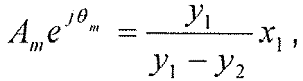
- The following equation may be used to calculate the parameters Am and θm of the anti-ripple signal to be injected with respect to the mth signal harmonic:

m , y2 = Cmejψm ,
- According to an embodiment of the present invention, the steps 1-4 above are performed simultaneously for the signal harmonics of the respective orders in the pressure rippled signal, i.e. simultaneously determining the corresponding parameters Am and θm of the signal harmonics of the respective orders, and the time required is the same as that for determining a signal harmonic of a single order of, and mainly depends on the spectrum analysis, such as FFT or digital PLL.
- For high gain control, Gm is small and thus may be sensitive. In this case, the following formula is substituted for the above formula to determine x1,

- The anti-ripple injection method according to embodiments of the present invention is described above. The anti-ripple injection method can be implemented by
anti-ripple injection apparatuses - Now referring to
Fig. 7 , it illustrates an exemplary structure diagram of theanti-ripple injection apparatus 
- According to an embodiment of the present invention, the parameters of the anti-ripple signal are automatically set according to the output signal of a system sensor without any manual adjustment.
- According to an embodiment of the present invention, the system sensor comprises any one or more of the following: a pressure sensor, an angle sensor, a speed sensor, a current sensor, and a voltage sensor.
- According to an embodiment of the present invention, the
anti-ripple injection apparatuses parameter determination module 720 configured to determine the Am and θm by extracting the corresponding parameters of the mth signal harmonic from a pressure ripple signal. - According to an embodiment of the present invention, the
parameter determination module 720 comprises aspectrum analysis sub-module 721 and aparameter calculation sub-module 722, wherein
thespectrum analysis sub-module 721 is configured to perform spectrum analysis on the mth signal harmonic in the pressure ripple signal to obtain the magnitude Bm and phase φ m. thereof;
theinjection module 722 is further configured to inject into the control system an anti-ripple signal represented by Bm/Gm cos(mθ + φ m) based on (Bm,φ m) and a gain Gm from the corresponding node to the pressure node in the control system;
thespectrum analysis sub-module 710 is further configured to calculate the mth signal harmonic in the pressure ripple signals using spectrum analysis to obtain an updated magnitude Cm and phase ψ m thereof;
theparameter calculation sub-module 722 is configured to calculate with the following equation parameters Am and θm of the anti-ripple signal to be injected with respect to the mth signal harmonic:
m , y2 = Cmejψm ,
- According to some other embodiments of the present invention, the parameter calculation sub-module 723 is configured to calculate with the following equation parameters Am and θm of the anti-ripple signal to be injected with respect to the mth signal harmonic:

m , y2 = Cmejψm ,
- According to an embodiment of the present invention, the
parameter determination module 720 is further configured to simultaneously perform the determination of the Am and θm by extracting corresponding parameters of the mth signal harmonic from a pressure ripple signal, with respect to a set of different mth signal harmonics in the pressure ripple signal. - According to an embodiment of the present invention, the
spectrum analysis sub-module 721 performs spectrum analysis by the Fast Fourier Transform. - According to an embodiment of the present invention, the
spectrum analysis sub-module 721 performs spectrum analysis by the digital Phase-Locked Loop (PLL). - According to an embodiment of the present invention, the digital PLL is based on the following formulas:


- According to an embodiment of the present invention, the
injection module 710 is further configured to inject the anti-ripple signal into a speed loop of the control system. - According to an embodiment of the present invention, the
injection module 710 is further configured to inject the anti-ripple signal into a current loop of the control system. - As described above, in another aspect, the present invention provides a control system of a VFD-based hydraulic pump, comprising: the anti-ripple injection apparatus according to an embodiment of the present invention.
- In yet another aspect, the present invention further provides a pump system, comprising: an electric motor drive, an electric motor, and a pump, wherein the electric motor drive comprises the control system above.
- An anti-ripple injection apparatus, a control system of a VFD-based hydraulic pump and a hydraulic pump system according to embodiments of the present invention are described above. It should be pointed out that the description above is only exemplary, not limitation to the present invention. In other embodiments of the present invention, the apparatus and system may have more, less or different modules, and the including, connecting and functional relations among these modules may be different from that described herein. For example, usually a function performed by one module may also be performed by another module, and different modules may be combined or split arbitrarily, and so on.
- Exemplary embodiments of the present invention are described above, but the present invention is not limited to this. Those skilled in the art may make various changes and modifications without diverging from the scope of the present invention. For example, it is contemplated that the technical solution of the present invention is also applicable to other fluid pumps apart from the hydraulic pump. The scope of the present invention is only defined by the claims.
Claims (12)
- An anti-ripple injection method for injecting an anti-ripple signal into a control system of a pump (330), the control system controlling an electric motor (320) via an electric motor drive (310), the electric motor (320) driving the pump (330), the anti-ripple signal causing pressure ripples in the pump output to be at least partially cancelled,
characterized in that the anti-ripple injection method comprises:
injecting an anti-ripple signal into the control system, the anti-ripple signal being represented by the following equation: wherein θ is the rotation angle of the motor shaft, m is the order of a signal harmonic in the anti-ripple signal, Am and θm are parameters with respect to the mth signal harmonic; anddetermining the Am and θm by extracting the corresponding parameters of the mth signal harmonic from a pressure ripple signal.
 - The anti-ripple injection method according to claim 1, wherein the parameters of the anti-ripple signal are automatically set according to the output signal of a system sensor without any manual adjustment.
- The anti-ripple injection method according to claim 2, wherein the system sensor includes any one or more of the following: a pressure sensor, an angle sensor, a speed sensor, a current sensor, and a voltage sensor.
- The anti-ripple injection method according to any of the preceding claims, wherein determining the Am and θm by extracting the corresponding parameters of the mth signal harmonic from a pressure ripple signal comprises:performing spectrum analysis on the mth signal harmonic in the pressure ripple signal to obtain the magnitude Bm and phase φm thereof;injecting into the control system an anti-ripple signal represented by Bm /Gm cos(mθ + φm ) based on (Bm ,φm ) and a gain Gm from the corresponding node to the pressure node in the control system;calculating the mth signal harmonic in the pressure ripple signal using spectrum analysis to obtain an updated magnitude Cm and phase ψm thereof;calculating with the following equation parameters Am and θm of the anti-ripple signal to be injected with respect to the mth signal harmonic:
m , y 2 = Cmejψm ,
- The anti-ripple injection method according to any of claims 1 to 3, wherein the determining the Am and θm by extracting the corresponding parameters of the mth signal harmonic from a pressure ripple signal comprises:performing spectrum analysis on the mth signal harmonic in the pressure ripple signal to obtain the magnitude Bm and phase φm thereof;injecting into the control system an anti-ripple signal represented by Bm /Gm cos(mθ + φm ) based on (Bm ,φm ) and a gain Gm from the corresponding node to the pressure node in the control system;calculating the mth signal harmonic in the pressure ripple signal using spectrum analysis to obtain an updated magnitude Cm and phase ψm thereof;calculating with the following equation parameters Am and θm of the anti-ripple signal to be injected with respect to the mth signal harmonic:

m , y 2 = Cmejψm ,
- The anti-ripple injection method according to claim 4 or 5, wherein the determining the Am and θm by extracting the corresponding parameters of the mth signal harmonic from a pressure ripple signal are performed simultaneously with respect to a set of different mth signal harmonics in the pressure ripple signal.
- The anti-ripple injection method according to claim 4 or 5, wherein the spectrum analysis is realized by the Fast Fourier Transform.
- The anti-ripple injection method according to claim 4 or 5, wherein the spectrum analysis is realized by the digital Phase-Locked Loop (PLL).
- The anti-ripple injection method according to claim 8, wherein the digital PLL is based on the following formulas:


- The anti-ripple injection method according to any of the preceding claims, wherein the anti-ripple signal is injected into a speed loop of the control system.
- The anti-ripple injection method according to any of claims 1 to 9, wherein the anti-ripple signal is injected into a current loop of the control system.
- A pump system (300), comprising:a VFD,a pump (330),an electric motor (320) for driving the pump (330), wherein the VFD comprises a control system for controlling the electric motor (320) via an electric motor drive (310);wherein the VFD further comprises an anti-ripple injection apparatus for injecting an anti-ripple signal into the control system, the anti-ripple signal causing pressure ripples in the pump output to be at least partially cancelled, the anti-ripple injection apparatus configured to perform the anti-ripple injection method according to any of claims 1 to 11.
Applications Claiming Priority (2)
| Application Number | Priority Date | Filing Date | Title |
|---|---|---|---|
| CN201310268767.8A CN104251202B (en) | 2013-06-28 | 2013-06-28 | Offset the control system of fluctuation method for implanting and device and pump |
| PCT/CN2014/080975 WO2014206340A1 (en) | 2013-06-28 | 2014-06-27 | Anti-ripple injection method and apparatus and control system of a pump |
Publications (3)
| Publication Number | Publication Date |
|---|---|
| EP3014122A1 EP3014122A1 (en) | 2016-05-04 |
| EP3014122A4 EP3014122A4 (en) | 2017-03-15 |
| EP3014122B1 true EP3014122B1 (en) | 2019-04-17 |
Family
ID=52141103
Family Applications (1)
| Application Number | Title | Priority Date | Filing Date |
|---|---|---|---|
| EP14817204.2A Active EP3014122B1 (en) | 2013-06-28 | 2014-06-27 | Anti-ripple injection method and pump system |
Country Status (4)
| Country | Link |
|---|---|
| US (1) | US10527035B2 (en) |
| EP (1) | EP3014122B1 (en) |
| CN (1) | CN104251202B (en) |
| WO (1) | WO2014206340A1 (en) |
Families Citing this family (8)
| Publication number | Priority date | Publication date | Assignee | Title |
|---|---|---|---|---|
| DE102015201961A1 (en) * | 2015-02-04 | 2016-08-04 | Volkswagen Aktiengesellschaft | Method for operating a positive displacement pump and a dedicated positive displacement pump |
| DE102016106483B4 (en) * | 2016-04-08 | 2019-02-07 | Jenaer Antriebstechnik Gmbh | Method for compensation of cyclical disturbances during operation of a pump and control unit |
| CN106836379B (en) * | 2017-02-16 | 2019-11-05 | 江苏大学 | It is a kind of can intelligent vibration damping pumping plant installation method |
| JP6594381B2 (en) * | 2017-08-10 | 2019-10-23 | 本田技研工業株式会社 | Hydraulic control device |
| EP3735278A1 (en) * | 2018-01-02 | 2020-11-11 | KCI Licensing, Inc. | Negative pressure wound therapy device with silent piezoelectric pump |
| US12060877B2 (en) * | 2020-09-18 | 2024-08-13 | Caterpillar Inc. | Hydraulic fracturing pump control system |
| CN112506122A (en) * | 2020-09-21 | 2021-03-16 | 中船第九设计研究院工程有限公司 | Wave-absorbing shore electric control method |
| DE102021211175A1 (en) * | 2021-10-04 | 2023-04-06 | Vitesco Technologies GmbH | Method for operating an electric motor, feed pump, motor vehicle with such a feed pump, computer program and computer-readable medium |
Family Cites Families (18)
| Publication number | Priority date | Publication date | Assignee | Title |
|---|---|---|---|---|
| DE3139925A1 (en) * | 1981-10-08 | 1983-07-14 | Hewlett-Packard GmbH, 7030 Böblingen | HIGH PRESSURE DOSING PUMP |
| US4822250A (en) * | 1986-03-24 | 1989-04-18 | Hitachi, Ltd. | Apparatus for transferring small amount of fluid |
| US5108264A (en) * | 1990-08-20 | 1992-04-28 | Hewlett-Packard Company | Method and apparatus for real time compensation of fluid compressibility in high pressure reciprocating pumps |
| JPH07286584A (en) * | 1994-04-19 | 1995-10-31 | Hitachi Ltd | Inverter driven screw compressor |
| US5668457A (en) * | 1995-06-30 | 1997-09-16 | Martin Marietta Corporation | Variable-frequency AC induction motor controller |
| US5971714A (en) * | 1996-05-29 | 1999-10-26 | Graco Inc | Electronic CAM compensation of pressure change of servo controlled pumps |
| JPH10159743A (en) * | 1996-11-29 | 1998-06-16 | Tokimec Inc | Hydraulic control system |
| JP3995227B2 (en) * | 1999-01-21 | 2007-10-24 | 株式会社スギノマシン | Liquid pressurizer |
| US6684635B2 (en) * | 2001-12-27 | 2004-02-03 | Caterpillar Inc | System and method for controlling motor torque |
| DE10334817A1 (en) * | 2003-07-30 | 2005-03-10 | Bosch Rexroth Ag | Pump failure detection unit uses Fourier analysis of pressure sensor measurement to determine if characteristic frequency exceeds reference amplitude |
| KR100690663B1 (en) * | 2005-05-06 | 2007-03-09 | 엘지전자 주식회사 | Operation control device and method of variable displacement reciprocating compressor |
| DE102005025590A1 (en) * | 2005-06-03 | 2006-12-07 | Hydac Electronic Gmbh | Regulating device and method for operating a control device |
| US8425202B2 (en) * | 2005-07-21 | 2013-04-23 | Xylem Ip Holdings Llc | Modular, universal and automatic closed-loop pump pressure controller |
| CN201057139Y (en) * | 2007-06-22 | 2008-05-07 | 谭书涛 | Pressure controller of fluid pump |
| JP5337662B2 (en) * | 2009-10-14 | 2013-11-06 | 川崎重工業株式会社 | Apparatus and method for operating hydraulic pump in hydraulic system |
| ATE552423T1 (en) * | 2010-02-12 | 2012-04-15 | Allweiler Ag | OPERATIONAL CONTROL DEVICE FOR A DISPLACEMENT PUMP, PUMP SYSTEM AND METHOD FOR OPERATING SAME |
| AU2011226625B2 (en) * | 2010-03-12 | 2014-11-27 | Franklin Electric Company, Inc. | Variable speed drive system |
| WO2013114436A1 (en) * | 2012-01-31 | 2013-08-08 | Mitsubishi Heavy Industries, Ltd. | Method of controlling a hydraulic machine to reduce torque ripple and/or bearing side load |
-
2013
- 2013-06-28 CN CN201310268767.8A patent/CN104251202B/en active Active
-
2014
- 2014-06-27 WO PCT/CN2014/080975 patent/WO2014206340A1/en not_active Ceased
- 2014-06-27 EP EP14817204.2A patent/EP3014122B1/en active Active
- 2014-06-27 US US14/900,010 patent/US10527035B2/en active Active
Non-Patent Citations (1)
| Title |
|---|
| None * |
Also Published As
| Publication number | Publication date |
|---|---|
| EP3014122A4 (en) | 2017-03-15 |
| US10527035B2 (en) | 2020-01-07 |
| CN104251202B (en) | 2017-03-01 |
| CN104251202A (en) | 2014-12-31 |
| US20170298924A1 (en) | 2017-10-19 |
| EP3014122A1 (en) | 2016-05-04 |
| WO2014206340A1 (en) | 2014-12-31 |
Similar Documents
| Publication | Publication Date | Title |
|---|---|---|
| US10527035B2 (en) | Anti-ripple injection method and apparatus and control system of a pump | |
| US10655621B2 (en) | Control system and method of a VFD-based pump and pump system | |
| EP3098449B1 (en) | Method and device for automatically compensating for moment of compressor, compressor, and control method for same | |
| US8890454B2 (en) | Phase locked loop based torsional mode damping system and method | |
| US9531313B2 (en) | Apparatus for controlling controlled variable of rotary machine to command value | |
| EP3297156B1 (en) | Torque ripple reduction for a generator | |
| EP2552013A1 (en) | Reduction of noise and vibrations of an electromechanical transducer by using a modified stator coil drive signal comprising harmonic components | |
| US9350284B2 (en) | Power conversion device | |
| AU2011234461B9 (en) | Rectifier based torsional mode damping system and method | |
| US20130106330A1 (en) | Rectifier and inverter based torsional mode damping system and method | |
| CN103746619A (en) | Synchronous motor start control method and system | |
| JP2019083672A (en) | Inverter, and drive control method for motor | |
| JP2009303435A (en) | Motor controller | |
| TR201702422A2 (en) | Method of controlling a permanent magnet motor. | |
| Niedermayr et al. | Sensorless control of a super-high speed synchronous motor drive based on a Kalman filter | |
| Abedinzadeh et al. | A comprehensive sensorless control of DFIG-based wind turbines | |
| Li et al. | Research on main circuit and control strategy of the oil fracturing frequency converter | |
| Rossi et al. | Discrete multi-layer estimator implementation for sensorless control of elastic drive systems—An industrial case study | |
| CN121396012A (en) | Double closed-loop vector control method of permanent magnet synchronous motor and DSP processor | |
| Houari et al. | Speed Ripples Reduction of PMSM Drives under Low-Speed Working Conditions | |
| Junshan et al. | Low-speed performance improvement of direct torque control and simulation validation |
Legal Events
| Date | Code | Title | Description |
|---|---|---|---|
| PUAI | Public reference made under article 153(3) epc to a published international application that has entered the european phase |
Free format text: ORIGINAL CODE: 0009012 |
|
| 17P | Request for examination filed |
Effective date: 20151214 |
|
| AK | Designated contracting states |
Kind code of ref document: A1 Designated state(s): AL AT BE BG CH CY CZ DE DK EE ES FI FR GB GR HR HU IE IS IT LI LT LU LV MC MK MT NL NO PL PT RO RS SE SI SK SM TR |
|
| AX | Request for extension of the european patent |
Extension state: BA ME |
|
| RIN1 | Information on inventor provided before grant (corrected) |
Inventor name: CHENG, XIAOMENG Inventor name: CHEN, YILUN |
|
| DAX | Request for extension of the european patent (deleted) | ||
| REG | Reference to a national code |
Ref country code: DE Ref legal event code: R079 Ref document number: 602014045019 Country of ref document: DE Free format text: PREVIOUS MAIN CLASS: F04B0049060000 Ipc: F04B0011000000 |
|
| A4 | Supplementary search report drawn up and despatched |
Effective date: 20170213 |
|
| RIC1 | Information provided on ipc code assigned before grant |
Ipc: F04B 11/00 20060101AFI20170207BHEP Ipc: F04B 49/08 20060101ALI20170207BHEP Ipc: F04B 49/06 20060101ALI20170207BHEP Ipc: F04B 17/03 20060101ALI20170207BHEP |
|
| STAA | Information on the status of an ep patent application or granted ep patent |
Free format text: STATUS: EXAMINATION IS IN PROGRESS |
|
| 17Q | First examination report despatched |
Effective date: 20171220 |
|
| GRAP | Despatch of communication of intention to grant a patent |
Free format text: ORIGINAL CODE: EPIDOSNIGR1 |
|
| STAA | Information on the status of an ep patent application or granted ep patent |
Free format text: STATUS: GRANT OF PATENT IS INTENDED |
|
| INTG | Intention to grant announced |
Effective date: 20181212 |
|
| GRAS | Grant fee paid |
Free format text: ORIGINAL CODE: EPIDOSNIGR3 |
|
| GRAA | (expected) grant |
Free format text: ORIGINAL CODE: 0009210 |
|
| STAA | Information on the status of an ep patent application or granted ep patent |
Free format text: STATUS: THE PATENT HAS BEEN GRANTED |
|
| AK | Designated contracting states |
Kind code of ref document: B1 Designated state(s): AL AT BE BG CH CY CZ DE DK EE ES FI FR GB GR HR HU IE IS IT LI LT LU LV MC MK MT NL NO PL PT RO RS SE SI SK SM TR |
|
| REG | Reference to a national code |
Ref country code: GB Ref legal event code: FG4D |
|
| REG | Reference to a national code |
Ref country code: CH Ref legal event code: EP |
|
| REG | Reference to a national code |
Ref country code: DE Ref legal event code: R096 Ref document number: 602014045019 Country of ref document: DE |
|
| REG | Reference to a national code |
Ref country code: AT Ref legal event code: REF Ref document number: 1121840 Country of ref document: AT Kind code of ref document: T Effective date: 20190515 Ref country code: IE Ref legal event code: FG4D |
|
| REG | Reference to a national code |
Ref country code: NL Ref legal event code: MP Effective date: 20190417 |
|
| REG | Reference to a national code |
Ref country code: LT Ref legal event code: MG4D |
|
| PG25 | Lapsed in a contracting state [announced via postgrant information from national office to epo] |
Ref country code: NL Free format text: LAPSE BECAUSE OF FAILURE TO SUBMIT A TRANSLATION OF THE DESCRIPTION OR TO PAY THE FEE WITHIN THE PRESCRIBED TIME-LIMIT Effective date: 20190417 |
|
| PG25 | Lapsed in a contracting state [announced via postgrant information from national office to epo] |
Ref country code: FI Free format text: LAPSE BECAUSE OF FAILURE TO SUBMIT A TRANSLATION OF THE DESCRIPTION OR TO PAY THE FEE WITHIN THE PRESCRIBED TIME-LIMIT Effective date: 20190417 Ref country code: AL Free format text: LAPSE BECAUSE OF FAILURE TO SUBMIT A TRANSLATION OF THE DESCRIPTION OR TO PAY THE FEE WITHIN THE PRESCRIBED TIME-LIMIT Effective date: 20190417 Ref country code: NO Free format text: LAPSE BECAUSE OF FAILURE TO SUBMIT A TRANSLATION OF THE DESCRIPTION OR TO PAY THE FEE WITHIN THE PRESCRIBED TIME-LIMIT Effective date: 20190717 Ref country code: PT Free format text: LAPSE BECAUSE OF FAILURE TO SUBMIT A TRANSLATION OF THE DESCRIPTION OR TO PAY THE FEE WITHIN THE PRESCRIBED TIME-LIMIT Effective date: 20190817 Ref country code: ES Free format text: LAPSE BECAUSE OF FAILURE TO SUBMIT A TRANSLATION OF THE DESCRIPTION OR TO PAY THE FEE WITHIN THE PRESCRIBED TIME-LIMIT Effective date: 20190417 Ref country code: HR Free format text: LAPSE BECAUSE OF FAILURE TO SUBMIT A TRANSLATION OF THE DESCRIPTION OR TO PAY THE FEE WITHIN THE PRESCRIBED TIME-LIMIT Effective date: 20190417 Ref country code: SE Free format text: LAPSE BECAUSE OF FAILURE TO SUBMIT A TRANSLATION OF THE DESCRIPTION OR TO PAY THE FEE WITHIN THE PRESCRIBED TIME-LIMIT Effective date: 20190417 Ref country code: LT Free format text: LAPSE BECAUSE OF FAILURE TO SUBMIT A TRANSLATION OF THE DESCRIPTION OR TO PAY THE FEE WITHIN THE PRESCRIBED TIME-LIMIT Effective date: 20190417 |
|
| PG25 | Lapsed in a contracting state [announced via postgrant information from national office to epo] |
Ref country code: RS Free format text: LAPSE BECAUSE OF FAILURE TO SUBMIT A TRANSLATION OF THE DESCRIPTION OR TO PAY THE FEE WITHIN THE PRESCRIBED TIME-LIMIT Effective date: 20190417 Ref country code: LV Free format text: LAPSE BECAUSE OF FAILURE TO SUBMIT A TRANSLATION OF THE DESCRIPTION OR TO PAY THE FEE WITHIN THE PRESCRIBED TIME-LIMIT Effective date: 20190417 Ref country code: GR Free format text: LAPSE BECAUSE OF FAILURE TO SUBMIT A TRANSLATION OF THE DESCRIPTION OR TO PAY THE FEE WITHIN THE PRESCRIBED TIME-LIMIT Effective date: 20190718 Ref country code: BG Free format text: LAPSE BECAUSE OF FAILURE TO SUBMIT A TRANSLATION OF THE DESCRIPTION OR TO PAY THE FEE WITHIN THE PRESCRIBED TIME-LIMIT Effective date: 20190717 Ref country code: PL Free format text: LAPSE BECAUSE OF FAILURE TO SUBMIT A TRANSLATION OF THE DESCRIPTION OR TO PAY THE FEE WITHIN THE PRESCRIBED TIME-LIMIT Effective date: 20190417 |
|
| REG | Reference to a national code |
Ref country code: AT Ref legal event code: MK05 Ref document number: 1121840 Country of ref document: AT Kind code of ref document: T Effective date: 20190417 |
|
| PG25 | Lapsed in a contracting state [announced via postgrant information from national office to epo] |
Ref country code: IS Free format text: LAPSE BECAUSE OF FAILURE TO SUBMIT A TRANSLATION OF THE DESCRIPTION OR TO PAY THE FEE WITHIN THE PRESCRIBED TIME-LIMIT Effective date: 20190817 |
|
| REG | Reference to a national code |
Ref country code: DE Ref legal event code: R097 Ref document number: 602014045019 Country of ref document: DE |
|
| PG25 | Lapsed in a contracting state [announced via postgrant information from national office to epo] |
Ref country code: CZ Free format text: LAPSE BECAUSE OF FAILURE TO SUBMIT A TRANSLATION OF THE DESCRIPTION OR TO PAY THE FEE WITHIN THE PRESCRIBED TIME-LIMIT Effective date: 20190417 Ref country code: MC Free format text: LAPSE BECAUSE OF FAILURE TO SUBMIT A TRANSLATION OF THE DESCRIPTION OR TO PAY THE FEE WITHIN THE PRESCRIBED TIME-LIMIT Effective date: 20190417 Ref country code: SK Free format text: LAPSE BECAUSE OF FAILURE TO SUBMIT A TRANSLATION OF THE DESCRIPTION OR TO PAY THE FEE WITHIN THE PRESCRIBED TIME-LIMIT Effective date: 20190417 Ref country code: AT Free format text: LAPSE BECAUSE OF FAILURE TO SUBMIT A TRANSLATION OF THE DESCRIPTION OR TO PAY THE FEE WITHIN THE PRESCRIBED TIME-LIMIT Effective date: 20190417 Ref country code: EE Free format text: LAPSE BECAUSE OF FAILURE TO SUBMIT A TRANSLATION OF THE DESCRIPTION OR TO PAY THE FEE WITHIN THE PRESCRIBED TIME-LIMIT Effective date: 20190417 Ref country code: DK Free format text: LAPSE BECAUSE OF FAILURE TO SUBMIT A TRANSLATION OF THE DESCRIPTION OR TO PAY THE FEE WITHIN THE PRESCRIBED TIME-LIMIT Effective date: 20190417 Ref country code: RO Free format text: LAPSE BECAUSE OF FAILURE TO SUBMIT A TRANSLATION OF THE DESCRIPTION OR TO PAY THE FEE WITHIN THE PRESCRIBED TIME-LIMIT Effective date: 20190417 |
|
| REG | Reference to a national code |
Ref country code: CH Ref legal event code: PL |
|
| PLBE | No opposition filed within time limit |
Free format text: ORIGINAL CODE: 0009261 |
|
| STAA | Information on the status of an ep patent application or granted ep patent |
Free format text: STATUS: NO OPPOSITION FILED WITHIN TIME LIMIT |
|
| PG25 | Lapsed in a contracting state [announced via postgrant information from national office to epo] |
Ref country code: SM Free format text: LAPSE BECAUSE OF FAILURE TO SUBMIT A TRANSLATION OF THE DESCRIPTION OR TO PAY THE FEE WITHIN THE PRESCRIBED TIME-LIMIT Effective date: 20190417 |
|
| 26N | No opposition filed |
Effective date: 20200120 |
|
| REG | Reference to a national code |
Ref country code: BE Ref legal event code: MM Effective date: 20190630 |
|
| PG25 | Lapsed in a contracting state [announced via postgrant information from national office to epo] |
Ref country code: TR Free format text: LAPSE BECAUSE OF FAILURE TO SUBMIT A TRANSLATION OF THE DESCRIPTION OR TO PAY THE FEE WITHIN THE PRESCRIBED TIME-LIMIT Effective date: 20190417 |
|
| PG25 | Lapsed in a contracting state [announced via postgrant information from national office to epo] |
Ref country code: IE Free format text: LAPSE BECAUSE OF NON-PAYMENT OF DUE FEES Effective date: 20190627 |
|
| PG25 | Lapsed in a contracting state [announced via postgrant information from national office to epo] |
Ref country code: SI Free format text: LAPSE BECAUSE OF FAILURE TO SUBMIT A TRANSLATION OF THE DESCRIPTION OR TO PAY THE FEE WITHIN THE PRESCRIBED TIME-LIMIT Effective date: 20190417 Ref country code: BE Free format text: LAPSE BECAUSE OF NON-PAYMENT OF DUE FEES Effective date: 20190630 Ref country code: CH Free format text: LAPSE BECAUSE OF NON-PAYMENT OF DUE FEES Effective date: 20190630 Ref country code: LU Free format text: LAPSE BECAUSE OF NON-PAYMENT OF DUE FEES Effective date: 20190627 Ref country code: LI Free format text: LAPSE BECAUSE OF NON-PAYMENT OF DUE FEES Effective date: 20190630 |
|
| PG25 | Lapsed in a contracting state [announced via postgrant information from national office to epo] |
Ref country code: FR Free format text: LAPSE BECAUSE OF NON-PAYMENT OF DUE FEES Effective date: 20190630 |
|
| PG25 | Lapsed in a contracting state [announced via postgrant information from national office to epo] |
Ref country code: CY Free format text: LAPSE BECAUSE OF FAILURE TO SUBMIT A TRANSLATION OF THE DESCRIPTION OR TO PAY THE FEE WITHIN THE PRESCRIBED TIME-LIMIT Effective date: 20190417 |
|
| PG25 | Lapsed in a contracting state [announced via postgrant information from national office to epo] |
Ref country code: MT Free format text: LAPSE BECAUSE OF FAILURE TO SUBMIT A TRANSLATION OF THE DESCRIPTION OR TO PAY THE FEE WITHIN THE PRESCRIBED TIME-LIMIT Effective date: 20190417 Ref country code: HU Free format text: LAPSE BECAUSE OF FAILURE TO SUBMIT A TRANSLATION OF THE DESCRIPTION OR TO PAY THE FEE WITHIN THE PRESCRIBED TIME-LIMIT; INVALID AB INITIO Effective date: 20140627 |
|
| REG | Reference to a national code |
Ref country code: DE Ref legal event code: R081 Ref document number: 602014045019 Country of ref document: DE Owner name: DANFOSS POWER SOLUTIONS II TECHNOLOGY A/S, DK Free format text: FORMER OWNER: EATON CORPORATION, CLEVELAND, OHIO, US Ref country code: DE Ref legal event code: R081 Ref document number: 602014045019 Country of ref document: DE Owner name: DANFOSS A/S, DK Free format text: FORMER OWNER: EATON CORPORATION, CLEVELAND, OHIO, US |
|
| REG | Reference to a national code |
Ref country code: GB Ref legal event code: 732E Free format text: REGISTERED BETWEEN 20220606 AND 20220608 |
|
| PG25 | Lapsed in a contracting state [announced via postgrant information from national office to epo] |
Ref country code: MK Free format text: LAPSE BECAUSE OF FAILURE TO SUBMIT A TRANSLATION OF THE DESCRIPTION OR TO PAY THE FEE WITHIN THE PRESCRIBED TIME-LIMIT Effective date: 20190417 |
|
| P01 | Opt-out of the competence of the unified patent court (upc) registered |
Effective date: 20230617 |
|
| REG | Reference to a national code |
Ref country code: GB Ref legal event code: 732E Free format text: REGISTERED BETWEEN 20231005 AND 20231011 |
|
| REG | Reference to a national code |
Ref country code: DE Ref legal event code: R081 Ref document number: 602014045019 Country of ref document: DE Owner name: DANFOSS A/S, DK Free format text: FORMER OWNER: DANFOSS POWER SOLUTIONS II TECHNOLOGY A/S, NORDBORG, DK |
|
| PGFP | Annual fee paid to national office [announced via postgrant information from national office to epo] |
Ref country code: DE Payment date: 20250507 Year of fee payment: 12 |
|
| PGFP | Annual fee paid to national office [announced via postgrant information from national office to epo] |
Ref country code: GB Payment date: 20250508 Year of fee payment: 12 |
|
| PGFP | Annual fee paid to national office [announced via postgrant information from national office to epo] |
Ref country code: IT Payment date: 20250522 Year of fee payment: 12 |