EP3013757B1 - Abwasserbehandlungssystem umfassend einen äusseren tank und eine innere belüftungskammer - Google Patents
Abwasserbehandlungssystem umfassend einen äusseren tank und eine innere belüftungskammer Download PDFInfo
- Publication number
- EP3013757B1 EP3013757B1 EP14728608.2A EP14728608A EP3013757B1 EP 3013757 B1 EP3013757 B1 EP 3013757B1 EP 14728608 A EP14728608 A EP 14728608A EP 3013757 B1 EP3013757 B1 EP 3013757B1
- Authority
- EP
- European Patent Office
- Prior art keywords
- treatment system
- wastewater treatment
- outer tank
- aeration chamber
- open
- Prior art date
- Legal status (The legal status is an assumption and is not a legal conclusion. Google has not performed a legal analysis and makes no representation as to the accuracy of the status listed.)
- Active
Links
Images


Classifications
-
- C—CHEMISTRY; METALLURGY
- C02—TREATMENT OF WATER, WASTE WATER, SEWAGE, OR SLUDGE
- C02F—TREATMENT OF WATER, WASTE WATER, SEWAGE, OR SLUDGE
- C02F3/00—Biological treatment of water, waste water, or sewage
- C02F3/02—Aerobic processes
- C02F3/12—Activated sludge processes
- C02F3/1236—Particular type of activated sludge installations
- C02F3/1242—Small compact installations for use in homes, apartment blocks, hotels or the like
- C02F3/1247—Small compact installations for use in homes, apartment blocks, hotels or the like comprising circular tanks with elements, e.g. decanters, aeration basins, in the form of segments, crowns or sectors
-
- C—CHEMISTRY; METALLURGY
- C02—TREATMENT OF WATER, WASTE WATER, SEWAGE, OR SLUDGE
- C02F—TREATMENT OF WATER, WASTE WATER, SEWAGE, OR SLUDGE
- C02F3/00—Biological treatment of water, waste water, or sewage
- C02F3/02—Aerobic processes
- C02F3/12—Activated sludge processes
- C02F3/1236—Particular type of activated sludge installations
- C02F3/1242—Small compact installations for use in homes, apartment blocks, hotels or the like
-
- C—CHEMISTRY; METALLURGY
- C02—TREATMENT OF WATER, WASTE WATER, SEWAGE, OR SLUDGE
- C02F—TREATMENT OF WATER, WASTE WATER, SEWAGE, OR SLUDGE
- C02F3/00—Biological treatment of water, waste water, or sewage
- C02F3/02—Aerobic processes
- C02F3/12—Activated sludge processes
- C02F3/1278—Provisions for mixing or aeration of the mixed liquor
-
- C—CHEMISTRY; METALLURGY
- C02—TREATMENT OF WATER, WASTE WATER, SEWAGE, OR SLUDGE
- C02F—TREATMENT OF WATER, WASTE WATER, SEWAGE, OR SLUDGE
- C02F3/00—Biological treatment of water, waste water, or sewage
- C02F3/02—Aerobic processes
- C02F3/12—Activated sludge processes
- C02F3/20—Activated sludge processes using diffusers
-
- C—CHEMISTRY; METALLURGY
- C02—TREATMENT OF WATER, WASTE WATER, SEWAGE, OR SLUDGE
- C02F—TREATMENT OF WATER, WASTE WATER, SEWAGE, OR SLUDGE
- C02F3/00—Biological treatment of water, waste water, or sewage
- C02F3/02—Aerobic processes
- C02F3/12—Activated sludge processes
- C02F3/22—Activated sludge processes using circulation pipes
-
- C—CHEMISTRY; METALLURGY
- C02—TREATMENT OF WATER, WASTE WATER, SEWAGE, OR SLUDGE
- C02F—TREATMENT OF WATER, WASTE WATER, SEWAGE, OR SLUDGE
- C02F2201/00—Apparatus for treatment of water, waste water or sewage
- C02F2201/002—Construction details of the apparatus
- C02F2201/003—Coaxial constructions, e.g. a cartridge located coaxially within another
-
- C—CHEMISTRY; METALLURGY
- C02—TREATMENT OF WATER, WASTE WATER, SEWAGE, OR SLUDGE
- C02F—TREATMENT OF WATER, WASTE WATER, SEWAGE, OR SLUDGE
- C02F2203/00—Apparatus and plants for the biological treatment of water, waste water or sewage
- C02F2203/006—Apparatus and plants for the biological treatment of water, waste water or sewage details of construction, e.g. specially adapted seals, modules, connections
-
- Y—GENERAL TAGGING OF NEW TECHNOLOGICAL DEVELOPMENTS; GENERAL TAGGING OF CROSS-SECTIONAL TECHNOLOGIES SPANNING OVER SEVERAL SECTIONS OF THE IPC; TECHNICAL SUBJECTS COVERED BY FORMER USPC CROSS-REFERENCE ART COLLECTIONS [XRACs] AND DIGESTS
- Y02—TECHNOLOGIES OR APPLICATIONS FOR MITIGATION OR ADAPTATION AGAINST CLIMATE CHANGE
- Y02A—TECHNOLOGIES FOR ADAPTATION TO CLIMATE CHANGE
- Y02A20/00—Water conservation; Efficient water supply; Efficient water use
- Y02A20/20—Controlling water pollution; Waste water treatment
- Y02A20/208—Off-grid powered water treatment
-
- Y—GENERAL TAGGING OF NEW TECHNOLOGICAL DEVELOPMENTS; GENERAL TAGGING OF CROSS-SECTIONAL TECHNOLOGIES SPANNING OVER SEVERAL SECTIONS OF THE IPC; TECHNICAL SUBJECTS COVERED BY FORMER USPC CROSS-REFERENCE ART COLLECTIONS [XRACs] AND DIGESTS
- Y02—TECHNOLOGIES OR APPLICATIONS FOR MITIGATION OR ADAPTATION AGAINST CLIMATE CHANGE
- Y02W—CLIMATE CHANGE MITIGATION TECHNOLOGIES RELATED TO WASTEWATER TREATMENT OR WASTE MANAGEMENT
- Y02W10/00—Technologies for wastewater treatment
- Y02W10/10—Biological treatment of water, waste water, or sewage
Definitions
- the present invention relates to a wastewater treatment system and particularly to aerobic waste treatment systems suitable for use as a domestic sewage treatment system.
- wastewater a combination of waste and water
- More recently aerobic waste treatment systems have been developed in which the waste is broken down into carbon dioxide and water.
- the containment tanks are designed to accommodate waste for up to 12 months or more without the need for skimming or de-sludging. So even for the domestic market, the capacities of domestic containment tanks tend to be from 2,000 litres up to, for example, 20,000 litres.
- US 5441634 a tank that is suitable for either anaerobic or aerobic treatment of wastewater is described which provides for circulation of the wastewater within the tank.
- the tank contains an inverted funnel structure in combination with an effluent weir.
- the inverted funnel structure constricts upward flow of a gas borne mixture within the fluid enabling the mixture to be degassed so that any gas borne solids settle out of the mixture.
- the weir is used to keep the clear effluent isolated from the wastewater.
- US 54416340 is silent on the method of construction of the wastewater system and in particular how the funnel structure and the weir are mounted within the tank.
- WO 2010/132877 an alternative aerobic wastewater treatment system is described.
- the system generally comprises an outer tank containing an aeration chamber, a submerged aerator within a vertically extending tube and an effluent weir supporting a circumferentially extending scum baffle.
- the outer tank is preferably formed as a one-piece component using fiberglass reinforced plastic and includes an outwardly directed circumferential ledge intermediate the top and bottom of the tank.
- a preferred embodiment of the system described in WO 2010/132877 has the effluent weir integrally formed with the outer tank.
- a wastewater treatment system comprising a treatment tank with an inwardly tapering lower body portion; an aeration chamber having a cylindrical upper section and an inwardly tapering lower section; and a lid.
- the treatment tank which is formed of concrete, includes an integral weir provided on the inside wall of the treatment tank.
- the aeration chamber is free-standing on support ribs within the treatment tank and includes a scum baffle mounted between the aeration chamber and the weir.
- the aeration vessel for use in an aerobic wastewater treatment system is described.
- the aeration vessel comprises an inverted frusto-conical aeration partition mounted within an outer tank which is formed of two sections with the joint between the upper and lower sections being below the liquid level within the outer tank during use.
- the aeration partition and the upper and lower sections of the outer tank are each nestable.
- the present invention seeks to address problems encountered with conventional wastewater treatment systems and seeks to provide an improved wastewater treatment system which simplifies on-site construction and offers significant savings in transportation costs and the carbon footprint of the transportation.
- the present invention provides a wastewater treatment system according to claim 1.
- the wastewater treatment system may be cheaply and efficiently transported and with a reduced transportation carbon footprint.
- the outer tank of the wastewater treatment system is a unitary component which has substantially no internal structure unitary therewith.
- the aeration chamber has a plurality of arms.
- the at least one arm may include a lip at its free end adapted for engagement with the outer rim of the outer tank and the treatment system may additionally include one or more fixtures for each lip adapted to secure the lip to the outer tank.
- the at least one arm is unitary with the aeration chamber.
- the wastewater treatment system includes a draft tube with opposing first and second open ends, the draft tube including a plurality of fins extending radially outwardly from the tube wall intermediate its opposing first and second open ends.
- the free edge of each fin is preferably angled relative to the axis of the draft tube for engagement with the tapered inner surface of the aeration chamber wall.
- the outer tank includes an inlet aperture and an outlet aperture and the treatment system further comprises a dip pipe adapted for engagement in the outlet aperture. This enables the wastewater treatment system to avoid having a weir or scum baffle.
- the wastewater treatment system may further comprise a cover adapted to close the open end of the outer tank and adhesive tape for sealing the junction between the cover and the outer tank.
- wastewater treatment system preferably further comprises an air delivery system for delivering air to the bottom of the outer tank.
- the present invention provides a kit for a wastewater treatment system according to claim 13.
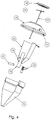
- a first embodiment of a wastewater treatment system 1 is shown in Figure 1 .
- the wastewater treatment system 1 generally comprises an outer tank or carcass 10, a cover 15 with a lid 18.
- An aeration chamber 20 is mounted within the carcass 10 and, in turn, has within it a draft tube 25 and a diffuser assembly 27 and 28.
- the treatment system 1 also includes an inlet or influent pipe 31 and an outlet or effluent pipe 32.
- the carcass 10 is a unitary, one-piece component preferably, but not exclusively, formed of glass-reinforced plastic (GRP).
- GRP glass-reinforced plastic
- the height of the carcass 10 (base to inlet pipe) is preferably between 1.5 m and 5 m, more preferably between 2 m and 3.8 m and has a maximum outside diameter between 1 m and 5 m, more preferably 1.5 m and 3.5 m. At these sizes the carcass 10 has a capacity of between 2,000 litres and 15,000 litres.
- the carcass 10 is generally symmetrical about a central vertically extending axis with a generally circular cross-section orthogonal to the central axis.
- the carcass 10 is open at its upper edge and at its bottom edge is closed with a base that is small relative to the diameter of its open upper edge.
- the carcass 10 comprises three sections: a lower section, an intermediate section 11 and an upper section 12.
- the wall profile of the lower section is generally an inverted cone with the internal diameter of the lower section increasing towards the upper edge.
- the intermediate section 11 extends upwardly from the top edge of the lower section and similarly has an inverted conical wall profile but with an opening angle ( ⁇ 5°) which is significantly smaller than the opening angle of the lower section.
- the upper section 12, which extends upwardly from the top edge of the intermediate section 11, may also have an inverted conical wall profile or may be generally cylindrical. In both cases, however, the upper section 12 has a slightly larger internal diameter than the diameter of the intermediate section 11 at its top edge so that the junction between the intermediate section 11 and the upper section 12 is in the form of a circumferential shoulder.
- the upper section 12 also includes two apertures or ports 13a, 13b which are described in greater detail below.
- the upper rim 14 of the upper section 12 has the same or a slightly larger internal diameter in comparison to the diameter of the top edge of the intermediate section 11.
- the rim 14 also includes one or more circumferentially spaced notches (not shown) in the upper edge of the rim 14.
- the carcass 10 has a completely free internal space with no integral internal structure or other internal projections. Also, the carcass 10 has a substantially smooth external surface with no structure(s) projecting outwardly from the outer wall of the carcass intermediate the ends of the carcass. As a result a plurality of identical carcasses 10 can be intimately stacked, one inside the other, for substantially the entire length of each carcass. Where the upper section 12 is generally cylindrical, a second carcass can be stacked within a first carcass with only the upper section of the second carcass projecting beyond the rim 14 of the first carcass. Alternatively where the upper section 12 is conical, even less of the second carcass may project beyond the rim of the first carcass.
- the cover 15 is used to close the upper opening of the carcass 10 and preferably is domed.
- the cover has a lower rim 16 with a diameter sufficiently slightly greater than the diameter of the carcass rim 14 to provide a sliding fit between the carcass rim 14 and the cover rim 16.
- the cover rim 16 may also include one or more circumferentially spaced notches 17 which may be aligned with the notches in the carcass rim.
- the top of the cover 15 has a generally cylindrical aperture which is closed by a removable lid 18.
- the removable lid 18 is sized to provide access to the interior of the carcass 10 so that the cover 15 need not be removed after installation.
- the cover 15 may optionally include an access point 19 in the form of a frangible area which may be opened to provide an aperture for cabling, for example.
- the aeration chamber 20 is preferably a unitary one-piece component formed of GRP and is substantially symmetrical about a vertically extending axis.
- the aeration chamber 20, which encloses a biologically active zone, is open at both its lower edge 21 and its upper edge 23, with the diameter of the lower edge opening 21 being smaller than the diameter of the upper edge opening 23.
- the aeration chamber 20 has an upper section 22a and a lower section 22b with each section 22a, 22b having a generally conical wall tapering towards the lower edge 21 of the chamber but with the opening angle of the lower section 22b being much greater than the opening angle of the upper section 22a.
- the aeration chamber 20 has a completely free internal space with an integral internal inner space with substantially no internal structure. Projecting radially outwardly from the upper edge 23 of the aeration chamber 20 are a plurality of arms 24 (three arms are shown in Figure 3 .
- the free end of each arm 24 has in a downwardly directed lip 24' which is positioned at a radial position slightly greater than the radius of the rim 14 of the carcass 10.
- the lip 24' is sized to fit within the notches provided in the rim 14 and the notches in the rim 16 of the cover 15.
- the outer surface of the aeration chamber 20 has no structure(s) projecting outwardly from the surface of the aeration chamber intermediate its two ends, this means that a plurality of aeration chambers 20 can be intimately stacked, one inside the other for substantially the entire length of each aeration chamber.
- the draft tube 25 is preferably formed of polyethylene and is substantially cylindrical with a diameter less than the diameter of the lower opening 21 of the aeration chamber 20.
- the draft tube 25 preferably has an axial length corresponding to at least 1.5 times the depth of the lower section 22b of the aeration chamber 20 and includes a plurality of outwardly projecting fins 26 (preferably three) circumferentially spaced around a central portion of the draft tube.
- Each of the fins 26 has an outer edge facing away from the central vertical axis and angled with respect to the central vertical axis so as to correspond with the tapering angle of the inner surface of the lower section 22b of the aeration chamber.
- the inner surface of the lower section 22b may include a series of shallow grooves or shallow protrusions (not shown) that define slots for engagement with the outer edge of each of the fins 26 so as to ensure accurate alignment of the draft tube within the aeration chamber 20.
- the diffuser 27 is a narrow hollow pipe for the delivery of gas, such as air, via a plurality of apertures in the diffuser head 28 to the bottom area of the wastewater treatment system.
- gas such as air
- the diffuser 27 is mounted within the draft tube 25 and is aligned with the central axis of the carcass 10.
- a supporting bar or mounting bracket 29 is provided from which the diffuser 27 hangs downwardly and an air supply inlet 30 such as an air hose connector.
- the mounting bracket 29 is adapted to be mounted to the inner surface of the cover 15 using conventional securing devices such as, but not limited, to nuts and bolts or screws. Alternatively the mounting bracket may be integral with the cover 15.
- the upper section 12 of the carcass includes two circular apertures 13a, 13b circumferentially spaced from one another and preferably circumferentially opposing each other. Also, ideally a first one of the apertures 13a is positioned higher (closer to the upper rim of the carcass) than the second aperture 13b.
- the apertures 13a, 13b are sized preferably to receive conventional influent 31 and effluent 32 pipes respectively and each aperture may additionally include a grommet or alternative sealing device for providing a fluid-tight seal between the edge of the aperture and the influent / effluent pipes.
- the effluent pipe 32 is a dip pipe or swept tee pipe with the inlet of the dip pipe extending downwardly into the region enclosed by the intermediate section 11 of the carcass.
- the carcass and the aeration chambers are stackable and 20-30 stacked wastewater treatment systems can be stored in a standard 40 ft. transportation container. This represents a significant saving in transportation costs and transportation carbon footprint in comparison with conventional wastewater treatment systems where a standard 40 ft. transportation container could only accommodate 5 equivalent wastewater treatment systems.
- the wastewater treatment system 1 is buried into the ground so that preferably only the lid 18 remains exposed and with the influent pipe connected to the sewage pipes of an adjacent sewage supply in a manner similar to conventional wastewater treatment systems.
- the diffuser 27 is connected to a supply of air via the air inlet 30 so as to feed air to the bottom of the treatment system. Sewage is fed into the interior of the aeration chamber 20 via the influent pipe 31. Within the draft tube 25 solid waste is mixed and lifted by the action of air supplied by the diffuser 27 into the aeration chamber 20 where oxygenation of the water encourages microbial activity to treat the waste trapped in the aeration chamber 20.
- Water which is substantially free of solid waste is able to escape from the aeration chamber 20 to the region between the aeration chamber and the carcass where it flows out from the wastewater treatment system via the effluent pipe 32.
- the wastewater treatment system does not require and does not have a weir or scum baffle.
- the treatment system 1 is designed to enable construction by one person and requires only a conventional screw driver or no tools. Construction is performed as follows:
- a pump chamber (not shown in the drawings) that may be mounted internally at or close to the rim 14 of the carcass 10.
- the pump chamber is used to house a pump mechanism, if required, and can be mounted to the carcass 10 using inter-engagement between one or more unitary constructional features of the carcass structure and one or more unitary constructional features of the pump chamber structure. In other words the pump chamber can be mounted to the carcass 10 without using any separate fixing components.
- the present invention provides an improved wastewater treatment system that is easier and quicker to construct and, being stackable, can be transported more efficiently and much more cheaply than conventional treatment systems.
Landscapes
- Life Sciences & Earth Sciences (AREA)
- Biodiversity & Conservation Biology (AREA)
- Microbiology (AREA)
- Hydrology & Water Resources (AREA)
- Engineering & Computer Science (AREA)
- Environmental & Geological Engineering (AREA)
- Water Supply & Treatment (AREA)
- Chemical & Material Sciences (AREA)
- Organic Chemistry (AREA)
- Biological Treatment Of Waste Water (AREA)
Claims (13)
- Abwasserbehandlungssystem, das Folgendes umfasst:einen Außentank (10), der an einem Ende (14) offen ist, und eine innere Belüftungskammer (20), die an einem ersten (21) und einem gegenüberliegenden zweiten (23) Ende offen ist,wobei sich der Innendurchmesser des Außentanks (10) in Richtung auf sein offenes Ende allgemein vergrößert, wobei der Außentank (10) mit anderen im Wesentlichen identischen Außentanks im Wesentlichen über seine gesamte Länge innig stapelbar ist und die Belüftungskammer (20) im Wesentlichen keine innere oder äußere Struktur hat, die von ihrer Wand zwischen dem ersten und zweiten Ende wegragt,
dadurch gekennzeichnet, dass der Außentank (10) im Wesentlichen keine innere Struktur hat; die Belüftungskammer (20) sich mit Bezug auf ihren Innendurchmesser von ihrem ersten Ende (21) zu ihrem gegenüberliegenden zweiten Ende (23) allgemein vergrößert und mit anderen im Wesentlichen identischen Belüftungskammern im Wesentlichen über ihre gesamte Länge innig stapelbar ist; und die innere Belüftungskammer (20) wenigstens einen Arm (24) aufweist, der sich vom zweiten Ende (23) der inneren Belüftungskammer (20) radial nach außen erstreckt, wobei der wenigstens eine Arm (24) am offenen Ende (14) des Außentanks (10) eingreift. - Abwasserbehandlungssystem nach Anspruch 1, wobei der Außentank (10) eine einheitliche Komponente ist und im Wesentlichen keine einheitlich damit ausgebildete innere Struktur hat.
- Abwasserbehandlungssystem nach Anspruch 1, wobei die Belüftungskammer (20) mehrere Arme (24) hat, die sich vom zweiten Ende (23) der Belüftungskammer (20) radial nach außen erstrecken und am offenen Ende (14) des Außentanks (10) eingreifen.
- Abwasserbehandlungssystem nach Anspruch 1 oder 3, wobei der wenigstens eine Arm (24) an seinem freien Ende eine Lippe (24') aufweist, die an einem Rand am offenen Ende (14) des Außentanks (10) eingreift, und das Abwasserbehandlungssystem ferner eine oder mehrere Halterungen für jede Lippe (24') beinhaltet, die die Lippe (24') am Rand des Außentanks (10) befestigen.
- Abwasserbehandlungssystem nach einem der Ansprüche 1 bis 4, wobei der wenigstens eine Arm (24) mit der Belüftungskammer einheitlich ausgebildet ist.
- Abwasserbehandlungssystem nach einem der vorhergehenden Ansprüche, das ferner ein Saugrohr (25) mit gegenüberliegenden ersten und zweiten offenen Enden umfasst, wobei das Saugrohr (25) mehrere Rippen (26) aufweist, die sich von der Rohrwand zwischen seinen gegenüberliegenden ersten und zweiten offenen Enden radial nach außen erstrecken.
- Abwasserbehandlungssystem nach Anspruch 6, wobei die freie Kante jeder Rippe (26) mit Bezug auf die Achse des Saugrohres (25) abgewinkelt ist und mit der konisch zulaufenden Innenfläche der Belüftungskammerwand (20) in Eingriff kommt.
- Abwasserbehandlungssystem nach einem der vorhergehenden Ansprüche, wobei der Außentank (10) eine Einlassöffnung (13a) und eine Auslassöffnung (13b) aufweist und das Abwasserbehandlungssystem ferner ein Tauchrohr (32) im Eingriff mit der Auslassöffnung (13b) beinhaltet.
- Abwasserbehandlungssystem nach einem der vorhergehenden Ansprüche, wobei das Behandlungssystem kein Wehr hat.
- Abwasserbehandlungssystem nach einem der vorhergehenden Ansprüche, wobei das Behandlungssystem keinen Schwimmschlammabstreifer hat.
- Abwasserbehandlungssystem nach einem der vorhergehenden Ansprüche, das ferner eine Abdeckung (15), die das offene Ende des Außentanks (10) verschließt, und ein Klebeband umfasst, das die Verbindungsstelle zwischen der Abdeckung (15) und dem Außentank (10) abdichtet.
- Abwasserbehandlungssystem nach einem der vorhergehenden Ansprüche, das ferner ein Luftzuführungssystem (27) zum Zuführen von Luft zum Boden des Außentanks (10) umfasst.
- Bausatz für ein Abwasserbehandlungssystem nach einem der Ansprüche 1 bis 12, wobei der Bausatz Folgendes umfasst: einen Außentank (10), der an einem Ende (14) offen ist, und eine innere Belüftungskammer (20), die an einem ersten (21) und einem gegenüberliegenden zweiten (23) Ende offen ist, wobei sich der Innendurchmesser des Außentanks (10) in Richtung auf sein offenes Ende (14) allgemein vergrößert, wobei der Außentank (10) mit anderen im Wesentlichen identischen Außentanks im Wesentlichen über seine gesamte Länge innig stapelbar ist und die Belüftungskammer (20) im Wesentlichen keine innere oder äußere Struktur hat, die von ihrer Wand zwischen dem ersten und zweiten Ende wegragt,
dadurch gekennzeichnet, dass der Außentank (10) im Wesentlichen keine innere Struktur hat; die Belüftungskammer (20) sich mit Bezug auf ihren Innendurchmesser von ihrem ersten Ende (21) zu ihrem gegenüberliegenden zweiten Ende (23) allgemein vergrößert und mit anderen im Wesentlichen identischen Belüftungskammern im Wesentlichen über ihre gesamte Länge innig stapelbar ist; und die innere Belüftungskammer (20) wenigstens einen Arm (24) aufweist, der sich vom zweiten Ende (23) der inneren Belüftungskammer (20) radial nach außen erstreckt, wobei der wenigstens eine Arm (24) am offenen Ende (14) des Außentanks (10) eingreift.
Applications Claiming Priority (3)
| Application Number | Priority Date | Filing Date | Title |
|---|---|---|---|
| GB201311249A GB201311249D0 (en) | 2013-06-24 | 2013-06-24 | Wastewater treatment system |
| GB201316618A GB2503377B (en) | 2013-06-24 | 2013-09-19 | Wastewater treatment system |
| PCT/GB2014/051584 WO2014207433A1 (en) | 2013-06-24 | 2014-05-22 | Wastewater treatment system comprising an outer tank and an inner aeration chamber |
Publications (2)
| Publication Number | Publication Date |
|---|---|
| EP3013757A1 EP3013757A1 (de) | 2016-05-04 |
| EP3013757B1 true EP3013757B1 (de) | 2020-02-12 |
Family
ID=48998891
Family Applications (1)
| Application Number | Title | Priority Date | Filing Date |
|---|---|---|---|
| EP14728608.2A Active EP3013757B1 (de) | 2013-06-24 | 2014-05-22 | Abwasserbehandlungssystem umfassend einen äusseren tank und eine innere belüftungskammer |
Country Status (4)
| Country | Link |
|---|---|
| EP (1) | EP3013757B1 (de) |
| DE (1) | DE212014000013U1 (de) |
| GB (2) | GB201311249D0 (de) |
| WO (1) | WO2014207433A1 (de) |
Families Citing this family (1)
| Publication number | Priority date | Publication date | Assignee | Title |
|---|---|---|---|---|
| PL74065Y1 (pl) * | 2018-12-12 | 2025-09-08 | Politechnika Rzeszowska Im Ignacego Lukasiewicza | Urządzenie do oczyszczania ścieków |
Family Cites Families (7)
| Publication number | Priority date | Publication date | Assignee | Title |
|---|---|---|---|---|
| JPS5763193A (en) * | 1980-09-30 | 1982-04-16 | Sekisui Chem Co Ltd | Sewage treatment device |
| MX9304141A (es) | 1992-07-22 | 1994-02-28 | Richard C Baxter | Aparato movil para el tratamiento de desechos. |
| AU696976B2 (en) * | 1997-03-03 | 1998-09-24 | Sep - Tech Industries Australia Pty Ltd | Effluent treatment |
| CN2672052Y (zh) * | 2004-02-10 | 2005-01-19 | 青岛绿保森环保设备有限公司 | 一种污水净化装置 |
| US7178677B1 (en) * | 2005-10-31 | 2007-02-20 | Jerry L. Mckinney 2002 Trust | Aeration vessel for use in aerobic wastewater treatment system |
| US7513994B2 (en) * | 2005-10-31 | 2009-04-07 | Jerry L. Mckinney 2002 Trust | Aeration vessel and aerator assembly for use in a wastewater treatment system |
| CA2761861C (en) * | 2009-05-15 | 2020-04-28 | Consolidated Treatment Systems, Inc. | Wastewater treatment system |
-
2013
- 2013-06-24 GB GB201311249A patent/GB201311249D0/en not_active Ceased
- 2013-09-19 GB GB201316618A patent/GB2503377B/en active Active
-
2014
- 2014-05-22 WO PCT/GB2014/051584 patent/WO2014207433A1/en not_active Ceased
- 2014-05-22 DE DE212014000013.0U patent/DE212014000013U1/de not_active Expired - Lifetime
- 2014-05-22 EP EP14728608.2A patent/EP3013757B1/de active Active
Non-Patent Citations (1)
| Title |
|---|
| None * |
Also Published As
| Publication number | Publication date |
|---|---|
| DE212014000013U1 (de) | 2015-05-15 |
| GB201316618D0 (en) | 2013-10-30 |
| GB2503377B (en) | 2014-08-06 |
| GB201311249D0 (en) | 2013-08-14 |
| GB2503377A (en) | 2013-12-25 |
| EP3013757A1 (de) | 2016-05-04 |
| WO2014207433A1 (en) | 2014-12-31 |
Similar Documents
| Publication | Publication Date | Title |
|---|---|---|
| US8137544B1 (en) | Waste water treatment system | |
| US7252766B2 (en) | Wastewater treatment system and method | |
| US6358411B1 (en) | Wastewater treatment plant | |
| ES2691042T3 (es) | Biofiltro para digestión de aguas residuales | |
| US8431019B2 (en) | Wastewater treatment system | |
| WO2014207433A1 (en) | Wastewater treatment system comprising an outer tank and an inner aeration chamber | |
| US7294261B2 (en) | Vessel assembly for use in a wastewater treatment system | |
| US6821415B2 (en) | Self-adjusting fluid surface skimmer and fluid treatment system using same | |
| US6814863B2 (en) | Radial flow septic tank | |
| US7767088B2 (en) | Water treatment clarifier baffle | |
| US20110168721A1 (en) | Transportable Wastewater Treatment Tank | |
| US7341660B1 (en) | Unitary three stage wastewater treatment system | |
| US5779896A (en) | Gas baffle for a waste water treatment plant effluent | |
| RU2714432C1 (ru) | Контейнер и биогазовая установка | |
| KR100574161B1 (ko) | 오버플로워관을 중앙지지대로하고 내부격벽형태를달리하여 기능성을 향상시킨 원통형유체저장탱크. | |
| US20060042174A1 (en) | Modular riser base | |
| US4268389A (en) | Sewage treatment | |
| CN103232109B (zh) | 多功能生物反应器 | |
| GB2280383A (en) | Gravity separator | |
| RU2820889C1 (ru) | Станция биологической очистки | |
| US10519055B1 (en) | Aerobic wastewater treatment systems and methods of fabrication | |
| CN216427046U (zh) | 一种三格式加强型化粪池 | |
| CN109179908B (zh) | 装配式a/o池及装配式污水处理系统 | |
| AU2017100759B4 (en) | Storage tank | |
| PL176200B1 (pl) | Sposób i urządzenie do mieszania płynnej biomasy w bioreaktorze, zwłaszcza w obecności mikroorganizmów mezofilnych i/lub termofilnych z równoczesnym uzyskiwaniem gazowego metanu |
Legal Events
| Date | Code | Title | Description |
|---|---|---|---|
| PUAI | Public reference made under article 153(3) epc to a published international application that has entered the european phase |
Free format text: ORIGINAL CODE: 0009012 |
|
| 17P | Request for examination filed |
Effective date: 20151217 |
|
| AK | Designated contracting states |
Kind code of ref document: A1 Designated state(s): AL AT BE BG CH CY CZ DE DK EE ES FI FR GB GR HR HU IE IS IT LI LT LU LV MC MK MT NL NO PL PT RO RS SE SI SK SM TR |
|
| AX | Request for extension of the european patent |
Extension state: BA ME |
|
| DAX | Request for extension of the european patent (deleted) | ||
| STAA | Information on the status of an ep patent application or granted ep patent |
Free format text: STATUS: EXAMINATION IS IN PROGRESS |
|
| 17Q | First examination report despatched |
Effective date: 20170124 |
|
| GRAP | Despatch of communication of intention to grant a patent |
Free format text: ORIGINAL CODE: EPIDOSNIGR1 |
|
| STAA | Information on the status of an ep patent application or granted ep patent |
Free format text: STATUS: GRANT OF PATENT IS INTENDED |
|
| INTG | Intention to grant announced |
Effective date: 20190827 |
|
| GRAS | Grant fee paid |
Free format text: ORIGINAL CODE: EPIDOSNIGR3 |
|
| GRAA | (expected) grant |
Free format text: ORIGINAL CODE: 0009210 |
|
| STAA | Information on the status of an ep patent application or granted ep patent |
Free format text: STATUS: THE PATENT HAS BEEN GRANTED |
|
| AK | Designated contracting states |
Kind code of ref document: B1 Designated state(s): AL AT BE BG CH CY CZ DE DK EE ES FI FR GB GR HR HU IE IS IT LI LT LU LV MC MK MT NL NO PL PT RO RS SE SI SK SM TR |
|
| REG | Reference to a national code |
Ref country code: GB Ref legal event code: FG4D |
|
| REG | Reference to a national code |
Ref country code: CH Ref legal event code: EP |
|
| REG | Reference to a national code |
Ref country code: AT Ref legal event code: REF Ref document number: 1231880 Country of ref document: AT Kind code of ref document: T Effective date: 20200215 |
|
| REG | Reference to a national code |
Ref country code: DE Ref legal event code: R096 Ref document number: 602014060865 Country of ref document: DE |
|
| REG | Reference to a national code |
Ref country code: IE Ref legal event code: FG4D |
|
| PG25 | Lapsed in a contracting state [announced via postgrant information from national office to epo] |
Ref country code: FI Free format text: LAPSE BECAUSE OF FAILURE TO SUBMIT A TRANSLATION OF THE DESCRIPTION OR TO PAY THE FEE WITHIN THE PRESCRIBED TIME-LIMIT Effective date: 20200212 Ref country code: NO Free format text: LAPSE BECAUSE OF FAILURE TO SUBMIT A TRANSLATION OF THE DESCRIPTION OR TO PAY THE FEE WITHIN THE PRESCRIBED TIME-LIMIT Effective date: 20200512 Ref country code: RS Free format text: LAPSE BECAUSE OF FAILURE TO SUBMIT A TRANSLATION OF THE DESCRIPTION OR TO PAY THE FEE WITHIN THE PRESCRIBED TIME-LIMIT Effective date: 20200212 |
|
| REG | Reference to a national code |
Ref country code: LT Ref legal event code: MG4D |
|
| REG | Reference to a national code |
Ref country code: NL Ref legal event code: MP Effective date: 20200212 |
|
| PG25 | Lapsed in a contracting state [announced via postgrant information from national office to epo] |
Ref country code: BG Free format text: LAPSE BECAUSE OF FAILURE TO SUBMIT A TRANSLATION OF THE DESCRIPTION OR TO PAY THE FEE WITHIN THE PRESCRIBED TIME-LIMIT Effective date: 20200512 Ref country code: LV Free format text: LAPSE BECAUSE OF FAILURE TO SUBMIT A TRANSLATION OF THE DESCRIPTION OR TO PAY THE FEE WITHIN THE PRESCRIBED TIME-LIMIT Effective date: 20200212 Ref country code: IS Free format text: LAPSE BECAUSE OF FAILURE TO SUBMIT A TRANSLATION OF THE DESCRIPTION OR TO PAY THE FEE WITHIN THE PRESCRIBED TIME-LIMIT Effective date: 20200612 Ref country code: SE Free format text: LAPSE BECAUSE OF FAILURE TO SUBMIT A TRANSLATION OF THE DESCRIPTION OR TO PAY THE FEE WITHIN THE PRESCRIBED TIME-LIMIT Effective date: 20200212 Ref country code: HR Free format text: LAPSE BECAUSE OF FAILURE TO SUBMIT A TRANSLATION OF THE DESCRIPTION OR TO PAY THE FEE WITHIN THE PRESCRIBED TIME-LIMIT Effective date: 20200212 Ref country code: GR Free format text: LAPSE BECAUSE OF FAILURE TO SUBMIT A TRANSLATION OF THE DESCRIPTION OR TO PAY THE FEE WITHIN THE PRESCRIBED TIME-LIMIT Effective date: 20200513 |
|
| PG25 | Lapsed in a contracting state [announced via postgrant information from national office to epo] |
Ref country code: NL Free format text: LAPSE BECAUSE OF FAILURE TO SUBMIT A TRANSLATION OF THE DESCRIPTION OR TO PAY THE FEE WITHIN THE PRESCRIBED TIME-LIMIT Effective date: 20200212 |
|
| PG25 | Lapsed in a contracting state [announced via postgrant information from national office to epo] |
Ref country code: CZ Free format text: LAPSE BECAUSE OF FAILURE TO SUBMIT A TRANSLATION OF THE DESCRIPTION OR TO PAY THE FEE WITHIN THE PRESCRIBED TIME-LIMIT Effective date: 20200212 Ref country code: DK Free format text: LAPSE BECAUSE OF FAILURE TO SUBMIT A TRANSLATION OF THE DESCRIPTION OR TO PAY THE FEE WITHIN THE PRESCRIBED TIME-LIMIT Effective date: 20200212 Ref country code: LT Free format text: LAPSE BECAUSE OF FAILURE TO SUBMIT A TRANSLATION OF THE DESCRIPTION OR TO PAY THE FEE WITHIN THE PRESCRIBED TIME-LIMIT Effective date: 20200212 Ref country code: SM Free format text: LAPSE BECAUSE OF FAILURE TO SUBMIT A TRANSLATION OF THE DESCRIPTION OR TO PAY THE FEE WITHIN THE PRESCRIBED TIME-LIMIT Effective date: 20200212 Ref country code: EE Free format text: LAPSE BECAUSE OF FAILURE TO SUBMIT A TRANSLATION OF THE DESCRIPTION OR TO PAY THE FEE WITHIN THE PRESCRIBED TIME-LIMIT Effective date: 20200212 Ref country code: SK Free format text: LAPSE BECAUSE OF FAILURE TO SUBMIT A TRANSLATION OF THE DESCRIPTION OR TO PAY THE FEE WITHIN THE PRESCRIBED TIME-LIMIT Effective date: 20200212 Ref country code: RO Free format text: LAPSE BECAUSE OF FAILURE TO SUBMIT A TRANSLATION OF THE DESCRIPTION OR TO PAY THE FEE WITHIN THE PRESCRIBED TIME-LIMIT Effective date: 20200212 Ref country code: ES Free format text: LAPSE BECAUSE OF FAILURE TO SUBMIT A TRANSLATION OF THE DESCRIPTION OR TO PAY THE FEE WITHIN THE PRESCRIBED TIME-LIMIT Effective date: 20200212 Ref country code: PT Free format text: LAPSE BECAUSE OF FAILURE TO SUBMIT A TRANSLATION OF THE DESCRIPTION OR TO PAY THE FEE WITHIN THE PRESCRIBED TIME-LIMIT Effective date: 20200705 |
|
| REG | Reference to a national code |
Ref country code: DE Ref legal event code: R097 Ref document number: 602014060865 Country of ref document: DE |
|
| REG | Reference to a national code |
Ref country code: AT Ref legal event code: MK05 Ref document number: 1231880 Country of ref document: AT Kind code of ref document: T Effective date: 20200212 |
|
| PLBE | No opposition filed within time limit |
Free format text: ORIGINAL CODE: 0009261 |
|
| STAA | Information on the status of an ep patent application or granted ep patent |
Free format text: STATUS: NO OPPOSITION FILED WITHIN TIME LIMIT |
|
| 26N | No opposition filed |
Effective date: 20201113 |
|
| PG25 | Lapsed in a contracting state [announced via postgrant information from national office to epo] |
Ref country code: CH Free format text: LAPSE BECAUSE OF NON-PAYMENT OF DUE FEES Effective date: 20200531 Ref country code: AT Free format text: LAPSE BECAUSE OF FAILURE TO SUBMIT A TRANSLATION OF THE DESCRIPTION OR TO PAY THE FEE WITHIN THE PRESCRIBED TIME-LIMIT Effective date: 20200212 Ref country code: LI Free format text: LAPSE BECAUSE OF NON-PAYMENT OF DUE FEES Effective date: 20200531 Ref country code: IT Free format text: LAPSE BECAUSE OF FAILURE TO SUBMIT A TRANSLATION OF THE DESCRIPTION OR TO PAY THE FEE WITHIN THE PRESCRIBED TIME-LIMIT Effective date: 20200212 Ref country code: MC Free format text: LAPSE BECAUSE OF FAILURE TO SUBMIT A TRANSLATION OF THE DESCRIPTION OR TO PAY THE FEE WITHIN THE PRESCRIBED TIME-LIMIT Effective date: 20200212 |
|
| PG25 | Lapsed in a contracting state [announced via postgrant information from national office to epo] |
Ref country code: PL Free format text: LAPSE BECAUSE OF FAILURE TO SUBMIT A TRANSLATION OF THE DESCRIPTION OR TO PAY THE FEE WITHIN THE PRESCRIBED TIME-LIMIT Effective date: 20200212 Ref country code: SI Free format text: LAPSE BECAUSE OF FAILURE TO SUBMIT A TRANSLATION OF THE DESCRIPTION OR TO PAY THE FEE WITHIN THE PRESCRIBED TIME-LIMIT Effective date: 20200212 |
|
| REG | Reference to a national code |
Ref country code: BE Ref legal event code: MM Effective date: 20200531 |
|
| PG25 | Lapsed in a contracting state [announced via postgrant information from national office to epo] |
Ref country code: LU Free format text: LAPSE BECAUSE OF NON-PAYMENT OF DUE FEES Effective date: 20200522 |
|
| PG25 | Lapsed in a contracting state [announced via postgrant information from national office to epo] |
Ref country code: IE Free format text: LAPSE BECAUSE OF NON-PAYMENT OF DUE FEES Effective date: 20200522 |
|
| PG25 | Lapsed in a contracting state [announced via postgrant information from national office to epo] |
Ref country code: BE Free format text: LAPSE BECAUSE OF NON-PAYMENT OF DUE FEES Effective date: 20200531 |
|
| PG25 | Lapsed in a contracting state [announced via postgrant information from national office to epo] |
Ref country code: TR Free format text: LAPSE BECAUSE OF FAILURE TO SUBMIT A TRANSLATION OF THE DESCRIPTION OR TO PAY THE FEE WITHIN THE PRESCRIBED TIME-LIMIT Effective date: 20200212 Ref country code: MT Free format text: LAPSE BECAUSE OF FAILURE TO SUBMIT A TRANSLATION OF THE DESCRIPTION OR TO PAY THE FEE WITHIN THE PRESCRIBED TIME-LIMIT Effective date: 20200212 Ref country code: CY Free format text: LAPSE BECAUSE OF FAILURE TO SUBMIT A TRANSLATION OF THE DESCRIPTION OR TO PAY THE FEE WITHIN THE PRESCRIBED TIME-LIMIT Effective date: 20200212 |
|
| PG25 | Lapsed in a contracting state [announced via postgrant information from national office to epo] |
Ref country code: MK Free format text: LAPSE BECAUSE OF FAILURE TO SUBMIT A TRANSLATION OF THE DESCRIPTION OR TO PAY THE FEE WITHIN THE PRESCRIBED TIME-LIMIT Effective date: 20200212 Ref country code: AL Free format text: LAPSE BECAUSE OF FAILURE TO SUBMIT A TRANSLATION OF THE DESCRIPTION OR TO PAY THE FEE WITHIN THE PRESCRIBED TIME-LIMIT Effective date: 20200212 |
|
| PGFP | Annual fee paid to national office [announced via postgrant information from national office to epo] |
Ref country code: DE Payment date: 20220428 Year of fee payment: 9 |
|
| REG | Reference to a national code |
Ref country code: DE Ref legal event code: R119 Ref document number: 602014060865 Country of ref document: DE |
|
| REG | Reference to a national code |
Ref country code: DE Ref legal event code: R082 Ref document number: 602014060865 Country of ref document: DE Representative=s name: KRAUS & LEDERER PARTGMBB, DE |
|
| PG25 | Lapsed in a contracting state [announced via postgrant information from national office to epo] |
Ref country code: DE Free format text: LAPSE BECAUSE OF NON-PAYMENT OF DUE FEES Effective date: 20231201 |
|
| PGFP | Annual fee paid to national office [announced via postgrant information from national office to epo] |
Ref country code: GB Payment date: 20250527 Year of fee payment: 12 |
|
| PGFP | Annual fee paid to national office [announced via postgrant information from national office to epo] |
Ref country code: FR Payment date: 20250528 Year of fee payment: 12 |