EP3013562B1 - Verfahren zum stoffschlüssigen verbinden von faserverstärkten bauteilen - Google Patents
Verfahren zum stoffschlüssigen verbinden von faserverstärkten bauteilen Download PDFInfo
- Publication number
- EP3013562B1 EP3013562B1 EP14738427.5A EP14738427A EP3013562B1 EP 3013562 B1 EP3013562 B1 EP 3013562B1 EP 14738427 A EP14738427 A EP 14738427A EP 3013562 B1 EP3013562 B1 EP 3013562B1
- Authority
- EP
- European Patent Office
- Prior art keywords
- components
- sonotrode
- die
- joined
- active surface
- Prior art date
- Legal status (The legal status is an assumption and is not a legal conclusion. Google has not performed a legal analysis and makes no representation as to the accuracy of the status listed.)
- Active
Links
Images
Classifications
-
- B—PERFORMING OPERATIONS; TRANSPORTING
- B29—WORKING OF PLASTICS; WORKING OF SUBSTANCES IN A PLASTIC STATE IN GENERAL
- B29C—SHAPING OR JOINING OF PLASTICS; SHAPING OF MATERIAL IN A PLASTIC STATE, NOT OTHERWISE PROVIDED FOR; AFTER-TREATMENT OF THE SHAPED PRODUCTS, e.g. REPAIRING
- B29C65/00—Joining or sealing of preformed parts, e.g. welding of plastics materials; Apparatus therefor
- B29C65/02—Joining or sealing of preformed parts, e.g. welding of plastics materials; Apparatus therefor by heating, with or without pressure
- B29C65/08—Joining or sealing of preformed parts, e.g. welding of plastics materials; Apparatus therefor by heating, with or without pressure using ultrasonic vibrations
-
- B—PERFORMING OPERATIONS; TRANSPORTING
- B29—WORKING OF PLASTICS; WORKING OF SUBSTANCES IN A PLASTIC STATE IN GENERAL
- B29C—SHAPING OR JOINING OF PLASTICS; SHAPING OF MATERIAL IN A PLASTIC STATE, NOT OTHERWISE PROVIDED FOR; AFTER-TREATMENT OF THE SHAPED PRODUCTS, e.g. REPAIRING
- B29C66/00—General aspects of processes or apparatus for joining preformed parts
- B29C66/01—General aspects dealing with the joint area or with the area to be joined
- B29C66/05—Particular design of joint configurations
- B29C66/10—Particular design of joint configurations particular design of the joint cross-sections
- B29C66/11—Joint cross-sections comprising a single joint-segment, i.e. one of the parts to be joined comprising a single joint-segment in the joint cross-section
- B29C66/112—Single lapped joints
- B29C66/1122—Single lap to lap joints, i.e. overlap joints
-
- B—PERFORMING OPERATIONS; TRANSPORTING
- B29—WORKING OF PLASTICS; WORKING OF SUBSTANCES IN A PLASTIC STATE IN GENERAL
- B29C—SHAPING OR JOINING OF PLASTICS; SHAPING OF MATERIAL IN A PLASTIC STATE, NOT OTHERWISE PROVIDED FOR; AFTER-TREATMENT OF THE SHAPED PRODUCTS, e.g. REPAIRING
- B29C66/00—General aspects of processes or apparatus for joining preformed parts
- B29C66/40—General aspects of joining substantially flat articles, e.g. plates, sheets or web-like materials; Making flat seams in tubular or hollow articles; Joining single elements to substantially flat surfaces
- B29C66/41—Joining substantially flat articles ; Making flat seams in tubular or hollow articles
- B29C66/43—Joining a relatively small portion of the surface of said articles
-
- B—PERFORMING OPERATIONS; TRANSPORTING
- B29—WORKING OF PLASTICS; WORKING OF SUBSTANCES IN A PLASTIC STATE IN GENERAL
- B29C—SHAPING OR JOINING OF PLASTICS; SHAPING OF MATERIAL IN A PLASTIC STATE, NOT OTHERWISE PROVIDED FOR; AFTER-TREATMENT OF THE SHAPED PRODUCTS, e.g. REPAIRING
- B29C66/00—General aspects of processes or apparatus for joining preformed parts
- B29C66/70—General aspects of processes or apparatus for joining preformed parts characterised by the composition, physical properties or the structure of the material of the parts to be joined; Joining with non-plastics material
- B29C66/72—General aspects of processes or apparatus for joining preformed parts characterised by the composition, physical properties or the structure of the material of the parts to be joined; Joining with non-plastics material characterised by the structure of the material of the parts to be joined
- B29C66/721—Fibre-reinforced materials
-
- B—PERFORMING OPERATIONS; TRANSPORTING
- B29—WORKING OF PLASTICS; WORKING OF SUBSTANCES IN A PLASTIC STATE IN GENERAL
- B29C—SHAPING OR JOINING OF PLASTICS; SHAPING OF MATERIAL IN A PLASTIC STATE, NOT OTHERWISE PROVIDED FOR; AFTER-TREATMENT OF THE SHAPED PRODUCTS, e.g. REPAIRING
- B29C66/00—General aspects of processes or apparatus for joining preformed parts
- B29C66/70—General aspects of processes or apparatus for joining preformed parts characterised by the composition, physical properties or the structure of the material of the parts to be joined; Joining with non-plastics material
- B29C66/73—General aspects of processes or apparatus for joining preformed parts characterised by the composition, physical properties or the structure of the material of the parts to be joined; Joining with non-plastics material characterised by the intensive physical properties of the material of the parts to be joined, by the optical properties of the material of the parts to be joined, by the extensive physical properties of the parts to be joined, by the state of the material of the parts to be joined or by the material of the parts to be joined being a thermoplastic or a thermoset
- B29C66/739—General aspects of processes or apparatus for joining preformed parts characterised by the composition, physical properties or the structure of the material of the parts to be joined; Joining with non-plastics material characterised by the intensive physical properties of the material of the parts to be joined, by the optical properties of the material of the parts to be joined, by the extensive physical properties of the parts to be joined, by the state of the material of the parts to be joined or by the material of the parts to be joined being a thermoplastic or a thermoset characterised by the material of the parts to be joined being a thermoplastic or a thermoset
- B29C66/7392—General aspects of processes or apparatus for joining preformed parts characterised by the composition, physical properties or the structure of the material of the parts to be joined; Joining with non-plastics material characterised by the intensive physical properties of the material of the parts to be joined, by the optical properties of the material of the parts to be joined, by the extensive physical properties of the parts to be joined, by the state of the material of the parts to be joined or by the material of the parts to be joined being a thermoplastic or a thermoset characterised by the material of the parts to be joined being a thermoplastic or a thermoset characterised by the material of at least one of the parts being a thermoplastic
- B29C66/73921—General aspects of processes or apparatus for joining preformed parts characterised by the composition, physical properties or the structure of the material of the parts to be joined; Joining with non-plastics material characterised by the intensive physical properties of the material of the parts to be joined, by the optical properties of the material of the parts to be joined, by the extensive physical properties of the parts to be joined, by the state of the material of the parts to be joined or by the material of the parts to be joined being a thermoplastic or a thermoset characterised by the material of the parts to be joined being a thermoplastic or a thermoset characterised by the material of at least one of the parts being a thermoplastic characterised by the materials of both parts being thermoplastics
-
- B—PERFORMING OPERATIONS; TRANSPORTING
- B29—WORKING OF PLASTICS; WORKING OF SUBSTANCES IN A PLASTIC STATE IN GENERAL
- B29C—SHAPING OR JOINING OF PLASTICS; SHAPING OF MATERIAL IN A PLASTIC STATE, NOT OTHERWISE PROVIDED FOR; AFTER-TREATMENT OF THE SHAPED PRODUCTS, e.g. REPAIRING
- B29C66/00—General aspects of processes or apparatus for joining preformed parts
- B29C66/80—General aspects of machine operations or constructions and parts thereof
- B29C66/81—General aspects of the pressing elements, i.e. the elements applying pressure on the parts to be joined in the area to be joined, e.g. the welding jaws or clamps
- B29C66/814—General aspects of the pressing elements, i.e. the elements applying pressure on the parts to be joined in the area to be joined, e.g. the welding jaws or clamps characterised by the design of the pressing elements, e.g. of the welding jaws or clamps
- B29C66/8141—General aspects of the pressing elements, i.e. the elements applying pressure on the parts to be joined in the area to be joined, e.g. the welding jaws or clamps characterised by the design of the pressing elements, e.g. of the welding jaws or clamps characterised by the surface geometry of the part of the pressing elements, e.g. welding jaws or clamps, coming into contact with the parts to be joined
- B29C66/81411—General aspects of the pressing elements, i.e. the elements applying pressure on the parts to be joined in the area to be joined, e.g. the welding jaws or clamps characterised by the design of the pressing elements, e.g. of the welding jaws or clamps characterised by the surface geometry of the part of the pressing elements, e.g. welding jaws or clamps, coming into contact with the parts to be joined characterised by its cross-section, e.g. transversal or longitudinal, being non-flat
- B29C66/81421—General aspects of the pressing elements, i.e. the elements applying pressure on the parts to be joined in the area to be joined, e.g. the welding jaws or clamps characterised by the design of the pressing elements, e.g. of the welding jaws or clamps characterised by the surface geometry of the part of the pressing elements, e.g. welding jaws or clamps, coming into contact with the parts to be joined characterised by its cross-section, e.g. transversal or longitudinal, being non-flat being convex or concave
- B29C66/81422—General aspects of the pressing elements, i.e. the elements applying pressure on the parts to be joined in the area to be joined, e.g. the welding jaws or clamps characterised by the design of the pressing elements, e.g. of the welding jaws or clamps characterised by the surface geometry of the part of the pressing elements, e.g. welding jaws or clamps, coming into contact with the parts to be joined characterised by its cross-section, e.g. transversal or longitudinal, being non-flat being convex or concave being convex
-
- B—PERFORMING OPERATIONS; TRANSPORTING
- B29—WORKING OF PLASTICS; WORKING OF SUBSTANCES IN A PLASTIC STATE IN GENERAL
- B29C—SHAPING OR JOINING OF PLASTICS; SHAPING OF MATERIAL IN A PLASTIC STATE, NOT OTHERWISE PROVIDED FOR; AFTER-TREATMENT OF THE SHAPED PRODUCTS, e.g. REPAIRING
- B29C66/00—General aspects of processes or apparatus for joining preformed parts
- B29C66/80—General aspects of machine operations or constructions and parts thereof
- B29C66/81—General aspects of the pressing elements, i.e. the elements applying pressure on the parts to be joined in the area to be joined, e.g. the welding jaws or clamps
- B29C66/814—General aspects of the pressing elements, i.e. the elements applying pressure on the parts to be joined in the area to be joined, e.g. the welding jaws or clamps characterised by the design of the pressing elements, e.g. of the welding jaws or clamps
- B29C66/8141—General aspects of the pressing elements, i.e. the elements applying pressure on the parts to be joined in the area to be joined, e.g. the welding jaws or clamps characterised by the design of the pressing elements, e.g. of the welding jaws or clamps characterised by the surface geometry of the part of the pressing elements, e.g. welding jaws or clamps, coming into contact with the parts to be joined
- B29C66/81411—General aspects of the pressing elements, i.e. the elements applying pressure on the parts to be joined in the area to be joined, e.g. the welding jaws or clamps characterised by the design of the pressing elements, e.g. of the welding jaws or clamps characterised by the surface geometry of the part of the pressing elements, e.g. welding jaws or clamps, coming into contact with the parts to be joined characterised by its cross-section, e.g. transversal or longitudinal, being non-flat
- B29C66/81421—General aspects of the pressing elements, i.e. the elements applying pressure on the parts to be joined in the area to be joined, e.g. the welding jaws or clamps characterised by the design of the pressing elements, e.g. of the welding jaws or clamps characterised by the surface geometry of the part of the pressing elements, e.g. welding jaws or clamps, coming into contact with the parts to be joined characterised by its cross-section, e.g. transversal or longitudinal, being non-flat being convex or concave
- B29C66/81423—General aspects of the pressing elements, i.e. the elements applying pressure on the parts to be joined in the area to be joined, e.g. the welding jaws or clamps characterised by the design of the pressing elements, e.g. of the welding jaws or clamps characterised by the surface geometry of the part of the pressing elements, e.g. welding jaws or clamps, coming into contact with the parts to be joined characterised by its cross-section, e.g. transversal or longitudinal, being non-flat being convex or concave being concave
-
- B—PERFORMING OPERATIONS; TRANSPORTING
- B29—WORKING OF PLASTICS; WORKING OF SUBSTANCES IN A PLASTIC STATE IN GENERAL
- B29C—SHAPING OR JOINING OF PLASTICS; SHAPING OF MATERIAL IN A PLASTIC STATE, NOT OTHERWISE PROVIDED FOR; AFTER-TREATMENT OF THE SHAPED PRODUCTS, e.g. REPAIRING
- B29C66/00—General aspects of processes or apparatus for joining preformed parts
- B29C66/80—General aspects of machine operations or constructions and parts thereof
- B29C66/81—General aspects of the pressing elements, i.e. the elements applying pressure on the parts to be joined in the area to be joined, e.g. the welding jaws or clamps
- B29C66/814—General aspects of the pressing elements, i.e. the elements applying pressure on the parts to be joined in the area to be joined, e.g. the welding jaws or clamps characterised by the design of the pressing elements, e.g. of the welding jaws or clamps
- B29C66/8141—General aspects of the pressing elements, i.e. the elements applying pressure on the parts to be joined in the area to be joined, e.g. the welding jaws or clamps characterised by the design of the pressing elements, e.g. of the welding jaws or clamps characterised by the surface geometry of the part of the pressing elements, e.g. welding jaws or clamps, coming into contact with the parts to be joined
- B29C66/81427—General aspects of the pressing elements, i.e. the elements applying pressure on the parts to be joined in the area to be joined, e.g. the welding jaws or clamps characterised by the design of the pressing elements, e.g. of the welding jaws or clamps characterised by the surface geometry of the part of the pressing elements, e.g. welding jaws or clamps, coming into contact with the parts to be joined comprising a single ridge, e.g. for making a weakening line; comprising a single tooth
-
- B—PERFORMING OPERATIONS; TRANSPORTING
- B29—WORKING OF PLASTICS; WORKING OF SUBSTANCES IN A PLASTIC STATE IN GENERAL
- B29C—SHAPING OR JOINING OF PLASTICS; SHAPING OF MATERIAL IN A PLASTIC STATE, NOT OTHERWISE PROVIDED FOR; AFTER-TREATMENT OF THE SHAPED PRODUCTS, e.g. REPAIRING
- B29C66/00—General aspects of processes or apparatus for joining preformed parts
- B29C66/80—General aspects of machine operations or constructions and parts thereof
- B29C66/81—General aspects of the pressing elements, i.e. the elements applying pressure on the parts to be joined in the area to be joined, e.g. the welding jaws or clamps
- B29C66/814—General aspects of the pressing elements, i.e. the elements applying pressure on the parts to be joined in the area to be joined, e.g. the welding jaws or clamps characterised by the design of the pressing elements, e.g. of the welding jaws or clamps
- B29C66/8141—General aspects of the pressing elements, i.e. the elements applying pressure on the parts to be joined in the area to be joined, e.g. the welding jaws or clamps characterised by the design of the pressing elements, e.g. of the welding jaws or clamps characterised by the surface geometry of the part of the pressing elements, e.g. welding jaws or clamps, coming into contact with the parts to be joined
- B29C66/81431—General aspects of the pressing elements, i.e. the elements applying pressure on the parts to be joined in the area to be joined, e.g. the welding jaws or clamps characterised by the design of the pressing elements, e.g. of the welding jaws or clamps characterised by the surface geometry of the part of the pressing elements, e.g. welding jaws or clamps, coming into contact with the parts to be joined comprising a single cavity, e.g. a groove
-
- B—PERFORMING OPERATIONS; TRANSPORTING
- B29—WORKING OF PLASTICS; WORKING OF SUBSTANCES IN A PLASTIC STATE IN GENERAL
- B29C—SHAPING OR JOINING OF PLASTICS; SHAPING OF MATERIAL IN A PLASTIC STATE, NOT OTHERWISE PROVIDED FOR; AFTER-TREATMENT OF THE SHAPED PRODUCTS, e.g. REPAIRING
- B29C66/00—General aspects of processes or apparatus for joining preformed parts
- B29C66/80—General aspects of machine operations or constructions and parts thereof
- B29C66/83—General aspects of machine operations or constructions and parts thereof characterised by the movement of the joining or pressing tools
- B29C66/832—Reciprocating joining or pressing tools
- B29C66/8322—Joining or pressing tools reciprocating along one axis
-
- B—PERFORMING OPERATIONS; TRANSPORTING
- B29—WORKING OF PLASTICS; WORKING OF SUBSTANCES IN A PLASTIC STATE IN GENERAL
- B29C—SHAPING OR JOINING OF PLASTICS; SHAPING OF MATERIAL IN A PLASTIC STATE, NOT OTHERWISE PROVIDED FOR; AFTER-TREATMENT OF THE SHAPED PRODUCTS, e.g. REPAIRING
- B29C66/00—General aspects of processes or apparatus for joining preformed parts
- B29C66/80—General aspects of machine operations or constructions and parts thereof
- B29C66/83—General aspects of machine operations or constructions and parts thereof characterised by the movement of the joining or pressing tools
- B29C66/832—Reciprocating joining or pressing tools
- B29C66/8322—Joining or pressing tools reciprocating along one axis
- B29C66/83221—Joining or pressing tools reciprocating along one axis cooperating reciprocating tools, each tool reciprocating along one axis
-
- B—PERFORMING OPERATIONS; TRANSPORTING
- B29—WORKING OF PLASTICS; WORKING OF SUBSTANCES IN A PLASTIC STATE IN GENERAL
- B29C—SHAPING OR JOINING OF PLASTICS; SHAPING OF MATERIAL IN A PLASTIC STATE, NOT OTHERWISE PROVIDED FOR; AFTER-TREATMENT OF THE SHAPED PRODUCTS, e.g. REPAIRING
- B29C66/00—General aspects of processes or apparatus for joining preformed parts
- B29C66/70—General aspects of processes or apparatus for joining preformed parts characterised by the composition, physical properties or the structure of the material of the parts to be joined; Joining with non-plastics material
- B29C66/72—General aspects of processes or apparatus for joining preformed parts characterised by the composition, physical properties or the structure of the material of the parts to be joined; Joining with non-plastics material characterised by the structure of the material of the parts to be joined
- B29C66/721—Fibre-reinforced materials
- B29C66/7212—Fibre-reinforced materials characterised by the composition of the fibres
-
- B—PERFORMING OPERATIONS; TRANSPORTING
- B29—WORKING OF PLASTICS; WORKING OF SUBSTANCES IN A PLASTIC STATE IN GENERAL
- B29C—SHAPING OR JOINING OF PLASTICS; SHAPING OF MATERIAL IN A PLASTIC STATE, NOT OTHERWISE PROVIDED FOR; AFTER-TREATMENT OF THE SHAPED PRODUCTS, e.g. REPAIRING
- B29C66/00—General aspects of processes or apparatus for joining preformed parts
- B29C66/70—General aspects of processes or apparatus for joining preformed parts characterised by the composition, physical properties or the structure of the material of the parts to be joined; Joining with non-plastics material
- B29C66/73—General aspects of processes or apparatus for joining preformed parts characterised by the composition, physical properties or the structure of the material of the parts to be joined; Joining with non-plastics material characterised by the intensive physical properties of the material of the parts to be joined, by the optical properties of the material of the parts to be joined, by the extensive physical properties of the parts to be joined, by the state of the material of the parts to be joined or by the material of the parts to be joined being a thermoplastic or a thermoset
- B29C66/739—General aspects of processes or apparatus for joining preformed parts characterised by the composition, physical properties or the structure of the material of the parts to be joined; Joining with non-plastics material characterised by the intensive physical properties of the material of the parts to be joined, by the optical properties of the material of the parts to be joined, by the extensive physical properties of the parts to be joined, by the state of the material of the parts to be joined or by the material of the parts to be joined being a thermoplastic or a thermoset characterised by the material of the parts to be joined being a thermoplastic or a thermoset
- B29C66/7392—General aspects of processes or apparatus for joining preformed parts characterised by the composition, physical properties or the structure of the material of the parts to be joined; Joining with non-plastics material characterised by the intensive physical properties of the material of the parts to be joined, by the optical properties of the material of the parts to be joined, by the extensive physical properties of the parts to be joined, by the state of the material of the parts to be joined or by the material of the parts to be joined being a thermoplastic or a thermoset characterised by the material of the parts to be joined being a thermoplastic or a thermoset characterised by the material of at least one of the parts being a thermoplastic
Definitions
- the present invention relates to a method for the integral connection of fiber-reinforced components.
- Ultrasonic welding is described in the prior art for joining thermoplastic materials.
- the workpieces are heated locally until they are in a viscous state.
- the materials of the individual workpieces flow into one another at the joint and connect the workpieces cohesively.
- the thermal energy required to join the workpieces is generated by mechanical vibrations. These vibrations are in the range of ultrasonic frequencies.
- WO2007 / 123943 shows a further prior art according to the preamble of claim 1.
- the device has a die for receiving the components to be connected, the die having its own active surface facing the active surface of the snonotrode.
- the active surface of the sonotrode and the active surface of the die can each be a shaping active surface which can be formed at least in sections with one of the components to be connected.
- the sonotrode can be designed as an ultrasound sonotrode.
- the shape of the active surface of the sonotrode and the shape of the active surface of the die can be complementary. If, for example, the active surface of the sonotrode is convex, the active surface of the die has a concave shape and vice versa. As a result, the components to be joined are not squeezed in their direction of thickness, as in the prior art, but rather are formed uniformly while maintaining their original thickness.
- the active surface can be convex or concave curved at least in sections and / or have a combination of convex and concave curvatures. This offers the advantage that particularly smooth transitions from the unwelded material to the welded material can be produced in the joining zone, which further increase the strength of the joining zone.
- the active surface of the sonotrode can have a protruding area, with a cup-shaped, cup-shaped, hemispherical and / or conical cross-sectional shape. These shapes have been found to be particularly gentle on the fibers and are particularly well suited for shaping the sonotrode or as a negative shape for the die.
- the active surface can have rounded edge regions.
- This method therefore offers the advantage that higher connection strengths are generated by the additional positive locking in the joint.
- the reinforcing fibers are protected in the joining zone, which further improves the mechanical strength.
- connection and the forming of the components can be carried out simultaneously.
- fiber-reinforced components are plastic components with a matrix, in particular a matrix made of thermoplastic, in which fibers are embedded for reinforcement.
- These fibers can be designed as glass, carbon, aramid and / or basalt fibers.
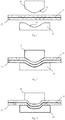
- Figure 1 shows a sonotrode 11 with an active surface 13 and a die 12 with an active surface 14.
- the active surface 13 and the active surface 14 face one another and lie opposite one another.
- the shape of the active surface 13 is convex and thus complementary to that of the active surface 14, which is curved concavely.
- the sonotrode 11 and the die 12 can be moved relative to one another.
- Both tool halves 11, 12 can be designed to be movable. Alternatively, only the sonotrode can be moved towards the die or only the die towards the sonotrode. In these cases, the immovable tool half is then fixed and the movable half is designed to be displaceable.
- the sonotrode 11 and the die 12 are components of a welding system, not shown.
- the components 21 and 22 to be joined are shown between the sonotrode 11 and the die 12.
- the welding system is transferred to a welding position, the sonotrode 11 and the die 12 moving toward one another, so that the components 21, 22 to be joined are clamped or deformed between them.
- the sonotrode 11 is set in ultrasonic vibrations, the sonotrode being able to perform movements towards and away from the die.
- Such movements correspond in Figure 2 an oscillating upward and downward movement and are essentially perpendicular to the parting plane of the tool halves 11, 12.
- the sonotrode 11 can also perform lateral movements in order to connect the two components 21 and 22 in a friction-welding manner by means of ultrasound.
- the sonotrode 11 oscillates essentially in the parting plane or in a plane of the tool halves 11, 12 parallel to the parting plane Figures 1, 2 and 3 is the Sonotrode 11 is shown as the upper tool half and the die 12 as the lower tool half. According to the invention, the position of the die 12 and the position of the sonotrode 11 can be interchanged.
- FIG 3 an alternative embodiment of the joining device is shown.
- the active surface 13 of the sonotrode 11 and the active surface 14 of the die 12 have a combination of convex and concave curvatures.
- a cup-shaped protruding region 15 is shown in the center of the active surface 13 of the sonotrode 11.
- a particularly good undercut can be produced at the joint of the two components 21, 22, since the projecting region 15 presses the upper component 21 deeper into the component 22 below.
- the transitions from the flat areas of the active surface 13 to the protruding area 15 are rounded, so that there are no discontinuities in the edges. Edges would change the course of the reinforcement fibers accordingly and reduce the flow of force. There is also a risk that the fibers will be damaged by edges.
Landscapes
- Engineering & Computer Science (AREA)
- Mechanical Engineering (AREA)
- Lining Or Joining Of Plastics Or The Like (AREA)
Description
- Die vorliegende Erfindung betrifft ein Verfahren zum stoffschlüssigen Verbinden von faserverstärkten Bauteilen.
- Zum Fügen von thermoplastischen Kunststoffen wird im Stand der Technik das Ultraschall-Schweißen beschrieben. Dabei werden die Werkstücke lokal erwärmt, bis sie sich in einen zähflüssigen Zustand befinden. Die Materialien der einzelnen Werkstücke fließen an der Fügestelle ineinander und verbinden die Werkstücke stoffschlüssig. Die Wärmeenergie, die zum Fügen der Werkstücke benötigt wird, wird durch mechanische Schwingungen erzeugt. Diese Schwingungen liegen im Bereich von Ultraschallfrequenzen.
- Ein Beispiel einer solchen Sonotrode für eine Ultraschall-Schweißanlage ist aus der europäischen Patentschrift
EP 1 250 996 B1 bekannt. Die aus dem Stand der Technik bekannten Sonotroden-Formen berücksichtigen nicht die speziellen Anforderungen von faserverstärkten Kunststoffbauteilen. Beim klassischen Fügen mittels Ultraschall-Punktschweißen mit Dorn-Sonotrode werden die zu fügenden Bauteile geschwächt, d.h. in ihren Dicken reduziert. In manchen Fällen bleibt sogar ein Loch in einem der zu fügenden Bauteile zurück, wodurch sich die erreichbare Verbindungsfestigkeit reduziert. -
WO2007/123943 zeigt ein weiterer Stand der Technik nach dem Oberbegriff von Anspruch 1. - Ausgehend von diesem Stand der Technik macht es sich die vorliegende Erfindung zur Aufgabe, ein vereinfachtes Verfahren anzugeben, mit dem die Nachteile des Standes der Technik überwunden werden. Ferner ist es Aufgabe der Erfindung, ein Verfahren zum Fügen von faserverstärkten Kunststoffbauteilen anzugeben, mit dem bzw. der besonders hohe mechanische Eigenschaften in der Verbindungsstelle erzeugt werden.
- Diese Aufgabe wird durch ein Verfahren mit den Merkmalen des unabhängigen Anspruchs 1 gelöst. Die abhängigen Ansprüche stellen vorteilhafte Ausführungsformen der vorliegenden Erfindung dar.
- Darüber hinaus weist die Vorrichtung eine Matrize, zur Aufnahme der zu verbindenden Bauteile auf, wobei die Matrize eine der Wirkfläche der Snonotrode zugewandte eigene Wirkoberfläche aufweist. Weiterhin kann die Wirkfläche der Sonotrode und die Wirkoberfläche der Matrize jeweils eine formgebende Wirkfläche sein, die mit einem der zu verbindenden Bauteile zumindest abschnittsweise formbar ist. Dadurch zeichnet sich beim Verschweißen der Bauteile die Wirkfläche des der Sonotrode und die Wirkoberfläche der Matrize jeweils in der Oberfläche des Bauteils ab, mit dem die Sonotrode bzw. die Matrize in berührenden Kontakt kommt. Dies bietet den Vorteil, dass die vorgeschlagenen Sonotrodenformen bzw. die Matrize wie Gegenwerkzeuge fungieren, mit denen eine Verbindung ähnlich eines Clinchpunktes wie in der Metallfügetechnik bekannt, erzeugbar ist.
- Darüber hinaus kann die Sonotrode als eine Ultraschall-Sonotrode ausgebildet sein. Zusätzlich oder alternativ kann die Form der Wirkfläche der Sonotrode und die Form der Wirkoberfläche der Matrize komplementär ausgebildet sein. Wenn beispielsweise die Wirkfläche der Sonotrode konvex geformt ist, weist die Wirkoberfläche der Matrize eine konkave Form auf und umgekehrt. Dadurch werden die zu fügenden Bauteile in ihrer Dickenrichtung nicht, wie im Stand der Technik, gequetscht sondern gleichmäßig unter Beibehaltung ihrer ursprünglichen Dicke umgeformt.
- Dadurch kann im Bereich der Fügestelle die mechanische Festigkeit der zu fügenden Bauteile aufrecht erhalten werden, wobei weitestgehend die Fasern geschont werden.
- Darüber hinaus kann die Wirkfläche zumindest abschnittsweise konvex oder konkav gekrümmt sein und/oder eine Kombination aus konvexen und konkaven Krümmungen aufweisen. Dies bietet den Vorteil, dass besonders weiche Übergänge vom unverschweißten Material zu dem verschweißten Material in der Fügezone erzeugt werden können, durch die die Festigkeit der Fügezone weiter erhöht wird.
- Darüber hinaus kann die Wirkfläche der Sonotrode einen hervorspringenden Bereich aufweisen, mit einer topfförmigen, napfförmigen, halbkugelförmigen und/oder kegelförmigen Querschnittsform aufweisen. Diese genannten Formen haben sich als besonders faserschonend herausgestellt und sind besonders gut geeignet zur Formung der Sonotrode bzw. als Negativ-Form für die Matrize.
- Zusätzlich kann die Wirkfläche abgerundete Kantenbereiche aufweisen.
- Dieses Verfahren bietet somit den Vorteil, dass höhere Verbindungsfestigkeiten durch den zusätzlichen Formschluss in der Fügestelle erzeugt werden. Darüber hinaus werden die Verstärkungsfasern in der Fügezone geschont, wodurch sich die mechanische Festigkeit weiter verbessert.
- Besonders gute Eigenschaften werden erreicht, wenn die Sonotrode zum Fügen der Bauteile in einem Ultraschall-Frequenzbereich betrieben wird.
- Darüber hinaus kann das stoffschlüssige Verbinden und das Umformen der Bauteile simultan erfolgen.
- In Sinne dieser Erfindung sind faserverstärkte Bauteile, Kunststoffbauteile mit einer Matrix, insbesondere einer Matrix aus thermoplastischem Kunststoff, in der zur Verstärkung Fasern eingebettet sind. Diese Fasern können als Glas-, Kohlenstoff-, Aramid- und/oder Basaltfasern ausgebildet sein.
- Im Folgenden wird die Erfindung anhand der Figurenbeschreibung näher erläutert. Die Ansprüche, die Figuren und die Beschreibung enthalten eine Vielzahl von Merkmalen, die im Folgenden im Zusammenhang mit beispielhaft beschriebenen Ausführungsformen der vorliegenden Erfindung erläutert werden. Der Fachmann wird diese Merkmale auch einzeln und in anderen Kombinationen betrachten, um weitere Ausführungsformen zu bilden, die an entsprechende Anwendungen der Erfindung angepasst sind.
- Fig. 1
- eine Ausgangssituation zum Fügen zweier faserverstärkter Kunststoffbauteile,
- Fig. 2
- eine Endposition, bei der die zu fügenden Bauteile umgeformt sind und
- Fig. 3
- eine alternative Ausführungsform in der Endposition des Verfahrens.
-
Figur 1 zeigt eine Sonotrode 11 mit einer Wirkfläche 13 und eine Matrize 12 mit einer Wirkoberfläche 14. Die Wirkfläche 13 und die Wirkoberfläche 14 sind einander zugewandt und liegen einander gegenüber. Die Form der Wirkfläche 13 ist konvex geformt und damit komplementär zu der der Wirkoberfläche 14, die konkav gebogen ist. Die Sonotrode 11 und die Matrize 12 können relativ zueinander bewegt werden. Dabei kann beide Werkzeughälften 11, 12 beweglich ausgebildet sein. Alternativ dazu kann auch nur die Sonotrode auf die Matrize oder nur die Matrize auf die Sonotrode zubewegt werden. In diesen Fällen ist dann die unbewegliche Werkzeughälfte fest und die bewegliche verschiebbar ausgebildet. - Die Sonotrode 11 und die Matrize 12 sind Bestandteile einer weiter nicht dargestellten Schweißanlage. Zwischen der Sonotrode 11 und der Matrize 12 sind die zu fügenden Bauteile 21 und 22 dargestellt.
- Zum Verschweißen der Bauteile 21, 22 wird die Schweißanlage in eine Schweißposition überführt, wobei die Sonotrode 11 und die Matrize 12 aufeinander zubewegt, so dass die zu fügenden Bauteile 21, 22 dazwischen geklemmt bzw. umgeformt werden. In dieser Position wird die Sonotrode 11 in UltraschallSchwingungen versetzt, wobei die Sonotrode Bewegungen auf die Matrize zu und von der Matrize weg durchführen kann. Solche Bewegungen entsprechen in
Figur 2 einer oszillierenden Auf- und Abwärtsbewegung und stehen im Wesentlichen senkrecht zur Trennebene der Werkzeughälften 11, 12. Alternativ dazu kann die Sonotrode 11 auch seitliche Bewegungen durchführen, um mittels Ultraschall die beiden Bauteile 21 und 22 reibschweißend zu verbinden. Dabei oszilliert die Sonotrode 11 in Wesentlichen in der Trennebene oder in einer zur Trennebene parallelen Ebene der Werkzeughälften 11, 12. In denFiguren 1, 2 und 3 ist die Sonotrode 11 als obere Werkzeughälfte und die Matrize 12 als untere Werkzeughälfte dargestellt. Erfindungsgemäß können die Position der Matrize 12 und die Position der Sonotrode 11 vertauscht werden. - In
Figur 3 ist eine alternative Ausführungsform der Fügevorrichtung dargestellt. Wie daraus ersichtlich weist die Wirkfläche 13 der Sonotrode 11 und die Wirkoberfläche 14 der Matrize 12 eine Kombination aus konvexen und konkaven Krümmungen auf. Mittig in der Wirkfläche 13 der Sonotrode 11 ist ein napfförmig hervorspringender Bereich 15 dargestellt. Dadurch kann an der Fügestelle der beiden Bauteile 21, 22 ein besonders guter Hinterschnitt erzeugt werden, da der hervorspringende Bereich 15 das obere Bauteil 21 tiefer in das unter Bauteil 22 drückt. Die Übergänge von den ebenen Bereichen der Wirkfläche 13 zu dem hervorspringenden Bereich 15 sind abgerundet, damit keine Stetigkeitssprünge an Kanten entstehen. Kanten würden den Verlauf der Verstärkungsfasern entsprechend verändern und den Kraftfluss reduzieren. Ferner besteht die Gefahr, dass durch Kanten die Fasern beschädigt werden.
Claims (3)
- Verfahren zum Fügen von faserverstärkten Kunststoffbauteilen mit den Schritten:- Anordnen der zu fügenden Bauteile (21, 22) zwischen einer Sonotrode (11) und einer Matrize (12),- stoffschlüssiges Verbinden der zu fügenden Bauteile durch Beaufschlagen der Bauteile (11, 12) mit Temperatur,- Umformen der zu fügenden Bauteile (21, 22) in einem Kontaktbereich, in dem die zu fügenden Bauteile mit der Sonotrode (11) auf die Matrize (12) gepresst werden,wobei
sich die Form der Wirkfläche (13) der Sonotrode (11) in einer der Bauteiloberflächen abbildet, dadurch gekennzeichnet, dass die zu fügenden Bauteile (21, 22) unter Beibehaltung ihrer ursprünglichen Dicke umgeformt werden. - Verfahren nach Anspruch 1, dadurch gekennzeichnet, dass die Sonotrode (11) eine Ultraschallsonotrode ist.
- Verfahren nach einem der Ansprüche 1 oder 2, dadurch gekennzeichnet, dass das stoffschlüssige Verbinden und das Umformen der Bauteile simultan erfolgt.
Applications Claiming Priority (2)
| Application Number | Priority Date | Filing Date | Title |
|---|---|---|---|
| DE102013212763.4A DE102013212763A1 (de) | 2013-06-28 | 2013-06-28 | Vorrichtung und Verfahren zum stoffschlüssigen Verbinden von faserverstärkten Bauteilen |
| PCT/EP2014/063272 WO2014206980A1 (de) | 2013-06-28 | 2014-06-24 | Vorrichtung und verfahren zum stoffschlüssigen verbinden von faserverstärkten bauteilen |
Publications (2)
| Publication Number | Publication Date |
|---|---|
| EP3013562A1 EP3013562A1 (de) | 2016-05-04 |
| EP3013562B1 true EP3013562B1 (de) | 2020-04-22 |
Family
ID=51176343
Family Applications (1)
| Application Number | Title | Priority Date | Filing Date |
|---|---|---|---|
| EP14738427.5A Active EP3013562B1 (de) | 2013-06-28 | 2014-06-24 | Verfahren zum stoffschlüssigen verbinden von faserverstärkten bauteilen |
Country Status (3)
| Country | Link |
|---|---|
| EP (1) | EP3013562B1 (de) |
| DE (1) | DE102013212763A1 (de) |
| WO (1) | WO2014206980A1 (de) |
Families Citing this family (2)
| Publication number | Priority date | Publication date | Assignee | Title |
|---|---|---|---|---|
| US10399175B2 (en) * | 2014-08-15 | 2019-09-03 | GM Global Technology Operations LLC | Systems and methods for improving weld strength |
| DE102017212326B4 (de) | 2017-07-19 | 2025-12-31 | Bayerische Motoren Werke Aktiengesellschaft | Verfahren zum Herstellen eines Metallbauteils sowie Metallbauteil |
Family Cites Families (12)
| Publication number | Priority date | Publication date | Assignee | Title |
|---|---|---|---|---|
| GB2168002B (en) * | 1984-12-06 | 1988-06-08 | Rolls Royce | Composite material manufacture |
| FR2802461A1 (fr) * | 1999-12-15 | 2001-06-22 | Polymat | Presse de thermoformage pour la mise en forme de tapis, en particulier de tapis de sol pour automobiles |
| DK1241100T3 (da) * | 2001-03-12 | 2004-05-03 | Tetra Laval Holdings & Finance | Ultrasonisk tværforseglingsfremgangsmåde og ultrasonisk tværforseglingsindretning til forsegling af vægge af et emballeringsmateriale fyldt med en hældbar fødevare |
| ES2266335T3 (es) | 2001-04-21 | 2007-03-01 | Plastal Gmbh | Sonotrodo para una instalacion de soldadura por ultrasonidos. |
| JP2005052983A (ja) * | 2003-08-04 | 2005-03-03 | Showa Denko Plastic Products Co Ltd | 超音波シール機および超音波シール方法 |
| JP4175478B2 (ja) * | 2005-04-28 | 2008-11-05 | 横浜ゴム株式会社 | 空気入りタイヤ及びその製造方法 |
| FR2887800B1 (fr) * | 2005-07-04 | 2011-02-11 | Eads Ccr Groupement Dinteret Economique | Procede d'assemblage par ultrasons d'au moins deux pieces rigides |
| WO2007123943A2 (en) * | 2006-04-18 | 2007-11-01 | Axya Medical Inc. | Multicomponent fused suture loop and apparatus for making same |
| DE102008011411A1 (de) * | 2008-02-27 | 2009-09-10 | Airbus Deutschland Gmbh | Verformungs-Vorrichtung zur Herstellung profilierter Halbzeuge, Anlage mit einer solchen Verformungs-Vorrichtung und Verfahren zur Herstellung profilierter Halbzeuge |
| DE102008059142A1 (de) * | 2008-11-26 | 2010-06-02 | Kunststoff-Zentrum in Leipzig gemeinnützige Gesellschaft mbH | Verfahren zum Fügen von verstärkten Polytetrafluorethylen-Folien mittels Ultraschall und Sonotrode zur Durchführung des Verfahrens |
| ES2566658T3 (es) * | 2010-01-18 | 2016-04-14 | Airbus Helicopters Deutschland GmbH | Proceso de fabricación de una pieza de material compuesto que comprende una capa de acabado funcional |
| DE102010039003B4 (de) * | 2010-08-06 | 2014-01-16 | Telesonic Holding Ag | Vorrichtung zum Verschweißen und Prägen dünnwandiger Werkstücke mittels Ultraschall |
-
2013
- 2013-06-28 DE DE102013212763.4A patent/DE102013212763A1/de not_active Ceased
-
2014
- 2014-06-24 EP EP14738427.5A patent/EP3013562B1/de active Active
- 2014-06-24 WO PCT/EP2014/063272 patent/WO2014206980A1/de not_active Ceased
Non-Patent Citations (1)
| Title |
|---|
| None * |
Also Published As
| Publication number | Publication date |
|---|---|
| EP3013562A1 (de) | 2016-05-04 |
| DE102013212763A1 (de) | 2014-12-31 |
| WO2014206980A1 (de) | 2014-12-31 |
Similar Documents
| Publication | Publication Date | Title |
|---|---|---|
| EP0150785B1 (de) | Verfahren zum Verbinden von Borsten mit einem Borstenträger | |
| DE69502716T2 (de) | Oszillierendes reibungsschweissen | |
| EP2219803B1 (de) | Verfahren zur herstellung geschweisster rund- und profilketten, kettenglied für eine rund- oder profilkette sowie aus solchen kettengliedern aufgebaute rund- oder profilkette | |
| DE69625894T2 (de) | Verfahren zum verbinden von hohlplatten aus kunststoffharz | |
| DE112006001867B4 (de) | Verbindungsvorrichtung und ein -verfahren für Metallplatten | |
| DE102011054362A9 (de) | Verbundblechteil mit metallischem Randbereich | |
| WO2015022174A1 (de) | Verfahren zur herstellung eines bauteils aus organoblechen | |
| DE3817119A1 (de) | Verbundbefestigungsvorrichtungen und verfahren zur befestigung von bauteilen damit | |
| EP2788169B1 (de) | Verbindungsanordnung eines faserverbund-bauteils mit einem zweiten bauteil | |
| EP1902811A1 (de) | Verbindung eines einen galvanischen Überzug aus Aluminium aufweisenden Befestigungselements aus Stahl mit einem flächigen Bauteil aus Aluminium | |
| EP3096935B1 (de) | Verfahren zum fügen von faserverstärktem kunststoffmaterial | |
| DE102015005407A1 (de) | Rührreibschweißen von Thermoplasten | |
| DE102015120717A1 (de) | Systeme und Verfahren zur Reduktion der Bildung von Lufteinschlüssen beim Schweissen | |
| DE102011116515B4 (de) | Ansaugkrümmerzusammenbau | |
| DE102013211580A1 (de) | Verfahren zum Verbinden von flächigen oder profilartigen Strukturen aus thermoplastischen Faserverbundkunststoffen mit metallischen Strukturen | |
| DE102009018151A1 (de) | Verfahren zum Fügen eines Metallkörpers mit einem Kunststoffkörper | |
| DE102011051301A1 (de) | Verfahren und Vorrichtung zur Herstellung einer Metall-Kunststoff-Verbindung | |
| DE102014204113A1 (de) | Kunststoff-Kompositstruktur und Verfahren zu deren Herstellung | |
| DE19918516C2 (de) | Verfahren zum Verbinden mindestens zweier flächiger Bauteile | |
| DE102009023717B4 (de) | Verfahren und Vorrichtung zur Herstellunq eines hybriden Werkstoffverbundes aus mehreren Füqepartnern und damit hergestellter hybrider Werkstoffverbund | |
| WO2014206980A1 (de) | Vorrichtung und verfahren zum stoffschlüssigen verbinden von faserverstärkten bauteilen | |
| EP2246178B1 (de) | Anbauteil zur Verbindung mit einem Bauteil durch torsionales Ultraschallschweißen | |
| DE102013020082A1 (de) | Schweißhilfsfügeteil, Matrize zum Setzen des Schweißhilfsfügeteils, ein Verbindungsverfahren für das Schweißhilfsfügeteil sowie Herstellungsverfahren für das Schweißhilfsfügeteil und die Matrize | |
| DE19750067B4 (de) | Verfahren zum Fügen eines Bauteils an einen Hohlkörper und dadurch herstellbarer Halter-Rohrelement-Komplex | |
| DE102016112437B4 (de) | Verfahren zur herstellung eines abschlussteils mittels ultraschallschweissens |
Legal Events
| Date | Code | Title | Description |
|---|---|---|---|
| PUAI | Public reference made under article 153(3) epc to a published international application that has entered the european phase |
Free format text: ORIGINAL CODE: 0009012 |
|
| 17P | Request for examination filed |
Effective date: 20160114 |
|
| AK | Designated contracting states |
Kind code of ref document: A1 Designated state(s): AL AT BE BG CH CY CZ DE DK EE ES FI FR GB GR HR HU IE IS IT LI LT LU LV MC MK MT NL NO PL PT RO RS SE SI SK SM TR |
|
| AX | Request for extension of the european patent |
Extension state: BA ME |
|
| DAX | Request for extension of the european patent (deleted) | ||
| STAA | Information on the status of an ep patent application or granted ep patent |
Free format text: STATUS: EXAMINATION IS IN PROGRESS |
|
| 17Q | First examination report despatched |
Effective date: 20190227 |
|
| GRAP | Despatch of communication of intention to grant a patent |
Free format text: ORIGINAL CODE: EPIDOSNIGR1 |
|
| STAA | Information on the status of an ep patent application or granted ep patent |
Free format text: STATUS: GRANT OF PATENT IS INTENDED |
|
| INTG | Intention to grant announced |
Effective date: 20200110 |
|
| RIN1 | Information on inventor provided before grant (corrected) |
Inventor name: MANTEI, INGO Inventor name: BRAUCH, MICHAEL |
|
| GRAS | Grant fee paid |
Free format text: ORIGINAL CODE: EPIDOSNIGR3 |
|
| GRAA | (expected) grant |
Free format text: ORIGINAL CODE: 0009210 |
|
| STAA | Information on the status of an ep patent application or granted ep patent |
Free format text: STATUS: THE PATENT HAS BEEN GRANTED |
|
| AK | Designated contracting states |
Kind code of ref document: B1 Designated state(s): AL AT BE BG CH CY CZ DE DK EE ES FI FR GB GR HR HU IE IS IT LI LT LU LV MC MK MT NL NO PL PT RO RS SE SI SK SM TR |
|
| REG | Reference to a national code |
Ref country code: CH Ref legal event code: EP |
|
| REG | Reference to a national code |
Ref country code: DE Ref legal event code: R096 Ref document number: 502014014043 Country of ref document: DE |
|
| REG | Reference to a national code |
Ref country code: IE Ref legal event code: FG4D Free format text: LANGUAGE OF EP DOCUMENT: GERMAN |
|
| REG | Reference to a national code |
Ref country code: AT Ref legal event code: REF Ref document number: 1259529 Country of ref document: AT Kind code of ref document: T Effective date: 20200515 |
|
| REG | Reference to a national code |
Ref country code: LT Ref legal event code: MG4D |
|
| REG | Reference to a national code |
Ref country code: NL Ref legal event code: MP Effective date: 20200422 |
|
| PG25 | Lapsed in a contracting state [announced via postgrant information from national office to epo] |
Ref country code: PT Free format text: LAPSE BECAUSE OF FAILURE TO SUBMIT A TRANSLATION OF THE DESCRIPTION OR TO PAY THE FEE WITHIN THE PRESCRIBED TIME-LIMIT Effective date: 20200824 Ref country code: GR Free format text: LAPSE BECAUSE OF FAILURE TO SUBMIT A TRANSLATION OF THE DESCRIPTION OR TO PAY THE FEE WITHIN THE PRESCRIBED TIME-LIMIT Effective date: 20200723 Ref country code: NO Free format text: LAPSE BECAUSE OF FAILURE TO SUBMIT A TRANSLATION OF THE DESCRIPTION OR TO PAY THE FEE WITHIN THE PRESCRIBED TIME-LIMIT Effective date: 20200722 Ref country code: NL Free format text: LAPSE BECAUSE OF FAILURE TO SUBMIT A TRANSLATION OF THE DESCRIPTION OR TO PAY THE FEE WITHIN THE PRESCRIBED TIME-LIMIT Effective date: 20200422 Ref country code: LT Free format text: LAPSE BECAUSE OF FAILURE TO SUBMIT A TRANSLATION OF THE DESCRIPTION OR TO PAY THE FEE WITHIN THE PRESCRIBED TIME-LIMIT Effective date: 20200422 Ref country code: IS Free format text: LAPSE BECAUSE OF FAILURE TO SUBMIT A TRANSLATION OF THE DESCRIPTION OR TO PAY THE FEE WITHIN THE PRESCRIBED TIME-LIMIT Effective date: 20200822 Ref country code: SE Free format text: LAPSE BECAUSE OF FAILURE TO SUBMIT A TRANSLATION OF THE DESCRIPTION OR TO PAY THE FEE WITHIN THE PRESCRIBED TIME-LIMIT Effective date: 20200422 Ref country code: FI Free format text: LAPSE BECAUSE OF FAILURE TO SUBMIT A TRANSLATION OF THE DESCRIPTION OR TO PAY THE FEE WITHIN THE PRESCRIBED TIME-LIMIT Effective date: 20200422 |
|
| PG25 | Lapsed in a contracting state [announced via postgrant information from national office to epo] |
Ref country code: HR Free format text: LAPSE BECAUSE OF FAILURE TO SUBMIT A TRANSLATION OF THE DESCRIPTION OR TO PAY THE FEE WITHIN THE PRESCRIBED TIME-LIMIT Effective date: 20200422 Ref country code: LV Free format text: LAPSE BECAUSE OF FAILURE TO SUBMIT A TRANSLATION OF THE DESCRIPTION OR TO PAY THE FEE WITHIN THE PRESCRIBED TIME-LIMIT Effective date: 20200422 Ref country code: BG Free format text: LAPSE BECAUSE OF FAILURE TO SUBMIT A TRANSLATION OF THE DESCRIPTION OR TO PAY THE FEE WITHIN THE PRESCRIBED TIME-LIMIT Effective date: 20200722 Ref country code: RS Free format text: LAPSE BECAUSE OF FAILURE TO SUBMIT A TRANSLATION OF THE DESCRIPTION OR TO PAY THE FEE WITHIN THE PRESCRIBED TIME-LIMIT Effective date: 20200422 |
|
| PG25 | Lapsed in a contracting state [announced via postgrant information from national office to epo] |
Ref country code: AL Free format text: LAPSE BECAUSE OF FAILURE TO SUBMIT A TRANSLATION OF THE DESCRIPTION OR TO PAY THE FEE WITHIN THE PRESCRIBED TIME-LIMIT Effective date: 20200422 |
|
| REG | Reference to a national code |
Ref country code: DE Ref legal event code: R097 Ref document number: 502014014043 Country of ref document: DE |
|
| PG25 | Lapsed in a contracting state [announced via postgrant information from national office to epo] |
Ref country code: ES Free format text: LAPSE BECAUSE OF FAILURE TO SUBMIT A TRANSLATION OF THE DESCRIPTION OR TO PAY THE FEE WITHIN THE PRESCRIBED TIME-LIMIT Effective date: 20200422 Ref country code: MC Free format text: LAPSE BECAUSE OF FAILURE TO SUBMIT A TRANSLATION OF THE DESCRIPTION OR TO PAY THE FEE WITHIN THE PRESCRIBED TIME-LIMIT Effective date: 20200422 Ref country code: CZ Free format text: LAPSE BECAUSE OF FAILURE TO SUBMIT A TRANSLATION OF THE DESCRIPTION OR TO PAY THE FEE WITHIN THE PRESCRIBED TIME-LIMIT Effective date: 20200422 Ref country code: SM Free format text: LAPSE BECAUSE OF FAILURE TO SUBMIT A TRANSLATION OF THE DESCRIPTION OR TO PAY THE FEE WITHIN THE PRESCRIBED TIME-LIMIT Effective date: 20200422 Ref country code: RO Free format text: LAPSE BECAUSE OF FAILURE TO SUBMIT A TRANSLATION OF THE DESCRIPTION OR TO PAY THE FEE WITHIN THE PRESCRIBED TIME-LIMIT Effective date: 20200422 Ref country code: DK Free format text: LAPSE BECAUSE OF FAILURE TO SUBMIT A TRANSLATION OF THE DESCRIPTION OR TO PAY THE FEE WITHIN THE PRESCRIBED TIME-LIMIT Effective date: 20200422 Ref country code: EE Free format text: LAPSE BECAUSE OF FAILURE TO SUBMIT A TRANSLATION OF THE DESCRIPTION OR TO PAY THE FEE WITHIN THE PRESCRIBED TIME-LIMIT Effective date: 20200422 Ref country code: IT Free format text: LAPSE BECAUSE OF FAILURE TO SUBMIT A TRANSLATION OF THE DESCRIPTION OR TO PAY THE FEE WITHIN THE PRESCRIBED TIME-LIMIT Effective date: 20200422 |
|
| REG | Reference to a national code |
Ref country code: CH Ref legal event code: PL |
|
| PG25 | Lapsed in a contracting state [announced via postgrant information from national office to epo] |
Ref country code: PL Free format text: LAPSE BECAUSE OF FAILURE TO SUBMIT A TRANSLATION OF THE DESCRIPTION OR TO PAY THE FEE WITHIN THE PRESCRIBED TIME-LIMIT Effective date: 20200422 Ref country code: SK Free format text: LAPSE BECAUSE OF FAILURE TO SUBMIT A TRANSLATION OF THE DESCRIPTION OR TO PAY THE FEE WITHIN THE PRESCRIBED TIME-LIMIT Effective date: 20200422 |
|
| PLBE | No opposition filed within time limit |
Free format text: ORIGINAL CODE: 0009261 |
|
| STAA | Information on the status of an ep patent application or granted ep patent |
Free format text: STATUS: NO OPPOSITION FILED WITHIN TIME LIMIT |
|
| 26N | No opposition filed |
Effective date: 20210125 |
|
| PG25 | Lapsed in a contracting state [announced via postgrant information from national office to epo] |
Ref country code: LU Free format text: LAPSE BECAUSE OF NON-PAYMENT OF DUE FEES Effective date: 20200624 |
|
| REG | Reference to a national code |
Ref country code: BE Ref legal event code: MM Effective date: 20200630 |
|
| PG25 | Lapsed in a contracting state [announced via postgrant information from national office to epo] |
Ref country code: IE Free format text: LAPSE BECAUSE OF NON-PAYMENT OF DUE FEES Effective date: 20200624 Ref country code: LI Free format text: LAPSE BECAUSE OF NON-PAYMENT OF DUE FEES Effective date: 20200630 Ref country code: CH Free format text: LAPSE BECAUSE OF NON-PAYMENT OF DUE FEES Effective date: 20200630 |
|
| PG25 | Lapsed in a contracting state [announced via postgrant information from national office to epo] |
Ref country code: BE Free format text: LAPSE BECAUSE OF NON-PAYMENT OF DUE FEES Effective date: 20200630 Ref country code: SI Free format text: LAPSE BECAUSE OF FAILURE TO SUBMIT A TRANSLATION OF THE DESCRIPTION OR TO PAY THE FEE WITHIN THE PRESCRIBED TIME-LIMIT Effective date: 20200422 |
|
| REG | Reference to a national code |
Ref country code: AT Ref legal event code: MM01 Ref document number: 1259529 Country of ref document: AT Kind code of ref document: T Effective date: 20200624 |
|
| PG25 | Lapsed in a contracting state [announced via postgrant information from national office to epo] |
Ref country code: AT Free format text: LAPSE BECAUSE OF NON-PAYMENT OF DUE FEES Effective date: 20200624 |
|
| PG25 | Lapsed in a contracting state [announced via postgrant information from national office to epo] |
Ref country code: TR Free format text: LAPSE BECAUSE OF FAILURE TO SUBMIT A TRANSLATION OF THE DESCRIPTION OR TO PAY THE FEE WITHIN THE PRESCRIBED TIME-LIMIT Effective date: 20200422 Ref country code: MT Free format text: LAPSE BECAUSE OF FAILURE TO SUBMIT A TRANSLATION OF THE DESCRIPTION OR TO PAY THE FEE WITHIN THE PRESCRIBED TIME-LIMIT Effective date: 20200422 Ref country code: CY Free format text: LAPSE BECAUSE OF FAILURE TO SUBMIT A TRANSLATION OF THE DESCRIPTION OR TO PAY THE FEE WITHIN THE PRESCRIBED TIME-LIMIT Effective date: 20200422 |
|
| PG25 | Lapsed in a contracting state [announced via postgrant information from national office to epo] |
Ref country code: MK Free format text: LAPSE BECAUSE OF FAILURE TO SUBMIT A TRANSLATION OF THE DESCRIPTION OR TO PAY THE FEE WITHIN THE PRESCRIBED TIME-LIMIT Effective date: 20200422 |
|
| P01 | Opt-out of the competence of the unified patent court (upc) registered |
Effective date: 20230502 |
|
| PGFP | Annual fee paid to national office [announced via postgrant information from national office to epo] |
Ref country code: DE Payment date: 20250605 Year of fee payment: 12 |
|
| PGFP | Annual fee paid to national office [announced via postgrant information from national office to epo] |
Ref country code: GB Payment date: 20250620 Year of fee payment: 12 |
|
| PGFP | Annual fee paid to national office [announced via postgrant information from national office to epo] |
Ref country code: FR Payment date: 20250618 Year of fee payment: 12 |