EP3013204B1 - Vacuum cleaner with electrostatic filter - Google Patents
Vacuum cleaner with electrostatic filter Download PDFInfo
- Publication number
- EP3013204B1 EP3013204B1 EP14744890.6A EP14744890A EP3013204B1 EP 3013204 B1 EP3013204 B1 EP 3013204B1 EP 14744890 A EP14744890 A EP 14744890A EP 3013204 B1 EP3013204 B1 EP 3013204B1
- Authority
- EP
- European Patent Office
- Prior art keywords
- air
- vacuum cleaner
- passageway
- dust
- electrode arrangement
- Prior art date
- Legal status (The legal status is an assumption and is not a legal conclusion. Google has not performed a legal analysis and makes no representation as to the accuracy of the status listed.)
- Not-in-force
Links
Images
Classifications
-
- A—HUMAN NECESSITIES
- A47—FURNITURE; DOMESTIC ARTICLES OR APPLIANCES; COFFEE MILLS; SPICE MILLS; SUCTION CLEANERS IN GENERAL
- A47L—DOMESTIC WASHING OR CLEANING; SUCTION CLEANERS IN GENERAL
- A47L9/00—Details or accessories of suction cleaners, e.g. mechanical means for controlling the suction or for effecting pulsating action; Storing devices specially adapted to suction cleaners or parts thereof; Carrying-vehicles specially adapted for suction cleaners
- A47L9/10—Filters; Dust separators; Dust removal; Automatic exchange of filters
- A47L9/12—Dry filters
-
- A—HUMAN NECESSITIES
- A47—FURNITURE; DOMESTIC ARTICLES OR APPLIANCES; COFFEE MILLS; SPICE MILLS; SUCTION CLEANERS IN GENERAL
- A47L—DOMESTIC WASHING OR CLEANING; SUCTION CLEANERS IN GENERAL
- A47L5/00—Structural features of suction cleaners
- A47L5/12—Structural features of suction cleaners with power-driven air-pumps or air-compressors, e.g. driven by motor vehicle engine vacuum
- A47L5/22—Structural features of suction cleaners with power-driven air-pumps or air-compressors, e.g. driven by motor vehicle engine vacuum with rotary fans
-
- A—HUMAN NECESSITIES
- A47—FURNITURE; DOMESTIC ARTICLES OR APPLIANCES; COFFEE MILLS; SPICE MILLS; SUCTION CLEANERS IN GENERAL
- A47L—DOMESTIC WASHING OR CLEANING; SUCTION CLEANERS IN GENERAL
- A47L9/00—Details or accessories of suction cleaners, e.g. mechanical means for controlling the suction or for effecting pulsating action; Storing devices specially adapted to suction cleaners or parts thereof; Carrying-vehicles specially adapted for suction cleaners
- A47L9/10—Filters; Dust separators; Dust removal; Automatic exchange of filters
- A47L9/16—Arrangement or disposition of cyclones or other devices with centrifugal action
- A47L9/1658—Construction of outlets
- A47L9/1666—Construction of outlets with filtering means
-
- A—HUMAN NECESSITIES
- A47—FURNITURE; DOMESTIC ARTICLES OR APPLIANCES; COFFEE MILLS; SPICE MILLS; SUCTION CLEANERS IN GENERAL
- A47L—DOMESTIC WASHING OR CLEANING; SUCTION CLEANERS IN GENERAL
- A47L9/00—Details or accessories of suction cleaners, e.g. mechanical means for controlling the suction or for effecting pulsating action; Storing devices specially adapted to suction cleaners or parts thereof; Carrying-vehicles specially adapted for suction cleaners
- A47L9/28—Installation of the electric equipment, e.g. adaptation or attachment to the suction cleaner; Controlling suction cleaners by electric means
- A47L9/2836—Installation of the electric equipment, e.g. adaptation or attachment to the suction cleaner; Controlling suction cleaners by electric means characterised by the parts which are controlled
- A47L9/2842—Suction motors or blowers
-
- A—HUMAN NECESSITIES
- A47—FURNITURE; DOMESTIC ARTICLES OR APPLIANCES; COFFEE MILLS; SPICE MILLS; SUCTION CLEANERS IN GENERAL
- A47L—DOMESTIC WASHING OR CLEANING; SUCTION CLEANERS IN GENERAL
- A47L9/00—Details or accessories of suction cleaners, e.g. mechanical means for controlling the suction or for effecting pulsating action; Storing devices specially adapted to suction cleaners or parts thereof; Carrying-vehicles specially adapted for suction cleaners
- A47L9/28—Installation of the electric equipment, e.g. adaptation or attachment to the suction cleaner; Controlling suction cleaners by electric means
- A47L9/2868—Arrangements for power supply of vacuum cleaners or the accessories thereof
Definitions
- the present invention relates to vacuum cleaners and particularly, but not exclusively, vacuum cleaners for domestic use.
- vacuum cleaners in the art operate by creating a pressure difference by means of a rotating fan or impeller powered by an electric motor.
- the positive pressure is vented to atmosphere through a dispersion system, whilst the negative pressure is directed toward the end of a wand or tube that interfaces with the ground/object to be cleaned.
- the resulting flow of air through the vacuum cleaner passes through a dust trapping chamber either in the form of a porous bag having a porosity small enough to retain particles, or via a cyclonic chamber that catches the particles by virtue of centrifugal action acting on the swirling particles.
- the airflow continues from the top of the cyclonic chamber, or via an enclosing chamber in the case of a porous bag, to an exit filter before arriving at atmosphere in the form of a diffuse exhaust.
- Dust extraction in the present machines is principally a function of vacuum or negative pressure performance. This performance is in turn mostly dependent upon impeller design and efficiency. It is typically the case that impeller efficiency will be below 50%. However some recent turbine type impellers are purported to be as high as 70% efficiency. Total system performance is further reduced by factors such as loss through the wand system, and brush head design with respect to how air flow is constrained from atmosphere to the vacuum entry zone of the head.
- a vacuum cleaner comprising: a body defining an air inlet, an air outlet, and a passageway extending therebetween; a dust filter for removing dust (e.g. for collection in a dust collection chamber) from air as it passes through the passageway; and an air pump for drawing air into the air inlet and through the passageway to the air outlet; wherein the vacuum cleaner further comprises an electrode arrangement operative to provide a motive force to drive an electrostatic motor mechanically coupled to the air pump or to provide a motive force to directly drive the air pump.
- the air pump comprises a Tesla turbine comprising at least one stator disc in combination with at least one rotor disc and the electrode arrangement is provided on the at least one stator disc to cause rotation of the corresponding rotor disc.
- the passageway or a component located in the passageway includes an airflow contact surface comprising a triboelectric coating provided on an electrically conductive underlayer configured to supply a voltage to the electrode arrangement.
- the air pump comprises an active element (e.g. blade of a fan or plate of a Tesla turbine) including an airflow contact surface comprising a triboelectric coating provided on an electrically conductive layer configured to supply a voltage to the electrode arrangement.
- an active element e.g. blade of a fan or plate of a Tesla turbine
- an airflow contact surface comprising a triboelectric coating provided on an electrically conductive layer configured to supply a voltage to the electrode arrangement.
- the electrostatic dust filter includes a cyclonic filter stage including a cyclonic airflow contact surface comprising a triboelectric coating provided on an electrically conductive underlayer configured to supply a voltage to the electrode arrangement.
- the vacuum cleaner is configured to generate an ionised airflow through the air outlet (e.g. negatively ionised airflow).
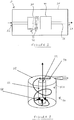
- Figure 1 shows a vacuum cleaner 10 comprising: a body 20 defining an air inlet 22, an air outlet 24, and a passageway 26 extending therebetween; an electrostatic dust filter 30 for removing dust from air as it passes through passageway 26; and an air pump 40 for drawing air into air inlet 22 and through passageway 26 to air outlet 24.
- air inlet 22 and air outlet 24 are shown on opposed sides of body 20 in the schematic illustration, air inlet 22 and air outlet 24 may be arranged to be adjacent one another or preferably in a concentric relationship at the dust entry location (e.g. with air outlet 24 surrounding a wand brush head of the vacuum cleaner).
- Electrostatic dust filter 30 has two main functions: 1) to control the electrostatic charge on dust particles passing through passageway 26 so that the dust particles can be electrostatically filtered out; and 2) sterilisation of the air passing through passageway 26.
- vacuum cleaner 10 may be further configured to control the electrostatic charge on air exiting the passageway 26 via the air outlet 24 (e.g. to allow the vacuum cleaner to exhaust or otherwise emit air of a beneficial and typically negative state of ionization).
- Electrostatic dust filter 30 comprises an electrode arrangement 32 configured to kill microorganisms (e.g. bacteria and bugs) present in air passing through the vacuum cleaner by exposing air to a voltage in excess of a threshold voltage of at least 1000 V and configured to substantially sterilise air passing through the passageway.
- the threshold voltage is at least 10,000 V.
- the facility to control the ionization state of the air/dust particles and sterilise the air can be implemented in a number of ways.
- electrostatic dust filter 30 may comprise an ionising chamber configured to operate with an active input of power and constructed to provide minimum impedance to airflow whilst the chamber is fitted with an electrode arrangement 32 (e.g. two or more plate electrodes) powered so as to maintain an electrical field of adequate length in the airflow direction to ensure capture of a suitable proportion of dust particles (e.g. substantially all particles in the case that the ionising chamber is the only or primary dust filter of the vacuum cleaner). This applies to dust extraction of incoming air and also to beneficial ionization of outgoing air.
- an electrode arrangement 32 e.g. two or more plate electrodes
- electrostatic dust filter may comprise an electrode arrangement 32 in the form of an electrostatic filter screen comprising an electrically conductive body connected to a pulsed capacitor energy store.
- the surface of the filter screen may be coated with a triboelectric material that is at the negative end of the triboelectric series and thus develops a negative charge as the airflow passes over the surface.
- the coating is selected to be sufficiently thin (e.g. 5 nm or less in thickness) so as to allow quantum tunnelling of current through to the electrically conductive body. This results in the airflow being charged positive as it leaves the filter and an accumulation of electrons in the energy store.
- Air pump 40 may comprise any means for generating a vacuum including but not limited to a vacuum impeller, a Tesla turbine and an electrostatic fluid accelerator (EFA).
- electrode arrangement 32 may provides a motive force to drive an electrostatic motor mechanically coupled to the air pump or may even be configured to provide a motive force to directly drive the air pump (see discussion of Tesla turbine embodiment below).
- an active part (e.g. moving blades) of air pump 40 may include an electrically conductive underlayer with a thin (e.g. 5 nm or less in thickness) triboelectric layer, this time at the positive end of the scale and thus configured to develop a positive charge by delivering electrons to the positive charge of the moving air/particles.
- the positive charge is stored on the opposite side of the energy store and provides a balance to the negative store side. This stored charge may be used as part of the cleaning/purifying ionization/filtering process.
- FIG. 2 shows an optional cyclonic electrostatic dust filter stage 50 for use in combination with electrostatic dust filter 30.
- Cyclonic filter stage 50 comprises a cylindrical chamber 52 including an entry port 54 at an upper end thereof and a hollow central cylindrical exit tube 56 defining a plurality of exit holes 58 at a lower end thereof.
- Dust laden air is drawn in via entry port 54 from where it is directed towards the lower exit holes 58 following a circular motion principally against an electrically conductive chamber inner wall 52A of chamber 52 which is electrically connected to one terminal of a DC supply.
- the dust particles are attracted to the electrically conductive inner wall 52A and this together with the centrifugal force causes the dust to separate from the airflow and be retained on chamber inner wall 52A. Meanwhile the air exits chamber 52 via outlet 59 at an upper end of central exit tube 56.
- chamber inner wall 52A Since it is advantageous for chamber inner wall 52A to have a large surface area so as to better attract more dust particles, the surface can be corrugated in the vertical direction providing a localized degree of turbulence and extra surface to retain dust.
- the polarity of inner wall surface can be positive or negative to suit the circumstance of the particular type of dust and conditions that prevail in the local atmosphere.
- Central exit tube 56 is electrically connected to the opposite DC supply connection to that of chamber inner wall 52A. Thus there is an electric field across the space between central exit tube 56 and chamber inner wall 52A. This field acts on the dust particles to attract them to chamber inner wall 52A.
- chamber 52 When chamber 52 is substantially full with dust particles it can be emptied by allowing chamber inner wall 52A to be connected to a ground or earth connection rather than the DC supply terminal. This allows for charge built up in and on the dust particles to be partially discharged and the dust to be free of its attraction to chamber inner wall 52A.
- Chamber 52 may be followed by a second chamber (not shown) of similar function wherein any remnant particles of dust are captured, before the transport air is directed towards an exit to atmosphere point.
- the vacuum cleaner 10 may optionally balance the net charge carried by the airstream so that an overall negative charge state exists on exit from the vacuum cleaner.
- conductive chamber inner wall 52A comprises a conductive substrate coated with a thin coating of insulating material, preferably though not exclusively a ceramic material, chosen to have maximum triboelectric properties and as such readily gives up or accepts electrons as a consequence of friction with the dust particles passing over its surface.
- the coating is very thin (e.g. no greater than 5nm in thickness) to allow quantum tunnelling to take place and allow charge to migrate to the conductive substrate and thus provides a current flow into a suitable storage device such as a capacitor or alternatively directly into a load circuit of some kind.
- the polarity in the cyclonic filter stage 50 can be reversed so that the air leaving chamber 52 has a positive charge state.
- the outgoing air may be passed through a conditioner stage that removes the positive charge and gives the air with a negative charge - thus again improving the overall air quality. It can also be arranged to further trap/remove any remnant dust particles.
- This charge flow is thus an energy extraction system taking electrical energy from the kinetic air flow. The energy can either be accumulated to be used to power the process itself, or be extracted for other purposes (e.g. powering another part of the vacuum cleaner).
- electrostatic cyclonic filter stage 50 examples include a series of vertically orientated electrodes instead of a continuous conductive substrate, each electrode connected to a different phase of control. By sequencing the energisation of the electrodes, a rotating electric field can be established. The rotating field can be used to both drive the flow of air and dust particles and also to sequence the collection of triboelectric generated electron flow.
- Either arrangement can be organized to be conical in form so that velocities of the rotating flows can be optimized.
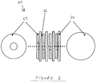
- FIG. 3 shows a Tesla turbine impeller device 60 for use as air pump 40 in vacuum cleaner 10 in accordance with an embodiment of the claimed invention.
- Tesla turbine 60 comprising an arrangement of rotor discs 62 are mounted on a common axis spaced between interposed stator discs 64 with a running clearance 66.
- the resultant electrostatic charge further enhances the drag and hence the pumping effectiveness, whilst at the same time providing for either or both, air quality improvement and or dust particle ionization.
- the dust ionization/charging can then subsequently be used to filter out the dust by collection on suitably charged plates following the turbine stage.
- rotor and stator discs 62, 64 may be coated with a thin (e.g. less than 5 nm in thickness) triboelectric coating to induce friction generated electron flow and collection via quantum tunneling effect to a substrate conductor or conductors.
- stator discs of a Tesla turbine device By suitably arranging electrodes radially on the stator discs of a Tesla turbine device (e.g. based on the principles of known electrostatic motors), it is possible to provide an electrostatic force that spins rotor discs 62 relative to stator discs 64.
- the motor can also perform as the air pump (e.g. impeller) as the air movement is required to be the same as a simple Tesla turbine impeller. That is the motor rotors and stators are the turbine rotors and stators 62, 64.
Description
- The present invention relates to vacuum cleaners and particularly, but not exclusively, vacuum cleaners for domestic use.
- Typically vacuum cleaners in the art operate by creating a pressure difference by means of a rotating fan or impeller powered by an electric motor. The positive pressure is vented to atmosphere through a dispersion system, whilst the negative pressure is directed toward the end of a wand or tube that interfaces with the ground/object to be cleaned. The resulting flow of air through the vacuum cleaner passes through a dust trapping chamber either in the form of a porous bag having a porosity small enough to retain particles, or via a cyclonic chamber that catches the particles by virtue of centrifugal action acting on the swirling particles. The airflow continues from the top of the cyclonic chamber, or via an enclosing chamber in the case of a porous bag, to an exit filter before arriving at atmosphere in the form of a diffuse exhaust.
- Various attempts over the years have been made to improve performance, for example by improving the efficiency of the impeller fan, by increasing the speed of the impeller fan, by carefully engineering the impeller to be a type of spiral form multi-blade turbine, by the use of cyclone technology where the air is directed to swirl so as to create a centrifugal component to the flow and to allow velocity increase by progressive reduction of swirl flow diameter.
- Dust extraction in the present machines is principally a function of vacuum or negative pressure performance. This performance is in turn mostly dependent upon impeller design and efficiency. It is typically the case that impeller efficiency will be below 50%. However some recent turbine type impellers are purported to be as high as 70% efficiency. Total system performance is further reduced by factors such as loss through the wand system, and brush head design with respect to how air flow is constrained from atmosphere to the vacuum entry zone of the head.
- With bag-type filters a small porosity will trap most particles, but too small a porosity results in flow constraints and large pressure drop across the bag. Thus there is a compromise that requires small particles to be let through the filter system. Cyclonic systems capture the primary dust particles by swirling centrifugal force acting on the particles causing them to be thrown against the container wall. Air flow from the container is filtered through a secondary system which again must have porosity to allow air through and so has to have a pathway for particles. Thus neither filtration technique is ideal or close to perfect and in both bag and cyclone systems the exhaust air flow by definition contains particles of dust and/or microbes that are too small for the filter systems to capture.
- Problems are also associated with the ease of emptying dust collectors. Bags must be removed, unsealed and tipped into a waste bin. Often the bag is non-reusable and the whole bag is disposed of when full. In cyclonic system emptying typically has a removable vessel that is simply tipped up to dispose of the contents - at least this is the theory. In practice the vessel is often constructed of or coated with plastic material that becomes statically charged due to the movement and consequent friction of the particles of dust with the vessel inner surfaces. This triboelectric effect causes the particles to stick to the surfaces of the vessel and thus become difficult to empty.
- Finally, the process of moving air at high velocities over insulate surfaces results in charge build up and substantial positive ionisation of the exhaust air. In particular this is an issue with high velocity cyclone type systems where the triboelectric effect is amplified by particle velocity and friction. The electric motor causes magnetically induced positive ionization whilst universal motors are more of an issue with brush sparking adding to the ionization effect and producing a fire hazard. The positive ionization is a known health hazard at worst and at best is believed to contribute to fuzziness of thought and higher propensity to illness.
-
US 2004/035093 discloses a vacuum cleaner in accordance with the precharacterising portion of the independent claims. The present applicant has identified the need for an improved vacuum cleaner that overcomes or at least alleviates problems associated with the prior art. - In accordance with a second aspect of the present invention, there is provided a vacuum cleaner comprising: a body defining an air inlet, an air outlet, and a passageway extending therebetween; a dust filter for removing dust (e.g. for collection in a dust collection chamber) from air as it passes through the passageway; and an air pump for drawing air into the air inlet and through the passageway to the air outlet; wherein the vacuum cleaner further comprises an electrode arrangement operative to provide a motive force to drive an electrostatic motor mechanically coupled to the air pump or to provide a motive force to directly drive the air pump.
- In one embodiment, the air pump comprises a Tesla turbine comprising at least one stator disc in combination with at least one rotor disc and the electrode arrangement is provided on the at least one stator disc to cause rotation of the corresponding rotor disc.
- In one embodiment, the passageway or a component located in the passageway includes an airflow contact surface comprising a triboelectric coating provided on an electrically conductive underlayer configured to supply a voltage to the electrode arrangement.
- In one embodiment, the air pump comprises an active element (e.g. blade of a fan or plate of a Tesla turbine) including an airflow contact surface comprising a triboelectric coating provided on an electrically conductive layer configured to supply a voltage to the electrode arrangement.
- In one embodiment, the electrostatic dust filter includes a cyclonic filter stage including a cyclonic airflow contact surface comprising a triboelectric coating provided on an electrically conductive underlayer configured to supply a voltage to the electrode arrangement.
- In one embodiment, the vacuum cleaner is configured to generate an ionised airflow through the air outlet (e.g. negatively ionised airflow).
- Embodiments of the present invention will now be described by way of example with reference to the accompanying drawings in which:
-
Figure 1 is a schematic illustration of a vacuum cleaner; -
Figure 2 is a schematic view of an electrostatic cyclone filter for use in the vacuum cleaner ofFigure 1 ; and -
Figure 3 is a schematic view of an air pump for use in the vacuum cleaner ofFigure 1 . -
Figure 1 shows avacuum cleaner 10 comprising: abody 20 defining anair inlet 22, anair outlet 24, and apassageway 26 extending therebetween; anelectrostatic dust filter 30 for removing dust from air as it passes throughpassageway 26; and anair pump 40 for drawing air intoair inlet 22 and throughpassageway 26 toair outlet 24. Although theair inlet 22 andair outlet 24 are shown on opposed sides ofbody 20 in the schematic illustration,air inlet 22 andair outlet 24 may be arranged to be adjacent one another or preferably in a concentric relationship at the dust entry location (e.g. withair outlet 24 surrounding a wand brush head of the vacuum cleaner). -
Electrostatic dust filter 30 has two main functions: 1) to control the electrostatic charge on dust particles passing throughpassageway 26 so that the dust particles can be electrostatically filtered out; and 2) sterilisation of the air passing throughpassageway 26. Optionally, vacuum cleaner 10 (either by means ofelectrostatic dust filter 30 itself by means of a further charge control device located downstream of electrostatic dust filter 30) may be further configured to control the electrostatic charge on air exiting thepassageway 26 via the air outlet 24 (e.g. to allow the vacuum cleaner to exhaust or otherwise emit air of a beneficial and typically negative state of ionization). -
Electrostatic dust filter 30 comprises anelectrode arrangement 32 configured to kill microorganisms (e.g. bacteria and bugs) present in air passing through the vacuum cleaner by exposing air to a voltage in excess of a threshold voltage of at least 1000 V and configured to substantially sterilise air passing through the passageway. In one example, the threshold voltage is at least 10,000 V. - The facility to control the ionization state of the air/dust particles and sterilise the air can be implemented in a number of ways.
- In a first example,
electrostatic dust filter 30 may comprise an ionising chamber configured to operate with an active input of power and constructed to provide minimum impedance to airflow whilst the chamber is fitted with an electrode arrangement 32 (e.g. two or more plate electrodes) powered so as to maintain an electrical field of adequate length in the airflow direction to ensure capture of a suitable proportion of dust particles (e.g. substantially all particles in the case that the ionising chamber is the only or primary dust filter of the vacuum cleaner). This applies to dust extraction of incoming air and also to beneficial ionization of outgoing air. - In another example, electrostatic dust filter may comprise an
electrode arrangement 32 in the form of an electrostatic filter screen comprising an electrically conductive body connected to a pulsed capacitor energy store. The surface of the filter screen may be coated with a triboelectric material that is at the negative end of the triboelectric series and thus develops a negative charge as the airflow passes over the surface. The coating is selected to be sufficiently thin (e.g. 5 nm or less in thickness) so as to allow quantum tunnelling of current through to the electrically conductive body. This results in the airflow being charged positive as it leaves the filter and an accumulation of electrons in the energy store. -
Air pump 40 may comprise any means for generating a vacuum including but not limited to a vacuum impeller, a Tesla turbine and an electrostatic fluid accelerator (EFA). In one example,electrode arrangement 32 may provides a motive force to drive an electrostatic motor mechanically coupled to the air pump or may even be configured to provide a motive force to directly drive the air pump (see discussion of Tesla turbine embodiment below). - In the case of a mechanical air pump, an active part (e.g. moving blades) of
air pump 40 may include an electrically conductive underlayer with a thin (e.g. 5 nm or less in thickness) triboelectric layer, this time at the positive end of the scale and thus configured to develop a positive charge by delivering electrons to the positive charge of the moving air/particles. The positive charge is stored on the opposite side of the energy store and provides a balance to the negative store side. This stored charge may be used as part of the cleaning/purifying ionization/filtering process. -
Figure 2 shows an optional cyclonic electrostaticdust filter stage 50 for use in combination withelectrostatic dust filter 30.Cyclonic filter stage 50 comprises acylindrical chamber 52 including anentry port 54 at an upper end thereof and a hollow centralcylindrical exit tube 56 defining a plurality ofexit holes 58 at a lower end thereof. - Dust laden air is drawn in via
entry port 54 from where it is directed towards thelower exit holes 58 following a circular motion principally against an electrically conductive chamber inner wall 52A ofchamber 52 which is electrically connected to one terminal of a DC supply. The dust particles are attracted to the electrically conductive inner wall 52A and this together with the centrifugal force causes the dust to separate from the airflow and be retained on chamber inner wall 52A. Meanwhile the air exits chamber 52 viaoutlet 59 at an upper end ofcentral exit tube 56. - Since it is advantageous for chamber inner wall 52A to have a large surface area so as to better attract more dust particles, the surface can be corrugated in the vertical direction providing a localized degree of turbulence and extra surface to retain dust.
- The polarity of inner wall surface can be positive or negative to suit the circumstance of the particular type of dust and conditions that prevail in the local atmosphere.
-
Central exit tube 56 is electrically connected to the opposite DC supply connection to that of chamber inner wall 52A. Thus there is an electric field across the space betweencentral exit tube 56 and chamber inner wall 52A. This field acts on the dust particles to attract them to chamber inner wall 52A. - When
chamber 52 is substantially full with dust particles it can be emptied by allowing chamber inner wall 52A to be connected to a ground or earth connection rather than the DC supply terminal. This allows for charge built up in and on the dust particles to be partially discharged and the dust to be free of its attraction to chamber inner wall 52A. -
Chamber 52 may be followed by a second chamber (not shown) of similar function wherein any remnant particles of dust are captured, before the transport air is directed towards an exit to atmosphere point. - On its way to the exit to atmosphere, the
vacuum cleaner 10 may optionally balance the net charge carried by the airstream so that an overall negative charge state exists on exit from the vacuum cleaner. - In one example, conductive chamber inner wall 52A comprises a conductive substrate coated with a thin coating of insulating material, preferably though not exclusively a ceramic material, chosen to have maximum triboelectric properties and as such readily gives up or accepts electrons as a consequence of friction with the dust particles passing over its surface. The coating is very thin (e.g. no greater than 5nm in thickness) to allow quantum tunnelling to take place and allow charge to migrate to the conductive substrate and thus provides a current flow into a suitable storage device such as a capacitor or alternatively directly into a load circuit of some kind.
- By way of example, if
cyclonic filter stage 50 operates with a negative voltage at the substrate (with respect to exit tube 56), dust particles will be in frictional contact with chamber inner wall 52A which has a positive triboelectric characteristic - i.e. readily gives up electrons. As the dust particles extract electrons from the surface of the coating on the chamber inner wall 52A they become negatively charged and the surface material gains a positive charge. As this positive charge accumulates, quantum tunneling migrates electrons from the conductive substrate to the surface of the coating to neutralise the charge and allow the cycle to progress. Thus an electron flow is established. The dust meanwhile is first attracted to surface of the coating and subsequently, after the electron neutralization, is allowed to fall and accumulate at the bottom ofchamber 52. In this example the air is also negatively charged and so has an improved quality state prior to it's exit at an exhaust point. - As will be apparent to the skilled reader, the polarity in the
cyclonic filter stage 50 can be reversed so that theair leaving chamber 52 has a positive charge state. In this case, the outgoing air may be passed through a conditioner stage that removes the positive charge and gives the air with a negative charge - thus again improving the overall air quality. It can also be arranged to further trap/remove any remnant dust particles. However, in this latter case the balance of the positive charge first acquired by the air and the subsequent negative charge result in a closed circuit of charge flow between the two sections. This charge flow is thus an energy extraction system taking electrical energy from the kinetic air flow. The energy can either be accumulated to be used to power the process itself, or be extracted for other purposes (e.g. powering another part of the vacuum cleaner). - Further examples of electrostatic
cyclonic filter stage 50 include a series of vertically orientated electrodes instead of a continuous conductive substrate, each electrode connected to a different phase of control. By sequencing the energisation of the electrodes, a rotating electric field can be established. The rotating field can be used to both drive the flow of air and dust particles and also to sequence the collection of triboelectric generated electron flow. - Either arrangement can be organized to be conical in form so that velocities of the rotating flows can be optimized.
-
Figure 3 shows a Teslaturbine impeller device 60 for use asair pump 40 in vacuum cleaner 10 in accordance with an embodiment of the claimed invention. -
Tesla turbine 60 comprising an arrangement ofrotor discs 62 are mounted on a common axis spaced between interposedstator discs 64 with a runningclearance 66. - As in a conventional Tesla Turbine, air is drawn in at the axis, accelerated and expelled at the periphery where a containing chamber catches and directs the output. This process provides for very quiet operation as there are no impeller blades.
- By making rotor and
stator discs - Additionally rotor and
stator discs - By suitably arranging electrodes radially on the stator discs of a Tesla turbine device (e.g. based on the principles of known electrostatic motors), it is possible to provide an electrostatic force that spins
rotor discs 62 relative tostator discs 64. In this way the motor can also perform as the air pump (e.g. impeller) as the air movement is required to be the same as a simple Tesla turbine impeller. That is the motor rotors and stators are the turbine rotors andstators
Claims (6)
- A vacuum cleaner (10) comprising:a body (20) defining an air inlet (22), an air outlet (24), and a passageway (26) extending therebetween;a dust filter (30) for removing dust from air as it passes through the passageway (26); andan air pump (40) for drawing air into the air inlet (22) and through the passageway (26) to the air outlet (24);characterised in that the vacuum cleaner (10) further comprises an electrode arrangement (32) operative to provide a motive force to drive an electrostatic motor mechanically coupled to the air pump (40) or to provide a motive force to directly drive the air pump (40).
- A vacuum cleaner (10) according to claim 1, wherein the air pump (40) comprises a Tesla turbine (60) comprising at least one stator disc (64) in combination with at least one rotor disc (62) and the electrode arrangement (32) is provided on the at least one stator disc (64) to cause rotation of the corresponding rotor disc (62).
- A vacuum cleaner (10) according to claim 1 or claim 2, wherein the passageway (26) or a component located in the passageway (26) includes an airflow contact surface comprising a triboelectric coating provided on an electrically conductive underlayer configured to supply a voltage to the electrode arrangement (32).
- A vacuum cleaner (10) according to any preceding claim, wherein the air pump (40) comprises an active element including an airflow contact surface comprising a triboelectric coating provided on an electrically conductive layer configured to supply a voltage to the electrode arrangement (32).
- A vacuum cleaner (10) according to any preceding claim, wherein the dust filter (30) is an electrostatic dust filter comprising a cyclonic filter stage (50) including a cyclonic airflow contact surface (52A)comprising a triboelectric coating provided on an electrically conductive underlayer configured to supply a voltage to the electrode arrangement (32).
- A vacuum cleaner (10) according to any preceding claim, wherein the vacuum cleaner (10) is configured to generate an ionised airflow through the air outlet.
Applications Claiming Priority (2)
| Application Number | Priority Date | Filing Date | Title |
|---|---|---|---|
| GBGB1311451.7A GB201311451D0 (en) | 2013-06-27 | 2013-06-27 | Vacuum Cleaner |
| PCT/GB2014/051927 WO2014207449A2 (en) | 2013-06-27 | 2014-06-24 | Vacuum cleaner |
Publications (2)
| Publication Number | Publication Date |
|---|---|
| EP3013204A2 EP3013204A2 (en) | 2016-05-04 |
| EP3013204B1 true EP3013204B1 (en) | 2018-10-24 |
Family
ID=48999054
Family Applications (1)
| Application Number | Title | Priority Date | Filing Date |
|---|---|---|---|
| EP14744890.6A Not-in-force EP3013204B1 (en) | 2013-06-27 | 2014-06-24 | Vacuum cleaner with electrostatic filter |
Country Status (8)
| Country | Link |
|---|---|
| US (1) | US10231586B2 (en) |
| EP (1) | EP3013204B1 (en) |
| JP (1) | JP6465875B2 (en) |
| CN (1) | CN105358029A (en) |
| BR (1) | BR112015032551A2 (en) |
| GB (1) | GB201311451D0 (en) |
| RU (1) | RU2667238C2 (en) |
| WO (1) | WO2014207449A2 (en) |
Families Citing this family (1)
| Publication number | Priority date | Publication date | Assignee | Title |
|---|---|---|---|---|
| US11957295B2 (en) * | 2021-12-02 | 2024-04-16 | Richard HILLERY | Pneumatic vacuum cleaner |
Family Cites Families (25)
| Publication number | Priority date | Publication date | Assignee | Title |
|---|---|---|---|---|
| GB1501927A (en) | 1976-08-26 | 1978-02-22 | Bates W | Vacuum cleaner |
| JPH0182705U (en) * | 1987-11-20 | 1989-06-01 | ||
| US5150499A (en) * | 1990-11-16 | 1992-09-29 | Shop Vac Corporation | Static electric discharge for dust collector |
| US5400465A (en) * | 1994-03-30 | 1995-03-28 | Home Care Industries, Inc. | Vacuum cleaner with charge generator and bag therefor |
| JPH09182705A (en) * | 1995-12-28 | 1997-07-15 | Nec Home Electron Ltd | Vacuum cleaner |
| IT1284447B1 (en) | 1996-06-27 | 1998-05-21 | Candy Spa | ELECTRO-CYCLONE VACUUM CLEANER AND RELATED ELECTRO-CYCLONE FILTER CARTRIDGE |
| DE69716427T2 (en) * | 1997-07-28 | 2003-03-06 | Candy Spa | Vacuum cleaner with a directly generated electrostatic effect |
| JPH11353540A (en) * | 1998-06-08 | 1999-12-24 | Fuji Denki Reiki Co Ltd | Automatic vending machine |
| US20040035093A1 (en) | 1999-01-08 | 2004-02-26 | Conrad Wayne Ernest | Vacuum cleaner |
| JP2001017361A (en) * | 1999-07-07 | 2001-01-23 | Matsushita Electric Ind Co Ltd | Vacuum cleaner |
| JP2001037687A (en) * | 1999-08-02 | 2001-02-13 | Matsushita Electric Ind Co Ltd | Vacuum cleaner |
| US6198195B1 (en) * | 1999-10-12 | 2001-03-06 | Oreck Holdings, Llc | High efficiency motor for low velocity, high volume fan and other applications |
| CA2339514A1 (en) * | 2001-03-06 | 2002-09-06 | Wayne Ernest Conrad | Vacuum cleaner utilizing electrostatic filtration and electrostatic precipitator for use therein |
| CN1264466C (en) * | 2001-11-19 | 2006-07-19 | 乐金电子(天津)电器有限公司 | Cyclone dust-collector for vacuum cleaner |
| AU2002258715A1 (en) * | 2002-04-04 | 2003-10-20 | Illusion Technologies, Llc | Miniature/micro scale power generation system |
| JP2004013582A (en) * | 2002-06-07 | 2004-01-15 | Nissan Motor Co Ltd | Electrostatically charged management tag |
| TW587768U (en) * | 2003-01-30 | 2004-05-11 | Molex Inc | Heat-dissipating device |
| KR20060026574A (en) | 2004-09-21 | 2006-03-24 | 삼성광주전자 주식회사 | Cyclone dust collecting appartus |
| US8292979B2 (en) | 2006-03-10 | 2012-10-23 | G.B.D. Corp | Vacuum cleaner with a removable screen |
| JP2007244526A (en) * | 2006-03-14 | 2007-09-27 | Sharp Corp | Electric appliance |
| CN100420416C (en) * | 2006-04-06 | 2008-09-24 | 苏州金莱克家用电器有限公司 | Separator with multi-air intake and dust cup device thereof |
| KR101610186B1 (en) * | 2009-06-17 | 2016-04-07 | 삼성전자주식회사 | Dust collector of vacuum cleaner having a function of removing dust detached from filter |
| GB2472097B (en) | 2009-07-24 | 2013-04-17 | Dyson Technology Ltd | Separating apparatus with electrostatic filter |
| GB2472095A (en) * | 2009-07-24 | 2011-01-26 | Dyson Technology Ltd | Vacuum cleaner with cyclone and electrostatic filter arrangement |
| DE102009038230A1 (en) * | 2009-08-20 | 2011-02-24 | Heinrich Essers Gmbh & Co. Kg | Solid filter, especially for a vacuum cleaner, and vacuum cleaner with a solid filter |
-
2013
- 2013-06-27 GB GBGB1311451.7A patent/GB201311451D0/en not_active Ceased
-
2014
- 2014-06-24 BR BR112015032551A patent/BR112015032551A2/en not_active IP Right Cessation
- 2014-06-24 RU RU2015152548A patent/RU2667238C2/en active
- 2014-06-24 CN CN201480037122.6A patent/CN105358029A/en active Pending
- 2014-06-24 JP JP2016522861A patent/JP6465875B2/en active Active
- 2014-06-24 US US14/899,517 patent/US10231586B2/en not_active Expired - Fee Related
- 2014-06-24 EP EP14744890.6A patent/EP3013204B1/en not_active Not-in-force
- 2014-06-24 WO PCT/GB2014/051927 patent/WO2014207449A2/en active Application Filing
Non-Patent Citations (1)
| Title |
|---|
| None * |
Also Published As
| Publication number | Publication date |
|---|---|
| EP3013204A2 (en) | 2016-05-04 |
| US20160150930A1 (en) | 2016-06-02 |
| GB201311451D0 (en) | 2013-08-14 |
| WO2014207449A3 (en) | 2015-04-09 |
| RU2015152548A3 (en) | 2018-05-23 |
| RU2015152548A (en) | 2017-08-01 |
| RU2667238C2 (en) | 2018-09-17 |
| WO2014207449A2 (en) | 2014-12-31 |
| JP2016527936A (en) | 2016-09-15 |
| BR112015032551A2 (en) | 2017-07-25 |
| JP6465875B2 (en) | 2019-02-06 |
| US10231586B2 (en) | 2019-03-19 |
| CN105358029A (en) | 2016-02-24 |
Similar Documents
| Publication | Publication Date | Title |
|---|---|---|
| EP2456342B1 (en) | An electrostatic filter | |
| JP5421204B2 (en) | Separation device | |
| EP2279685B1 (en) | A cyclonic separating apparatus with electrostatic filter | |
| US4976749A (en) | Air filter and particle removal system | |
| US20100236012A1 (en) | Cleaning and/or filtering apparatus | |
| US20020134238A1 (en) | Vacuum cleaner utilizing electrostatic filtration and electrostatic precipitator for use therein | |
| JP4889386B2 (en) | Vacuum cleaner | |
| CN101111318A (en) | Electric dust collector | |
| CN109297062A (en) | Centrifugal Electrostatic Combined type lampblack purifier | |
| JP2022508869A (en) | Air dust removal system and method | |
| EP3013204B1 (en) | Vacuum cleaner with electrostatic filter | |
| JP4971472B2 (en) | Electric vacuum cleaner | |
| KR100980341B1 (en) | Electric Multi Cyclone Scrubber | |
| KR102094907B1 (en) | Cycline filter unit | |
| KR102123851B1 (en) | Cyclone module capable of removing fine dust and ultrafine dust | |
| JP2006180937A (en) | Vacuum cleaner | |
| JP2007159654A (en) | Vacuum cleaner | |
| JP5486617B2 (en) | Electric vacuum cleaner | |
| JP2000046358A (en) | Electrostatic air cleaner | |
| KR20180131773A (en) | Air cleaner using electric field | |
| KR20180131774A (en) | Air cleaner using electric field | |
| KR19980074238A (en) | Electrostatic Filtration Dust Collecting Method by Corona Discharge and Its Apparatus | |
| WO2022149298A1 (en) | Air purifier for removing viruses | |
| KR970003860B1 (en) | Electric dust collector | |
| JP2015182000A (en) | Air purifying device |
Legal Events
| Date | Code | Title | Description |
|---|---|---|---|
| PUAI | Public reference made under article 153(3) epc to a published international application that has entered the european phase |
Free format text: ORIGINAL CODE: 0009012 |
|
| 17P | Request for examination filed |
Effective date: 20160118 |
|
| AK | Designated contracting states |
Kind code of ref document: A2 Designated state(s): AL AT BE BG CH CY CZ DE DK EE ES FI FR GB GR HR HU IE IS IT LI LT LU LV MC MK MT NL NO PL PT RO RS SE SI SK SM TR |
|
| AX | Request for extension of the european patent |
Extension state: BA ME |
|
| DAX | Request for extension of the european patent (deleted) | ||
| STAA | Information on the status of an ep patent application or granted ep patent |
Free format text: STATUS: EXAMINATION IS IN PROGRESS |
|
| 17Q | First examination report despatched |
Effective date: 20170518 |
|
| GRAP | Despatch of communication of intention to grant a patent |
Free format text: ORIGINAL CODE: EPIDOSNIGR1 |
|
| STAA | Information on the status of an ep patent application or granted ep patent |
Free format text: STATUS: GRANT OF PATENT IS INTENDED |
|
| INTG | Intention to grant announced |
Effective date: 20180509 |
|
| GRAS | Grant fee paid |
Free format text: ORIGINAL CODE: EPIDOSNIGR3 |
|
| GRAA | (expected) grant |
Free format text: ORIGINAL CODE: 0009210 |
|
| STAA | Information on the status of an ep patent application or granted ep patent |
Free format text: STATUS: THE PATENT HAS BEEN GRANTED |
|
| AK | Designated contracting states |
Kind code of ref document: B1 Designated state(s): AL AT BE BG CH CY CZ DE DK EE ES FI FR GB GR HR HU IE IS IT LI LT LU LV MC MK MT NL NO PL PT RO RS SE SI SK SM TR |
|
| REG | Reference to a national code |
Ref country code: CH Ref legal event code: EP |
|
| REG | Reference to a national code |
Ref country code: IE Ref legal event code: FG4D |
|
| REG | Reference to a national code |
Ref country code: AT Ref legal event code: REF Ref document number: 1055678 Country of ref document: AT Kind code of ref document: T Effective date: 20181115 |
|
| REG | Reference to a national code |
Ref country code: DE Ref legal event code: R096 Ref document number: 602014034652 Country of ref document: DE |
|
| REG | Reference to a national code |
Ref country code: NL Ref legal event code: MP Effective date: 20181024 |
|
| REG | Reference to a national code |
Ref country code: LT Ref legal event code: MG4D |
|
| REG | Reference to a national code |
Ref country code: AT Ref legal event code: MK05 Ref document number: 1055678 Country of ref document: AT Kind code of ref document: T Effective date: 20181024 |
|
| PG25 | Lapsed in a contracting state [announced via postgrant information from national office to epo] |
Ref country code: NL Free format text: LAPSE BECAUSE OF FAILURE TO SUBMIT A TRANSLATION OF THE DESCRIPTION OR TO PAY THE FEE WITHIN THE PRESCRIBED TIME-LIMIT Effective date: 20181024 |
|
| PG25 | Lapsed in a contracting state [announced via postgrant information from national office to epo] |
Ref country code: LV Free format text: LAPSE BECAUSE OF FAILURE TO SUBMIT A TRANSLATION OF THE DESCRIPTION OR TO PAY THE FEE WITHIN THE PRESCRIBED TIME-LIMIT Effective date: 20181024 Ref country code: AT Free format text: LAPSE BECAUSE OF FAILURE TO SUBMIT A TRANSLATION OF THE DESCRIPTION OR TO PAY THE FEE WITHIN THE PRESCRIBED TIME-LIMIT Effective date: 20181024 Ref country code: BG Free format text: LAPSE BECAUSE OF FAILURE TO SUBMIT A TRANSLATION OF THE DESCRIPTION OR TO PAY THE FEE WITHIN THE PRESCRIBED TIME-LIMIT Effective date: 20190124 Ref country code: LT Free format text: LAPSE BECAUSE OF FAILURE TO SUBMIT A TRANSLATION OF THE DESCRIPTION OR TO PAY THE FEE WITHIN THE PRESCRIBED TIME-LIMIT Effective date: 20181024 Ref country code: FI Free format text: LAPSE BECAUSE OF FAILURE TO SUBMIT A TRANSLATION OF THE DESCRIPTION OR TO PAY THE FEE WITHIN THE PRESCRIBED TIME-LIMIT Effective date: 20181024 Ref country code: IS Free format text: LAPSE BECAUSE OF FAILURE TO SUBMIT A TRANSLATION OF THE DESCRIPTION OR TO PAY THE FEE WITHIN THE PRESCRIBED TIME-LIMIT Effective date: 20190224 Ref country code: NO Free format text: LAPSE BECAUSE OF FAILURE TO SUBMIT A TRANSLATION OF THE DESCRIPTION OR TO PAY THE FEE WITHIN THE PRESCRIBED TIME-LIMIT Effective date: 20190124 Ref country code: HR Free format text: LAPSE BECAUSE OF FAILURE TO SUBMIT A TRANSLATION OF THE DESCRIPTION OR TO PAY THE FEE WITHIN THE PRESCRIBED TIME-LIMIT Effective date: 20181024 Ref country code: ES Free format text: LAPSE BECAUSE OF FAILURE TO SUBMIT A TRANSLATION OF THE DESCRIPTION OR TO PAY THE FEE WITHIN THE PRESCRIBED TIME-LIMIT Effective date: 20181024 Ref country code: PL Free format text: LAPSE BECAUSE OF FAILURE TO SUBMIT A TRANSLATION OF THE DESCRIPTION OR TO PAY THE FEE WITHIN THE PRESCRIBED TIME-LIMIT Effective date: 20181024 |
|
| PG25 | Lapsed in a contracting state [announced via postgrant information from national office to epo] |
Ref country code: SE Free format text: LAPSE BECAUSE OF FAILURE TO SUBMIT A TRANSLATION OF THE DESCRIPTION OR TO PAY THE FEE WITHIN THE PRESCRIBED TIME-LIMIT Effective date: 20181024 Ref country code: GR Free format text: LAPSE BECAUSE OF FAILURE TO SUBMIT A TRANSLATION OF THE DESCRIPTION OR TO PAY THE FEE WITHIN THE PRESCRIBED TIME-LIMIT Effective date: 20190125 Ref country code: PT Free format text: LAPSE BECAUSE OF FAILURE TO SUBMIT A TRANSLATION OF THE DESCRIPTION OR TO PAY THE FEE WITHIN THE PRESCRIBED TIME-LIMIT Effective date: 20190224 Ref country code: AL Free format text: LAPSE BECAUSE OF FAILURE TO SUBMIT A TRANSLATION OF THE DESCRIPTION OR TO PAY THE FEE WITHIN THE PRESCRIBED TIME-LIMIT Effective date: 20181024 Ref country code: RS Free format text: LAPSE BECAUSE OF FAILURE TO SUBMIT A TRANSLATION OF THE DESCRIPTION OR TO PAY THE FEE WITHIN THE PRESCRIBED TIME-LIMIT Effective date: 20181024 |
|
| REG | Reference to a national code |
Ref country code: DE Ref legal event code: R097 Ref document number: 602014034652 Country of ref document: DE |
|
| PG25 | Lapsed in a contracting state [announced via postgrant information from national office to epo] |
Ref country code: CZ Free format text: LAPSE BECAUSE OF FAILURE TO SUBMIT A TRANSLATION OF THE DESCRIPTION OR TO PAY THE FEE WITHIN THE PRESCRIBED TIME-LIMIT Effective date: 20181024 Ref country code: DK Free format text: LAPSE BECAUSE OF FAILURE TO SUBMIT A TRANSLATION OF THE DESCRIPTION OR TO PAY THE FEE WITHIN THE PRESCRIBED TIME-LIMIT Effective date: 20181024 Ref country code: IT Free format text: LAPSE BECAUSE OF FAILURE TO SUBMIT A TRANSLATION OF THE DESCRIPTION OR TO PAY THE FEE WITHIN THE PRESCRIBED TIME-LIMIT Effective date: 20181024 |
|
| PG25 | Lapsed in a contracting state [announced via postgrant information from national office to epo] |
Ref country code: SK Free format text: LAPSE BECAUSE OF FAILURE TO SUBMIT A TRANSLATION OF THE DESCRIPTION OR TO PAY THE FEE WITHIN THE PRESCRIBED TIME-LIMIT Effective date: 20181024 Ref country code: RO Free format text: LAPSE BECAUSE OF FAILURE TO SUBMIT A TRANSLATION OF THE DESCRIPTION OR TO PAY THE FEE WITHIN THE PRESCRIBED TIME-LIMIT Effective date: 20181024 Ref country code: SM Free format text: LAPSE BECAUSE OF FAILURE TO SUBMIT A TRANSLATION OF THE DESCRIPTION OR TO PAY THE FEE WITHIN THE PRESCRIBED TIME-LIMIT Effective date: 20181024 Ref country code: EE Free format text: LAPSE BECAUSE OF FAILURE TO SUBMIT A TRANSLATION OF THE DESCRIPTION OR TO PAY THE FEE WITHIN THE PRESCRIBED TIME-LIMIT Effective date: 20181024 |
|
| PLBE | No opposition filed within time limit |
Free format text: ORIGINAL CODE: 0009261 |
|
| STAA | Information on the status of an ep patent application or granted ep patent |
Free format text: STATUS: NO OPPOSITION FILED WITHIN TIME LIMIT |
|
| 26N | No opposition filed |
Effective date: 20190725 |
|
| PG25 | Lapsed in a contracting state [announced via postgrant information from national office to epo] |
Ref country code: SI Free format text: LAPSE BECAUSE OF FAILURE TO SUBMIT A TRANSLATION OF THE DESCRIPTION OR TO PAY THE FEE WITHIN THE PRESCRIBED TIME-LIMIT Effective date: 20181024 |
|
| REG | Reference to a national code |
Ref country code: DE Ref legal event code: R119 Ref document number: 602014034652 Country of ref document: DE |
|
| PG25 | Lapsed in a contracting state [announced via postgrant information from national office to epo] |
Ref country code: MC Free format text: LAPSE BECAUSE OF FAILURE TO SUBMIT A TRANSLATION OF THE DESCRIPTION OR TO PAY THE FEE WITHIN THE PRESCRIBED TIME-LIMIT Effective date: 20181024 |
|
| REG | Reference to a national code |
Ref country code: CH Ref legal event code: PL |
|
| GBPC | Gb: european patent ceased through non-payment of renewal fee |
Effective date: 20190624 |
|
| REG | Reference to a national code |
Ref country code: BE Ref legal event code: MM Effective date: 20190630 |
|
| PG25 | Lapsed in a contracting state [announced via postgrant information from national office to epo] |
Ref country code: TR Free format text: LAPSE BECAUSE OF FAILURE TO SUBMIT A TRANSLATION OF THE DESCRIPTION OR TO PAY THE FEE WITHIN THE PRESCRIBED TIME-LIMIT Effective date: 20181024 |
|
| PG25 | Lapsed in a contracting state [announced via postgrant information from national office to epo] |
Ref country code: GB Free format text: LAPSE BECAUSE OF NON-PAYMENT OF DUE FEES Effective date: 20190624 Ref country code: IE Free format text: LAPSE BECAUSE OF NON-PAYMENT OF DUE FEES Effective date: 20190624 Ref country code: DE Free format text: LAPSE BECAUSE OF NON-PAYMENT OF DUE FEES Effective date: 20200101 |
|
| PG25 | Lapsed in a contracting state [announced via postgrant information from national office to epo] |
Ref country code: LI Free format text: LAPSE BECAUSE OF NON-PAYMENT OF DUE FEES Effective date: 20190630 Ref country code: BE Free format text: LAPSE BECAUSE OF NON-PAYMENT OF DUE FEES Effective date: 20190630 Ref country code: CH Free format text: LAPSE BECAUSE OF NON-PAYMENT OF DUE FEES Effective date: 20190630 Ref country code: LU Free format text: LAPSE BECAUSE OF NON-PAYMENT OF DUE FEES Effective date: 20190624 |
|
| PG25 | Lapsed in a contracting state [announced via postgrant information from national office to epo] |
Ref country code: FR Free format text: LAPSE BECAUSE OF NON-PAYMENT OF DUE FEES Effective date: 20190630 |
|
| PG25 | Lapsed in a contracting state [announced via postgrant information from national office to epo] |
Ref country code: CY Free format text: LAPSE BECAUSE OF FAILURE TO SUBMIT A TRANSLATION OF THE DESCRIPTION OR TO PAY THE FEE WITHIN THE PRESCRIBED TIME-LIMIT Effective date: 20181024 |
|
| PG25 | Lapsed in a contracting state [announced via postgrant information from national office to epo] |
Ref country code: MT Free format text: LAPSE BECAUSE OF FAILURE TO SUBMIT A TRANSLATION OF THE DESCRIPTION OR TO PAY THE FEE WITHIN THE PRESCRIBED TIME-LIMIT Effective date: 20181024 Ref country code: HU Free format text: LAPSE BECAUSE OF FAILURE TO SUBMIT A TRANSLATION OF THE DESCRIPTION OR TO PAY THE FEE WITHIN THE PRESCRIBED TIME-LIMIT; INVALID AB INITIO Effective date: 20140624 |
|
| PG25 | Lapsed in a contracting state [announced via postgrant information from national office to epo] |
Ref country code: MK Free format text: LAPSE BECAUSE OF FAILURE TO SUBMIT A TRANSLATION OF THE DESCRIPTION OR TO PAY THE FEE WITHIN THE PRESCRIBED TIME-LIMIT Effective date: 20181024 |