EP3012673B1 - Optical fiber fusion splicer and optical fiber fusion splicing apparatus provided with same - Google Patents
Optical fiber fusion splicer and optical fiber fusion splicing apparatus provided with same Download PDFInfo
- Publication number
- EP3012673B1 EP3012673B1 EP15156192.5A EP15156192A EP3012673B1 EP 3012673 B1 EP3012673 B1 EP 3012673B1 EP 15156192 A EP15156192 A EP 15156192A EP 3012673 B1 EP3012673 B1 EP 3012673B1
- Authority
- EP
- European Patent Office
- Prior art keywords
- pair
- elastic members
- optical fibers
- fixed base
- optical fiber
- Prior art date
- Legal status (The legal status is an assumption and is not a legal conclusion. Google has not performed a legal analysis and makes no representation as to the accuracy of the status listed.)
- Active
Links
Images


Classifications
-
- G—PHYSICS
- G02—OPTICS
- G02B—OPTICAL ELEMENTS, SYSTEMS OR APPARATUS
- G02B6/00—Light guides; Structural details of arrangements comprising light guides and other optical elements, e.g. couplings
- G02B6/24—Coupling light guides
- G02B6/255—Splicing of light guides, e.g. by fusion or bonding
- G02B6/2553—Splicing machines, e.g. optical fibre fusion splicer
-
- G—PHYSICS
- G02—OPTICS
- G02B—OPTICAL ELEMENTS, SYSTEMS OR APPARATUS
- G02B6/00—Light guides; Structural details of arrangements comprising light guides and other optical elements, e.g. couplings
- G02B6/24—Coupling light guides
- G02B6/255—Splicing of light guides, e.g. by fusion or bonding
- G02B6/2555—Alignment or adjustment devices for aligning prior to splicing
- G02B6/2557—Alignment or adjustment devices for aligning prior to splicing using deformable flexure members, flexible hinges or pivotal arms
-
- G—PHYSICS
- G02—OPTICS
- G02B—OPTICAL ELEMENTS, SYSTEMS OR APPARATUS
- G02B6/00—Light guides; Structural details of arrangements comprising light guides and other optical elements, e.g. couplings
- G02B6/24—Coupling light guides
- G02B6/255—Splicing of light guides, e.g. by fusion or bonding
- G02B6/2551—Splicing of light guides, e.g. by fusion or bonding using thermal methods, e.g. fusion welding by arc discharge, laser beam, plasma torch
Definitions
- the present invention relates to an optical fiber fusion splicer and an optical fiber fusion splicing apparatus which is provided with the optical fiber fusion splicer.
- the fusion splice is performed in the following procedure by using an optical fiber fusion splicing apparatus.
- an optical fiber fusion splicer which is used in the process (5) described above, for example, a device (a single-core machine) for fusion-splicing a pair of single-core optical fibers by discharge heating between a pair of electrode rods, or a device (a multi-core machine) for fusion-splicing end portions of a pair of multi-core optical fibers (a tape fiber) together by discharge heating between a pair of electrode rods is provided.
- an optical fiber fusion splicer which is used for a single-core optical fiber
- an optical fiber fusion splicer having a function and a configuration as shown in FIG. 8 and described below is widely used.
- a fusion splicer 101 which is provided with an elastic alignment mechanism having an elastically deformable elastic member, as shown in FIGS. 9 and 10 , is proposed.
- two plate-shaped elastic members 103A are disposed so as to extend obliquely upward from the right side of a fixed base 104 in FIG. 9 , and the tips thereof are connected to a V-grooved stand 102A with a V-groove 121 provided therein.
- two elastic members 103B are disposed so as to extend obliquely upward from the left side of a fixed base 104 in FIG. 9 and the tips thereof are connected to a V-grooved stand 102B with the V-groove 121 provided therein.
- the elastic members 103A and 103B are configured so as to extend to be inclined so as to face the center in a width direction of the fixed base 104, from the front and the back in a longitudinal direction (the right-left direction when viewed from the front side of the optical fiber fusion splicing apparatus 100 shown in FIG. 8 ) of the fixed base 104.
- the fusion splicer 101 shown in FIGS. 9 and 10 has a structure in which right and left aligning structures are integrated with each other through the fixed base 104.
- the elastic members 103A and 103B shown in FIGS. 9 and 10 are disposed such that two elastic members of each of the elastic members 103A and 103B are parallel to each other and the elastic members 103A and the elastic members 103B are orthogonal to each other. In this manner, the two elastic members of each of the elastic members 103A and 103B are parallel to each other, and therefore, when the elastic members 103A and 103B are elastically deformed, a pair of optical fibers guided to the V-grooves 121 of the pair of V-grooved stands 102A and 102B connected to the tips moves substantially in parallel.
- the right and left elastic members 103A and 103B are disposed so as to be orthogonal to each other, and therefore, the movements in the X direction and the Y direction of the pair of optical fibers 90A and 90B as shown in FIG. 3 are also orthogonal to each other.
- the alignment of the tips 91a of the pair of optical fibers 90A and 90B shown in FIG. 3 is performed by finely moving the V-grooves 121 provided in the V-grooved stands 102A and 102B by elastically deforming the pair of elastic members 103A and 103B by respectively pressing the pair of V-grooved stands 102A and 102B by a pair of micrometers 105A and 105B. Further, in the fusion splicer 101 of the related art shown in FIGS.
- each of the distances A and B indicates, in the pair of elastic members 103A and 103B each having two plate-shaped members provided parallel to each other, a distance between the intermediate positions between joined portions of the two plate-shaped members.
- a fusion splicer as described in Japanese Unexamined Utility Model Application, First Publication No. S58-67306 is proposed.
- right and left elastic members each made of one piece are disposed in directions orthogonal to each other.
- a configuration is made in which the distance between connection base portions of the elastic members to V-grooved stands is narrower than the distance between connection base portions of the elastic members to an L-shaped fixed base.
- An elastic alignment mechanism described in the above publication has a configuration in which the distance between connection portions of elastic members to a fixed base is larger than the distance between connection portions of the elastic members to V-grooved stands.
- the distance B between the connection portions of the pair of elastic members 103A and 103B to the fixed base 104 is larger than the distance A between the connection portions of the pair of elastic members 103A and 103B to the V-grooved stands 102A and 102B, and therefore, there is a problem in that the size of the fixed base 104 is increased and the weight is also increased.
- the distance between the connection portions of the elastic members to the fixed base is large, and therefore, there is the same problem in that the size of the fixed base 104 is increased and the weight is also increased.
- the pair of V-grooved stands 102A and 102B is configured so as to extend up and down (refer to a height C shown in FIG. 9 ), and the elastic members 103A and 103B are provided to extend toward the fixed base 104 from the V-grooved stands 102A and 102B.
- connection portions of the elastic members 103A and 103B to the V-grooved stands 102A and 102B are disposed in the vicinity of a fusion splicing portion between the optical fibers, and therefore, there is a case where the pair of elastic members 103A and 103B interferes with the pair of fiber clamps 106A and 106B (refer to FIG. 8 ) or drive stages (not shown) for driving forward the fiber clamps 106A and 106B.
- a drive mechanism such as the micrometer 105A for elastically deforming the pair of elastic members 103A and 103B is disposed on the lower side of the apparatus, and therefore, there is a problem in that it is difficult to perform maintenance work from above the apparatus.
- Other examples of prior-art can be found for instance in Japanese Patent Application No. JP 2004/354636 . and in JP H07 43548 A .
- the present invention has been made in view of the above circumstances and provides an optical fiber fusion splicer in which it is possible to reduce the size and the weight of the entire elastic alignment mechanism such as a V-grooved stand or a fixed base while suppressing occurrence of distortion in the fixed base to which an elastic member is connected, and maintenance work is easy, and an optical fiber fusion splicing apparatus using the optical fiber fusion splicer.
- the first aspect of the present invention is an optical fiber fusion splicer which aligns tips of a pair of optical fibers and butts the tips each other, and fusion-splices core wires of the pair of optical fibers by discharge heating as defined in claim 1.
- the second aspect of the present invention is the optical fiber fusion splicer according to the first aspect, wherein the fixed base may be further provided with a pair of fixing base portions disposed parallel to each other in the right-left direction, respective ones of the pair of elastic members extending upward from respective ones of the pair of fixing base portions provided in the fixed base, while intersecting each other and being inclined in respective ones of directions orthogonal to each other, and is disposed at positions shifted in the right-left direction of the fixed base, and when viewed from the right and left end portions of the fixed base, a distance L1 between the first end portions of the pair of elastic members fixed to the pair of fixing base portions is narrower than a distance L2 between the second end portions of the pair of elastic members supporting the pair of V-grooved stands.
- the optical fiber fusion splicer may further include: a top base section which is provided so as to cover at least part of the pair of V-grooved stands, the pair of elastic members, the fixed base, and the micrometers from above; each fiber clamps mounted on the top base section, disposed to be separated from each other with the tips of respective ones of the pair of optical fibers interposed therebetween in the right-left direction, and provided so as to be able to move in the right-left direction with gripping each of the pair of optical fibers; a pair of movable stages each movable stage provided below respective ones of the pair of fiber clamps approaches each other or be separated from each other in the right-left direction; a pair of illumination lamps for observation, each illumination lamp disposed on both sides of the tips of respective ones of the pair of optical fibers which are butt each other between the pair of fiber clamps on an upper side of the top base section, and emit
- each movable stages may be disposed above the fixed base so as to be separated from respective ones of the pair of V-grooved stands disposed at positions shifted in the right-left direction of the fixed base.
- the fifth aspect of the present invention is an optical fiber fusion splicing apparatus including the optical fiber fusion splicer according to any one of the first to fourth aspects.
- the distance L1 between one end portions of the pair of elastic members in the fixed base is configured to be short, whereby it becomes possible to reduce the size of the fixed base, and therefore, it is possible to suppress occurrence of distortion in the fixed base. In this manner, breakage of the optical fiber fusion splicer or a decrease in alignment accuracy of the optical fibers can be prevented and it becomes possible to attain a reduction in the size and the weight of the entire optical fiber fusion splicing apparatus.
- the pair of elastic members is fixed so as to extend upward from the fixed base while being respectively inclined in the forward and backward directions and is disposed at positions shifted in the right-left direction and a connection portion of the V-grooved stand to the elastic member is disposed at a position away from a fusion splicing portion in which the tips of the pair of optical fibers are brought into contact with each other, and therefore, there is no interference with the right and left fiber clamps, the movable stages driving forward the fiber clamps, or the like. In this manner, it is not necessary to increase the height of the V-grooved stand, and thus it becomes possible to reduce the height of the optical fiber fusion splicer. Therefore, a reduction in the size and the weight of the entire optical fiber fusion splicing apparatus becomes possible.
- the pair of elastic members is fixed so as to extend upward while being inclined in the forward and backward directions and is disposed at positions shifted in the right-left direction, and therefore, drive mechanisms such as the micrometers for elastically deforming the elastic members can be disposed on the upper side, backward and forward away from a fusion splicing portion. Therefore, it becomes easy to perform maintenance work of the drive mechanisms from above the optical fiber fusion splicing apparatus, and thus maintainability is improved.
- FIGS. 1 to 7 an outline of the entire optical fiber fusion splicing apparatus will be described, and thereafter, details of the optical fiber fusion splicer (an elastic alignment mechanism) with which the optical fiber fusion splicing apparatus is provided will be described.
- the optical fiber fusion splicing apparatus is provided with an optical fiber fusion splicer (hereinafter, sometimes referred to simply as a fusion splicer) 1 which performs fusion splicing of, for example, an optical fiber, and an optical fiber connection portion reinforcing heater (not shown) for heating and shrinking a sleeve for reinforcement covered on the optical fiber after the fusion splice.
- the optical fiber fusion splicing apparatus of the present embodiment is provided with a display device (not shown) for displaying a variety of information or the like for a worker, an operation section which is used for condition setting or the like, and the like, in addition to the fusion splicer 1 and the optical fiber connection portion reinforcing heater.
- the optical fiber fusion splicing apparatus is configured by disposing, in an approximately cube-shaped main body section, a built-in device such as means for comprehensively driving the fusion splicer 1 and the optical fiber connection portion reinforcing heater, or a control section, in addition to the fusion splicer 1 and the optical fiber connection portion reinforcing heater.
- the optical fiber fusion splicing apparatus has a plurality of leg portions at a lower portion of the main body section.
- the display device it is possible to adopt various display types such as a liquid crystal type, an organic EL type, or an electric light type.
- the optical fiber fusion splicing apparatus has a movable panel section provided on the front side of the main body section, and the display device or the operation section is disposed on the panel section.
- the panel section is connected to the main body section through a horizontal pivot shaft provided at an upper portion of the main body section, and a configuration is made in which the display device can be directed in an arbitrary direction within a predetermined angular range by moving the panel section. Further, a worker can move the panel section in a direction that is easy to see the display device.
- the optical fiber connection portion reinforcing heater is disposed at a position on the back side in the optical fiber fusion splicing apparatus, and the fusion splicer 1 is disposed further to the front side than the optical fiber connection portion reinforcing heater.
- the side for example, the left side in FIG. 8 showing the related art which a worker faces when the worker uses the optical fiber fusion splicing apparatus is set to be the front side
- the back side for example, the right side in FIG. 8
- the right and the left of the worker are set to be the right and the left.
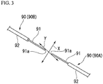
- each of a pair of optical fibers 90 which is fusion-spliced by the fusion splicer 1 with which the optical fiber fusion splicing apparatus according to the present invention is provided is an optical fiber in which a core wire 91 made of glass is covered and integrated with a resin coating 92 made of a synthetic resin material. Further, in the pair of optical fibers 90A and 90B which are fusion-spliced, the resin coating 92 is removed in advance, whereby the vicinity of a tip 91a of each of the core wires 91 which are fusion-spliced is exposed. Further, although detailed illustration is omitted in FIG. 3 , the core wire 91 is composed of a core of a central portion and a clad of a peripheral portion.
- connection portion is covered with a sleeve, and the sleeve is heated and shrunk by the optical fiber connection portion reinforcing heater described above, whereby the connection portion is reinforced.
- FIGS. 1 to 5 an optical fiber fusion splicer of a first embodiment of the present invention will be described in detail using FIGS. 1 to 5 .
- FIG. 8 which is the overall perspective view of an optical fiber fusion splicing apparatus of the related art, as necessary.
- the drawings which are referred to in the present embodiment are sometimes appropriately used in other embodiments as well, and for example, even in a case where disposition positions or the like of configurations are different from each other in the embodiments, configurations having the same function are sometimes described with the same reference numerals applied thereto.
- each drawing which is referred to in the following description is for schematically describing the fusion splicer with which the optical fiber fusion splicing apparatus of the present embodiment is provided, and therefore, there is a case where a positional relationship in the right-left direction or the up-down direction in the drawing is different in the respective drawings.
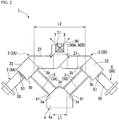
- the fusion splicer 1 with which the optical fiber fusion splicing apparatus of the present embodiment is provided is for aligning the tips 91a of the pair of optical fibers 90 (90A and 90B), thereby bringing the tips 91a into contact with each other, and fusion-splicing the core wires 91 by discharge heating, as shown in FIGS. 1 and 2 ( FIG. 3 is also referred to).
- the fusion splicer 1 is provided with a pair of right and left V-grooved stands 2 (2A and 2B) having V-grooves 21 for performing the positioning of the pair of optical fibers 90A and 90B, a pair of elastic members 3 (3A and 3B) respectively supporting the pair of V-grooved stands 2A and 2B, a fixed base 4 to which the pair of V-grooved stands 2A and 2B is fixed through the pair of elastic members 3A and 3B, and a pair of micrometers 5 (5A and 5B) aligning the tips 91a of the pair of optical fibers 90A and 90B by pressing the pair of V-grooved stands 2A and 2B from forward and backward directions.
- the fusion splicer 1 of the present embodiment is provided with a top base section 10 which covers at least a portion of the above-described elastic alignment mechanism from above, a pair of fiber clamps 6 (in FIG. 4B , only a fiber clamp 6B on one side is shown) which is provided so as to be able to move in the right-left direction with gripping each of the optical fibers, and a pair of movable stages 7 (7A and 7B) making the pair of fiber clamps 6 approach each other or be separated from each other in the right-left direction, as shown in FIGS. 4A, 4B , and 5 .
- the fusion splicer 1 is provided with a pair of illumination lamps for observation 8 (8A and 8B) emitting observation light toward the tips 91a of the pair of optical fibers 90A and 90B, a pair of lenses for observation 9 (9A and 9B) which is disposed to face the pair of illumination lamps for observation 8A and 8B and detects an alignment state of the tips 91a of the pair of optical fibers 90A and 90B, and a pair of electrode rods 15 (15A and 15B) disposed so as to face each other on both sides of the tips 91a of the pair of optical fibers 90A and 90B.
- a pair of mounting portions 42 (42A and 42B) of the fixed base 4 configuring the above-described elastic alignment mechanism is fixed to mounting bosses 12 provided so as to protrude downward from the top base section 10, by bolts 13.
- a lid portion 11 which performs opening and closing of the inside of the apparatus when setting the pair of optical fibers 90A and 90B is provided on the top base section 10. Further, clamp members (not shown) are provided on the inner surface side of the lid portion so as to correspond to the pair of optical fibers 90A and 90B. Then, the fusion splicer 1 is accommodated in a casing (not shown) (also refer to, for example, FIG. 8 showing the related art).
- the pair of V-grooved stands 2A and 2B has the V-grooves 21 for bringing the tips 91a of the pair of optical fibers 90A and 90B into contact with each other while positioning the tips 91a, as described above, and is provided in a pair on the right and left, as shown in the perspective view of FIG. 1 .
- Each of the V-grooved stands 2A and 2B is composed of a base portion 22 to which each of the elastic members 3A and 3B (details will be described later) is connected, and an arm portion 23 extending from the base portion 22, and the V-groove 21 is provided in the arm portion 23. Further, the pair of V-grooved stands 2A and 2B is disposed such that the V-grooves 21 provided therein communicate with each other.
- the pair of optical fibers 90A and 90B as shown in FIG. 3 is accommodated and set in the V-grooves 21.
- the optical fibers 90A and 90B are set in the V-grooves 21 having a shape cut into a V-shape, whereby the pair of optical fibers 90A and 90B enters a state of being able to appropriately move in the X direction and the Y direction shown by arrows in FIG. 2 (also refer to FIG. 3 ).
- Each of the pair of elastic members 3A and 3B is a member formed into the form of an elastically deformable plate supporting each of the pair of V-grooved stands 2A and 2B having the above configuration, and in an example shown in FIG. 1 and the like, each of the elastic members 3A and 3B is composed of two plate-shaped members provided parallel to each other.
- an elastic material which has been used as a member in the relevant field in the past can be used without being limited in any way, and it is possible to adopt, for example, nickel silver or the like which is an alloy material composed of copper, zinc, and nickel.
- the pair of elastic members 3A and 3B is mounted on the fixed base 4, whereby the pair of V-grooved stands 2A and 2B is fixed to the fixed base 4 through the pair of elastic members 3A and 3B, and thus the fixed base 4 functions as a base configuring the elastic alignment mechanism which is described in the present embodiment.
- each of the pair of elastic members 3A and 3B has a structure integrated through the fixed base 4.
- the pair of mounting portions 42 (42A and 42B) for mounting the fixed base 4 on the top base section 10 is provided so as to protrude in a flat plate shape (in FIGS. 4A and 4B , for convenience of description, illustration of the pair of mounting portions 42A and 42B is omitted).
- a through-hole 43 is formed in each of the pair of mounting portions 42A and 42B.
- the pair of elastic members 3A and 3B is provided so as to extend upward from the fixing base portions 41 of the fixed base 4 while being respectively inclined in the forward and backward directions, that is, so as to be orthogonal to a longitudinal direction of the pair of optical fibers 90A and 90B, and with two elastic members of each of the pair of elastic members 3A and 3B being parallel to each other.
- the pair of elastic members 3A and 3B is disposed at the fixing base portions 41 of the fixed base 4 at positions shifted in the right-left direction of the fixed base 4 and is disposed such that the pair of elastic members 3A and 3B and the pair of V-grooved stands 2A and 2B connected to the elastic members 3A and 3B do not interfere with each other.
- each of the pair of elastic members 3A and 3B has a configuration in which two plate-shaped members are provided parallel to each other, whereby when the pair of elastic members 3A and 3B is elastically deformed, the pair of optical fibers 90A and 90B guided to the V-grooves 21 of the pair of V-grooved stands 2A and 2B connected to the pair of elastic members 3A and 3B moves substantially in parallel. Further, as shown in FIGS.
- the pair of elastic members 3A and 3B is configured so as to be orthogonal to each other while being respectively inclined upward, thereby being disposed to be orthogonal to the movement in the X direction or the Y direction of the pair of right and left optical fibers 90A and 90B shown by the arrows in FIG. 3 .
- the fusion splicer 1 is configured such that when viewed from the right and left end portions 4a and 4b of the fixed base 4, a distance L1 between one end portions 3a and 3a of the pair of elastic members 3A and 3B in the fixing base portions 41 is narrower than a distance L2 between the other end portions 3b and 3b on which the pair of V-grooved stands 2A and 2B is mounted.
- the distances L1 and L2 indicate, in one end portions 3a and 3a and the other end portions 3b and 3b of the pair of elastic members 3A and 3B each composed of two plate-shaped members, distances between the intermediate positions between joined portions of the two plate-shaped members.
- the pair of elastic members 3A and 3B which is provided so as to extend upward while being inclined, as described above, can be configured so as to be fixed to the fixing base portions 41 of the fixed base 4 with the elastic member 3A and 3B inclined in directions orthogonal to each other, that is, directions intersecting at an angle of 90°.
- the pair of micrometers 5 is for finely moving the pair of V-grooved stands 2A and 2B with respect to each other while elastically deforming the elastic members 3A and 3B, by pressing the pair of V-grooved stands 2A and 2B, more specifically, side walls 22a of the base portions 22 of the V-grooved stands 2A and 2B in the forward and backward directions.
- the micrometer 5 a micrometer which has been used for alignment of optical fibers in the relevant field in the past can be adopted without any limitation.
- the micrometer 5 operates such that a tip 51 protrudes or is accommodated inside by a motor (not shown) provided in a main body 50, as in an illustrated example. Due to such an operation, the micrometer 5 aligns the tips 91a of the optical fibers 90A and 90B by appropriately moving the tips 91a of the optical fibers 90A and 90B accommodated in the V-grooves 21 of the V-grooved stands 2A and 2B by pressing and finely moving the side walls 22a of the base portions 22 of the V-grooved stands 2A and 2B, as described above.
- the fiber clamps 6 are mounted so as to be movable with respect to the top base section 10 and are disposed to be separated from each other with the tips 91a of the pair of optical fibers 90A and 90B interposed therebetween in the right-left direction, that is, a direction parallel to the pair of optical fibers 90A and 90B, as described above.
- the fiber clamps 6 are provided so as to be able to move in the right-left direction with gripping each of the pair of optical fibers 90A and 90B, and respectively grip the pair of optical fibers 90A and 90B when fusion-splicing the tips 91a of the pair of optical fibers 90A and 90B.
- the fiber clamps 6 are a pair of right and left clamp members which includes a fiber clamp (not shown) gripping the optical fiber 90A on one side, and the fiber clamp 6B gripping the optical fiber 90B on the other side. Further, although detailed illustration is omitted, the fiber clamp 6 has a configuration capable of gripping (clamping) each of the pair of optical fibers 90A and 90B inserted therein, by a clamp which can be opened and closed by a biasing member such as a torsion coil spring or a double torsion spring, for example.
- a biasing member such as a torsion coil spring or a double torsion spring, for example.
- the pair of movable stages 7A and 7B is provided below the pair of fiber clamps 6 and is for driving the pair of fiber clamps 6 so as to approach each other or be separated from each other in the right-left direction, and for example, a motor, an electromagnet, a solenoid, or the like (none of which is shown) can be used as a drive source. Then, although detailed illustration is omitted, the pair of fiber clamps 6 described above is respectively fixed to the pair of movable stages 7A and 7B by using, for example, a bolt or the like.
- the pair of fiber clamps 6 described above is made to be able to move so as to come close to or be separated from the V-grooves 21 of the pair of V-grooved stands 2A and 2B, which are disposed between the pair of fiber clamps 6, due to the pair of movable stages 7A and 7B moving so as to approach each other or be separated from each other for each of the pair of fiber clamps.
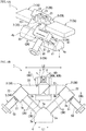
- each of the pair of movable stages 7A and 7B is disposed so as to be separated from each of the pair of V-grooved stands 2A and 2B disposed above the fixed base 4 at positions shifted in the right-left direction of the fixed base 4. In this manner, compact disposition is made without the pair of movable stages 7A and 7B and the pair of V-grooved stands 2A and 2B interfering with each other in the right-left direction of the fixed base 4.
- the pair of illumination lamps for observation 8A and 8B is disposed on both sides of the tips 91a of the pair of optical fibers 90A and 90B brought into contact with each other between the pair of fiber clamps 6, on the lower side of the top base section 10, and emits observation light toward the tips 91a.
- an illumination lamp made of a light-emitting element such as an LED which has been used in the relevant field in the past, can be used without any limitation.
- the pair of lenses for observation 9A and 9B is disposed to face the pair of illumination lamps for observation 8A and 8B on both sides of the tips 91a of the pair of optical fibers 90A and 90B brought into contact with each other between the pair of fiber clamps 6, on the lower side of the top base section 10.
- the lenses for observation 9A and 9B detect an alignment state of the tips 91a of the pair of optical fibers 90A and 90B brought into contact with each other, by incident light from the illumination lamps for observation 8A and 8B.
- each of the pair of lenses for observation 9A and 9B is mounted on the fixed base 4 by means such as screwing.
- the alignment state of the tips 91a of the pair of optical fibers 90A and 90B detected by the pair of lenses for observation 9A and 9B is input to a control section (not shown) as an alignment signal.
- the control section controls the rotation of a motor (not shown) provided in each of the pair of micrometers 5A and 5B by arithmetically processing the alignment signals from the pair of lenses for observation 9A and 9B, and thus adjusts the amount of protrusion of the tip 51.
- each of the pair of V-grooved stands 2A and 2B is appropriately finely moved in the X direction or the Y direction shown by the arrows in FIG.
- the tips 91a of the pair of optical fibers 90A and 90B set in the respective V-grooves 21 of the pair of V-grooved stands 2A and 2B are aligned with a high degree of accuracy.
- the pair of electrode rods 15A and 15B is electrode members which are disposed to be separated from each other so as to face each other on both sides of the tips 91a of the pair of optical fibers 90A and 90B brought into contact with each other between the pair of fiber clamps 6, and discharge-heats the tips 91a.
- the electrode rods 15A and 15B are disposed so as to face each other in the front to back direction, that is, in the direction orthogonal to the pair of optical fibers 90A and 90B with tips 15a separated from the tips 91a of the pair of optical fibers 90A and 90B by a predetermined distance. Further, each of the tips 15a of the pair of electrode rods 15A and 15B has a tapered shape.
- the fusion splicer 1 performs fusion by heating the tips 91a of the pair of optical fibers 90A and 90B by discharge heating by the pair of electrode rods 15A and 15B.
- the top base section 10 is a member which is provided so as to cover at least part of the pair of V-grooved stands 2A and 2B, the pair of elastic members 3A and 3B, the fixed base 4, and the micrometers 5 from above, as described above, and formed of a resin material or the like into the form of a flat plate.
- a hole portion 10A is open, whereby the V-grooves 21 of the pair of V-grooved stands 2A and 2B are exposed from above.
- the lid portion 11 is provided on the top base section 10, and although illustration is omitted, the lid portion 11 is mounted on the top base section 10 so as to be able to be opened and closed by, for example, a hinge member or the like.
- the mounting boss 12 for fixing the fixed base 4 is provided so as to protrude downward.
- the mounting boss 12 is formed into the form of a truncated cone, the diameter of which is reduced toward the lower side, and a bolt mounting hole (not shown) is provided in the tip face 12a. Then, the bolt 13 is screwed into the bolt mounting hole, whereby the pair of mounting portions 42A and 42B provided in the fixed base 4 is fixed to the mounting bosses 12 by the bolts 13. In this manner, the fixed base 4 is mounted on the top base section 10.
- the fusion splicer 1 of the present embodiment is provided with each configuration described above, whereby very excellent effects in which it is possible to reduce the size and the weight of the entire elastic alignment mechanism such as the V-grooved stand or the fixed base while suppressing occurrence of distortion in the fixed base to which the elastic member is connected, and maintenance work becomes easy, are obtained.
- the operation and effects which are obtained by the fusion splicer 1 of the present embodiment will be described in comparison with the case of the fusion splicer having the configuration of the related art.
- the distance B between the connection portions of the pair of elastic members 103A and 103B to the fixed base 104 is large, and therefore, when deforming the elastic member 103A by the micrometer 105A, distortion occurs in the fixed base 104, and thus there is a concern that the fixed base 104 may be damaged or alignment accuracy may be reduced.
- the fusion splicer 1 of the present embodiment due to the configuration in which the distance L1 between one end portions 3a and 3a of the pair of elastic members 3A and 3B in the fixed base 4 is short, it is possible to reduce the size of the fixed base 4, and therefore, occurrence of distortion in the fixed base 4 can be suppressed. Therefore, breakage of the optical fiber fusion splicer or a decrease in alignment accuracy of the pair of optical fibers 90A and 90B can be prevented and it becomes possible to attain a reduction in the size and the weight of the entire optical fiber fusion splicing apparatus.
- the fusion splicer of the related art has a configuration in which the pair of V-grooved stands 102A and 102B extends up and down in order to avoid the lenses for observation 109 (not shown), or guides (not shown) for driving forward the fiber clamps 106A and 106B (refer to FIG. 8 ), and therefore, there is also a problem in that the height of the entire mechanism is increased.
- the pair of elastic members 3A and 3B is fixed so as to extend upward from the fixed base 4 while being inclined in the forward and backward directions and is disposed at positions shifted in the right-left direction and the connection portions of the pair of V-grooved stands 2A and 2B to the pair of elastic members 3A and 3b are disposed at positions away from a fusion splicing portion in which the tips 91a of the pair of optical fibers 90A and 90B are brought into contact with each other.
- connection portions of the elastic members 103A and 103B to the V-grooved stands 102A and 102B are disposed in the vicinity of a fusion splicing portion between the pair of optical fibers 90A and 90B, and therefore, there is also a case where the pair of elastic members 103A and 103B interfere with the fiber clamps 106A and 106B (refer to FIG. 8 ) or driving stages for driving forward the fiber clamps 106A and 106B.
- a drive mechanism such as the micrometer 105A is disposed on the lower side of the apparatus, and therefore, there is also an concern in that it is difficult to perform maintenance work from above the apparatus.
- the fusion splicer 1 of the present embodiment has a configuration in which the pair of elastic members 3A and 3B is fixed so as to extend upward while being inclined in the forward and backward directions and is disposed at positions shifted in the right-left direction, and therefore, drive mechanisms such as the pair of micrometers 5A and 5B for elastically deforming the pair of elastic members 3A and 3B can be disposed on the upper side, backward and forward away from a fusion splicing portion. In this manner, it becomes easy to perform maintenance work of the drive mechanisms from above the optical fiber fusion splicing apparatus, and therefore, both effects of a reduction in the size of the apparatus and improvement in maintainability are obtained.
- the fixed base 104 is mounted on a top base 110 by a suspension member 114 and a screw member (not shown), and although illustration is omitted in FIG. 11 , a structure is made in which lenses for observation which are provided in a pair are also mounted on the top base 110 by screwing or the like.
- a problem in terms of impact resistance such as there being a concern that, for example, in a case where the optical fiber fusion splicing apparatus is dropped, or the like, a large impact may be particularly transmitted to lenses for observation, thereby damaging the lenses for observation.
- the fusion splicer 1 of the present embodiment due to the configuration shown in FIGS. 1 and 2 , it is possible to reduce a height, and therefore, it becomes possible to further optimize a disposition form in the optical fiber fusion splicing apparatus. That is, rather than mounting the lens for observation on the top base section, as in the configuration of the related art, for example, in an example shown in FIG. 5 , it becomes possible to adopt a configuration in which the pair of lenses for observation 9A and 9B is mounted and supported on the fixed base 4.
- the pair of optical fibers 90A and 90B is set in the V-grooves 21 respectively provided in the pair of V-grooved stands 2A and 2B such that the tips 91a roughly face each other is created.
- clamp members (not shown) provided in the pair of fiber clamps 6 are in an open state, and a state where the pair of optical fibers 90A and 90B is placed in the opened clamp members is created.
- the lid portion 11 is closed, and the fusion splicer 1 is operated by operating the operation section (not shown), whereby the tips 91a of the pair of optical fibers 90A and 90B are fusion-spliced to each other.
- the pair of fiber clamps 6 moves toward the sides of the V-grooves 21 provided in the pair of V-grooved stands 2A and 2B according to the movement of the pair of movable stages 7A and 7B, whereby the tips 91a slide in the V-grooves 21, thereby being disposed in a state of facing each other. Further, the alignment state of the tips 91a at this time is detected by the pair of lenses for observation 9A and 9B disposed to face the pair of illumination lamps for observation 8A and 8B and an alignment signal is input to the control section (not shown).
- the control section arithmetically processes the input alignment signal, as described above, and appropriately controls the amount of protrusion of the tip 51 while controlling the rotation of the motor (not shown) provided in each of the pair of micrometers 5A and 5B, thereby finely moving each of the pair of V-grooved stands 2A and 2B in the X direction or the Y direction shown by the arrows in FIG. 2 . In this manner, the tips 91a of the pair of optical fibers 90A and 90B set in the V-grooves 21 are aligned.
- the pair of optical fibers 90A and 90B is fusion-spliced to each other by the above procedure.
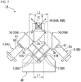
- FIGS. 6 and 7 an optical fiber fusion splicer 1A of a second embodiment of the present invention will be described mainly referring to FIGS. 6 and 7 .
- a portion is described with reference to the same drawings as those in the first embodiment described above, and a common configuration described previously, for example, the pair of micrometers 5 which aligns the tips 91a of the pair of optical fibers 90A and 90B while elastically deforming the elastic members by pressing the V-grooved stands, or the like is denoted by the same reference numeral and the detailed description thereof is omitted.
- the fusion splicer 1A of the present embodiment is for aligning the tips 91a of the pair of optical fibers 90A and 90B, thereby bringing the tips 91a into contact with each other, and fusion-splicing the core wires of the pair of optical fibers by discharge heating, similar to the fusion splicer 1 of the first embodiment.
- the fusion splicer 1A is provided with a pair of right and left V-grooved stands 20A and 20B having the V-grooves 21 for bringing the tips 91a of the pair of optical fibers 90A and 90B into contact with each other while positioning the tips 91a, the pair of elastic members 3A and 3B respectively supporting the pair of V-grooved stands 20A and 20B and formed into the form of an elastically deformable plate, and a fixed base 40 on which the pair of elastic members 3A and 3B is mounted, whereby the pair of V-grooved stands 20A and 20B is fixed thereto through the pair of elastic members 3A and 3B, and which is long in the right-left direction.
- the fusion splicer 1A is provided with the pair of micrometers 5A and 5B for aligning the tips 91a of the pair of optical fibers 90A and 90B by finely moving the pair of V-grooved stands 20A and 20B while elastically deforming the pair of elastic members 3A and 3B by pressing the pair of V-grooved stands 20A and 20B from the forward and backward directions.
- the fusion splicer 1A is roughly common to the fusion splicer 1 of the first embodiment described above in that the pair of V-grooved stands 20A and 20B is disposed such that the V-grooves 21 respectively provided in the V-grooved stands 20A and 20B communicate with each other and the fusion splicer 1A has each of these configurations.
- the fusion splicer 1A of the present embodiment has a configuration which is different from that of the fusion splicer 1 of the first embodiment shown in FIGS. 1 , 2 and the like in that a pair of fixing base portions 41A and 41B disposed parallel to each other in the right-left direction is provided in the fixed base 40 and the pair of elastic members 3A and 3B is provided so as to extend upward from the pair of fixing base portions 41A and 41B provided in the fixed base 40, while intersecting each other and being inclined in the forward and backward directions, and is disposed at positions shifted in the right-left direction of the fixed base 40, as shown in FIGS. 6 and 7 .
- a configuration is made such that when viewed from the left and right end portions 40a and 40b of the fixed base 40, the distance L1 between one end portions 3a and 3a of the pair of elastic members 3A and 3B in the pair of fixing base portions 41A and 41B is narrower than the distance L2 between the other end portions 3b and 3b on which the pair of V-grooved stands 20A and 20B is mounted.
- the fusion splicer 1A of the present embodiment is greatly different from the fusion splicer 1 of the first embodiment shown in FIGS. 1 and 2 and the like in that the pair of elastic members 3A and 3B supporting the pair of V-grooved stands 20a and 20B is disposed so as to cross each other, as shown in the side view of FIG. 7 .
- the fusion splicer 1A has a configuration in which the pair of elastic members 3A and 3B is fixed so as to extend upward from the fixed base 40 while being inclined in the forward and backward directions and is disposed at positions shifted in the right-left direction, similar to the fusion splicer 1 of the first embodiment.
- the pair of elastic members 3A and 3B does not interfere with the pair of right and left fiber clamps 6, the pair of movable stages 7A and 7B, or the like, and therefore, it is not necessary to increase the height of the pair of V-grooved stands 20A and 20B. Therefore, it is possible to reduce the height of the fusion splicer 1A, and thus a reduction in the size and the weight of the entire optical fiber fusion splicing apparatus becomes possible.
- the distance L1 between one end portions 3a and 3a, that is, the connection portions, of the pair of elastic members 3A and 3B in the fixed base 40 is configured to be short, whereby it becomes possible to reduce the size of the fixed base 40.
- occurrence of distortion in the fixed base 40 can be suppressed, and therefore, breakage of the optical fiber fusion splicer or a decrease in alignment accuracy of the pair of optical fibers 90A and 90B can be prevented, and it becomes possible to attain a reduction in the size and the weight of the entire optical fiber fusion splicing apparatus.
- the pair of elastic members 3A and 3B is disposed so as to extend upward while being inclined in the forward and backward directions and at positions shifted in the right-left direction, and therefore, the drive mechanisms such as the pair of micrometers 5A and 5B can be disposed on the upper side, backward and forward away from a fusion splicing portion. In this manner, as described above, it becomes easy to perform maintenance word of each drive mechanism from above the optical fiber fusion splicing apparatus, and thus both effects of a reduction in the size of the apparatus and improvement in maintainability are obtained.
- optical fiber fusion splicing apparatus is not limited to the optical fiber fusion splicing apparatus which is provided with the fusion splicer 1 or 1A having the configuration described in each of the embodiments described above, and it is possible to apply various changes and additions without departing from the scope described in the appended claims of the present invention.
- the pair of micrometers 5A and 5B for performing alignment of the tips 91a of the pair of optical fibers 90A and 90B by pressing the pair of V-grooved stands in terms of being able to further reduce the size of the entire fusion splicer, it is preferable to adopt, for example, a micrometer reduced in size including a drive mechanism such as a motor.
- the alignment may be performed by alignment of an outer diameter including a clad.
- an optical component for performing the alignment of the tips 91 a be a simple and small component, and thus it becomes possible to further reduce the size and the weight of the fusion splicer.
Description
- Priority is claimed on Japanese Patent Application No.
2014-217246, filed on October 24, 2014 - The present invention relates to an optical fiber fusion splicer and an optical fiber fusion splicing apparatus which is provided with the optical fiber fusion splicer.
- When performing a fusion splice of an optical fiber, in general, the fusion splice is performed in the following procedure by using an optical fiber fusion splicing apparatus.
- (1) An optical fiber core wire is extracted from an optical fiber cable.
- (2) A resin coating (a tip) covering the extracted optical fiber core wire is removed by an optical fiber coating removal tool.
- (3) Resin coating debris remaining on the surface of glass (a bare optical fiber) of the optical fiber core wire with the coating of the tip removed therefrom is removed with a cloth or paper wetted with alcohol.
- (4) The optical fiber core wire which has been cleaned is cut by an optical fiber cutter.
- (5) The cut optical fiber core wires are fusion-spliced by the optical fiber fusion splicing apparatus.
- (6) The fusion-spliced optical fiber core wire is covered with a heat-shrinkable reinforcement sleeve and heated and reinforced by a heater of the fusion splicing apparatus.
- (7) The heated and reinforced optical fiber core wire is stored in a storage tray of a connection portion storage case.
- As an optical fiber fusion splicer which is used in the process (5) described above, for example, a device (a single-core machine) for fusion-splicing a pair of single-core optical fibers by discharge heating between a pair of electrode rods, or a device (a multi-core machine) for fusion-splicing end portions of a pair of multi-core optical fibers (a tape fiber) together by discharge heating between a pair of electrode rods is provided.
- In the related art, as an optical fiber fusion splicer which is used for a single-core optical fiber, for example, an optical fiber fusion splicer having a function and a configuration as shown in
FIG. 8 and described below is widely used. - (a) A pair of optical fibers (not shown) is illuminated with one or two illumination lamps for observation from one direction or two directions and the optical fibers are observed in one axis or two axes from the each direction by one or two lenses for observation (not shown) or one or two cameras (not shown).
- (b) Glass portions (core wires) of the pair of optical fibers with coatings removed therefrom are disposed on a pair of V-
grooves 121 and gripped by a pair offiber clamps grooves 121 from above. - (c) The
fiber clamps - (d) A
windshield cover 111 has a structure of covering a pair ofelectrode rods grooves 121, and thefiber clamps - When fusion-splicing right and left optical fibers which are paired, by using an optical fiber
fusion splicing apparatus 100 of the related art as shown inFIG. 8 , in order to reduce a transmission loss of a connection portion, alignment is performed so as to precisely match the axes of the optical fibers, and thereafter, the optical fibers are advanced and fused. At this time, an operation to align the axes of the optical fibers can be performed by makingtips 91a ofcore wires 91 of a pair ofoptical fibers FIG. 3 , and then finely moving theoptical fibers - As a mechanism which is used for the alignment of the optical fibers, as described above, for example, a
fusion splicer 101 which is provided with an elastic alignment mechanism having an elastically deformable elastic member, as shown inFIGS. 9 and10 , is proposed. In thefusion splicer 101 shown inFIGS. 9 and10 , two plate-shapedelastic members 103A are disposed so as to extend obliquely upward from the right side of afixed base 104 inFIG. 9 , and the tips thereof are connected to a V-grooved stand 102A with a V-groove 121 provided therein. Further, similar to the above, twoelastic members 103B are disposed so as to extend obliquely upward from the left side of afixed base 104 inFIG. 9 and the tips thereof are connected to a V-groovedstand 102B with the V-groove 121 provided therein. Further, theelastic members fixed base 104, from the front and the back in a longitudinal direction (the right-left direction when viewed from the front side of the optical fiberfusion splicing apparatus 100 shown inFIG. 8 ) of thefixed base 104. In this manner, thefusion splicer 101 shown inFIGS. 9 and10 has a structure in which right and left aligning structures are integrated with each other through thefixed base 104. - Further, the
elastic members FIGS. 9 and10 are disposed such that two elastic members of each of theelastic members elastic members 103A and theelastic members 103B are orthogonal to each other. In this manner, the two elastic members of each of theelastic members elastic members grooves 121 of the pair of V-grooved stands 102A and 102B connected to the tips moves substantially in parallel. Further, the right and leftelastic members optical fibers FIG. 3 are also orthogonal to each other. - Then, in the
fusion splicer 101 shown inFIGS. 9 and10 , the alignment of thetips 91a of the pair ofoptical fibers FIG. 3 is performed by finely moving the V-grooves 121 provided in the V-grooved stands elastic members grooved stands micrometers fusion splicer 101 of the related art shown inFIGS. 9 and10 , a configuration is made such that a distance A between connection portions of the pair ofelastic members grooved stands elastic members fixed base 104. Here, inFIG. 10 , each of the distances A and B indicates, in the pair ofelastic members - Here, as a structure to align the tips of a pair of optical fibers in fusion-splicing the tips, a fusion splicer as described in Japanese Unexamined Utility Model Application, First Publication No.
S58-67306 - Further, as a structure to align the tips of a pair of optical fibers, a fusion splicer as described in Japanese Unexamined Patent Application, First Publication No.
S63-108307 - In addition, as a structure to align the tips of a pair of optical fibers, a fusion splicer as described in Japanese Unexamined Patent Application, First Publication No.
H08-62446 - However, in the
fusion splicer 101 of the related art as shown inFIGS. 9 and10 , for example, when theelastic members 103A are deformed by pressing by themicrometer 105A, since the distance B between the connection portions of the pair ofelastic members fixed base 104 is large, if the rigidity of thefixed base 104 made of a resin molding product or the like is low, distortion occurs in thefixed base 104, and thus there is a concern that the elastic alignment mechanism may break down or alignment accuracy may be reduced. - In addition, also in the fusion splicer which is provided with the elastic alignment mechanism described in each of Japanese Unexamined Utility Model Application, First Publication No.
S58-67306 S63-108307 H08-62446 - Moreover, in the case of the
fusion splicer 101 shown inFIGS. 9 and10 , as described above, the distance B between the connection portions of the pair ofelastic members fixed base 104 is larger than the distance A between the connection portions of the pair ofelastic members grooved stands fixed base 104 is increased and the weight is also increased. Further, also in the fusion splicer described in each of Japanese Unexamined Utility Model Application, First Publication No.S58-67306 S63-108307 H08-62446 fixed base 104 is increased and the weight is also increased. - Furthermore, in the
fusion splicer 101 shown inFIGS. 9 and10 , in order to avoid lenses for observation 109 (not shown) which are disposed in the front and the back of thefusion splicer 101, and guides (not shown) which are disposed in a pair on the right and left sides, whereby thefiber clamps FIG. 8 ) are driven forward, the pair of V-grooved stands FIG. 9 ), and theelastic members fixed base 104 from the V-grooved stands H08-62446 - In addition, in the configuration of the fusion splicer of the related art, the connection portions of the
elastic members grooved stands elastic members fiber clamps FIG. 8 ) or drive stages (not shown) for driving forward thefiber clamps grooves 121 on the upper side and dispose theelastic members micrometer 105A for elastically deforming the pair ofelastic members JP 2004/354636 JP H07 43548 A - The present invention has been made in view of the above circumstances and provides an optical fiber fusion splicer in which it is possible to reduce the size and the weight of the entire elastic alignment mechanism such as a V-grooved stand or a fixed base while suppressing occurrence of distortion in the fixed base to which an elastic member is connected, and maintenance work is easy, and an optical fiber fusion splicing apparatus using the optical fiber fusion splicer.
- The first aspect of the present invention is an optical fiber fusion splicer which aligns tips of a pair of optical fibers and butts the tips each other, and fusion-splices core wires of the pair of optical fibers by discharge heating as defined in
claim 1. - The second aspect of the present invention is the optical fiber fusion splicer according to the first aspect, wherein the fixed base may be further provided with a pair of fixing base portions disposed parallel to each other in the right-left direction, respective ones of the pair of elastic members extending upward from respective ones of the pair of fixing base portions provided in the fixed base, while intersecting each other and being inclined in respective ones of directions orthogonal to each other, and is disposed at positions shifted in the right-left direction of the fixed base, and when viewed from the right and left end portions of the fixed base, a distance L1 between the first end portions of the pair of elastic members fixed to the pair of fixing base portions is narrower than a distance L2 between the second end portions of the pair of elastic members supporting the pair of V-grooved stands.
- The third aspect of the present invention is that, in the optical fiber fusion splicer according to any one of the first to second aspects, the optical fiber fusion splicer may further include: a top base section which is provided so as to cover at least part of the pair of V-grooved stands, the pair of elastic members, the fixed base, and the micrometers from above; each fiber clamps mounted on the top base section, disposed to be separated from each other with the tips of respective ones of the pair of optical fibers interposed therebetween in the right-left direction, and provided so as to be able to move in the right-left direction with gripping each of the pair of optical fibers; a pair of movable stages each movable stage provided below respective ones of the pair of fiber clamps approaches each other or be separated from each other in the right-left direction; a pair of illumination lamps for observation, each illumination lamp disposed on both sides of the tips of respective ones of the pair of optical fibers which are butt each other between the pair of fiber clamps on an upper side of the top base section, and emits observation light toward the tips; a pair of lenses for observation, each lens mounted on the fixed base so as to be disposed to face respective ones of the pair of illumination lamps for observation on both sides of the tip of respective ones of the pair of optical fibers which is butt each other between the pair of fiber clamps on the lower side of the top base section, and detects an alignment state of the tips of the pair of optical fibers brought into contact with each other, by incident light from the illumination lamps for observation; and a pair of electrode rods, each electrode rod disposed to be separated from each other so as to face each other on both sides of the tip of respective ones of the pair of optical fibers which are butt each other between the pair of fiber clamps, and discharge-heats the tip of the pair of optical fibers, wherein the fixed base may be fixed to a mounting boss provided so as to protrude downward from the top base section.
- The fourth aspect of the present invention is that, in the optical fiber fusion splicer according to the third aspect, each movable stages may be disposed above the fixed base so as to be separated from respective ones of the pair of V-grooved stands disposed at positions shifted in the right-left direction of the fixed base.
- The fifth aspect of the present invention is an optical fiber fusion splicing apparatus including the optical fiber fusion splicer according to any one of the first to fourth aspects.
- According to the above aspects of the present invention, the distance L1 between one end portions of the pair of elastic members in the fixed base is configured to be short, whereby it becomes possible to reduce the size of the fixed base, and therefore, it is possible to suppress occurrence of distortion in the fixed base. In this manner, breakage of the optical fiber fusion splicer or a decrease in alignment accuracy of the optical fibers can be prevented and it becomes possible to attain a reduction in the size and the weight of the entire optical fiber fusion splicing apparatus.
- In addition, the pair of elastic members is fixed so as to extend upward from the fixed base while being respectively inclined in the forward and backward directions and is disposed at positions shifted in the right-left direction and a connection portion of the V-grooved stand to the elastic member is disposed at a position away from a fusion splicing portion in which the tips of the pair of optical fibers are brought into contact with each other, and therefore, there is no interference with the right and left fiber clamps, the movable stages driving forward the fiber clamps, or the like. In this manner, it is not necessary to increase the height of the V-grooved stand, and thus it becomes possible to reduce the height of the optical fiber fusion splicer. Therefore, a reduction in the size and the weight of the entire optical fiber fusion splicing apparatus becomes possible.
- Furthermore, the pair of elastic members is fixed so as to extend upward while being inclined in the forward and backward directions and is disposed at positions shifted in the right-left direction, and therefore, drive mechanisms such as the micrometers for elastically deforming the elastic members can be disposed on the upper side, backward and forward away from a fusion splicing portion. Therefore, it becomes easy to perform maintenance work of the drive mechanisms from above the optical fiber fusion splicing apparatus, and thus maintainability is improved.
-
-
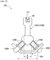
FIG. 1 is a perspective view showing an elastic alignment mechanism of an optical fiber fusion splicer with which an optical fiber fusion splicing apparatus according to an embodiment of the present invention is provided. -
FIG. 2 is a side view showing the elastic alignment mechanism of the optical fiber fusion splicer with which the optical fiber fusion splicing apparatus according to the embodiment of the present invention is provided. -
FIG. 3 is a perspective view showing a pair of optical fibers which is aligned by the optical fiber fusion splicer with which the optical fiber fusion splicing apparatus according to the embodiment of the present invention is provided. -
FIG. 4A is a perspective view showing the positional relationship between an elastic member, a V-grooved stand, and a movable stage in the elastic alignment mechanism of the optical fiber fusion splicer with which the optical fiber fusion splicing apparatus according to the embodiment of the present invention is provided. -
FIG. 4B is a side view showing the positional relationship between the elastic member, the V-grooved stand, and the movable stage in the elastic alignment mechanism of the optical fiber fusion splicer with which the optical fiber fusion splicing apparatus according to the embodiment of the present invention is provided. -
FIG. 5 is a diagram describing the elastic alignment mechanism of the optical fiber fusion splicer with which the optical fiber fusion splicing apparatus according to the embodiment of the present invention is provided, and is a side view describing the positional relationship and the mounting form of the elastic alignment mechanism provided below a top base section. -
FIG. 6 is a perspective view showing an elastic alignment mechanism of an optical fiber fusion splicer with which an optical fiber fusion splicing apparatus according to another embodiment of the present invention is provided. -
FIG. 7 is a side view showing the elastic alignment mechanism of the optical fiber fusion splicer with which the optical fiber fusion splicing apparatus according to another embodiment of the present invention is provided. -
FIG. 8 is an external perspective view showing an example of an optical fiber fusion splicing apparatus of the related art. -
FIG. 9 is a perspective view showing an elastic alignment mechanism of an optical fiber fusion splicer with which the optical fiber fusion splicing apparatus of the related art is provided. -
FIG. 10 is a side view showing the elastic alignment mechanism of the optical fiber fusion splicer with which the optical fiber fusion splicing apparatus of the related art is provided. -
FIG. 11 is a side view describing the positional relationship between the elastic alignment mechanism and a top base and the mounting form of the elastic alignment mechanism in the optical fiber fusion splicer with which the optical fiber fusion splicing apparatus of the related art is provided. - Hereinafter, preferred embodiments of an optical fiber fusion splicer according to the present invention and an optical fiber fusion splicing apparatus in which the optical fiber fusion splicer is used are cited, and each configuration will be described in detail appropriately referring to
FIGS. 1 to 7 (as necessary,FIGS. 8 to 11 showing the related art are also referred to). In the following description, first, an outline of the entire optical fiber fusion splicing apparatus will be described, and thereafter, details of the optical fiber fusion splicer (an elastic alignment mechanism) with which the optical fiber fusion splicing apparatus is provided will be described. - The optical fiber fusion splicing apparatus according to the present invention is provided with an optical fiber fusion splicer (hereinafter, sometimes referred to simply as a fusion splicer) 1 which performs fusion splicing of, for example, an optical fiber, and an optical fiber connection portion reinforcing heater (not shown) for heating and shrinking a sleeve for reinforcement covered on the optical fiber after the fusion splice. Further, the optical fiber fusion splicing apparatus of the present embodiment is provided with a display device (not shown) for displaying a variety of information or the like for a worker, an operation section which is used for condition setting or the like, and the like, in addition to the
fusion splicer 1 and the optical fiber connection portion reinforcing heater. In addition, the optical fiber fusion splicing apparatus is configured by disposing, in an approximately cube-shaped main body section, a built-in device such as means for comprehensively driving thefusion splicer 1 and the optical fiber connection portion reinforcing heater, or a control section, in addition to thefusion splicer 1 and the optical fiber connection portion reinforcing heater. Further, the optical fiber fusion splicing apparatus has a plurality of leg portions at a lower portion of the main body section. As the display device, it is possible to adopt various display types such as a liquid crystal type, an organic EL type, or an electric light type. - Further, the optical fiber fusion splicing apparatus has a movable panel section provided on the front side of the main body section, and the display device or the operation section is disposed on the panel section. The panel section is connected to the main body section through a horizontal pivot shaft provided at an upper portion of the main body section, and a configuration is made in which the display device can be directed in an arbitrary direction within a predetermined angular range by moving the panel section. Further, a worker can move the panel section in a direction that is easy to see the display device.
- In addition, in the optical fiber fusion splicing apparatus according to the present invention, similar to the optical fiber
fusion splicing apparatus 100 of the related art shown inFIG. 8 , the optical fiber connection portion reinforcing heater is disposed at a position on the back side in the optical fiber fusion splicing apparatus, and thefusion splicer 1 is disposed further to the front side than the optical fiber connection portion reinforcing heater. Here, with respect to the front, the back, the right, and the left in the present invention, the side (for example, the left side inFIG. 8 showing the related art) which a worker faces when the worker uses the optical fiber fusion splicing apparatus is set to be the front side, the back side (for example, the right side inFIG. 8 ) of the optical fiber fusion splicing apparatus when viewed from the worker is set to be the back side, and the right and the left of the worker are set to be the right and the left. - As shown in
FIG. 3 , each of a pair of optical fibers 90 (90A and 90B) which is fusion-spliced by thefusion splicer 1 with which the optical fiber fusion splicing apparatus according to the present invention is provided is an optical fiber in which acore wire 91 made of glass is covered and integrated with aresin coating 92 made of a synthetic resin material. Further, in the pair ofoptical fibers resin coating 92 is removed in advance, whereby the vicinity of atip 91a of each of thecore wires 91 which are fusion-spliced is exposed. Further, although detailed illustration is omitted inFIG. 3 , thecore wire 91 is composed of a core of a central portion and a clad of a peripheral portion. - Further, although illustration is omitted, in the pair of
optical fibers tips 91a are fusion-spliced, the connection portion is covered with a sleeve, and the sleeve is heated and shrunk by the optical fiber connection portion reinforcing heater described above, whereby the connection portion is reinforced. - Hereinafter, an optical fiber fusion splicer of a first embodiment of the present invention will be described in detail using
FIGS. 1 to 5 . In addition, configurations which are not shown inFIGS. 1 to 5 are sometimes described while appropriately citingFIG. 8 which is the overall perspective view of an optical fiber fusion splicing apparatus of the related art, as necessary. Further, the drawings which are referred to in the present embodiment are sometimes appropriately used in other embodiments as well, and for example, even in a case where disposition positions or the like of configurations are different from each other in the embodiments, configurations having the same function are sometimes described with the same reference numerals applied thereto. - Further, each drawing which is referred to in the following description is for schematically describing the fusion splicer with which the optical fiber fusion splicing apparatus of the present embodiment is provided, and therefore, there is a case where a positional relationship in the right-left direction or the up-down direction in the drawing is different in the respective drawings.
- The
fusion splicer 1 with which the optical fiber fusion splicing apparatus of the present embodiment is provided is for aligning thetips 91a of the pair of optical fibers 90 (90A and 90B), thereby bringing thetips 91a into contact with each other, and fusion-splicing thecore wires 91 by discharge heating, as shown inFIGS. 1 and2 (FIG. 3 is also referred to). - The
fusion splicer 1 is provided with a pair of right and left V-grooved stands 2 (2A and 2B) having V-grooves 21 for performing the positioning of the pair ofoptical fibers stands base 4 to which the pair of V-groovedstands elastic members tips 91a of the pair ofoptical fibers stands - In addition, the
fusion splicer 1 of the present embodiment is provided with atop base section 10 which covers at least a portion of the above-described elastic alignment mechanism from above, a pair of fiber clamps 6 (inFIG. 4B , only afiber clamp 6B on one side is shown) which is provided so as to be able to move in the right-left direction with gripping each of the optical fibers, and a pair of movable stages 7 (7A and 7B) making the pair of fiber clamps 6 approach each other or be separated from each other in the right-left direction, as shown inFIGS. 4A, 4B , and5 . - Further, the
fusion splicer 1 is provided with a pair of illumination lamps for observation 8 (8A and 8B) emitting observation light toward thetips 91a of the pair ofoptical fibers observation tips 91a of the pair ofoptical fibers tips 91a of the pair ofoptical fibers - In addition, in the
fusion splicer 1, a pair of mounting portions 42 (42A and 42B) of the fixedbase 4 configuring the above-described elastic alignment mechanism is fixed to mountingbosses 12 provided so as to protrude downward from thetop base section 10, bybolts 13. - Further, in the
fusion splicer 1, a lid portion 11 which performs opening and closing of the inside of the apparatus when setting the pair ofoptical fibers top base section 10. Further, clamp members (not shown) are provided on the inner surface side of the lid portion so as to correspond to the pair ofoptical fibers fusion splicer 1 is accommodated in a casing (not shown) (also refer to, for example,FIG. 8 showing the related art). - Hereinafter, each constituent element with which the
fusion splicer 1 of the present embodiment is provided will be described in detail. - The pair of V-grooved
stands grooves 21 for bringing thetips 91a of the pair ofoptical fibers tips 91a, as described above, and is provided in a pair on the right and left, as shown in the perspective view ofFIG. 1 . Each of the V-groovedstands base portion 22 to which each of theelastic members arm portion 23 extending from thebase portion 22, and the V-groove 21 is provided in thearm portion 23. Further, the pair of V-groovedstands grooves 21 provided therein communicate with each other. - The pair of
optical fibers FIG. 3 is accommodated and set in the V-grooves 21. In this manner, theoptical fibers grooves 21 having a shape cut into a V-shape, whereby the pair ofoptical fibers FIG. 2 (also refer toFIG. 3 ). - Each of the pair of
elastic members stands FIG. 1 and the like, each of theelastic members - As a material of the
elastic members - As described above, the pair of
elastic members base 4, whereby the pair of V-groovedstands base 4 through the pair ofelastic members base 4 functions as a base configuring the elastic alignment mechanism which is described in the present embodiment. The fixedbase 4 shown inFIGS. 1 and2 and the like is long in the right-left direction, and when viewed from the right andleft end portions side surfaces 4e and 4f are formed substantially parallel to each other, and inclined surfaces are formed so as to be reduced toward the upper surface 4d from bothside surfaces 4e and 4f in a width direction, whereby the fixedbase 4 is formed so as to have a substantially hexagonal cross-sectional shape. Then, the above-described inclined surfaces serve as fixingbase portions 41 to which oneend portions elastic members elastic members elastic members base 4. - Further, as shown in
FIG. 1 , at each of the right andleft end portions base 4, the pair of mounting portions 42 (42A and 42B) for mounting the fixedbase 4 on thetop base section 10 is provided so as to protrude in a flat plate shape (inFIGS. 4A and 4B , for convenience of description, illustration of the pair of mounting portions 42A and 42B is omitted). A through-hole 43 is formed in each of the pair of mounting portions 42A and 42B. Then, as shown inFIG. 5 , a configuration is made in which the fixedbase 4 can be mounted so as to be suspended from thetop base section 10 by inserting thebolt 13 into the through-hole 43 (refer toFIG. 1 ) and screwing thebolt 13 into a bolt mounting hole (not shown) formed in atip face 12a of the mountingboss 12. - Here, in the
fusion splicer 1 of the present embodiment, the pair ofelastic members base portions 41 of the fixedbase 4 while being respectively inclined in the forward and backward directions, that is, so as to be orthogonal to a longitudinal direction of the pair ofoptical fibers elastic members elastic members base portions 41 of the fixedbase 4 at positions shifted in the right-left direction of the fixedbase 4 and is disposed such that the pair ofelastic members stands elastic members - Further, each of the pair of
elastic members elastic members optical fibers grooves 21 of the pair of V-groovedstands elastic members FIGS. 1 and2 , the pair ofelastic members optical fibers FIG. 3 . - Then, the
fusion splicer 1 is configured such that when viewed from the right andleft end portions base 4, a distance L1 between oneend portions elastic members base portions 41 is narrower than a distance L2 between theother end portions stands FIG. 2 , the distances L1 and L2 indicate, in oneend portions other end portions elastic members - In addition, the pair of
elastic members base portions 41 of the fixedbase 4 with theelastic member - The pair of micrometers 5 (5A and 5B) is for finely moving the pair of V-grooved
stands elastic members stands base portions 22 of the V-groovedstands - As the
micrometer 5, a micrometer which has been used for alignment of optical fibers in the relevant field in the past can be adopted without any limitation. For example, themicrometer 5 operates such that atip 51 protrudes or is accommodated inside by a motor (not shown) provided in amain body 50, as in an illustrated example. Due to such an operation, themicrometer 5 aligns thetips 91a of theoptical fibers tips 91a of theoptical fibers grooves 21 of the V-groovedstands base portions 22 of the V-groovedstands - The fiber clamps 6 are mounted so as to be movable with respect to the
top base section 10 and are disposed to be separated from each other with thetips 91a of the pair ofoptical fibers optical fibers optical fibers optical fibers tips 91a of the pair ofoptical fibers - Further, the fiber clamps 6 are a pair of right and left clamp members which includes a fiber clamp (not shown) gripping the
optical fiber 90A on one side, and thefiber clamp 6B gripping theoptical fiber 90B on the other side. Further, although detailed illustration is omitted, thefiber clamp 6 has a configuration capable of gripping (clamping) each of the pair ofoptical fibers - The pair of
movable stages movable stages - The pair of fiber clamps 6 described above is made to be able to move so as to come close to or be separated from the V-
grooves 21 of the pair of V-groovedstands movable stages - Further, in the
fusion splicer 1 of the present embodiment, as shown inFIGS. 4A and 4B , each of the pair ofmovable stages stands base 4 at positions shifted in the right-left direction of the fixedbase 4. In this manner, compact disposition is made without the pair ofmovable stages stands base 4. - The pair of illumination lamps for
observation tips 91a of the pair ofoptical fibers top base section 10, and emits observation light toward thetips 91a. As the illumination lamps forobservation - The pair of lenses for
observation observation tips 91a of the pair ofoptical fibers top base section 10. The lenses forobservation tips 91a of the pair ofoptical fibers observation observation base 4 by means such as screwing. - Then, although illustration is omitted, the alignment state of the
tips 91a of the pair ofoptical fibers observation micrometers observation tip 51. At this time, each of the pair of V-groovedstands FIG. 2 by appropriately controlling the amount of protrusion of thetip 51 in each of the pair ofmicrometers FIG. 3 ). In this manner, thetips 91a of the pair ofoptical fibers grooves 21 of the pair of V-groovedstands - The pair of electrode rods 15A and 15B is electrode members which are disposed to be separated from each other so as to face each other on both sides of the
tips 91a of the pair ofoptical fibers tips 91a. The electrode rods 15A and 15B are disposed so as to face each other in the front to back direction, that is, in the direction orthogonal to the pair ofoptical fibers tips 15a separated from thetips 91a of the pair ofoptical fibers tips 15a of the pair of electrode rods 15A and 15B has a tapered shape. Thefusion splicer 1 performs fusion by heating thetips 91a of the pair ofoptical fibers - The
top base section 10 is a member which is provided so as to cover at least part of the pair of V-groovedstands elastic members base 4, and themicrometers 5 from above, as described above, and formed of a resin material or the like into the form of a flat plate. In thetop base section 10 of an example shown inFIG. 5 , ahole portion 10A is open, whereby the V-grooves 21 of the pair of V-groovedstands top base section 10, and although illustration is omitted, the lid portion 11 is mounted on thetop base section 10 so as to be able to be opened and closed by, for example, a hinge member or the like. - Further, on the
top base section 10, the mountingboss 12 for fixing the fixedbase 4 is provided so as to protrude downward. The mountingboss 12 is formed into the form of a truncated cone, the diameter of which is reduced toward the lower side, and a bolt mounting hole (not shown) is provided in thetip face 12a. Then, thebolt 13 is screwed into the bolt mounting hole, whereby the pair of mounting portions 42A and 42B provided in the fixedbase 4 is fixed to the mountingbosses 12 by thebolts 13. In this manner, the fixedbase 4 is mounted on thetop base section 10. - The
fusion splicer 1 of the present embodiment is provided with each configuration described above, whereby very excellent effects in which it is possible to reduce the size and the weight of the entire elastic alignment mechanism such as the V-grooved stand or the fixed base while suppressing occurrence of distortion in the fixed base to which the elastic member is connected, and maintenance work becomes easy, are obtained. Hereinafter, the operation and effects which are obtained by thefusion splicer 1 of the present embodiment will be described in comparison with the case of the fusion splicer having the configuration of the related art. - First, in the fusion splicer (the elastic alignment mechanism) having the configuration of the related art as shown in
FIGS. 9 and10 , the distance B between the connection portions of the pair ofelastic members base 104 is large, and therefore, when deforming theelastic member 103A by themicrometer 105A, distortion occurs in the fixedbase 104, and thus there is a concern that the fixedbase 104 may be damaged or alignment accuracy may be reduced. - In contrast, according to the
fusion splicer 1 of the present embodiment, due to the configuration in which the distance L1 between oneend portions elastic members base 4 is short, it is possible to reduce the size of the fixedbase 4, and therefore, occurrence of distortion in the fixedbase 4 can be suppressed. Therefore, breakage of the optical fiber fusion splicer or a decrease in alignment accuracy of the pair ofoptical fibers - Further, in the case of the fusion splicer having the configuration of the related art, since the distance B between the connection portions of the pair of
elastic members base 104 is larger than the distance A between the connection portions of the pair ofelastic members stands base 104 increases and the weight also increases. In addition, the fusion splicer of the related art has a configuration in which the pair of V-groovedstands FIG. 8 ), and therefore, there is also a problem in that the height of the entire mechanism is increased. - In contrast, in the
fusion splicer 1 of the present embodiment, a configuration is adopted in which the pair ofelastic members base 4 while being inclined in the forward and backward directions and is disposed at positions shifted in the right-left direction and the connection portions of the pair of V-groovedstands elastic members tips 91a of the pair ofoptical fibers movable stages stands fusion splicer 1. Therefore, a reduction in the size and the weight of the entire optical fiber fusion splicing apparatus become possible. - Further, in the fusion splicer of the related art, the connection portions of the
elastic members stands optical fibers elastic members FIG. 8 ) or driving stages for driving forward the fiber clamps 106A and 106B. In order to avoid such interference, it is necessary to dispose the V-grooves 121 on the upper side and dispose theelastic members micrometer 105A is disposed on the lower side of the apparatus, and therefore, there is also an concern in that it is difficult to perform maintenance work from above the apparatus. - In contrast, the
fusion splicer 1 of the present embodiment has a configuration in which the pair ofelastic members micrometers elastic members - Here, in the fusion splicer of the related art, as shown in
FIG. 11 , the fixedbase 104 is mounted on atop base 110 by asuspension member 114 and a screw member (not shown), and although illustration is omitted inFIG. 11 , a structure is made in which lenses for observation which are provided in a pair are also mounted on thetop base 110 by screwing or the like. However, in the case of such a configuration, there is a problem in terms of impact resistance, such as there being a concern that, for example, in a case where the optical fiber fusion splicing apparatus is dropped, or the like, a large impact may be particularly transmitted to lenses for observation, thereby damaging the lenses for observation. - In contrast, in the
fusion splicer 1 of the present embodiment, due to the configuration shown inFIGS. 1 and2 , it is possible to reduce a height, and therefore, it becomes possible to further optimize a disposition form in the optical fiber fusion splicing apparatus. That is, rather than mounting the lens for observation on the top base section, as in the configuration of the related art, for example, in an example shown inFIG. 5 , it becomes possible to adopt a configuration in which the pair of lenses forobservation base 4. In a case of adopting such a configuration, compared to a case where a lens for observation is directly mounted on a top base section, an impact is hardly transmitted to the pair of lenses forobservation - Next, the procedure of fusion-splicing the
tips 91a of the pair ofoptical fibers FIG. 3 by using thefusion splicer 1 having the configuration described above will be described. - First, the pair of
optical fibers grooves 21 respectively provided in the pair of V-groovedstands tips 91a roughly face each other is created. At this time, clamp members (not shown) provided in the pair of fiber clamps 6 are in an open state, and a state where the pair ofoptical fibers - Subsequently, a state is created where the pair of
optical fibers - Thereafter, the lid portion 11 is closed, and the
fusion splicer 1 is operated by operating the operation section (not shown), whereby thetips 91a of the pair ofoptical fibers - At this time, the pair of fiber clamps 6 moves toward the sides of the V-
grooves 21 provided in the pair of V-groovedstands movable stages tips 91a slide in the V-grooves 21, thereby being disposed in a state of facing each other. Further, the alignment state of thetips 91a at this time is detected by the pair of lenses forobservation observation tip 51 while controlling the rotation of the motor (not shown) provided in each of the pair ofmicrometers stands FIG. 2 . In this manner, thetips 91a of the pair ofoptical fibers grooves 21 are aligned. - Then, electric discharge is performed toward the
tips 91a aligned to face each other between thetips 15a of the pair of electrode rods 15A and 15B, whereby thetips 91a are heated and melted, thereby being fused. - The pair of
optical fibers - Hereinafter, an optical
fiber fusion splicer 1A of a second embodiment of the present invention will be described mainly referring toFIGS. 6 and7 . In addition, in the present embodiment, a portion is described with reference to the same drawings as those in the first embodiment described above, and a common configuration described previously, for example, the pair ofmicrometers 5 which aligns thetips 91a of the pair ofoptical fibers - As shown in
FIGS. 6 and7 (FIG. 3 is also referred to), thefusion splicer 1A of the present embodiment is for aligning thetips 91a of the pair ofoptical fibers tips 91a into contact with each other, and fusion-splicing the core wires of the pair of optical fibers by discharge heating, similar to thefusion splicer 1 of the first embodiment. - The
fusion splicer 1A is provided with a pair of right and left V-groovedstands grooves 21 for bringing thetips 91a of the pair ofoptical fibers tips 91a, the pair ofelastic members stands base 40 on which the pair ofelastic members stands elastic members fusion splicer 1A is provided with the pair ofmicrometers tips 91a of the pair ofoptical fibers stands elastic members stands fusion splicer 1A is roughly common to thefusion splicer 1 of the first embodiment described above in that the pair of V-groovedstands grooves 21 respectively provided in the V-groovedstands fusion splicer 1A has each of these configurations. - Here, the
fusion splicer 1A of the present embodiment has a configuration which is different from that of thefusion splicer 1 of the first embodiment shown inFIGS. 1 ,2 and the like in that a pair of fixingbase portions base 40 and the pair ofelastic members base portions base 40, while intersecting each other and being inclined in the forward and backward directions, and is disposed at positions shifted in the right-left direction of the fixedbase 40, as shown inFIGS. 6 and7 . - Then, in the
fusion splicer 1A, similar to thefusion splicer 1 of the first embodiment, a configuration is made such that when viewed from the left and right end portions 40a and 40b of the fixedbase 40, the distance L1 between oneend portions elastic members base portions other end portions stands - That is, the
fusion splicer 1A of the present embodiment is greatly different from thefusion splicer 1 of the first embodiment shown inFIGS. 1 and2 and the like in that the pair ofelastic members stands 20a and 20B is disposed so as to cross each other, as shown in the side view ofFIG. 7 . - On the other hand, the
fusion splicer 1A has a configuration in which the pair ofelastic members base 40 while being inclined in the forward and backward directions and is disposed at positions shifted in the right-left direction, similar to thefusion splicer 1 of the first embodiment. In this manner, similar to the case of the first embodiment, the pair ofelastic members movable stages stands fusion splicer 1A, and thus a reduction in the size and the weight of the entire optical fiber fusion splicing apparatus becomes possible. - Further, similar to the first embodiment, the distance L1 between one
end portions elastic members base 40 is configured to be short, whereby it becomes possible to reduce the size of the fixedbase 40. In this manner, as described above, occurrence of distortion in the fixedbase 40 can be suppressed, and therefore, breakage of the optical fiber fusion splicer or a decrease in alignment accuracy of the pair ofoptical fibers - In addition, similar to the first embodiment, the pair of
elastic members micrometers - The optical fiber fusion splicing apparatus according to the present invention is not limited to the optical fiber fusion splicing apparatus which is provided with the
fusion splicer - For example, in the
fusion splicer micrometers tips 91a of the pair ofoptical fibers - Further, in the optical fiber fusion splicing apparatus according to the present invention, in relation to the alignment of the
tips 91a of the pair ofoptical fibers tips 91 a be a simple and small component, and thus it becomes possible to further reduce the size and the weight of the fusion splicer. - While preferred embodiments of the invention have been described and illustrated above, it should be understood that these are exemplary of the invention and are not to be considered as limiting. Accordingly, the invention is not to be considered as being limited by the foregoing description, and is only limited by the scope of the appended claims.
Claims (5)
- An optical fiber fusion splicer (1) which aligns tips (91a) of a pair of optical fibers (90A, 90B) and butts the tips (91a) each other, and fusion-splices core wires (91) of the pair of optical fibers (90A, 90B) by discharge heating, comprising:a pair of right and left V-grooved stands (2A, 2B), each V-grooved stand (2A, 2B) comprising one V-groove (21), a base portion (22) and an arm portion (23) extending from the base portion (22) wherein the V-groove (21) is provided in the arm portion (23), the respective V-grooves (21) together forming a pair of V-grooves butting the tips of the pair of optical fibers each other while positioning the tips (91a) of the pair of optical fibers (90A, 90B);a pair of elastic members (3A, 3B) being attached to the base portion (22) of the respective V-groove stand (2A, 2B), each elastic member (3A, 3B) supporting one of the V-grooved stands (2A, 2B), wherein each elastic member (3A, 3B) is composed of two elastically deformable plate-shaped members provided parallel to each other;a fixed base (4) comprising fixing base portions (41) defined by two inclined surfaces, said fixed base (4) supporting the pair of V-grooved stands (2A, 2B), wherein the pair of V-grooved stands (2A, 2B) is configured to be fixed through the pair of elastic members (3A, 3B) to the fixed base (4) such that first end portions (3a) of the pair of elastic members (3A, 3B) are fixed to the respective ones of two inclined surfaces of the fixing base portion (41), such that each V-groove stand (2A, 2B) is fixed to the fixed base (4) through a respective pair of said plate-shaped parallel members which extend from the base portion (22) of the respective V-groove stand (2A, 2B) to the respective inclined surface of the fixing base portion (41), the fixed base (4) being long in a right-left direction; anda pair of micrometers (5A, 5B) facing side walls (22a) of the base portion (22) of respective ones of the pair of V-grooved stands (2A, 2B), each micrometer aligning the tip (91a) of respective ones of the pair of optical fibers (90A, 90B) by finely moving respective ones of the pair of V-grooved stands (2A, 2B) with respect to each other while elastically deforming respective ones of the pair of elastic members (3A, 3B) by pressing respective ones of the side walls (22a) of the base portion (22) of the pair of V-grooved stands (2A, 2B) from directions orthogonal to each other, wherein:respective ones of the pair of elastic members (3A, 3B) extending upward from the fixing base portions (41) of the fixed base (4) while being inclined in respective ones of the directions orthogonal to each other, and is disposed at positions shifted in the right-left direction of the fixed base (4);the pair of V-grooved stands (2A, 2B) is disposed such that the pair of V-grooves (21) communicates with each other;when viewed from the right and left end portions of the fixed base (4), a distance L1 between the first end portions (3a) of the pair of elastic members (3A, 3B) fixed to the fixing base portions (41) is narrower than a distance L2 between second end portions (3b) of the pair of elastic members (3A, 3B) supporting the pair of V-grooved stands (2A, 2B); andthe pair of elastic members (3A, 3B) being fixed to the fixed base (4), the respective ones of the pair of the elastic members (3A, 3B) is inclined in the directions orthogonal to each other.
- An optical fiber fusion splicer (1) according to claim 1, wherein
the fixed base (4) is further provided with a pair of fixing base portions (41A, 41B) disposed parallel to each other in the right-left direction;
respective ones of the pair of elastic members (3A, 3B) extending upward from respective ones of the pair of fixing base portions (41A, 41B) provided in the fixed base (4), while intersecting each other and being inclined in respective ones of directions orthogonal to each other, and is disposed at positions shifted in the right-left direction of the fixed base (4);
when viewed from the right and left end portions of the fixed base (4), a distance L1 between the first end portions (3a) of the pair of elastic members (3A, 3B) fixed to the pair of fixing base portions (41A, 41B) is narrower than a distance L2 between the second end portions (3b) of the pair of elastic members (3A, 3B) supporting the pair of V-grooved stands (2A, 2B). - The optical fiber fusion splicer (1) according to Claim 1 or 2, further comprising:a top base section (10) which is provided so as to cover at least part of the pair of V-grooved stands (2A, 2B), the pair of elastic members (3A, 3B), the fixed base (4), and the micrometers from above (5A, 5B);a pair of fiber clamps (6), each fiber clamps mounted on the top base section (10), disposed to be separated from each other with the tip of respective ones of the pair of optical fibers interposed therebetween in the right-left direction, and provided so as to be able to move in the right-left direction with gripping each of the pair of optical fibers;a pair of movable stages (7A, 7B), each movable stage provided below respective ones of the pair of fiber clamps (6) and makes respective ones of the pair of fiber clamps approaches each other or be separated from each other in the right-left direction;a pair of illumination lamps for observation (8A, 8B), each illumination lamp disposed on both sides of the tip (91a) of respective ones of the pair of optical fibers (90A, 90B) which are butt each other between the pair of fiber clamps on an upper side of the top base section (10), and emits observation light toward the tips;a pair of lenses (9) for observation, each lens mounted on the fixed base (4) so as to be disposed to face respective ones of the pair of illumination lamps for observation (8A, 8B) on both sides of the tip (91a) of respective ones of the pair of optical fibers (90A, 90B) which is butt each other between the pair of fiber clamps (6) on the lower side of the top base section (10), and detects an alignment state of the tips of the pair of optical fibers brought into contact with each other, by incident light from the illumination lamps for observation; anda pair of electrode rods (15A, 15B), each electrode rod (15A, 15B) disposed to be separated from each other so as to face each other on both sides of the tip (91a) of respective ones of the pair of optical fibers (90A, 90B) which are butt each other between the pair of fiber clamps (6), and discharge-heats the tip of the pair of optical fibers,wherein the fixed base (4) is fixed to a mounting boss (12) provided so as to protrude downward from the top base section (10).
- The optical fiber fusion splicer (1) according to Claim 3, wherein each movable stages (7A, 7B) is disposed above the fixed base (4) so as to be separated from respective ones of the pair of V-grooved stands (2A, 2B) disposed at positions shifted in the right-left direction of the fixed base (4).
- An optical fiber fusion splicing apparatus comprising the optical fiber fusion splicer (1) according to any one of Claims 1 to 4.
Applications Claiming Priority (1)
| Application Number | Priority Date | Filing Date | Title |
|---|---|---|---|
| JP2014217246A JP5771732B1 (en) | 2014-10-24 | 2014-10-24 | Optical fiber fusion splicer and optical fiber fusion splicer including the same |
Publications (2)
| Publication Number | Publication Date |
|---|---|
| EP3012673A1 EP3012673A1 (en) | 2016-04-27 |
| EP3012673B1 true EP3012673B1 (en) | 2020-05-06 |
Family
ID=52595101
Family Applications (1)
| Application Number | Title | Priority Date | Filing Date |
|---|---|---|---|
| EP15156192.5A Active EP3012673B1 (en) | 2014-10-24 | 2015-02-23 | Optical fiber fusion splicer and optical fiber fusion splicing apparatus provided with same |
Country Status (5)
| Country | Link |
|---|---|
| US (1) | US9513439B2 (en) |
| EP (1) | EP3012673B1 (en) |
| JP (1) | JP5771732B1 (en) |
| KR (1) | KR101582485B1 (en) |
| CN (2) | CN105988163B (en) |
Families Citing this family (12)
| Publication number | Priority date | Publication date | Assignee | Title |
|---|---|---|---|---|
| JP5771732B1 (en) * | 2014-10-24 | 2015-09-02 | 株式会社フジクラ | Optical fiber fusion splicer and optical fiber fusion splicer including the same |
| USD825630S1 (en) * | 2016-03-30 | 2018-08-14 | Inno Instrument (China) .Inc | Optical fiber fusion splicer |
| JP6628247B2 (en) * | 2016-05-19 | 2020-01-08 | Seiオプティフロンティア株式会社 | Device for reinforcing optical fiber fusion splice and fusion splicer equipped therewith |
| JPWO2019117203A1 (en) * | 2017-12-15 | 2020-12-03 | 住友電工オプティフロンティア株式会社 | Management system of fusion splicer and management method of fusion splicer |
| JP7220673B2 (en) * | 2017-12-22 | 2023-02-10 | 住友電工オプティフロンティア株式会社 | Fusion splicing device, wireless information terminal, fusion splicing system, and fusion splicing method |
| US11016247B2 (en) | 2018-10-11 | 2021-05-25 | Senko Advanced Components Inc | Mechanical splice protective sleeve for securing a splice area formed by splicing a plural of optical fibers |
| CN109696726A (en) * | 2019-01-16 | 2019-04-30 | 一诺仪器(中国)有限公司 | A kind of optical fibre fusion splicer comprising optical fiber adjustment device |
| CN110646891B (en) * | 2019-09-26 | 2021-04-06 | 南京迪威普光电技术股份有限公司 | Optical fiber splicer fast core adjusting mechanism |
| CN112558224B (en) * | 2020-12-17 | 2022-09-09 | 中电科思仪科技(安徽)有限公司 | Optical fiber alignment device |
| CN113589432B (en) * | 2021-06-23 | 2023-05-26 | 国网河北省电力有限公司邢台供电分公司 | Optical cable fusion device |
| WO2023176771A1 (en) * | 2022-03-17 | 2023-09-21 | 住友電工オプティフロンティア株式会社 | Optical fiber positioning component, and optical fiber fusion splicing machine |
| CN115097571B (en) * | 2022-08-03 | 2024-02-13 | 安徽光驰通信设备有限公司 | Integral propelling core adjusting mechanism of optical fiber fusion splicer |
Family Cites Families (17)
| Publication number | Priority date | Publication date | Assignee | Title |
|---|---|---|---|---|
| JPS56161915U (en) | 1980-05-06 | 1981-12-02 | ||
| JPS56161915A (en) * | 1980-05-16 | 1981-12-12 | Suntory Ltd | Manufacture of canned product into which nitrogen is enclosed |
| JPS6029285B2 (en) | 1981-10-16 | 1985-07-10 | 日立建機株式会社 | Portable coagulation sedimentation equipment |
| JPS5867306U (en) | 1981-10-30 | 1983-05-07 | 日本電気株式会社 | Optical axis alignment device |
| JPH0646246B2 (en) * | 1984-10-05 | 1994-06-15 | 日本電信電話株式会社 | Fine movement mechanism |
| JPS63108307A (en) | 1986-10-27 | 1988-05-13 | Furukawa Electric Co Ltd:The | Centering board for fusion-splicing optical fiber |
| US5168617A (en) * | 1986-10-27 | 1992-12-08 | The Furukawa Electric Co., Ltd. | Axially centering apparatus for fusion-bonding optical fibers |
| EP0266095B1 (en) | 1986-10-27 | 1994-05-04 | The Furukawa Electric Co., Ltd. | Axially centering apparatus for fusion-bonding optical fibers |
| JPH06187110A (en) | 1992-12-18 | 1994-07-08 | Fuji Xerox Co Ltd | Print system |
| JP3122559B2 (en) * | 1993-07-29 | 2001-01-09 | 住友電気工業株式会社 | Optical fiber alignment device |
| JP3070406B2 (en) | 1994-08-18 | 2000-07-31 | 住友電気工業株式会社 | Micro drive member |
| JP2004354636A (en) * | 2003-05-28 | 2004-12-16 | Fujikura Ltd | V-groove unidirectional displacement adjuster, optical fiber aligner, and optical fiber splicer |
| JP2012137550A (en) * | 2010-12-24 | 2012-07-19 | Sei Optifrontier Co Ltd | Optical fiber fusion splicing machine |
| WO2012174958A1 (en) * | 2011-06-21 | 2012-12-27 | 一诺仪器(威海)有限公司 | Optical fiber fusion splicer |
| JP5810463B2 (en) * | 2011-07-25 | 2015-11-11 | Seiオプティフロンティア株式会社 | Fusion splicer |
| JP5303673B1 (en) * | 2012-07-06 | 2013-10-02 | 株式会社フジクラ | Optical fiber fusion splicer |
| JP5771732B1 (en) * | 2014-10-24 | 2015-09-02 | 株式会社フジクラ | Optical fiber fusion splicer and optical fiber fusion splicer including the same |
-
2014
- 2014-10-24 JP JP2014217246A patent/JP5771732B1/en active Active
-
2015
- 2015-02-15 CN CN201510083124.5A patent/CN105988163B/en active Active
- 2015-02-15 CN CN201520111162.2U patent/CN204462448U/en active Active
- 2015-02-23 KR KR1020150025306A patent/KR101582485B1/en active IP Right Grant
- 2015-02-23 EP EP15156192.5A patent/EP3012673B1/en active Active
- 2015-02-25 US US14/631,493 patent/US9513439B2/en active Active
Non-Patent Citations (1)
| Title |
|---|
| None * |
Also Published As
| Publication number | Publication date |
|---|---|
| CN204462448U (en) | 2015-07-08 |
| US9513439B2 (en) | 2016-12-06 |
| JP5771732B1 (en) | 2015-09-02 |
| US20160116675A1 (en) | 2016-04-28 |
| CN105988163A (en) | 2016-10-05 |
| JP2016085321A (en) | 2016-05-19 |
| EP3012673A1 (en) | 2016-04-27 |
| KR101582485B1 (en) | 2016-01-05 |
| CN105988163B (en) | 2019-03-01 |
Similar Documents
| Publication | Publication Date | Title |
|---|---|---|
| EP3012673B1 (en) | Optical fiber fusion splicer and optical fiber fusion splicing apparatus provided with same | |
| KR101038195B1 (en) | Assembliy method and optical connector for assembling in the field | |
| CN203191581U (en) | Optical fiber fusion splicer | |
| EP2241914B1 (en) | Optical fiber cable holder, fusion splicer including the holder, and fusion splicing method using the holder | |
| US8678670B2 (en) | Optical fiber connector, optical fiber connector assembling method, fusion-spliced portion reinforcing method, pin clamp, cap-attached optical fiber connector, optical fiber connector cap, optical fiber connector assembling tool, and optical fiber connector assembling set | |
| KR101808369B1 (en) | Method for fusion connection of optical fibers to each other, and fusion connection machine | |
| US20150003790A1 (en) | Field mountable duplex optical fiber connector with mechanical splice elements | |
| US8939660B2 (en) | Optical fiber fusion splicer | |
| US8985876B2 (en) | Ferrule holder | |
| KR20160110105A (en) | Fusion-splicing method and fusion splicer | |
| US20140036256A1 (en) | Method for distinguishing optical fiber and method for fusion-splicing optical fibers | |
| US8915100B2 (en) | Optical fiber end processing method and optical fiber end processing apparatus | |
| JP2008151952A (en) | Optical fiber cord holder and method for manufacturing optical fiber cord with connector using the same | |
| WO2019225021A1 (en) | Fusion splicing device and optical fiber reinforcement method | |
| KR20130063770A (en) | Optical fiber fusion splicer | |
| WO2017159134A1 (en) | Optical fiber holder and fusion splicer equipped with optical fiber holder | |
| US20120141085A1 (en) | Fiber clamp mechanism | |
| JP2006235199A (en) | Optical fiber holder and fusion splicing machine | |
| JP2001208931A (en) | Fusion splicing method, fusion splicing machine and coat removing device for optical fiber | |
| WO2023085332A1 (en) | Fusion splicing method for optical fibers and fusion splicing device for optical fibers | |
| JP7202509B2 (en) | Jig for fusion splicer and heating method | |
| JP4276243B2 (en) | Optical fiber connection switching device | |
| JP2013114135A (en) | Device for reinforcing optical fiber fusion splicing part and fusion splicer |
Legal Events
| Date | Code | Title | Description |
|---|---|---|---|
| PUAI | Public reference made under article 153(3) epc to a published international application that has entered the european phase |
Free format text: ORIGINAL CODE: 0009012 |
|
| 17P | Request for examination filed |
Effective date: 20150223 |
|
| AK | Designated contracting states |
Kind code of ref document: A1 Designated state(s): AL AT BE BG CH CY CZ DE DK EE ES FI FR GB GR HR HU IE IS IT LI LT LU LV MC MK MT NL NO PL PT RO RS SE SI SK SM TR |
|
| AX | Request for extension of the european patent |
Extension state: BA ME |
|
| RBV | Designated contracting states (corrected) |
Designated state(s): AL AT BE BG CH CY CZ DE DK EE ES FI FR GB GR HR HU IE IS IT LI LT LU LV MC MK MT NL NO PL PT RO RS SE SI SK SM TR |
|
| STAA | Information on the status of an ep patent application or granted ep patent |
Free format text: STATUS: EXAMINATION IS IN PROGRESS |
|
| 17Q | First examination report despatched |
Effective date: 20161117 |
|
| GRAP | Despatch of communication of intention to grant a patent |
Free format text: ORIGINAL CODE: EPIDOSNIGR1 |
|
| STAA | Information on the status of an ep patent application or granted ep patent |
Free format text: STATUS: GRANT OF PATENT IS INTENDED |
|
| INTG | Intention to grant announced |
Effective date: 20200214 |
|
| GRAS | Grant fee paid |
Free format text: ORIGINAL CODE: EPIDOSNIGR3 |
|
| GRAA | (expected) grant |
Free format text: ORIGINAL CODE: 0009210 |
|
| STAA | Information on the status of an ep patent application or granted ep patent |
Free format text: STATUS: THE PATENT HAS BEEN GRANTED |
|
| AK | Designated contracting states |
Kind code of ref document: B1 Designated state(s): AL AT BE BG CH CY CZ DE DK EE ES FI FR GB GR HR HU IE IS IT LI LT LU LV MC MK MT NL NO PL PT RO RS SE SI SK SM TR |
|
| REG | Reference to a national code |
Ref country code: GB Ref legal event code: FG4D |
|
| REG | Reference to a national code |
Ref country code: AT Ref legal event code: REF Ref document number: 1267689 Country of ref document: AT Kind code of ref document: T Effective date: 20200515 Ref country code: CH Ref legal event code: EP |
|
| REG | Reference to a national code |
Ref country code: IE Ref legal event code: FG4D |
|
| REG | Reference to a national code |
Ref country code: DE Ref legal event code: R096 Ref document number: 602015051978 Country of ref document: DE |
|
| REG | Reference to a national code |
Ref country code: LT Ref legal event code: MG4D |
|
| REG | Reference to a national code |
Ref country code: NL Ref legal event code: MP Effective date: 20200506 |
|
| PG25 | Lapsed in a contracting state [announced via postgrant information from national office to epo] |
Ref country code: LT Free format text: LAPSE BECAUSE OF FAILURE TO SUBMIT A TRANSLATION OF THE DESCRIPTION OR TO PAY THE FEE WITHIN THE PRESCRIBED TIME-LIMIT Effective date: 20200506 Ref country code: IS Free format text: LAPSE BECAUSE OF FAILURE TO SUBMIT A TRANSLATION OF THE DESCRIPTION OR TO PAY THE FEE WITHIN THE PRESCRIBED TIME-LIMIT Effective date: 20200906 Ref country code: GR Free format text: LAPSE BECAUSE OF FAILURE TO SUBMIT A TRANSLATION OF THE DESCRIPTION OR TO PAY THE FEE WITHIN THE PRESCRIBED TIME-LIMIT Effective date: 20200807 Ref country code: FI Free format text: LAPSE BECAUSE OF FAILURE TO SUBMIT A TRANSLATION OF THE DESCRIPTION OR TO PAY THE FEE WITHIN THE PRESCRIBED TIME-LIMIT Effective date: 20200506 Ref country code: NO Free format text: LAPSE BECAUSE OF FAILURE TO SUBMIT A TRANSLATION OF THE DESCRIPTION OR TO PAY THE FEE WITHIN THE PRESCRIBED TIME-LIMIT Effective date: 20200806 Ref country code: PT Free format text: LAPSE BECAUSE OF FAILURE TO SUBMIT A TRANSLATION OF THE DESCRIPTION OR TO PAY THE FEE WITHIN THE PRESCRIBED TIME-LIMIT Effective date: 20200907 Ref country code: SE Free format text: LAPSE BECAUSE OF FAILURE TO SUBMIT A TRANSLATION OF THE DESCRIPTION OR TO PAY THE FEE WITHIN THE PRESCRIBED TIME-LIMIT Effective date: 20200506 |
|
| PG25 | Lapsed in a contracting state [announced via postgrant information from national office to epo] |
Ref country code: HR Free format text: LAPSE BECAUSE OF FAILURE TO SUBMIT A TRANSLATION OF THE DESCRIPTION OR TO PAY THE FEE WITHIN THE PRESCRIBED TIME-LIMIT Effective date: 20200506 Ref country code: BG Free format text: LAPSE BECAUSE OF FAILURE TO SUBMIT A TRANSLATION OF THE DESCRIPTION OR TO PAY THE FEE WITHIN THE PRESCRIBED TIME-LIMIT Effective date: 20200806 Ref country code: RS Free format text: LAPSE BECAUSE OF FAILURE TO SUBMIT A TRANSLATION OF THE DESCRIPTION OR TO PAY THE FEE WITHIN THE PRESCRIBED TIME-LIMIT Effective date: 20200506 Ref country code: LV Free format text: LAPSE BECAUSE OF FAILURE TO SUBMIT A TRANSLATION OF THE DESCRIPTION OR TO PAY THE FEE WITHIN THE PRESCRIBED TIME-LIMIT Effective date: 20200506 |
|
| REG | Reference to a national code |
Ref country code: AT Ref legal event code: MK05 Ref document number: 1267689 Country of ref document: AT Kind code of ref document: T Effective date: 20200506 |
|
| PG25 | Lapsed in a contracting state [announced via postgrant information from national office to epo] |
Ref country code: AL Free format text: LAPSE BECAUSE OF FAILURE TO SUBMIT A TRANSLATION OF THE DESCRIPTION OR TO PAY THE FEE WITHIN THE PRESCRIBED TIME-LIMIT Effective date: 20200506 Ref country code: NL Free format text: LAPSE BECAUSE OF FAILURE TO SUBMIT A TRANSLATION OF THE DESCRIPTION OR TO PAY THE FEE WITHIN THE PRESCRIBED TIME-LIMIT Effective date: 20200506 |
|
| PG25 | Lapsed in a contracting state [announced via postgrant information from national office to epo] |
Ref country code: CZ Free format text: LAPSE BECAUSE OF FAILURE TO SUBMIT A TRANSLATION OF THE DESCRIPTION OR TO PAY THE FEE WITHIN THE PRESCRIBED TIME-LIMIT Effective date: 20200506 Ref country code: ES Free format text: LAPSE BECAUSE OF FAILURE TO SUBMIT A TRANSLATION OF THE DESCRIPTION OR TO PAY THE FEE WITHIN THE PRESCRIBED TIME-LIMIT Effective date: 20200506 Ref country code: IT Free format text: LAPSE BECAUSE OF FAILURE TO SUBMIT A TRANSLATION OF THE DESCRIPTION OR TO PAY THE FEE WITHIN THE PRESCRIBED TIME-LIMIT Effective date: 20200506 Ref country code: AT Free format text: LAPSE BECAUSE OF FAILURE TO SUBMIT A TRANSLATION OF THE DESCRIPTION OR TO PAY THE FEE WITHIN THE PRESCRIBED TIME-LIMIT Effective date: 20200506 Ref country code: EE Free format text: LAPSE BECAUSE OF FAILURE TO SUBMIT A TRANSLATION OF THE DESCRIPTION OR TO PAY THE FEE WITHIN THE PRESCRIBED TIME-LIMIT Effective date: 20200506 Ref country code: SM Free format text: LAPSE BECAUSE OF FAILURE TO SUBMIT A TRANSLATION OF THE DESCRIPTION OR TO PAY THE FEE WITHIN THE PRESCRIBED TIME-LIMIT Effective date: 20200506 Ref country code: DK Free format text: LAPSE BECAUSE OF FAILURE TO SUBMIT A TRANSLATION OF THE DESCRIPTION OR TO PAY THE FEE WITHIN THE PRESCRIBED TIME-LIMIT Effective date: 20200506 Ref country code: RO Free format text: LAPSE BECAUSE OF FAILURE TO SUBMIT A TRANSLATION OF THE DESCRIPTION OR TO PAY THE FEE WITHIN THE PRESCRIBED TIME-LIMIT Effective date: 20200506 |
|
| REG | Reference to a national code |
Ref country code: DE Ref legal event code: R097 Ref document number: 602015051978 Country of ref document: DE |
|
| PG25 | Lapsed in a contracting state [announced via postgrant information from national office to epo] |
Ref country code: SK Free format text: LAPSE BECAUSE OF FAILURE TO SUBMIT A TRANSLATION OF THE DESCRIPTION OR TO PAY THE FEE WITHIN THE PRESCRIBED TIME-LIMIT Effective date: 20200506 Ref country code: PL Free format text: LAPSE BECAUSE OF FAILURE TO SUBMIT A TRANSLATION OF THE DESCRIPTION OR TO PAY THE FEE WITHIN THE PRESCRIBED TIME-LIMIT Effective date: 20200506 |
|
| PLBE | No opposition filed within time limit |
Free format text: ORIGINAL CODE: 0009261 |
|
| STAA | Information on the status of an ep patent application or granted ep patent |
Free format text: STATUS: NO OPPOSITION FILED WITHIN TIME LIMIT |
|
| 26N | No opposition filed |
Effective date: 20210209 |
|
| PG25 | Lapsed in a contracting state [announced via postgrant information from national office to epo] |
Ref country code: SI Free format text: LAPSE BECAUSE OF FAILURE TO SUBMIT A TRANSLATION OF THE DESCRIPTION OR TO PAY THE FEE WITHIN THE PRESCRIBED TIME-LIMIT Effective date: 20200506 |
|
| PG25 | Lapsed in a contracting state [announced via postgrant information from national office to epo] |
Ref country code: MC Free format text: LAPSE BECAUSE OF FAILURE TO SUBMIT A TRANSLATION OF THE DESCRIPTION OR TO PAY THE FEE WITHIN THE PRESCRIBED TIME-LIMIT Effective date: 20200506 |
|
| REG | Reference to a national code |
Ref country code: BE Ref legal event code: MM Effective date: 20210228 |
|
| PG25 | Lapsed in a contracting state [announced via postgrant information from national office to epo] |
Ref country code: LU Free format text: LAPSE BECAUSE OF NON-PAYMENT OF DUE FEES Effective date: 20210223 Ref country code: LI Free format text: LAPSE BECAUSE OF NON-PAYMENT OF DUE FEES Effective date: 20210228 Ref country code: CH Free format text: LAPSE BECAUSE OF NON-PAYMENT OF DUE FEES Effective date: 20210228 |
|
| PG25 | Lapsed in a contracting state [announced via postgrant information from national office to epo] |
Ref country code: IE Free format text: LAPSE BECAUSE OF NON-PAYMENT OF DUE FEES Effective date: 20210223 |
|
| PGFP | Annual fee paid to national office [announced via postgrant information from national office to epo] |
Ref country code: FR Payment date: 20220118 Year of fee payment: 8 |
|
| PG25 | Lapsed in a contracting state [announced via postgrant information from national office to epo] |
Ref country code: BE Free format text: LAPSE BECAUSE OF NON-PAYMENT OF DUE FEES Effective date: 20210228 |
|
| PG25 | Lapsed in a contracting state [announced via postgrant information from national office to epo] |
Ref country code: HU Free format text: LAPSE BECAUSE OF FAILURE TO SUBMIT A TRANSLATION OF THE DESCRIPTION OR TO PAY THE FEE WITHIN THE PRESCRIBED TIME-LIMIT; INVALID AB INITIO Effective date: 20150223 |
|
| PGFP | Annual fee paid to national office [announced via postgrant information from national office to epo] |
Ref country code: GB Payment date: 20230105 Year of fee payment: 9 Ref country code: DE Payment date: 20221229 Year of fee payment: 9 |
|
| P01 | Opt-out of the competence of the unified patent court (upc) registered |
Effective date: 20230512 |
|
| PG25 | Lapsed in a contracting state [announced via postgrant information from national office to epo] |
Ref country code: CY Free format text: LAPSE BECAUSE OF FAILURE TO SUBMIT A TRANSLATION OF THE DESCRIPTION OR TO PAY THE FEE WITHIN THE PRESCRIBED TIME-LIMIT Effective date: 20200506 |