EP3012056A1 - Method and device for chamfering and deburring toothed workpieces - Google Patents
Method and device for chamfering and deburring toothed workpieces Download PDFInfo
- Publication number
- EP3012056A1 EP3012056A1 EP15182503.1A EP15182503A EP3012056A1 EP 3012056 A1 EP3012056 A1 EP 3012056A1 EP 15182503 A EP15182503 A EP 15182503A EP 3012056 A1 EP3012056 A1 EP 3012056A1
- Authority
- EP
- European Patent Office
- Prior art keywords
- chamfering
- tooth
- deburring
- toothing
- machining
- Prior art date
- Legal status (The legal status is an assumption and is not a legal conclusion. Google has not performed a legal analysis and makes no representation as to the accuracy of the status listed.)
- Withdrawn
Links
Images

Classifications
-
- B—PERFORMING OPERATIONS; TRANSPORTING
- B23—MACHINE TOOLS; METAL-WORKING NOT OTHERWISE PROVIDED FOR
- B23F—MAKING GEARS OR TOOTHED RACKS
- B23F19/00—Finishing gear teeth by other tools than those used for manufacturing gear teeth
- B23F19/10—Chamfering the end edges of gear teeth
- B23F19/102—Chamfering the end edges of gear teeth by milling
- B23F19/105—Chamfering the end edges of gear teeth by milling the tool being an end mill
-
- B—PERFORMING OPERATIONS; TRANSPORTING
- B23—MACHINE TOOLS; METAL-WORKING NOT OTHERWISE PROVIDED FOR
- B23F—MAKING GEARS OR TOOTHED RACKS
- B23F17/00—Special methods or machines for making gear teeth, not covered by the preceding groups
- B23F17/006—Special methods or machines for making gear teeth, not covered by the preceding groups using different machines or machining operations
-
- B—PERFORMING OPERATIONS; TRANSPORTING
- B23—MACHINE TOOLS; METAL-WORKING NOT OTHERWISE PROVIDED FOR
- B23F—MAKING GEARS OR TOOTHED RACKS
- B23F19/00—Finishing gear teeth by other tools than those used for manufacturing gear teeth
- B23F19/10—Chamfering the end edges of gear teeth
- B23F19/102—Chamfering the end edges of gear teeth by milling
-
- B—PERFORMING OPERATIONS; TRANSPORTING
- B23—MACHINE TOOLS; METAL-WORKING NOT OTHERWISE PROVIDED FOR
- B23F—MAKING GEARS OR TOOTHED RACKS
- B23F23/00—Accessories or equipment combined with or arranged in, or specially designed to form part of, gear-cutting machines
- B23F23/12—Other devices, e.g. tool holders; Checking devices for controlling workpieces in machines for manufacturing gear teeth
- B23F23/1218—Checking devices for controlling workpieces in machines for manufacturing gear teeth
-
- B—PERFORMING OPERATIONS; TRANSPORTING
- B23—MACHINE TOOLS; METAL-WORKING NOT OTHERWISE PROVIDED FOR
- B23F—MAKING GEARS OR TOOTHED RACKS
- B23F5/00—Making straight gear teeth involving moving a tool relatively to a workpiece with a rolling-off or an enveloping motion with respect to the gear teeth to be made
- B23F5/20—Making straight gear teeth involving moving a tool relatively to a workpiece with a rolling-off or an enveloping motion with respect to the gear teeth to be made by milling
- B23F5/22—Making straight gear teeth involving moving a tool relatively to a workpiece with a rolling-off or an enveloping motion with respect to the gear teeth to be made by milling the tool being a hob for making spur gears
-
- B—PERFORMING OPERATIONS; TRANSPORTING
- B23—MACHINE TOOLS; METAL-WORKING NOT OTHERWISE PROVIDED FOR
- B23Q—DETAILS, COMPONENTS, OR ACCESSORIES FOR MACHINE TOOLS, e.g. ARRANGEMENTS FOR COPYING OR CONTROLLING; MACHINE TOOLS IN GENERAL CHARACTERISED BY THE CONSTRUCTION OF PARTICULAR DETAILS OR COMPONENTS; COMBINATIONS OR ASSOCIATIONS OF METAL-WORKING MACHINES, NOT DIRECTED TO A PARTICULAR RESULT
- B23Q1/00—Members which are comprised in the general build-up of a form of machine, particularly relatively large fixed members
- B23Q1/25—Movable or adjustable work or tool supports
- B23Q1/44—Movable or adjustable work or tool supports using particular mechanisms
- B23Q1/50—Movable or adjustable work or tool supports using particular mechanisms with rotating pairs only, the rotating pairs being the first two elements of the mechanism
- B23Q1/54—Movable or adjustable work or tool supports using particular mechanisms with rotating pairs only, the rotating pairs being the first two elements of the mechanism two rotating pairs only
- B23Q1/545—Movable or adjustable work or tool supports using particular mechanisms with rotating pairs only, the rotating pairs being the first two elements of the mechanism two rotating pairs only comprising spherical surfaces
- B23Q1/5462—Movable or adjustable work or tool supports using particular mechanisms with rotating pairs only, the rotating pairs being the first two elements of the mechanism two rotating pairs only comprising spherical surfaces with one supplementary sliding pair
-
- Y—GENERAL TAGGING OF NEW TECHNOLOGICAL DEVELOPMENTS; GENERAL TAGGING OF CROSS-SECTIONAL TECHNOLOGIES SPANNING OVER SEVERAL SECTIONS OF THE IPC; TECHNICAL SUBJECTS COVERED BY FORMER USPC CROSS-REFERENCE ART COLLECTIONS [XRACs] AND DIGESTS
- Y10—TECHNICAL SUBJECTS COVERED BY FORMER USPC
- Y10T—TECHNICAL SUBJECTS COVERED BY FORMER US CLASSIFICATION
- Y10T29/00—Metal working
- Y10T29/51—Plural diverse manufacturing apparatus including means for metal shaping or assembling
- Y10T29/5176—Plural diverse manufacturing apparatus including means for metal shaping or assembling including machining means
-
- Y—GENERAL TAGGING OF NEW TECHNOLOGICAL DEVELOPMENTS; GENERAL TAGGING OF CROSS-SECTIONAL TECHNOLOGIES SPANNING OVER SEVERAL SECTIONS OF THE IPC; TECHNICAL SUBJECTS COVERED BY FORMER USPC CROSS-REFERENCE ART COLLECTIONS [XRACs] AND DIGESTS
- Y10—TECHNICAL SUBJECTS COVERED BY FORMER USPC
- Y10T—TECHNICAL SUBJECTS COVERED BY FORMER US CLASSIFICATION
- Y10T409/00—Gear cutting, milling, or planing
- Y10T409/10—Gear cutting
- Y10T409/101113—Gear chamfering or deburring
-
- Y—GENERAL TAGGING OF NEW TECHNOLOGICAL DEVELOPMENTS; GENERAL TAGGING OF CROSS-SECTIONAL TECHNOLOGIES SPANNING OVER SEVERAL SECTIONS OF THE IPC; TECHNICAL SUBJECTS COVERED BY FORMER USPC CROSS-REFERENCE ART COLLECTIONS [XRACs] AND DIGESTS
- Y10—TECHNICAL SUBJECTS COVERED BY FORMER USPC
- Y10T—TECHNICAL SUBJECTS COVERED BY FORMER US CLASSIFICATION
- Y10T409/00—Gear cutting, milling, or planing
- Y10T409/10—Gear cutting
- Y10T409/101431—Gear tooth shape generating
- Y10T409/10159—Hobbing
-
- Y—GENERAL TAGGING OF NEW TECHNOLOGICAL DEVELOPMENTS; GENERAL TAGGING OF CROSS-SECTIONAL TECHNOLOGIES SPANNING OVER SEVERAL SECTIONS OF THE IPC; TECHNICAL SUBJECTS COVERED BY FORMER USPC CROSS-REFERENCE ART COLLECTIONS [XRACs] AND DIGESTS
- Y10—TECHNICAL SUBJECTS COVERED BY FORMER USPC
- Y10T—TECHNICAL SUBJECTS COVERED BY FORMER US CLASSIFICATION
- Y10T409/00—Gear cutting, milling, or planing
- Y10T409/10—Gear cutting
- Y10T409/107632—Gear shaving
Definitions
- the invention relates to a method and a device for chamfering and deburring toothed, preferably large-volume workpieces with a chamfering and deburring device, which is arranged on or on the machining head of a gear cutting machine and which at least partially uses the machine axes of the gear cutting machine, around a toothing along a tooth contour to chamfer and deburr.
- burrs are formed, in particular on the tool exit side. These coarse burrs must be removed before further processing of the workpieces, so that disturbances in the subsequent processes or injury to the machine operator can not occur.
- the front edge of gears are provided with a protective chamfer to protect the tooth edges of the workpiece from damage and thinning and especially to protect the hard finishing tool in the subsequent process of heavily carburized hard edges and burrs.
- deburring is often used synonymously for deburring and chamfering.
- deburring machines which are also available today for large gearings ( ⁇ 3500 mm diameter) are ruled out. These deburring machines often work with a system in which the milling cutter rests on the tooth edge and thus follows the tooth edge (Gratomat system).
- Gram system a system in which the milling cutter rests on the tooth edge and thus follows the tooth edge.
- a disadvantage of this system is that the chamfer angle and the chamfer size over the tooth height is very different.
- deburring machines are independent machines with their own control, machine table for the workpiece, safety housing etc., which causes corresponding costs.
- these machines require a separate footprint, which is particularly noticeable in large gears.
- the workpiece first has to be transported from the gear cutting machine to the deburring machine and then re-clamped there, which in turn involves an increased handling risk.
- the DE 20 2012 008 601 U1 shows a machine tool with integrated chamfering and / or deburring device.
- a deburring device with numerically controlled axes is height-adjustable and deliverable integrated in the base area.
- This unit requires an additional backrest and in addition at least three more NC axes must be integrated into the machine.
- the DE 10 2009 019 433 A1 discloses a system with a separate Chamfer-Cut deburring device for a gear cutting machine which is mounted laterally next to the workpiece table on a stand. Ideally, this chamfercut milling cutter should be used to chamfer one of the two faces of the toothing during hobbing.
- a disadvantage of this method is the workpiece dependency of the ChamferCut milling cutter, which is specifically designed for a specific toothing and thus preferably can be used economically only for larger series.
- the object of the present invention is now to provide a deburring method and a cost-effective chamfering and deburring device, with which chamfering and deburring, preferably of large gears, can take place on a gear cutting machine.
- the workpiece should then be ready chamfered and deburred by the machine can be braced.
- the device according to the invention is mounted on or on the machining head of a gear cutting machine. This offers the advantage that the machine axes, which are initially used for gear production on a workpiece, also for the Chamfering can be at least partially used or even fully utilized.
- the chamfering and deburring device is moved or pivoted from its rest position into its working position after completing the toothing machining, and then the chamfering machining is started.
- the rest position of the deburring device is preferably located on the machining head above the tool holder for the rolling or profile cutter for gear generation. There it disturbs the least during the movements of the milling head for gear processing and the risk of collisions with the workpiece or the device for workpiece clamping is the lowest in the gear production. On the other hand, it is mounted there very close to the processing point for gear processing and is thus easy to bring by simple movement movements in engagement with the teeth.
- the delivery of the deburring cutter to the toothed workpiece takes place in a plane which extends parallel to the X-axis / Z-axis and to the central axis of the machine table.
- the deburring spindle In the working position, the deburring spindle is located between the gear cutting tool and the workpiece, but at least before the gear cutting tool.
- the chamfering tool for example a conical or cylindrical burr, is thereby guided over axis movements of the machining head with its chamfering and deburring device along the tooth edge of a toothing, while the workpiece rotates about its central axis at a predetermined speed.
- the bevel is first milled on a front side, for example the top side, of a toothing.
- the tool is delivered to the opposite end of the toothing and provided in a second step, this end face with a chamfer.
- about the pivoting device for the wantedpindel their Einschwenkwinkel can be changed, for example, controlled by the tooth height and in dependence on the edge.
- a different bevel can be generated on the right and left flank and, if necessary, also on the tooth base and tooth tip.
- Parameters such as chamfer size, chamfer angle, chamfering can be programmed in a machining program in the machine control and set by the NC axes.
- the chamfer size can also be influenced via the feed values or the number of cuts. Controlled by the NC program, these bevel parameters can be generated reproducibly on a large number of workpieces.
- the chamfering and deburring device is additionally mounted on a further feed axis, which extends in the radial direction toward the workpiece. Due to the lower mass to be moved, namely only the chamfering and deburring at the point of the complete machine stand, a more dynamic movement in the X direction (feed direction of the tooth height) is possible. As a result, overall higher axis speeds can be used for all axes used. This is particularly advantageous for chamfering in the area of the tooth flanks, since here the greatest changes in the radial delivery per angular degree on the workpiece are required. In the area of the tooth head and tooth root, on the other hand, only slight radial infeeds are required per angular degree on the workpiece.
- the deburring device can be configured differently depending on the required performance data.
- a measuring system can be arranged in the machine or at the machining head of the machine, with which measuring tasks on the toothing can be performed. This can serve to determine and document the interlocked quality, but also to create the interlocking positioned at a particular point.
- This measuring device according to the invention can now also be used to determine the position of the toothing and the tooth shape on the workpiece and possibly also to determine the course of the front side in the region of the toothing.
- this tooth contour does not have to be programmed consuming, but can by a simple measurement, for example, a single tooth gap and the front side in the region of the toothing, be calculated by the machine control. It is sufficient if only one tooth or a tooth gap was measured.
- Verierekontur can be calculated with Verffy stylist, such as the number of teeth, the tooth width, the helix angle of the teeth and other gear data. These are already known from gear generation and can be included in the calculation. From this, the controller can then create a program for chamfering the entire gearing. This procedure can be applied to involute and non-involute gears. Especially for non-involute gears, the determination of the edge profile is not trivial.
- Another possibility for programming the bevel shape is a, preferably user-guided, "teach-in” method.
- predetermined reference points on a tooth gap can be determined. From this, the machine control can then subsequently create the machining program for the remaining gaps together with the gear data known to the controller.
- several reference points in the area of the tooth tip and tooth root radius are important. The position of the involute along the tooth flank is largely known from the previous toothing process.
- the chamfering and deburring device may also be used for further machining operations on the workpiece, such as e.g. Milling, drilling or grinding operations can be used.
- Milling drilling or grinding operations
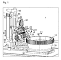
- Fig . 1 shows a side view of the chamfering and deburring device 30 according to the invention installed in a gear cutting machine 1 according to the prior art.
- a workpiece 10 On a machine table 50, a workpiece 10 is clamped over a workpiece clamping 55.
- a machining head 20 for receiving a tool 25, for example a hob, is mounted for vertical movement on a machine stand 60. About the feed axis-X1 the machine stand with the machining head for producing a toothing in the direction of the workpiece 10 is delivered.
- the cutting carriage 61 is moved with the machining head 20 for generating teeth from bottom to top with the Z1-axis and thus generated with the hob 25, which is driven by the motors 22 about the B1 axis, the teeth.
- the generation of the toothing takes place in a roller-coupled manner, ie the milling cutter rotation (B1) and milling movement in the Z1 direction takes place as a function of the rotational position of the workpiece 10 or of the machine table 50 about the C1 axis.
- the milling carriage is moved by means of the drive motor 65 and the ball screw 66.
- the pivot angle of the machining head is set to the tool pitch angle and the helix angle of the toothing via the A1 axis with the axis motor 67.
- These axes also serve as adjustment axes for chamfering and deburring device 30 at the same time.
- the chamfering and deburring device is still mounted on a separate infeed axis 32, X3-axis. This design does not require the entire stand weight to be moved in the X1 direction to move the deburring tool or chamfering and deburring device radially toward the workpiece.
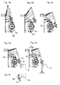
- an exemplary chamfering and deburring device 30 is shown pivoted to its machining position.
- the chamfering and deburring device is pivoted via a multi-joint arrangement by the actuator 31, in this case a pneumatic cylinder, which pivots the chamfering and deburring device from its parking position on top of the machining head 20 into the working position.
- this actuator could also be an NC axis.
- the Anfasfräser 35 clamped in the engaging spindle 34 and the tool holders 36 machined the tooth edge of the workpiece 10.
- the gripping spindle 34 can be pivoted about the A3 axis via the pivoting gear 37 with the drive motor 33.
- the Anfasfräser 35 can be pivoted in its inclination relative to the tooth edge, which then can be done adjusting the chamfer angle of the chamfer.
- the movement of the chamfering and deburring device 30 takes place in dependence on the table position.
- Fig. 3a to 3c show the pivoting movement of the chamfering and deburring device 30 from its parking position Fig. 3a to her working position Fig. 3c , About this pivotal movement, the engaging spindle 34 is brought into engagement with the tool 35 and the workpiece 10.
- the measuring device 43 is shown, with a measuring head 42 and a probe 41 with which the tooth shape scans and so the contour of the tooth edge can be determined in preparation for chamfering.
- Fig. 3d to 3f The chamfering and deburring device is shown schematically when machining a tooth contour.
- the radial feed of the tool to the workpiece and the movement in the direction of the tooth height take place via the feed carriage 32.
- the maximum workable tooth height (h) depends directly on the maximum delivery in X3 direction (hx).
- Fig. 3e shows the maximum possible delivery via the X3-axis. If larger tooth heights are required in this case, alternatively or additionally, a movement must be made via the X1 axis.
- the Fig. 3f shows the gripping spindle 34 in the processing of the lower end face of a toothing on the workpiece 10.
- the gripping spindle 34 was pivoted in this view by 180 ° with the pivot motor 33 upwards.
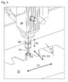
- the Fig. 4 is a detail view in which the gripping spindle 34 is shown with the Anfasfräser 35 at the processing station.
- the cutter follows the tooth edge contour by moving it radially across the X3 / X1 axis in the direction of tooth height as the workpiece rotates about its C1 axis. Due to the combination of X and C movement, the cutter follows in the 2D surface of the toothing.
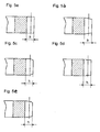
- stirbene gearing as in the Fig. 5a be shown, startable.
- the end faces in the region of the toothing are formed as in the sketches in the Fig. 5b to 5d is drawn, in addition, a controlled vertical movement in the Z1 direction (shown in phantom) must be made depending on the tooth height h.
- a movement around the A3 axis can also be made to match the chamfer size between the right and left flanks.
Abstract
Die Erfindung betrifft ein Verfahren und eine Vorrichtung zum Anfasen und Entgraten verzahnter, vorzugsweise großvolumiger, Werkstücke mit einer Entgratvorrichtung die auf oder an dem Bearbeitungskopf einer Verzahnmaschine angeordnet ist und die zumindest teilweise die Maschinenachsen der Verzahnmaschine nutzt, um eine Verzahnung entlang einer Zahnkontur anzufasen und zu entgraten.The invention relates to a method and a device for chamfering and deburring toothed, preferably large-volume workpieces with a deburring device which is arranged on or at the machining head of a gear cutting machine and which at least partially uses the machine axes of the gear cutting machine to chamfer and to secure toothing along a tooth contour deburring.
Description
Die Erfindung betrifft ein Verfahren und eine Vorrichtung zum Anfasen und Entgraten verzahnter, vorzugsweise großvolumiger Werkstücke mit einer Anfas- und Entgratvorrichtung, die auf oder an dem Bearbeitungskopf einer Verzahnmaschine angeordnet ist und die zumindest teilweise die Maschinenachsen der Verzahnmaschine nutzt, um eine Verzahnung entlang einer Zahnkontur anzufasen und zu entgraten.The invention relates to a method and a device for chamfering and deburring toothed, preferably large-volume workpieces with a chamfering and deburring device, which is arranged on or on the machining head of a gear cutting machine and which at least partially uses the machine axes of the gear cutting machine, around a toothing along a tooth contour to chamfer and deburr.
Bei der spanenden Bearbeitung von metallischen Werkstücken kommt es insbesondere an der Werkzeugaustrittsseite zur Bildung von Graten. Diese groben Grate müssen vor der Weiterbehandlung der Werkstücke entfernt werden, damit es nicht zu Störungen in den Folgeprozessen oder zur Verletzung der Maschinenbediener kommen kann. Zusätzlich werden vor einem Wärmebehandlungsprozess häufig die Stirnkante von Verzahnungen mit einer Schutzfase versehen, die die Zahnkanten des Werkstücks vor Beschädigungen und Aufwürfen schützen soll und vor allem um das Hartfeinbearbeitungswerkzeug im Folgeprozess vor stark aufgekohlten harten Kanten und Graten zu schützen. Der Begriff Entgraten wird dabei häufig synonym für Entgraten und Anfasen verwendet. Wobei man unter Entgraten das Entfernen des groben Grates, der nach einem Zerspanungsprozess am Werkstück anhaftet, versteht und unter Anfasen das gezielte Anbringen einer Schutzfase, wobei je nach Verfahren dabei auch gleichzeitig der Grobgrat mit entfernt werden kann.During the machining of metallic workpieces, burrs are formed, in particular on the tool exit side. These coarse burrs must be removed before further processing of the workpieces, so that disturbances in the subsequent processes or injury to the machine operator can not occur. In addition, before a heat treatment process often the front edge of gears are provided with a protective chamfer to protect the tooth edges of the workpiece from damage and thinning and especially to protect the hard finishing tool in the subsequent process of heavily carburized hard edges and burrs. The term deburring is often used synonymously for deburring and chamfering. By deburring the removal of the coarse burr that adheres to the workpiece after a cutting process, understands and chamfering the targeted attachment of a Schutzfase, which can also be removed depending on the process while the coarse burr.
Bei der Großserienfertigung von verzahnten Werkstücken mit Durchmessern kleiner ca. 500 mm gehört ein Anfasen und Entgraten von verzahnten Werkstücken in einer Verzahnmaschine inzwischen zum Stand der Technik. Die gängigsten Verfahren hierzu sind Drück-/Wälzentgraten (
Bei Großverzahnungen (Werkstückdurchmesser >1000 mm bis >16.000 mm), großen Moduln und tonnenschweren Werkstücken werden die verzahnten Werkstücke heute häufig noch mit handgeführten Entgratwerkzeugen, beispielsweise Einhandschleifgeräten, bearbeitet. Je größer der Werkstückdurchmesser und je größer der Modul ist, umso wahrscheinlicher ist eine manuelle Entgratbearbeitung, insbesondere wenn es sich um kleine Werkstück-Losgrößen handelt, für die die Beschaffung eines speziell angepassten Entgratwerkzeuges, wie z.B. eines ChamferCut-Fräsers, unwirtschaftlich ist.In the case of large gears (workpiece diameter> 1000 mm to> 16,000 mm), large modules and workpieces weighing several tons, today the toothed workpieces are often still processed with hand-held deburring tools, for example single-handed grinding tools. The larger the workpiece diameter and the larger the modulus, the more likely a manual deburring operation, especially if it is small workpiece lot sizes, for which the procurement of a specially adapted deburring tool, such. a Chamfer Cut router, is uneconomical.
Bei neuerer Prozessauslegung geht der Trend weg vom Anfasen mit handgeführten Entgratwerkzeugen. Dafür gibt es verschiedene Gründe.
- Die Anforderungen an die Verzahnungsqualität steigt bei manchen Verzahnungen deutlich an. So wird bei hochbelasteten Verzahnungen, beispielsweise für Windenergiegetriebe, immer mehr auch Reproduzierbarkeit für Fasengröße und Fasenwinkel an allen Zähnen und Werkstücken sowie auf die Fasenqualität geachtet.
- Der Schwerpunkt bei der Bearbeitung dieser Werkstücke liegt nicht mehr nur auf der reinen Bearbeitungszeit, sondern es ist wichtiger ein möglichst fertig bearbeitetes Werkstück von der Maschine zu erhalten.
- Aus Gründen der Arbeitssicherheit sind die mit hoher Geräusch- und Staubemission belasteten Handarbeitsplätze in einer modernen Fertigungshalle nicht mehr gewünscht.
- Rohlinge und erst recht verzahnte Werkstücke bei Großverzahnungen sind teilweise teuer bis sehr teuer. Sollte ein Zahnrad beim Handling nachhaltig geschädigt werden gibt es teils sehr lange Wiederbeschaffungszeiten bis wieder ein verzahnbarer Rohling vorliegt. Von daher wird auch hier versucht durch die Integration von zusätzlichen Prozessen in die Verzahnmaschine ein möglichst fertiges Werkstück von der Maschine zu nehmen.
- Es gibt Werkstücke, bei denen die Stirnseiten der Verzahnungen nicht eben sind sondern Schrägen, Radien oder Absätze aufweisen. In diesem Fall wird, insbesondere bei Schrägverzahnung, die Anbringung einer gleichmäßigen Fase mit handgeführten Entgratwerkzeugen sehr schwierig.
- The demands on the quality of the teeth increase significantly in some gears. Thus, with highly loaded gears, for example for wind energy gear, more and more reproducibility for bevel size and chamfer angle on all teeth and workpieces and on the chamfer quality is respected.
- The focus in the machining of these workpieces is no longer just on the pure machining time, but it is more important to get as finished as possible machined workpiece from the machine.
- For reasons of safety at work, the manual workstations with high noise and dust emissions are no longer desired in a modern production hall.
- Blanks and evenly toothed workpieces with large gears are sometimes expensive to very expensive. If a gear is sustainably damaged during handling, there are sometimes very long replacement times until a toothed blank is available again. Therefore, it is also attempted here by the integration of additional processes in the gear cutting machine to take as finished a workpiece from the machine.
- There are workpieces in which the faces of the teeth are not flat but have slopes, radii or heels. In this case, the attachment of a uniform bevel with hand-held deburring tools becomes very difficult, especially with helical teeth.
Diese Gründe sprechen auch bei Großverzahnungen für eine automatisierte Erzeugung der Fasen an den Stirnkanten der Verzahnungen. Dabei muss das Verfahren eine kostengünstige Lösung bieten und auf Grund der geringen Werkstück-Losgrößen müssen möglichst unterschiedliche Verzahnungen bearbeitbar sein. Außerdem soll die Gefahr, dass das Werkstück beim Transport oder beim Anfasen beschädigt wird, minimiert werden.These reasons are also in large gears for automated production of chamfers on the front edges of the teeth. The process must offer a cost-effective solution and due to the small workpiece lot sizes as different teeth must be editable. In addition, the risk of the workpiece being damaged during transport or chamfering should be minimized.
Daher scheiden separate Entgratmaschinen, die heute auch für Großverzahnungen (< 3500 mm Durchmesser) verfügbar sind, aus. Diese Entgratmaschinen arbeiten häufig mit einem System bei dem der Fräser auf der Zahnkante aufliegt und so der Zahnkante folgt (System Gratomat). Nachteilig an diesem System ist es, dass der Fasenwinkel und die Fasengröße über der Zahnhöhe stark unterschiedlich ist.Therefore, separate deburring machines, which are also available today for large gearings (<3500 mm diameter), are ruled out. These deburring machines often work with a system in which the milling cutter rests on the tooth edge and thus follows the tooth edge (Gratomat system). A disadvantage of this system is that the chamfer angle and the chamfer size over the tooth height is very different.
Ein weiteres System arbeitet mit einem Frässtift, der über eine Hilfseinrichtung geführt der Zahnkontur nachfolgt. Die eigenständige Entgratmaschine nach der
Die
Die
Aufgabe der vorliegenden Erfindung ist es nun ein Entgratverfahren und eine kostengünstige Anfas- und Entgratvorrichtung zu schaffen, mit der ein Anfasen und Entgraten, vorzugweise von Großverzahnungen, auf einer Verzahnmaschine stattfinden kann. Das Werkstück soll anschließend fertig angefast und entgraten von der Maschine abgespannt werden können.The object of the present invention is now to provide a deburring method and a cost-effective chamfering and deburring device, with which chamfering and deburring, preferably of large gears, can take place on a gear cutting machine. The workpiece should then be ready chamfered and deburred by the machine can be braced.
Erfindungsgemäß wird diese Aufgabe durch eine Vorrichtung mit den Merkmalen des Anspruchs 1 gelöst.According to the invention this object is achieved by a device having the features of
Weiterbildungen der Erfindung sind in den Unteransprüchen zu entnehmen.Further developments of the invention can be found in the dependent claims.
Die erfindungsgemäße Vorrichtung ist auf oder am Bearbeitungskopf einer Verzahnmaschine montiert. Dies bietet den Vorteil, dass die Maschinenachsen, die zunächst zur Verzahnungserzeugung an einem Werkstück genutzt werden, auch für die Anfasbearbeitung zumindest teilweise genutzt oder sogar vollständig genutzt werden können.The device according to the invention is mounted on or on the machining head of a gear cutting machine. This offers the advantage that the machine axes, which are initially used for gear production on a workpiece, also for the Chamfering can be at least partially used or even fully utilized.
So wird zur Durchführung des erfindungsgemäßen Verfahren die Anfas- und Entgratvorrichtung nach Abschluss der Verzahnungsbearbeitung aus ihrer Ruheposition in ihre Arbeitsposition gefahren oder geschwenkt und anschließend wird die Anfasbearbeitung begonnen. Die Ruheposition der Entgratvorrichtung befindet sich dabei vorzugsweise auf dem Bearbeitungskopf oberhalb der Werkzeugaufnahme für den Wälz- oder Profilfräser zur Verzahnungserzeugung. Dort stört sie am wenigsten bei den Verfahrbewegungen des Fräskopfes zur Zahnradbearbeitung und die Gefahr von Kollisionen mit dem Werkstück oder der Vorrichtung zur Werkstückaufspannung ist bei der Verzahnungserzeugung am geringsten. Andererseits ist sie dort sehr nahe an der Bearbeitungsstelle zur Verzahnungsbearbeitung angebracht und ist somit durch einfache Verfahrbewegungen leicht in den Eingriff mit der Verzahnung zu bringen. Die Zustellung des Entgratfräsers zum verzahnten Werkstück erfolgt dabei in einer Ebene, die sich parallel zur X-Achse/Z-Achse und zur Mittelachse des Maschinentisches erstreckt. In der Arbeitsstellung befindet sich die Entgratspindel zwischen Verzahnwerkzeug und Werkstück, zumindest aber vor dem Verzahnwerkzeug. Damit kann die Entgratvorrichtung eingesetzt werden, ohne dass das Verzahnwerkzeug erst aus der Maschine ausgebaut werden muss. Dies bedeutet auch, das der Verzahnherstellungs- und Anfasprozess automatisch gesteuert nacheinander erfolgen kann und ein fertig bearbeitetes Werkstück aus der Maschine kommt. Weiter wäre es möglich zwischen mehreren Frässchritten eine Anfas- und Entgratbearbeitung durchzuführen. Dies wäre bei einem notwendigen Ausbau des Verzahnungsfräswerkzeuges nicht möglich.Thus, in order to carry out the method according to the invention, the chamfering and deburring device is moved or pivoted from its rest position into its working position after completing the toothing machining, and then the chamfering machining is started. The rest position of the deburring device is preferably located on the machining head above the tool holder for the rolling or profile cutter for gear generation. There it disturbs the least during the movements of the milling head for gear processing and the risk of collisions with the workpiece or the device for workpiece clamping is the lowest in the gear production. On the other hand, it is mounted there very close to the processing point for gear processing and is thus easy to bring by simple movement movements in engagement with the teeth. The delivery of the deburring cutter to the toothed workpiece takes place in a plane which extends parallel to the X-axis / Z-axis and to the central axis of the machine table. In the working position, the deburring spindle is located between the gear cutting tool and the workpiece, but at least before the gear cutting tool. Thus, the deburring device can be used without the gear tool must first be removed from the machine. This also means that the Verzahnherstellungs- and Anfasprozess can be done automatically controlled in succession and a finished machined workpiece comes from the machine. It would also be possible to perform a chamfering and deburring process between several milling steps. This would not be possible with a necessary expansion of the Verzahnungsfräswerkzeuges.
Das Anfaswerkzeug, beispielsweise ein kegeliger oder zylindrischer Frässtift, wird dabei über Achsbewegungen des Bearbeitungskopfes mit seiner Anfas- und Entgratvorrichtung entlang der Zahnkante einer Verzahnung geführt, während sich das Werkstück mit einer vorgegebenen Geschwindigkeit um seine Mittelachse dreht. In einem ersten Schritt wird zunächst die Fase an einer Stirnseite, beispielsweise der Oberseite, einer Verzahnung gefräst. Im Anschluss daran wird das Werkzeug auf die gegenüberliegende Stirnseite der Verzahnung zugestellt und in einem zweiten Schritt auch diese Stirnseite mit einer Anfasung versehen. Über die Schwenkeinrichtung für die Anfasspindel kann deren Einschwenkwinkel beispielsweise gesteuert über der Zahnhöhe und in Abhängigkeit von der Flanke geändert werden. So kann auf der rechten und linken Flanke und bedarfsweise auch am Zahnfuß und Zahnkopf eine unterschiedliche Fase erzeugt werden.The chamfering tool, for example a conical or cylindrical burr, is thereby guided over axis movements of the machining head with its chamfering and deburring device along the tooth edge of a toothing, while the workpiece rotates about its central axis at a predetermined speed. In a first step, the bevel is first milled on a front side, for example the top side, of a toothing. Following this, the tool is delivered to the opposite end of the toothing and provided in a second step, this end face with a chamfer. About the pivoting device for the Angriffpindel their Einschwenkwinkel can be changed, for example, controlled by the tooth height and in dependence on the edge. Thus, a different bevel can be generated on the right and left flank and, if necessary, also on the tooth base and tooth tip.
Parameter wie beispielsweise Fasengröße, Fasenwinkel, Fasenverlauf können programmtechnisch in einem Bearbeitungsprogramm in der Maschinensteuerung hinterlegt und durch die NC-Achsen eingestellt werden. Über die Vorschubwerte oder die Anzahl der Schnitte kann dann beispielsweise auch die Fasengröße beeinflusst werden. Durch das NC-Programm gesteuert können diese Fasenparameter an einer Vielzahl an Werkstücken reproduzierbar erzeugt werden.Parameters such as chamfer size, chamfer angle, chamfering can be programmed in a machining program in the machine control and set by the NC axes. By way of example, the chamfer size can also be influenced via the feed values or the number of cuts. Controlled by the NC program, these bevel parameters can be generated reproducibly on a large number of workpieces.
In einer alternativen Ausführungsform ist die Anfas- und Entgratvorrichtung noch zusätzlich auf einer weiteren Zustellachse montiert, die sich in Radial-Richtung auf das Werkstück zu erstreckt. Durch die geringere zu bewegende Masse, nämlich nur noch die Anfas- und Entgratvorrichtung an der Stelle des den komplette Maschinenständers, ist eine dynamischere Bewegung in X-Richtung (Zustellrichtung der Zahnhöhe) ermöglicht. Damit können insgesamt höhere Achsgeschwindigkeiten bei allen genutzten Achsen gefahren werden. Dies ist besonders bei der Anfasbearbeitung im Bereich der Zahnflanken von Vorteil, da hier die größten Änderungen der radialen Zustellung je Winkelgrad am Werkstück erforderlich sind. Im Bereich von Zahnkopf und Zahnfuß hingegen sind nur geringe radiale Zustellungen je Winkelgrad am Werkstück erforderlich.In an alternative embodiment, the chamfering and deburring device is additionally mounted on a further feed axis, which extends in the radial direction toward the workpiece. Due to the lower mass to be moved, namely only the chamfering and deburring at the point of the complete machine stand, a more dynamic movement in the X direction (feed direction of the tooth height) is possible. As a result, overall higher axis speeds can be used for all axes used. This is particularly advantageous for chamfering in the area of the tooth flanks, since here the greatest changes in the radial delivery per angular degree on the workpiece are required. In the area of the tooth head and tooth root, on the other hand, only slight radial infeeds are required per angular degree on the workpiece.
Weiterhin wäre es durch eine zusätzliche NC-Achse an der Entgratvorrichtung möglich, Bewegungen parallel zur X-Z-Ebene entlang der Stirnseite der Verzahnung mit höherer Geschwindigkeit zu fahren, da sich die bewegte Masse nur noch aus Teilen der Entgratvorrichtung sowie dem Antrieb für das Entgratwerkzeug zusammensetzt, so dass nicht mehr der gesamte Fräskopf in Vertikal-Richtung (Z-Achse) bewegt werden muss. Durch diese verschiedenen möglichen Ausführungsformen lässt sich die Entgratvorrichtung je nach den geforderten Leistungsdaten unterschiedlich konfigurieren.Furthermore, it would be possible by an additional NC axis on the deburring device to move movements parallel to the XZ plane along the front side of the toothing with higher speed, since the moving mass is composed only of parts of the deburring and the drive for the deburring tool, so that no longer the entire milling head in the vertical direction (Z-axis) must be moved. Through these various possible embodiments, the deburring device can be configured differently depending on the required performance data.
In einer weiteren Ausführungsform kann in der Maschine oder am Bearbeitungskopf der Maschine ein Mess-System angeordnet sein, mit dem Messaufgaben an der Verzahnung durchgeführt werden können. Dies kann dazu dienen, die verzahnte Qualität zu bestimmen und zu dokumentieren, aber auch um die Verzahnung positioniert zu einem bestimmten Punkt zu erzeugen. Diese Messeinrichtung kann erfindungsgemäß nun auch dazu genutzt werden, die Lage der Verzahnung und die Zahnform am Werkstück zu bestimmen und ggf. auch den Verlauf der Stirnseite im Bereich der Verzahnung zu ermitteln. Damit muss diese Zahnkontur nicht aufwändig programmiert werden, sondern kann durch eine einfache Vermessung, z.B. einer einzelnen Zahnlücke und der Stirnseite im Bereich der Verzahnung, von der Maschinensteuerung berechnet werden. Dabei reicht es aus, wenn nur ein Zahn oder eine Zahnlücke vermessen wurde. Denn die restliche Verzahnkontur kann mit Verzahndaten, wie z.B. der Zähnezahl, der Zahnbreite, dem Schrägungswinkel der Verzahnung und andere Verzahndaten, berechnet werden. Diese sind bereits von der Verzahnungserzeugung bekannt und können in die Berechnung mit einfließen. Daraus kann die Steuerung dann ein Programm für die Anfasbearbeitung der gesamten Verzahnung erstellen. Dieses Verfahren kann bei evolventischen und nicht-evolventischen Verzahnungen angewendet werden. Denn besonders bei nicht-evolventischen Verzahnungen ist die Bestimmung des Flankenverlaufs nicht trivial.In a further embodiment, a measuring system can be arranged in the machine or at the machining head of the machine, with which measuring tasks on the toothing can be performed. This can serve to determine and document the interlocked quality, but also to create the interlocking positioned at a particular point. This measuring device according to the invention can now also be used to determine the position of the toothing and the tooth shape on the workpiece and possibly also to determine the course of the front side in the region of the toothing. Thus, this tooth contour does not have to be programmed consuming, but can by a simple measurement, for example, a single tooth gap and the front side in the region of the toothing, be calculated by the machine control. It is sufficient if only one tooth or a tooth gap was measured. Because the remaining Verzahnkontur can be calculated with Verzahndaten, such as the number of teeth, the tooth width, the helix angle of the teeth and other gear data. These are already known from gear generation and can be included in the calculation. From this, the controller can then create a program for chamfering the entire gearing. This procedure can be applied to involute and non-involute gears. Especially for non-involute gears, the determination of the edge profile is not trivial.
Ebenso wäre es möglich, nur Teilbereich eines einzelnen Zahnes oder einer Zahnlücke, wie z.B. den Zahnfuß und Zahnkopfbereich, mit der Messeinrichtung abzutasten, da der Verlauf der Zahnflanke, besonders bei evolventischen Verzahnungen bereits von der Verzahnungsbearbeitung bekannt ist. So kommt man sehr einfach und schnell zu einem Anfasprogramm ohne dass ein großer Programmieraufwand notwendig wäre.Likewise, it would be possible to use only a portion of a single tooth or a tooth space, e.g. the tooth root and tooth tip area, with the measuring device to sense, since the course of the tooth flank, especially in involute gears already known from the teeth machining. So you get very easy and fast to a Anfasprogramm without a large programming effort would be necessary.
Eine weitere Möglichkeit für die Programmierung der Fasenform besteht in einer, vorzugsweise benutzergeführten, "Teach-In"-Methode. Durch manuelles Anfahren von vorgegebenen Punkten mit einem am Bearbeitungskopf angebrachten Taster können vorgegebene Referenzpunkte an einer Zahnlücke bestimmt werden. Daraus kann die Maschinensteuerung dann anschließend zusammen mit den der Steuerung bekannten Verzahndaten das Bearbeitungsprogramm auch für die restlichen Lücken erstellen. Wichtig sind dabei vor allem mehrere Referenzpunkte im Bereich des Zahnkopf- und Zahnfußradius. Die Lage der Evolvente entlang der Zahnflanke ist durch den vorhergehenden Verzahnprozess weitestgehend bekannt.Another possibility for programming the bevel shape is a, preferably user-guided, "teach-in" method. By manually approaching predetermined points with a button attached to the machining head, predetermined reference points on a tooth gap can be determined. From this, the machine control can then subsequently create the machining program for the remaining gaps together with the gear data known to the controller. Above all, several reference points in the area of the tooth tip and tooth root radius are important. The position of the involute along the tooth flank is largely known from the previous toothing process.
In einer weiteren alternativen Ausführungsform kann die Anfas- und Entgratvorrichtung auch für weitere Bearbeitungsoperationen am Werkstück, wie z.B. Fräs-, Bohr- oder Schleifoperationen, genutzt werden. Über einen ggf. automatisieren Werkzeug- oder Bearbeitungskopfwechsel an der Anfas- und Entgratvorrichtung können auch verschiedene Bearbeitungsoperationen nacheinander ausgeführt werden.In a further alternative embodiment, the chamfering and deburring device may also be used for further machining operations on the workpiece, such as e.g. Milling, drilling or grinding operations can be used. By means of a possibly automated tool or machining head change on the chamfering and deburring device, it is also possible to carry out various machining operations one after the other.
Weitere Merkmale, Einzelheiten und Vorteile der Erfindung werden anhand von in der Zeichnung dargestellten Ausführungsbeispiele näher erläutert. Es zeigen:
- Fig. 1
- eine Verzahnmaschine mit der erfindungsgemäßen Anfas- und Entgratvorrichtung;
- Fig. 2
- eine Ansicht der Anfas- und Entgratvorrichtung aus
Fig. 1 ; - Fig. 3a-c
- eine schematische Darstellung der Bewegung der Anfas- und Entgratvorrichtung von ihrer Parkposition in die Arbeitsposition;
- Fig. 3d-e
- eine schematische Darstellung der Arbeitsbewegungen der Anfasspindel;
- Fig. 3f
- eine Detailansicht der Anfas- und Entgratvorrichtung bei der Bearbeitung der Unterseite eines verzahnten Werkstücks;
- Fig. 4
- eine Detailansicht der Anfas- und Entgratvorrichtung aus
Fig. 1 mit dem Entgratwerkzeug im Bearbeitungseingriff; und - Fig. 5a-e
- eine schematische Darstellung verschiedener verzahnter Werkstücke mit unterschiedlichen Stirnseiten im Bereich der Verzahnung.
- Fig . 1
- a gear cutting machine with the chamfering and deburring device according to the invention;
- Fig . 2
- a view of the chamfering and deburring device
Fig. 1 ; - Fig . 3a-c
- a schematic representation of the movement of the chamfering and deburring device from its parking position to the working position;
- Fig . 3d-e
- a schematic representation of the working movements of the engaging spindle;
- Fig . 3f
- a detailed view of the chamfering and deburring during machining of the underside of a toothed workpiece;
- Fig . 4
- a detailed view of chamfering and deburring from
Fig. 1 with the deburring tool in machining engagement; and - Fig . 5a-e
- a schematic representation of various toothed workpieces with different end faces in the region of the toothing.
Bewegt wird der Frässchlitten über den Antriebsmotor 65 und die Kugelrollspindel 66. Über die A1-Achse mit dem Achsmotor 67 wird der Schwenkwinkel des Bearbeitungskopfs auf den Werkzeugsteigungswinkel und den Schrägungswinkel der Verzahnung eingestellt. Diese Achsen dienen auch gleichzeitig als Einstellachsen für die Anfas- und Entgratvorrichtung 30. Zusätzlich ist bei dieser Ausführung die Anfas- und Entgratvorrichtung noch auf einer separaten Zustellachse 32, X3-Achse, montiert. Durch diese Ausführung muss nicht das gesamte Ständergewicht in X1-Richtung bewegt werden, um das Entgratwerkzeug bzw. die Anfas- und Entgratvorrichtung radial in Richtung auf das Werkstück zu bewegen.The milling carriage is moved by means of the
In der Detailansicht
In der
Die
Die
Claims (10)
dadurch gekennzeichnet,
dass die Anfasspindel mit dem Anfasfräser zur Anfasbearbeitung von einer Ruheposition außerhalb der Störkontur der Verzahnungsbearbeitung in eine Arbeitsposition im Arbeitsbereich des Verzahnwerkzeugs durch die Anfas- und Entgratvorrichtung geschwenkt und/oder zugestellt wird, wobei die Anfasspindel mit dem Anfasfräser näher am Werkstück als der Verzahnungsfräser positioniert wird, sodass das Verzahnwerkzeug bei der Anfasbearbeitung im Bearbeitungskopf verbleiben kann und wobei die Bewegungen der Anfasspindel mit dem Anfasfräser zur Konturverfolgung entlang der Zahnkante durch die Bewegungsachsen der Verzahnmaschine, vorzugsweise die des Bearbeitungskopfs, erfolgen.Method for chamfering and deburring toothed workpieces, in particular large-volume workpieces, with a chamfering and deburring device, which is arranged on or at the machining head of a gear cutting machine,
characterized,
is that the Anfasspindel pivoted with the Anfasfräser to chamfering from a rest position outside the interference contour of the tooth-machining to a work position in the work area of the Verzahnwerkzeugs by the chamfering and deburring device and / or delivered, said Anfasspindel is positioned with the Anfasfräser closer to the workpiece than the toothed cutter so that the gear tool can remain in the machining head during chamfering and wherein the movements of the engaging spindle with the Anfasfräser for contour tracking along the tooth edge by the axes of movement of the gear cutting machine, preferably those of the machining head done.
Applications Claiming Priority (1)
| Application Number | Priority Date | Filing Date | Title |
|---|---|---|---|
| DE102014014132.2A DE102014014132A1 (en) | 2014-09-30 | 2014-09-30 | Method and device for chamfering and deburring toothed workpieces |
Publications (1)
| Publication Number | Publication Date |
|---|---|
| EP3012056A1 true EP3012056A1 (en) | 2016-04-27 |
Family
ID=54010942
Family Applications (1)
| Application Number | Title | Priority Date | Filing Date |
|---|---|---|---|
| EP15182503.1A Withdrawn EP3012056A1 (en) | 2014-09-30 | 2015-08-26 | Method and device for chamfering and deburring toothed workpieces |
Country Status (4)
| Country | Link |
|---|---|
| US (1) | US9993887B2 (en) |
| EP (1) | EP3012056A1 (en) |
| CN (1) | CN105458412A (en) |
| DE (1) | DE102014014132A1 (en) |
Cited By (4)
| Publication number | Priority date | Publication date | Assignee | Title |
|---|---|---|---|---|
| EP3412393A3 (en) * | 2017-06-06 | 2019-03-13 | Liebherr-Verzahntechnik GmbH | Device and method for chamfering an internally cogged workpiece |
| EP3552743A1 (en) * | 2018-04-11 | 2019-10-16 | Liebherr-Verzahntechnik GmbH | Device and method for chamfering of a toothed workpiece |
| EP3552744A1 (en) * | 2018-04-11 | 2019-10-16 | Liebherr-Verzahntechnik GmbH | Device and method for finishing a workpiece |
| US10688575B2 (en) | 2017-06-06 | 2020-06-23 | Liebherr-Verzahntechnik Gmbh | Apparatus and method for chamfering a workpiece with internal gearing |
Families Citing this family (16)
| Publication number | Priority date | Publication date | Assignee | Title |
|---|---|---|---|---|
| CN106064259B (en) * | 2016-08-19 | 2018-01-12 | 浙江振兴阿祥集团有限公司 | Gear-hobbing machine hob head |
| DE102017000072A1 (en) * | 2017-01-05 | 2018-07-05 | Liebherr-Verzahntechnik Gmbh | Method for automatically determining the geometric dimensions of a tool in a gear cutting machine |
| DE102017003648A1 (en) | 2017-04-13 | 2018-10-18 | Liebherr-Verzahntechnik Gmbh | Method for tooth machining a workpiece |
| EP3517235B1 (en) * | 2018-01-25 | 2020-12-09 | Klingelnberg GmbH | Method for deburring bevel wheels and cnc machine with a corresponding software for deburring |
| DE102018108635A1 (en) * | 2018-04-11 | 2019-10-17 | Klingelnberg Gmbh | METHOD FOR DEBURRING BRUSHES OF GEARS |
| WO2020031377A1 (en) | 2018-08-10 | 2020-02-13 | ヤマザキマザック株式会社 | Gear phase detection method, gear production method, workpiece edge position detection method, and gear phase-detecting machine tool |
| DE102018126699B4 (en) * | 2018-10-25 | 2020-10-15 | Volkswagen Aktiengesellschaft | Process for the production of spur gear toothed workpieces as well as spur gear toothed workpiece |
| DE102019131266A1 (en) * | 2019-11-20 | 2021-05-20 | Schaeffler Technologies AG & Co. KG | Method and device for deburring an internally toothed workpiece |
| CN111112687B (en) * | 2020-02-20 | 2021-06-11 | 杨利人 | Gear wall drilling device |
| DE102020004346A1 (en) | 2020-07-20 | 2022-01-20 | Gleason-Pfauter Maschinenfabrik Gmbh | Process for gear processing |
| JP7193677B2 (en) * | 2020-10-22 | 2022-12-20 | 住友電気工業株式会社 | Manufacturing method of sintered gear |
| CN112427746A (en) * | 2020-11-12 | 2021-03-02 | 苏州哈勒智能制造有限公司 | Gear tooth shape chamfering equipment and machining mode thereof |
| CN112452628A (en) * | 2020-11-17 | 2021-03-09 | 重庆优多齿轮制造有限公司 | Gear nursing device and method |
| CN113001185B (en) * | 2021-03-05 | 2024-04-12 | 秦川集团(西安)技术研究院有限公司 | Shaft tooth composite machining device |
| CN113263228A (en) * | 2021-06-07 | 2021-08-17 | 浙江陀曼精密机械有限公司 | Rolling-over multi-path composite machining device |
| CN117324700B (en) * | 2023-12-01 | 2024-04-09 | 江苏盛日机械设备制造有限公司 | Gear roller repairing and slotting device of shaft furnace |
Citations (13)
| Publication number | Priority date | Publication date | Assignee | Title |
|---|---|---|---|---|
| DE1969872U (en) | 1967-05-31 | 1967-10-05 | Rausch K G Maschf | MACHINE FOR DEBURRING THE HEAD EDGES OF GEARS. |
| DE2534574A1 (en) | 1975-08-02 | 1977-02-10 | Hurth Masch Zahnrad Carl | Geat tooth edge nibbler - uses toothed cutter wheel engaged with gear and with notched flanks on cutter teeth |
| DE4019834A1 (en) * | 1990-06-21 | 1992-01-02 | Siemens Ag | Automatically controlling milling of gearwheels - using movable optic sensor to identify each gearwheel before processing |
| DE202004008263U1 (en) * | 2004-05-19 | 2004-08-12 | Klingelnberg Gmbh | Deburring knife, device for receiving deburring knives and bevel gear cutting machine for gripping and / or deburring a bevel gear |
| DE202005011790U1 (en) * | 2005-07-22 | 2005-10-20 | Gleason-Pfauter Maschinenfabrik Gmbh | Unit for deburring and creation of chamfer at teeth of bevel wheel, attached to main device for creation of toothed areas |
| DE202005014619U1 (en) | 2005-09-13 | 2005-12-29 | Fette Gmbh | Tool arrangement for producing beveled gearing of spur gear has rough hobbing cutter, trimming cutter and plane hobbing cutter fixed relative to each other, in specified rotating position, on mandrel and gearing of plane cutter has section |
| DE10330474B4 (en) * | 2003-07-05 | 2009-03-05 | Fette Gmbh | Device for producing a gear from a gear blank |
| DE102009019433A1 (en) | 2009-04-29 | 2010-11-04 | Gleason-Pfauter Maschinenfabrik Gmbh | Method and device for machining the tooth edges of spur-toothed work wheels |
| DE112008003992T5 (en) | 2008-09-01 | 2011-07-21 | Senjo Seiki Co., Ltd., Shizuoka | processing device |
| US20120230791A1 (en) * | 2009-12-22 | 2012-09-13 | The Gleason Works | Method and apparatus for manufacturing bevel gears |
| DE202012008601U1 (en) | 2012-09-10 | 2012-12-12 | Klingelnberg Gmbh | Machine tool with chamfering and / or deburring device |
| US20130121779A1 (en) * | 2011-11-11 | 2013-05-16 | Liebherr-Verzahntechnik Gmbh | Method and device for machining tooth edges |
| DE202013009805U1 (en) * | 2013-03-28 | 2014-01-10 | Liebherr-Verzahntechnik Gmbh | Device for chamfering a workpiece |
Family Cites Families (6)
| Publication number | Priority date | Publication date | Assignee | Title |
|---|---|---|---|---|
| DE19928500B4 (en) * | 1999-06-22 | 2014-04-24 | Reishauer Ag | Method and device for the automatic measurement of process and workpiece characteristics when grinding gears |
| DE10211129A1 (en) * | 2002-02-22 | 2003-10-16 | Zahnradfabrik Friedrichshafen | Device facilitating conduction of all steps required in production of meshing edges of workpieces |
| ATE424960T1 (en) * | 2006-06-06 | 2009-03-15 | Klingelnberg Gmbh | APPARATUS AND METHOD FOR SOFT PROCESSING OF BEVEL GEARS AND USE OF THE APPARATUS |
| US8961081B2 (en) * | 2009-09-25 | 2015-02-24 | The Gleason Works | Apparatus for chamfering and/or deburring of gears |
| JP5255012B2 (en) * | 2010-04-02 | 2013-08-07 | 三菱重工業株式会社 | Calibration method of gear measuring device |
| DE102013015240A1 (en) * | 2013-03-28 | 2014-10-02 | Liebherr-Verzahntechnik Gmbh | Apparatus and method for chamfering a workpiece |
-
2014
- 2014-09-30 DE DE102014014132.2A patent/DE102014014132A1/en not_active Withdrawn
-
2015
- 2015-08-26 EP EP15182503.1A patent/EP3012056A1/en not_active Withdrawn
- 2015-09-21 US US14/860,550 patent/US9993887B2/en not_active Expired - Fee Related
- 2015-09-29 CN CN201510633597.8A patent/CN105458412A/en active Pending
Patent Citations (13)
| Publication number | Priority date | Publication date | Assignee | Title |
|---|---|---|---|---|
| DE1969872U (en) | 1967-05-31 | 1967-10-05 | Rausch K G Maschf | MACHINE FOR DEBURRING THE HEAD EDGES OF GEARS. |
| DE2534574A1 (en) | 1975-08-02 | 1977-02-10 | Hurth Masch Zahnrad Carl | Geat tooth edge nibbler - uses toothed cutter wheel engaged with gear and with notched flanks on cutter teeth |
| DE4019834A1 (en) * | 1990-06-21 | 1992-01-02 | Siemens Ag | Automatically controlling milling of gearwheels - using movable optic sensor to identify each gearwheel before processing |
| DE10330474B4 (en) * | 2003-07-05 | 2009-03-05 | Fette Gmbh | Device for producing a gear from a gear blank |
| DE202004008263U1 (en) * | 2004-05-19 | 2004-08-12 | Klingelnberg Gmbh | Deburring knife, device for receiving deburring knives and bevel gear cutting machine for gripping and / or deburring a bevel gear |
| DE202005011790U1 (en) * | 2005-07-22 | 2005-10-20 | Gleason-Pfauter Maschinenfabrik Gmbh | Unit for deburring and creation of chamfer at teeth of bevel wheel, attached to main device for creation of toothed areas |
| DE202005014619U1 (en) | 2005-09-13 | 2005-12-29 | Fette Gmbh | Tool arrangement for producing beveled gearing of spur gear has rough hobbing cutter, trimming cutter and plane hobbing cutter fixed relative to each other, in specified rotating position, on mandrel and gearing of plane cutter has section |
| DE112008003992T5 (en) | 2008-09-01 | 2011-07-21 | Senjo Seiki Co., Ltd., Shizuoka | processing device |
| DE102009019433A1 (en) | 2009-04-29 | 2010-11-04 | Gleason-Pfauter Maschinenfabrik Gmbh | Method and device for machining the tooth edges of spur-toothed work wheels |
| US20120230791A1 (en) * | 2009-12-22 | 2012-09-13 | The Gleason Works | Method and apparatus for manufacturing bevel gears |
| US20130121779A1 (en) * | 2011-11-11 | 2013-05-16 | Liebherr-Verzahntechnik Gmbh | Method and device for machining tooth edges |
| DE202012008601U1 (en) | 2012-09-10 | 2012-12-12 | Klingelnberg Gmbh | Machine tool with chamfering and / or deburring device |
| DE202013009805U1 (en) * | 2013-03-28 | 2014-01-10 | Liebherr-Verzahntechnik Gmbh | Device for chamfering a workpiece |
Cited By (6)
| Publication number | Priority date | Publication date | Assignee | Title |
|---|---|---|---|---|
| EP3412393A3 (en) * | 2017-06-06 | 2019-03-13 | Liebherr-Verzahntechnik GmbH | Device and method for chamfering an internally cogged workpiece |
| US10688575B2 (en) | 2017-06-06 | 2020-06-23 | Liebherr-Verzahntechnik Gmbh | Apparatus and method for chamfering a workpiece with internal gearing |
| US10857608B2 (en) | 2017-06-06 | 2020-12-08 | Liebherr-Verzahntechnik Gmbh | Apparatus and method for chamfering a workpiece having internal gearing |
| EP3552743A1 (en) * | 2018-04-11 | 2019-10-16 | Liebherr-Verzahntechnik GmbH | Device and method for chamfering of a toothed workpiece |
| EP3552744A1 (en) * | 2018-04-11 | 2019-10-16 | Liebherr-Verzahntechnik GmbH | Device and method for finishing a workpiece |
| US11229964B2 (en) | 2018-04-11 | 2022-01-25 | Liebherr-Verzahntechnik Gmbh | Apparatus for chamfer-machining a workpiece |
Also Published As
| Publication number | Publication date |
|---|---|
| CN105458412A (en) | 2016-04-06 |
| DE102014014132A1 (en) | 2016-05-25 |
| US20160089737A1 (en) | 2016-03-31 |
| US9993887B2 (en) | 2018-06-12 |
Similar Documents
| Publication | Publication Date | Title |
|---|---|---|
| EP3012056A1 (en) | Method and device for chamfering and deburring toothed workpieces | |
| EP2367656B1 (en) | Machine tool and method for producing gearing | |
| EP1719585B1 (en) | Machine for machining optical workpieces, by name plastic spectacle lenses | |
| EP2823924B1 (en) | Double dressing unit | |
| EP2385885B2 (en) | Device and method for cutting teeth in workpieces | |
| EP3274120B1 (en) | Method and device for precision-machining toothed and hardened work wheels | |
| EP1910003B1 (en) | Universal machine for the soft machining of bevel gears and corresponding method | |
| DE102013015240A1 (en) | Apparatus and method for chamfering a workpiece | |
| EP3439819B1 (en) | Method for producing a chamfer by removal of material on a tooth end edge and device designed therefor | |
| EP3412393B1 (en) | Device and method for chamfering an internally cogged workpiece | |
| EP3552743B1 (en) | Device and method for chamfering a toothed workpiece | |
| DE19749939A1 (en) | HS milling + turning / turning broaching / turning-turning broaching | |
| DE102013003804B4 (en) | Method and device for deburring and chamfering toothed workpieces | |
| EP3061554A1 (en) | Processing head for a gear cutting machine and method for gear cutting a workpiece, in particular a worm shaft or gear rack | |
| EP3412395A2 (en) | Device and method for chamfering an internally cogged workpiece | |
| DE19806608A1 (en) | Workpiece processing with grinding tool | |
| DE102017003648A1 (en) | Method for tooth machining a workpiece | |
| DE102011110911A1 (en) | Milling machine for milling work pieces, particularly gears, has rotary mounted machine table, which has two work piece spindles, where processing unit is provided for milling work piece clamped in former work piece spindle | |
| DE202013009805U1 (en) | Device for chamfering a workpiece | |
| DE10230148B4 (en) | Method for machining gears produced by hobbing | |
| DE19918289A1 (en) | Toothed workpiece producing process, involving roll milling process in first stage on finishing machine, with workpiece remaining in same clamping device throughout | |
| EP3246125B1 (en) | Pivoting tool unit for a rotating machine | |
| DE102009039346A1 (en) | Method of machining and turning device | |
| DE102017122447B4 (en) | Method and computer program product for manufacturing a workpiece with a non-rotating profile by means of a lathe | |
| WO2019161823A1 (en) | Method and device for chamfering toothed workpieces |
Legal Events
| Date | Code | Title | Description |
|---|---|---|---|
| PUAI | Public reference made under article 153(3) epc to a published international application that has entered the european phase |
Free format text: ORIGINAL CODE: 0009012 |
|
| AK | Designated contracting states |
Kind code of ref document: A1 Designated state(s): AL AT BE BG CH CY CZ DE DK EE ES FI FR GB GR HR HU IE IS IT LI LT LU LV MC MK MT NL NO PL PT RO RS SE SI SK SM TR |
|
| AX | Request for extension of the european patent |
Extension state: BA ME |
|
| 17P | Request for examination filed |
Effective date: 20160921 |
|
| RBV | Designated contracting states (corrected) |
Designated state(s): AL AT BE BG CH CY CZ DE DK EE ES FI FR GB GR HR HU IE IS IT LI LT LU LV MC MK MT NL NO PL PT RO RS SE SI SK SM TR |
|
| STAA | Information on the status of an ep patent application or granted ep patent |
Free format text: STATUS: EXAMINATION IS IN PROGRESS |
|
| 17Q | First examination report despatched |
Effective date: 20190201 |
|
| STAA | Information on the status of an ep patent application or granted ep patent |
Free format text: STATUS: EXAMINATION IS IN PROGRESS |
|
| STAA | Information on the status of an ep patent application or granted ep patent |
Free format text: STATUS: EXAMINATION IS IN PROGRESS |
|
| STAA | Information on the status of an ep patent application or granted ep patent |
Free format text: STATUS: THE APPLICATION IS DEEMED TO BE WITHDRAWN |
|
| 18D | Application deemed to be withdrawn |
Effective date: 20211106 |