EP3012005B1 - Balloon - Google Patents
Balloon Download PDFInfo
- Publication number
- EP3012005B1 EP3012005B1 EP15797239.9A EP15797239A EP3012005B1 EP 3012005 B1 EP3012005 B1 EP 3012005B1 EP 15797239 A EP15797239 A EP 15797239A EP 3012005 B1 EP3012005 B1 EP 3012005B1
- Authority
- EP
- European Patent Office
- Prior art keywords
- balloon
- bending
- sealed
- toy balloon
- film
- Prior art date
- Legal status (The legal status is an assumption and is not a legal conclusion. Google has not performed a legal analysis and makes no representation as to the accuracy of the status listed.)
- Active
Links
Images




Classifications
-
- A—HUMAN NECESSITIES
- A63—SPORTS; GAMES; AMUSEMENTS
- A63H—TOYS, e.g. TOPS, DOLLS, HOOPS OR BUILDING BLOCKS
- A63H27/00—Toy aircraft; Other flying toys
- A63H27/10—Balloons
-
- A—HUMAN NECESSITIES
- A63—SPORTS; GAMES; AMUSEMENTS
- A63H—TOYS, e.g. TOPS, DOLLS, HOOPS OR BUILDING BLOCKS
- A63H3/00—Dolls
- A63H3/06—Air-filled or inflatable toy figures
-
- A—HUMAN NECESSITIES
- A63—SPORTS; GAMES; AMUSEMENTS
- A63H—TOYS, e.g. TOPS, DOLLS, HOOPS OR BUILDING BLOCKS
- A63H27/00—Toy aircraft; Other flying toys
- A63H27/10—Balloons
- A63H2027/1025—Fabrication methods or special materials therefor
-
- A—HUMAN NECESSITIES
- A63—SPORTS; GAMES; AMUSEMENTS
- A63H—TOYS, e.g. TOPS, DOLLS, HOOPS OR BUILDING BLOCKS
- A63H27/00—Toy aircraft; Other flying toys
- A63H27/10—Balloons
- A63H2027/1075—Special shapes or constructions
Definitions
- the present invention relates to a balloon that can maintain a bent state even when the balloon is filled with a gas.
- a clinging (embraceable) doll-type balloon toy that is fitted to a human arm or the like is known.
- a clinging (embraceable) doll-type balloon toy that is fitted to a human arm or the like.
- a film material that forms a front member (front part), a film material that forms a rear member (rear part), and a film material that forms a bottom member (bottom part) are required so that the body of the balloon forms a right angle with a clinging member that is fitted to a human arm or the like.
- Patent document JP1690041 U discloses a doll type balloon whose body is formed with a plastic film having two sheets.
- Patent document 6575805B1 discloses a non-latex balloon including an inflatable inner portion. Inflatable outer portions communicate with the inner portion and are secured thereto in an assembled state to provide a substantially vertical message face.
- Patent document US5023118 A discloses an artificial inflated flower composed of individual inflated petals and/or petal assemblies. Selected portions of the petals and petal assemblies are sealed together along heat-fused seams to impart a generally flattened shape to each petal and assembly.
- Patent document WO01/70593 A1 discloses a package assembly in which an article is supported in a suspended position in an outer container during shipping.
- the packaging assembly includes a plurality of inflated chambers interconnected by inflated passageways.
- Each chamber has an opening in a central region thereof, with a top portion projecting upwardly and outwardly from the opening and a bottom portion projecting downwardly and outwardly from the opening.
- the chambers are assembled on the article so that each corner of the article is received in the opening in a corresponding chamber.
- Patent document US 5480029 A discloses a packaging component which is made of a first generally rectangular plastic element and a second generally oval plastic element, each of such elements being inflatable and deflatable.
- a plastic coupling element couples the first and second elements and a valve is used to permit air under pressure to be supplied to, or to be released from, the first and second elements so that they can be inflated and deflated.
- An object of the invention is to provide a balloon that can maintain a bent state even if a bent state-holding member (double-sided pressure-sensitive adhesive tape) is not used.
- the present invention provides a toy balloon according to claim 1.
- the invention was conceived in order to solve at least some of the above problems, and may be implemented as described below (see the following aspects and application examples).
- a balloon (1) includes two plastic films (10, 12) that are stacked and sealed at a peripheral edge (5), the balloon (1) including a first part (2), a second part (3), and a bending part (4) that is situated between the first part (2) and the second part (3), the bending part (4) including a gas passage (55) through which the interior of the first part (2) and the interior of the second part (3) communicate with each other, and a bending sealed part (54) that is formed by sealing the two plastic films (10, 12) situated opposite to each other in an inward area relative to the peripheral edge (5), and an outer edge (40) of the bending sealed part (54) extending beyond the bending part (4) so as to be situated within the first part (2) and the second part (3).
- the outer edge (40) of the bending sealed part (54) may be arched from the bending part (4) toward at least one of the first part (2) and the second part (3).
- At least one pair of the gas passages (55) may be provided on either side of the bending sealed part (54) in the widthwise direction of the bending part (4).
- a plurality of the bending sealed parts (54) may be formed along the widthwise direction of the bending part (4).
- the bending part (4) may bend due to tension applied to the bending sealed part (54) by filling the balloon with a gas and inflating the balloon so that the second part (3) may be turned relative to the first part (2).
- the first part (2) may be a body of a doll
- the second part (3) may be a clinging part by which the balloon is fitted to a human arm or the like.
- the clinging part may include two arms (30, 31), end parts (32, 33) of the two arms, and a connection part (34) that connects base ends of the two arms (30, 31), and form an approximately ring-like shape when the balloon (1) is filled with a gas and inflated, and the connection part (34) may include a protrusion (35) that protrudes into the inner space defined by the approximately ring-like shape at a position opposite to the bending part (4).
- the balloon according to the invention that is produced by sealing two plastic films can thus maintain a bent state in a state in which the balloon is filled with a gas.
- a balloon 1 includes two plastic films 10 and 12 that are stacked and sealed at a peripheral edge 5, the balloon 1 including a first part 2, a second part 3, and a bending part 4 that is situated between the first part 2 and the second part 3, the bending part 4 including a gas passage 55 through which the interior of the first part 2 and the interior of the second part 3 communicate with each other, and a bending sealed part 54 that is formed by sealing the two plastic films 10 and 12 situated opposite to each other in an inward area relative to the peripheral edge 5, and an outer edge 40 of the bending sealed part 54 extending beyond the bending part 4 so as to be situated within the first part 2 and the second part 3.
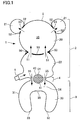
- FIG. 1 is a front view illustrating the balloon 1
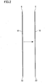
- FIG. 2 is a side view illustrating a process for producing the balloon 1.
- the balloon 1 includes two plastic films 10 and 12 (first film 10 and second film 12) (see FIG. 2 ) that are stacked and sealed at the peripheral edge 5.
- FIG. 1 is a front view illustrating the balloon 1 from the side of the first film 10 (i.e., plastic film), and the second film 12 is hidden behind the first film 10.
- the second film 12 that has the same shape as that of the first film 10 is provided opposite to the first film 10.
- the balloon 1 includes the first part 2, the second part 3, and the bending part 4 that is situated between the first part 2 and the second part 3.
- the balloon 1 according to the first embodiment is a clinging doll-type balloon toy that is designed so that the first part 2 forms a doll body part that imitates a bear, and the second part 3 forms a clinging part that can cling to a human arm or the like.
- the balloon 1 is not limited to a doll-type balloon toy, and the first part 2 need not necessarily imitate an animal (animal doll).
- the first part 2 may have a star-like shape, a heart-like shape, a circular shape, or the like, or may be designed to imitate a character (character doll) or the like.
- An advertisement or the like may be printed on the first part 2, for example.
- the first part 2 includes a large circular head 20, circular ears 21 that are respectively provided on the right side and the left side of the head 20, a body 22 that is provided under the head 20 and formed so that the limbs protrude therefrom, and an air supply valve 6 that is provided to the body 22 at a position corresponding to the right foot.
- the head 20 is connected to the ears 21 and the body 22 via a head sealed part 50 and an ear sealed part 52 (that are formed by welding part of the films situated opposite to each other), respectively.
- the head sealed part 50 and the ear sealed part 52 are formed along the circular contour of the head 20.
- a head gas passage 51 and an ear gas passage 53 are provided in an area in which the head 20 is connected to the ear 21 or the body 22. Therefore, the interior of the head 20 and the interior of the body 22 communicate with each other, and the interior of the head 20 and the interior of the ear 21 communicate with each other.
- the air supply valve 6 has a known film valve structure provided with a check valve.
- the air supply valve 6 is provided so that the front end of the air supply valve 6 is inserted into the first part 2, and the base end of the air supply valve 6 protrudes from the first part 2.
- the air supply valve 6 need not necessarily be provided to the first part 2.
- gas e.g., air
- the gas is supplied to the entire balloon 1.
- the air supply valve 6 may be removed so that only the part that functions as a check valve remains.
- the second part 3 is a clinging part that has an inverted U shape and opens downward in a front view.
- the second part 3 includes two arms 30 and 31 that are situated at such an interval that the arms 30 and 31 can hold a human arm or the like, end parts 32 and 33 that are respectively provided at the front end of the arms 30 and 31, and a connection part 34 that connects the base ends of the arms 30 and 31.
- the arms 30 and 31 slope inward from the connection part 34 to the end parts 32 and 33 so that the interval between the arms 30 and 31 slightly decreases.
- the end parts 32 and 33 are designed to be positioned at a predetermined interval.
- the interval between the end parts 32 and 33 decreases when the balloon 1 is filled with a gas to such an extent that the end parts 32 and 33 do not come in contact with each other.
- connection part 34 has an approximately arcuate shape.
- the connection part 34 is connected to the bending part 4 at the upper part of the peripheral edge 5, and includes a protrusion 35 that is situated at the lower part of the peripheral edge 5 (i.e., the inner edge of the clinging part) and slightly protrudes downward.
- the broken line drawn above the protrusion 35 indicates a known inner edge shape.
- the bending part 4 includes the gas passage 55 through which the interior of the first part 2 and the interior of the second part 3 communicate with each other, and the bending sealed part 54 that is formed by sealing the first film 10 and the second film 12 situated opposite to each other in an inward area relative to the peripheral edge 5.
- the bending part 4 bends when the balloon 1 is inflated so that the second part 3 is turned relative to the first part 2 to the first film 10 side or the second film 12 side.
- the outer edge 40 of the bending sealed part 54 extends beyond the bending part 4 so as to be situated within the first part 2 and the second part 3.
- first part 2 and the second part 3 are filled with a gas (i.e., inflated)
- the first part 2 and the second part 3 are deformed so that the first part 2 and the second part 3 have an approximately circular cross-sectional shape.
- tension is applied to the bending sealed part 54 within the first part 2 and the second part 3 in the direction in which the first part 2 and the second part 3 move away from each other.
- the tension applied to the bending sealed part 54 causes the bending part 4 to bend so that the second part 3 is turned relative to the first part 2.
- the outer edge 40 of the bending sealed part 54 is arched from the bending part 4 toward the first part 2 and the second part 3.
- the outer edge 40 is arched upward and downward to form an approximately elliptical shape.
- the outer edge 40 can be arched in at least one of the first part 2 and the second part 3.
- tension is applied to the bending sealed part 54 to only a small extent within the second part 3 when the bending sealed part 54 is formed to be equally situated within the first part 2 and the second part 3. Therefore, only part of the outer edge 40 of the bending sealed part 54 that extends within the second part 3 may be arched.
- the bending sealed part 54 may be formed so that the outer edge 40 is situated up to a greater depth within the second part 3 as compared with the first part 2.
- the bending sealed part 54 is preferably formed so that the bending sealed part 54 has the maximum depth within the first part 2 and the second part 3 in the vicinity of the center of the bending part 4 in the widthwise direction rather than in the vicinity of the peripheral edge 5. This is because tension is easily applied to the bending sealed part 54 in the vicinity of the center of the bending part 4 rather than in the vicinity of the peripheral edge 5.
- a plurality of bending sealed parts 54 may be provided along the widthwise direction of the bending part 4.
- a plurality of bending sealed parts 54 may be provided when producing a product in which the bending part 4 has a large width.
- At least one pair of gas passages 55 are provided on either side of the bending sealed part 54 in the widthwise direction of the bending part 4. Specifically, the gas passage 55 is formed in each unwelded area of the bending part 4 that is situated between the peripheral edge 5 and the bending sealed part 54.
- the number of gas passages 55 provided to the bending part 4 is not limited to 2, but may be 3 or more.
- a method for producing the balloon 1 is described below with reference to FIG. 2 .
- the first film 10 (plastic film) is stacked on the second film 12 (plastic film), and the first film 10 and the second film 12 are welded in a predetermined area (e.g., peripheral edge 5, head sealed part 50, ear sealed part 52, and bending sealed part 54 (see FIG. 1 )).
- a predetermined area e.g., peripheral edge 5, head sealed part 50, ear sealed part 52, and bending sealed part 54 (see FIG. 1 )
- a material used for producing a known synthetic resin balloon can be properly used as the material for forming the first film 10 and the second film 12.
- the first film 10 and the second film 12 may be a film on which a metal (e.g., aluminum) is deposited, or may be a film formed using a resin (e.g., ethylene-vinyl alcohol copolymer) that exhibits an excellent gas barrier capability, or may be a laminate in which a plurality of sheets are stacked.
- the first film 10 and the second film 12 can be welded using a known method (e.g., high-frequency welding, thermal welding, ultrasonic welding, or sealing and cutting).
- the first film 10 and the second film 12 are integrated by welding to provide seal-tightness.
- the balloon 1 illustrated in FIG. 1 can be produced by thus sealing the first film 10 and the second film 12 by welding.
- air supply valve 6 can be fitted to the first part 2 when sealing the first film 10 and the second film 12 at the peripheral edge 5.
- FIG. 3A is a front view illustrating the balloon 1 according to the first embodiment in an inflated state
- FIG. 3B is an enlarged view illustrating the bending part 4.
- FIG. 3A the balloon 1 is inflated when a gas is injected into the balloon 1 through the air supply valve 6.
- the bending part 4 bends so that the second part 3 is turned backward or forward. Note that FIG. 3A illustrates a state in which the bending part 4 does not bend for convenience of explanation of a change in entire shape and the like.
- the second part 3 is deformed when inflated so that the end part 32 of the arm 30 and the end part 33 of the arm 31 approach each other to form an approximately ring-like shape.
- the end parts 32 and 33 are opened, and the arms 30 and 31 are caused to cling to (hold) the arm of the user, for example.
- connection part 34 includes the protrusion 35 that protrudes into the inner space defined by the approximately ring-like shape at a position opposite to the bending part 4, it is possible to prevent a situation in which wrinkles are formed in the vicinity of the center of the connection part 34 when the balloon 1 is inflated. Since the bending sealed part 54 is situated in the vicinity of the center of the connection part 34, the radius of a circle formed by the cross section decreases as compared with each side in the widthwise direction when the protrusion 35 is not provided, and wrinkles are formed in the connection part 34.
- the protrusion 35 can prevent a situation in which the radius of a circle formed by the cross section in the vicinity of the center of the connection part 34 decreases as compared with each side of the connection part 34 (i.e., wrinkles are rarely formed in the connection part 34), it is possible to provide a product that exhibits an excellent external appearance.
- the bending sealed part 54 includes the outer edge 40, and a flat part 41 that is surrounded by the outer edge 40, the flat part 41 is formed by welding the first film 10 and the second film 12.
- the flat part 41 may be formed by welding the first film 10 and the second film 12 over the entire bending sealed part 54, or may be formed by welding the first film 10 and the second film 12 only in the vicinity of the outer edge 40. It is preferable to form the flat part 41 by welding the first film 10 and the second film 12 over the entire bending sealed part 54 so that the flat part 41 can withstand tension that is applied to the bending sealed part 54.
- the body 22 and the connection part 34 that are contiguous to the bending part 4 are deformed when the balloon 1 is inflated, and the outer edge 40 of the bending sealed part 54 is to be deformed as indicated by the broken line.
- tension that moves the first part 2 and the second part 3 away from each other
- tension increases in a center flat part 41a that is situated away from the peripheral edge 5 as compared with an edge flat part 41b that is situated close to the peripheral edge 5. It is considered that the second part 3 is turned relative to the first part 2 due to the difference in tension between the center and each side of the bending sealed part 54.
- the gas passage 55 is expanded on each side of the bending sealed part 54 in the widthwise direction to form a pillar 42.
- the pillar 42 bends together with the bending part 4 while allowing gas to pass through.
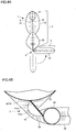
- FIG. 4A is a side view illustrating the balloon 1 in an inflated state
- FIG. 4B is an enlarged cross-sectional view illustrating the bending part 4 taken along the line IV-IV illustrated in FIG. 5.
- FIG. 5 is a front view illustrating the balloon 1 in an inflated state in which the second part 3 is turned backward.
- FIG. 6 is a photograph of the balloon 1 captured from an oblique lower-right front side.
- the second part 3 is turned to the right (i.e., the side where the second film 12 is situated) around the bending part 4, and forms approximately a right angle with the first part 2.
- the bending sealed part 54 provided to the bending part 4 is pulled between the body 22 and the connection part 34, and deformed (i.e., the pillar 42 is bent) so that the body 22 and the connection part 34 approach each other on the right side in FIG. 4B .
- Tension is always applied to the bending sealed part 54 in the direction in which the second part 3 approaches the first part 2, and causes the second part 3 to be turned at approximately a right angle when the second part 3 has moved away from the first part 2. Therefore, it is unnecessary to provide a bent state-holding member (double-sided pressure-sensitive adhesive tape) such as that disclosed in Patent Literature 1 that maintains the balloon in a bent state.
- a bent state-holding member such as that disclosed in Patent Literature 1 may be used as an auxiliary member when it is desired to necessarily maintain the balloon in a bent state.
- the balloon 1 was produced, and inflated (see FIG. 6 ).
- the bending part 4 bent spontaneously, and the bent state was maintained as long as an external force was not applied.
- an external force was applied to the balloon 1 so as to move the second part 3 away from the first part 2 (i.e., unbend the balloon 1 as illustrated in FIG. 3A ), and then removed, the bending part 4 bent spontaneously, and the bent state was recovered.
- the balloon 1 that is produced by sealing two plastic films (plastic films 10 and 12) can maintain a bent state in a state in which the balloon is filled with a gas.
- the expression "maintain a bent state” used herein means that the balloon 1 maintains a bent state as long as an external force is not applied to the balloon 1 (i.e., maintains a bent state independently of the weight of the balloon 1).
- FIG. 7 is a front view illustrating the balloon 71 of Comparative Example 1
- FIG. 8 is a photograph of the balloon 71 of Comparative Example 1 captured from the front side. Said Comparative Example 1 is particularly useful for understanding the present invention.
- the balloon 71 is produced by sealing two plastic films at a peripheral edge 75.
- the balloon 71 includes a first part 72, a second part 73, and a bending part 74, the first part 72 and the second part 73 being situated on either side of the bending part 74.
- the balloon 71 of Comparative Example 1 has an approximately rectangular (quadrangular) external shape when viewed from the front side, and the bending part 74 is formed to extend in the vicinity of the center of the balloon 71.
- the bending part 74 includes a sealed part 77 that is linearly and narrowly formed by welding so as to have a small width.
- the sealed part 77 is disconnected in two areas, in which a gas passage 78 is formed.
- FIG. 8 that illustrates the balloon 71 of Comparative Example 1 in an inflated state
- the bending part 74 did not bend spontaneously.
- the state illustrated in FIG. 8 was recovered (i.e., the balloon 71 could not maintain the bent state).
- the resulting balloon could not maintain the bent state.
- FIG. 9 is a front view illustrating the balloon 91
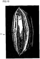
- FIG. 10 is a photograph of the balloon 91 captured from the front side.
- the balloon 91 is basically the same as the balloon 71 of Comparative Example 1, except for the configuration of a bending part 94. Note that description of the same features as those described above in connection with Comparative Example 1 is omitted.
- the bending part 94 includes a bending sealed part 97 that has an outer edge 99 that has a large depth within a first part 92 and a second part 93 in the vicinity of the center thereof, and decreases in width toward a peripheral edge 95.
- the bending sealed part 97 is formed by welding two plastic films.
- a gas passage 98 is formed between the bending sealed part 97 and the peripheral edge 95.
- FIG. 10 that illustrates the balloon 91 in an inflated state
- the balloon 91 bent spontaneously, and could maintain the bent state.
- the bending part 94 of the balloon 91 in an inflated state was unbent, and released, the state illustrated in FIG. 10 was immediately recovered.
- the bending sealed part 97 is tense in the vicinity of the center of the bending part 94 (i.e., high tension is applied), and wrinkles are formed as the distance from the peripheral edge 95 decreases (i.e., low tension is applied).
- FIG. 11 is a photograph of the balloon 91a of Comparative Example 2 captured from the front side. Said Comparative Example 2 is also particularly useful for understanding the present invention.
- the balloon 91a Since a through-hole is formed in the area surrounded by the outer edge 99, the balloon 91a does not include the bending sealed part 97.
- the bending part of the balloon 91a bent due to the weight of the balloon 91a.
- the bending part bent in the opposite direction due to the weight of the balloon 91a (i.e., the balloon 91a could not maintain the bent state).
- a balloon was produced in the same manner as the balloon 91, except that a plurality of (nine) circular sealed parts (having an identical size) were provided through (eight) gas passages instead of the bending sealed part 97.
- the resulting balloon could maintain a bent state in the same manner as the balloon 91 (see FIG. 10 ).
- FIG. 12 is a front view illustrating the balloon 61
- FIG. 13 is a photograph of the balloon 61 according to the third embodiment captured from an oblique upper rear side
- FIG. 14 is a photograph of the balloon 61 according to the third embodiment captured from an oblique upper-left rear side.
- the balloon 61 includes a plurality of (four) first parts 62 and one second part 63.
- the second part 63 is a clinging part having an inverted U shape.
- a bending part 64 is provided between each of the four first parts 62 and the second part 63, and a bending sealed part 67 is formed in each bending part 4.
- the bending sealed part 67 is formed by welding two plastic films at a peripheral edge 65 (see the first embodiment).
- the bending part 64 includes gas passages 68 that are provided on either side of the bending sealed part 67.
- an air supply valve 66 When air is injected into the balloon 61 through an air supply valve 66, the air flows into the first parts 62 and the second part 63 through the gas passages 68 (i.e., the balloon 61 is inflated).
- the structure of the bending sealed part 67 is the same as that described above in connection with the first embodiment.
- the outer edge of the bending sealed part 67 extends beyond the bending part 64 so as to be situated within the first part 62 and the second part 63.
- each bending part 64 bends spontaneously, and the four (circular) first parts 62 are turned relative to the second part 63 (see FIG. 13 ).
- the direction in which each first part 62 is turned can be set independently. For example, only one first part 62 can be turned in a different direction (see FIG. 14 ).
- the second part 63 may be a clinging part that includes end parts 69 and has an approximately ring-like shape.
- the second part 63 can be fitted to a human arm or the like.
- the balloon 61 could maintain the state in which the first parts 62 were turned relative to the second part 63.
- the invention is not limited to the above embodiments.
- the invention includes various modifications and design variations that can be implemented without departing from the scope of the invention.
Landscapes
- Toys (AREA)
Description
- The present invention relates to a balloon that can maintain a bent state even when the balloon is filled with a gas.
- A clinging (embraceable) doll-type balloon toy that is fitted to a human arm or the like is known. For example, when such a balloon is designed to imitate an animal (animal doll) or a character (character doll), the face of the animal or the character faces forward when the balloon is fitted to a human arm or the like. A film material that forms a front member (front part), a film material that forms a rear member (rear part), and a film material that forms a bottom member (bottom part) are required so that the body of the balloon forms a right angle with a clinging member that is fitted to a human arm or the like.
- In recent years, a film balloon that is formed by sealing two plastic films has been developed, and a clinging doll-type balloon toy that is formed by sealing two plastic films has been proposed (see
Patent Literature 1, for example). Since such a clinging doll-type balloon toy can be easily produced as compared with a clinging doll-type balloon toy that is produced by combining three films in a complex manner, such a clinging doll-type balloon toy can be mass-produced. However, since such a clinging doll-type balloon toy is produced using two plastic films, it is necessary to bend the clinging doll-type balloon toy so that the body of the balloon forms a right angle with the clinging member, and provide a special bent state-holding member (double-sided pressure-sensitive adhesive tape) that maintains the bent state. - Patent document
JP1690041 U - Patent document
6575805B1 - Patent document
US5023118 A discloses an artificial inflated flower composed of individual inflated petals and/or petal assemblies. Selected portions of the petals and petal assemblies are sealed together along heat-fused seams to impart a generally flattened shape to each petal and assembly. - Patent document
WO01/70593 A1 - Patent document
US 5480029 A discloses a packaging component which is made of a first generally rectangular plastic element and a second generally oval plastic element, each of such elements being inflatable and deflatable. A plastic coupling element couples the first and second elements and a valve is used to permit air under pressure to be supplied to, or to be released from, the first and second elements so that they can be inflated and deflated. - PTL 1: Japanese Utility Model Registration No.
3169041 - An object of the invention is to provide a balloon that can maintain a bent state even if a bent state-holding member (double-sided pressure-sensitive adhesive tape) is not used.
- The present invention provides a toy balloon according to
claim 1. - The invention was conceived in order to solve at least some of the above problems, and may be implemented as described below (see the following aspects and application examples).
- According to one aspect of the invention, a balloon (1) includes two plastic films (10, 12) that are stacked and sealed at a peripheral edge (5),
the balloon (1) including a first part (2), a second part (3), and a bending part (4) that is situated between the first part (2) and the second part (3),
the bending part (4) including a gas passage (55) through which the interior of the first part (2) and the interior of the second part (3) communicate with each other, and a bending sealed part (54) that is formed by sealing the two plastic films (10, 12) situated opposite to each other in an inward area relative to the peripheral edge (5), and
an outer edge (40) of the bending sealed part (54) extending beyond the bending part (4) so as to be situated within the first part (2) and the second part (3). - In the balloon (1), the outer edge (40) of the bending sealed part (54) may be arched from the bending part (4) toward at least one of the first part (2) and the second part (3).
- In the balloon (1), at least one pair of the gas passages (55) may be provided on either side of the bending sealed part (54) in the widthwise direction of the bending part (4).
- In the balloon (1), a plurality of the bending sealed parts (54) may be formed along the widthwise direction of the bending part (4).
- In the balloon (1), the bending part (4) may bend due to tension applied to the bending sealed part (54) by filling the balloon with a gas and inflating the balloon so that the second part (3) may be turned relative to the first part (2).
- In the balloon (1), the first part (2) may be a body of a doll, and the second part (3) may be a clinging part by which the balloon is fitted to a human arm or the like.
- In the balloon (1), the clinging part may include two arms (30, 31), end parts (32, 33) of the two arms, and a connection part (34) that connects base ends of the two arms (30, 31), and form an approximately ring-like shape when the balloon (1) is filled with a gas and inflated, and the connection part (34) may include a protrusion (35) that protrudes into the inner space defined by the approximately ring-like shape at a position opposite to the bending part (4).
- The balloon according to the invention that is produced by sealing two plastic films can thus maintain a bent state in a state in which the balloon is filled with a gas.
-
-
FIG. 1 is a front view illustrating a balloon according to the first embodiment. -
FIG. 2 is a side view illustrating a process for producing a balloon according to the first embodiment. -
FIG. 3A is a front view illustrating a balloon in an inflated state according to the first embodiment. -
FIG. 3B is an enlarged view illustrating a bending part. -
FIG. 4A is a side view illustrating a balloon in an inflated state according to the first embodiment. -
FIG. 4B is an enlarged vertical cross-sectional view illustrating a bending part, taken along the line IV-IV inFIG. 5 . -
FIG. 5 is a front view illustrating a balloon in an inflated state in which a second part is turned according to the first embodiment. -
FIG. 6 is a photograph of a balloon captured from an oblique lower-right front side (first embodiment). -
FIG. 7 is a front view illustrating a balloon in Comparative Example 1, which is useful for understanding the present invention. -
FIG. 8 is a photograph of a balloon in Comparative Example 1, which is useful for understanding the present invention, captured from the front side. -
FIG. 9 is a front view illustrating a balloon according to the second embodiment. -
FIG. 10 is a photograph of a balloon according to the second embodiment captured from the front side. -
FIG. 11 is a photograph of a balloon in Comparative Example 2, which is also useful for understanding the present invention, captured from the front side. -
FIG. 12 is a front view illustrating a balloon according to the third embodiment. -
FIG. 13 is a photograph of a balloon according to the third embodiment captured from an oblique upper rear side. -
FIG. 14 is a photograph of a balloon according to the third embodiment captured from an oblique upper-left rear side. - Exemplary embodiments of the invention are described in detail below with reference to the drawings.
- A
balloon 1 according to one embodiment of the invention includes twoplastic films peripheral edge 5, theballoon 1 including afirst part 2, asecond part 3, and abending part 4 that is situated between thefirst part 2 and thesecond part 3, thebending part 4 including agas passage 55 through which the interior of thefirst part 2 and the interior of thesecond part 3 communicate with each other, and a bending sealedpart 54 that is formed by sealing the twoplastic films peripheral edge 5, and anouter edge 40 of the bending sealedpart 54 extending beyond thebending part 4 so as to be situated within thefirst part 2 and thesecond part 3. - The configuration of a
balloon 1 according to the first embodiment of the invention is described below with reference toFIGS. 1 and2 .FIG. 1 is a front view illustrating theballoon 1, andFIG. 2 is a side view illustrating a process for producing theballoon 1. - As illustrated in
FIG. 1 , theballoon 1 includes twoplastic films 10 and 12 (first film 10 and second film 12) (seeFIG. 2 ) that are stacked and sealed at theperipheral edge 5. Note thatFIG. 1 is a front view illustrating theballoon 1 from the side of the first film 10 (i.e., plastic film), and thesecond film 12 is hidden behind thefirst film 10. Thesecond film 12 that has the same shape as that of thefirst film 10 is provided opposite to thefirst film 10. - The
balloon 1 includes thefirst part 2, thesecond part 3, and the bendingpart 4 that is situated between thefirst part 2 and thesecond part 3. Theballoon 1 according to the first embodiment is a clinging doll-type balloon toy that is designed so that thefirst part 2 forms a doll body part that imitates a bear, and thesecond part 3 forms a clinging part that can cling to a human arm or the like. Note that theballoon 1 is not limited to a doll-type balloon toy, and thefirst part 2 need not necessarily imitate an animal (animal doll). Thefirst part 2 may have a star-like shape, a heart-like shape, a circular shape, or the like, or may be designed to imitate a character (character doll) or the like. An advertisement or the like may be printed on thefirst part 2, for example. - The
first part 2 includes a largecircular head 20,circular ears 21 that are respectively provided on the right side and the left side of thehead 20, abody 22 that is provided under thehead 20 and formed so that the limbs protrude therefrom, and anair supply valve 6 that is provided to thebody 22 at a position corresponding to the right foot. - The
head 20 is connected to theears 21 and thebody 22 via a head sealedpart 50 and an ear sealed part 52 (that are formed by welding part of the films situated opposite to each other), respectively. The head sealedpart 50 and the ear sealedpart 52 are formed along the circular contour of thehead 20. Ahead gas passage 51 and an ear gas passage 53 (that are formed by not welding the films situated opposite to each other) are provided in an area in which thehead 20 is connected to theear 21 or thebody 22. Therefore, the interior of thehead 20 and the interior of thebody 22 communicate with each other, and the interior of thehead 20 and the interior of theear 21 communicate with each other. - A detailed description of the structure of the
air supply valve 6 is omitted. Theair supply valve 6 has a known film valve structure provided with a check valve. Theair supply valve 6 is provided so that the front end of theair supply valve 6 is inserted into thefirst part 2, and the base end of theair supply valve 6 protrudes from thefirst part 2. Theair supply valve 6 need not necessarily be provided to thefirst part 2. When gas (e.g., air) is supplied to the interior of thefirst part 2, the gas is supplied to theentire balloon 1. After inflating theballoon 1, theair supply valve 6 may be removed so that only the part that functions as a check valve remains. - The
second part 3 is a clinging part that has an inverted U shape and opens downward in a front view. Thesecond part 3 includes twoarms arms parts arms connection part 34 that connects the base ends of thearms - The
arms connection part 34 to theend parts arms - The
end parts end parts balloon 1 is filled with a gas to such an extent that theend parts - The
connection part 34 has an approximately arcuate shape. Theconnection part 34 is connected to the bendingpart 4 at the upper part of theperipheral edge 5, and includes aprotrusion 35 that is situated at the lower part of the peripheral edge 5 (i.e., the inner edge of the clinging part) and slightly protrudes downward. InFIG. 1 , the broken line drawn above theprotrusion 35 indicates a known inner edge shape. - The bending
part 4 includes thegas passage 55 through which the interior of thefirst part 2 and the interior of thesecond part 3 communicate with each other, and the bending sealedpart 54 that is formed by sealing thefirst film 10 and thesecond film 12 situated opposite to each other in an inward area relative to theperipheral edge 5. The bendingpart 4 bends when theballoon 1 is inflated so that thesecond part 3 is turned relative to thefirst part 2 to thefirst film 10 side or thesecond film 12 side. - The
outer edge 40 of the bending sealedpart 54 extends beyond the bendingpart 4 so as to be situated within thefirst part 2 and thesecond part 3. When thefirst part 2 and thesecond part 3 are filled with a gas (i.e., inflated), thefirst part 2 and thesecond part 3 are deformed so that thefirst part 2 and thesecond part 3 have an approximately circular cross-sectional shape. In this case, tension is applied to the bending sealedpart 54 within thefirst part 2 and thesecond part 3 in the direction in which thefirst part 2 and thesecond part 3 move away from each other. The tension applied to the bending sealedpart 54 causes the bendingpart 4 to bend so that thesecond part 3 is turned relative to thefirst part 2. - The
outer edge 40 of the bending sealedpart 54 is arched from the bendingpart 4 toward thefirst part 2 and thesecond part 3. InFIG. 1 , theouter edge 40 is arched upward and downward to form an approximately elliptical shape. Note that theouter edge 40 can be arched in at least one of thefirst part 2 and thesecond part 3. For example, when the vertical dimension of thesecond part 3 is shorter than that of the first part 2 (seeFIG. 1 ), tension is applied to the bending sealedpart 54 to only a small extent within thesecond part 3 when the bending sealedpart 54 is formed to be equally situated within thefirst part 2 and thesecond part 3. Therefore, only part of theouter edge 40 of the bending sealedpart 54 that extends within thesecond part 3 may be arched. The bending sealedpart 54 may be formed so that theouter edge 40 is situated up to a greater depth within thesecond part 3 as compared with thefirst part 2. - The bending sealed
part 54 is preferably formed so that the bending sealedpart 54 has the maximum depth within thefirst part 2 and thesecond part 3 in the vicinity of the center of the bendingpart 4 in the widthwise direction rather than in the vicinity of theperipheral edge 5. This is because tension is easily applied to the bending sealedpart 54 in the vicinity of the center of the bendingpart 4 rather than in the vicinity of theperipheral edge 5. - Although an example in which one bending sealed
part 54 is provided at the center of the bendingpart 4 in the widthwise direction has been described above, the configuration is not limited thereto. For example, a plurality of bending sealedparts 54 may be provided along the widthwise direction of the bendingpart 4. For example, a plurality of bending sealedparts 54 may be provided when producing a product in which thebending part 4 has a large width. - At least one pair of
gas passages 55 are provided on either side of the bending sealedpart 54 in the widthwise direction of the bendingpart 4. Specifically, thegas passage 55 is formed in each unwelded area of the bendingpart 4 that is situated between theperipheral edge 5 and the bending sealedpart 54. The number ofgas passages 55 provided to the bendingpart 4 is not limited to 2, but may be 3 or more. - A method for producing the
balloon 1 is described below with reference toFIG. 2 . - As illustrated in
FIG. 2 , the first film 10 (plastic film) is stacked on the second film 12 (plastic film), and thefirst film 10 and thesecond film 12 are welded in a predetermined area (e.g.,peripheral edge 5, head sealedpart 50, ear sealedpart 52, and bending sealed part 54 (seeFIG. 1 )). - A material used for producing a known synthetic resin balloon (e.g., polyethylene, polypropylene, polyester, polyamide, or vinyl chloride) can be properly used as the material for forming the
first film 10 and thesecond film 12. Thefirst film 10 and thesecond film 12 may be a film on which a metal (e.g., aluminum) is deposited, or may be a film formed using a resin (e.g., ethylene-vinyl alcohol copolymer) that exhibits an excellent gas barrier capability, or may be a laminate in which a plurality of sheets are stacked. - The
first film 10 and thesecond film 12 can be welded using a known method (e.g., high-frequency welding, thermal welding, ultrasonic welding, or sealing and cutting). Thefirst film 10 and thesecond film 12 are integrated by welding to provide seal-tightness. - The
balloon 1 illustrated inFIG. 1 can be produced by thus sealing thefirst film 10 and thesecond film 12 by welding. - Note that the
air supply valve 6 can be fitted to thefirst part 2 when sealing thefirst film 10 and thesecond film 12 at theperipheral edge 5. - The
balloon 1 in an inflated state is described below with reference toFIGS. 3A to 6 .FIG. 3A is a front view illustrating theballoon 1 according to the first embodiment in an inflated state, andFIG. 3B is an enlarged view illustrating the bendingpart 4. - As illustrated in
FIG. 3A , theballoon 1 is inflated when a gas is injected into theballoon 1 through theair supply valve 6. As illustrated inFIGS. 4A and5 , the bendingpart 4 bends so that thesecond part 3 is turned backward or forward. Note thatFIG. 3A illustrates a state in which thebending part 4 does not bend for convenience of explanation of a change in entire shape and the like. - The
second part 3 is deformed when inflated so that theend part 32 of thearm 30 and theend part 33 of thearm 31 approach each other to form an approximately ring-like shape. When using theballoon 1, theend parts arms - Since the
connection part 34 includes theprotrusion 35 that protrudes into the inner space defined by the approximately ring-like shape at a position opposite to the bendingpart 4, it is possible to prevent a situation in which wrinkles are formed in the vicinity of the center of theconnection part 34 when theballoon 1 is inflated. Since the bending sealedpart 54 is situated in the vicinity of the center of theconnection part 34, the radius of a circle formed by the cross section decreases as compared with each side in the widthwise direction when theprotrusion 35 is not provided, and wrinkles are formed in theconnection part 34. Since theprotrusion 35 can prevent a situation in which the radius of a circle formed by the cross section in the vicinity of the center of theconnection part 34 decreases as compared with each side of the connection part 34 (i.e., wrinkles are rarely formed in the connection part 34), it is possible to provide a product that exhibits an excellent external appearance. - The bending sealed
part 54 includes theouter edge 40, and aflat part 41 that is surrounded by theouter edge 40, theflat part 41 is formed by welding thefirst film 10 and thesecond film 12. Theflat part 41 may be formed by welding thefirst film 10 and thesecond film 12 over the entire bending sealedpart 54, or may be formed by welding thefirst film 10 and thesecond film 12 only in the vicinity of theouter edge 40. It is preferable to form theflat part 41 by welding thefirst film 10 and thesecond film 12 over the entire bending sealedpart 54 so that theflat part 41 can withstand tension that is applied to the bending sealedpart 54. - As illustrated in
FIG. 3B , thebody 22 and theconnection part 34 that are contiguous to the bendingpart 4 are deformed when theballoon 1 is inflated, and theouter edge 40 of the bending sealedpart 54 is to be deformed as indicated by the broken line. - Therefore, tension (that moves the
first part 2 and thesecond part 3 away from each other) applied to the bending sealedpart 54 increases in a centerflat part 41a that is situated away from theperipheral edge 5 as compared with an edgeflat part 41b that is situated close to theperipheral edge 5. It is considered that thesecond part 3 is turned relative to thefirst part 2 due to the difference in tension between the center and each side of the bending sealedpart 54. - The
gas passage 55 is expanded on each side of the bending sealedpart 54 in the widthwise direction to form a pillar 42. The pillar 42 bends together with the bendingpart 4 while allowing gas to pass through. - The
balloon 1 in a bent state is described below with reference toFIGS. 4A to 6 .FIG. 4A is a side view illustrating theballoon 1 in an inflated state, andFIG. 4B is an enlarged cross-sectional view illustrating the bendingpart 4 taken along the line IV-IV illustrated inFIG. 5. FIG. 5 is a front view illustrating theballoon 1 in an inflated state in which thesecond part 3 is turned backward.FIG. 6 is a photograph of theballoon 1 captured from an oblique lower-right front side. - As illustrated in
FIG. 4A , thesecond part 3 is turned to the right (i.e., the side where thesecond film 12 is situated) around the bendingpart 4, and forms approximately a right angle with thefirst part 2. - As illustrated in
FIG. 4B , the bending sealedpart 54 provided to the bendingpart 4 is pulled between thebody 22 and theconnection part 34, and deformed (i.e., the pillar 42 is bent) so that thebody 22 and theconnection part 34 approach each other on the right side inFIG. 4B . - Tension is always applied to the bending sealed
part 54 in the direction in which thesecond part 3 approaches thefirst part 2, and causes thesecond part 3 to be turned at approximately a right angle when thesecond part 3 has moved away from thefirst part 2. Therefore, it is unnecessary to provide a bent state-holding member (double-sided pressure-sensitive adhesive tape) such as that disclosed inPatent Literature 1 that maintains the balloon in a bent state. Note that a bent state-holding member such as that disclosed inPatent Literature 1 may be used as an auxiliary member when it is desired to necessarily maintain the balloon in a bent state. - As illustrated in
FIG. 5 , small wrinkles are formed in the vicinity of the center of theconnection part 34 in the widthwise direction. However, the size of the wrinkles is reduced due to the effect of theprotrusion 35 described above with reference toFIG. 3A and Fig. 3B , and the external appearance of theballoon 1 is affected to only a small extent. - The
balloon 1 was produced, and inflated (seeFIG. 6 ). When theballoon 1 was filled with air, the bendingpart 4 bent spontaneously, and the bent state was maintained as long as an external force was not applied. When an external force was applied to theballoon 1 so as to move thesecond part 3 away from the first part 2 (i.e., unbend theballoon 1 as illustrated inFIG. 3A ), and then removed, the bendingpart 4 bent spontaneously, and the bent state was recovered. - As described above, the
balloon 1 that is produced by sealing two plastic films (plastic films 10 and 12) can maintain a bent state in a state in which the balloon is filled with a gas. Note that the expression "maintain a bent state" used herein means that theballoon 1 maintains a bent state as long as an external force is not applied to the balloon 1 (i.e., maintains a bent state independently of the weight of the balloon 1). - A
balloon 71 of Comparative Example 1 that differs from theballoon 1 as to the configuration of the bending part is described below with reference toFIGS. 7 and8 .FIG. 7 is a front view illustrating theballoon 71 of Comparative Example 1, andFIG. 8 is a photograph of theballoon 71 of Comparative Example 1 captured from the front side. Said Comparative Example 1 is particularly useful for understanding the present invention. - As illustrated in
FIG. 7 , theballoon 71 is produced by sealing two plastic films at aperipheral edge 75. Theballoon 71 includes afirst part 72, asecond part 73, and a bendingpart 74, thefirst part 72 and thesecond part 73 being situated on either side of the bendingpart 74. Theballoon 71 of Comparative Example 1 has an approximately rectangular (quadrangular) external shape when viewed from the front side, and the bendingpart 74 is formed to extend in the vicinity of the center of theballoon 71. - The bending
part 74 includes a sealedpart 77 that is linearly and narrowly formed by welding so as to have a small width. The sealedpart 77 is disconnected in two areas, in which agas passage 78 is formed. - When air is injected into the
balloon 71 through anair supply valve 76 that is provided to protrude from the vicinity of the center of one side of theballoon 71, the air flows into thesecond part 73 from thefirst part 72 through the gas passages 78 (i.e., theentire balloon 71 is inflated). - As illustrated in
FIG. 8 (that illustrates theballoon 71 of Comparative Example 1 in an inflated state), the bendingpart 74 did not bend spontaneously. When the bendingpart 74 of theballoon 71 in an inflated state was bent, the state illustrated inFIG. 8 was recovered (i.e., theballoon 71 could not maintain the bent state). - A balloon in which the width (i.e., the dimension in the rightward-leftward direction in
FIG. 7 ) of the sealedpart 77 was increased to have a rectangular shape, and thegas passage 78 was provided on each end of the sealedpart 77 was also produced. However, the resulting balloon could not maintain the bent state. - A
balloon 91 according to the second embodiment of the invention that differs from theballoon 71 as to the configuration of the bending part is described below with reference toFIGS. 9 and10 .FIG. 9 is a front view illustrating theballoon 91, andFIG. 10 is a photograph of theballoon 91 captured from the front side. - As illustrated in
FIG. 9 , theballoon 91 is basically the same as theballoon 71 of Comparative Example 1, except for the configuration of a bendingpart 94. Note that description of the same features as those described above in connection with Comparative Example 1 is omitted. - The bending
part 94 includes a bending sealedpart 97 that has anouter edge 99 that has a large depth within afirst part 92 and asecond part 93 in the vicinity of the center thereof, and decreases in width toward aperipheral edge 95. The bending sealedpart 97 is formed by welding two plastic films. - A
gas passage 98 is formed between the bending sealedpart 97 and theperipheral edge 95. - When air is injected into the
balloon 91 through anair supply valve 96 that is provided to theballoon 91, theentire balloon 91 is inflated. - As illustrated in
FIG. 10 (that illustrates theballoon 91 in an inflated state), the balloon 91 (bending part 94) bent spontaneously, and could maintain the bent state. When the bendingpart 94 of theballoon 91 in an inflated state was unbent, and released, the state illustrated inFIG. 10 was immediately recovered. - As illustrated in
FIG. 10 , the bending sealedpart 97 is tense in the vicinity of the center of the bending part 94 (i.e., high tension is applied), and wrinkles are formed as the distance from theperipheral edge 95 decreases (i.e., low tension is applied). - A
balloon 91a of Comparative Example 2 that differs from theballoon 91 according to the second embodiment in that the area of the bending sealedpart 97 surrounded by theouter edge 99 was removed is described below.FIG. 11 is a photograph of theballoon 91a of Comparative Example 2 captured from the front side. Said Comparative Example 2 is also particularly useful for understanding the present invention. - Since a through-hole is formed in the area surrounded by the
outer edge 99, theballoon 91a does not include the bending sealedpart 97. - As illustrated in
FIG. 11 , the bending part of theballoon 91a bent due to the weight of theballoon 91a. However, when theballoon 91a was raised and turned over, the bending part bent in the opposite direction due to the weight of theballoon 91a (i.e., theballoon 91a could not maintain the bent state). - A balloon was produced in the same manner as the
balloon 91, except that a plurality of (nine) circular sealed parts (having an identical size) were provided through (eight) gas passages instead of the bending sealedpart 97. The resulting balloon could maintain a bent state in the same manner as the balloon 91 (seeFIG. 10 ). - A
balloon 61 according to the third embodiment of the invention that includes a plurality offirst parts 62 is described below with reference toFIGS. 12 to 14 .FIG. 12 is a front view illustrating theballoon 61,FIG. 13 is a photograph of theballoon 61 according to the third embodiment captured from an oblique upper rear side, andFIG. 14 is a photograph of theballoon 61 according to the third embodiment captured from an oblique upper-left rear side. - As illustrated in
FIG. 12 , theballoon 61 includes a plurality of (four)first parts 62 and onesecond part 63. Thesecond part 63 is a clinging part having an inverted U shape. - A bending
part 64 is provided between each of the fourfirst parts 62 and thesecond part 63, and a bending sealedpart 67 is formed in each bendingpart 4. The bending sealedpart 67 is formed by welding two plastic films at a peripheral edge 65 (see the first embodiment). - The bending
part 64 includesgas passages 68 that are provided on either side of the bending sealedpart 67. When air is injected into theballoon 61 through anair supply valve 66, the air flows into thefirst parts 62 and thesecond part 63 through the gas passages 68 (i.e., theballoon 61 is inflated). - The structure of the bending sealed
part 67 is the same as that described above in connection with the first embodiment. The outer edge of the bending sealedpart 67 extends beyond the bendingpart 64 so as to be situated within thefirst part 62 and thesecond part 63. - Therefore, when the
balloon 61 is inflated, each bendingpart 64 bends spontaneously, and the four (circular)first parts 62 are turned relative to the second part 63 (seeFIG. 13 ). The direction in which eachfirst part 62 is turned can be set independently. For example, only onefirst part 62 can be turned in a different direction (seeFIG. 14 ). - The
second part 63 may be a clinging part that includesend parts 69 and has an approximately ring-like shape. Thesecond part 63 can be fitted to a human arm or the like. - The
balloon 61 could maintain the state in which thefirst parts 62 were turned relative to thesecond part 63. - The invention is not limited to the above embodiments. The invention includes various modifications and design variations that can be implemented without departing from the scope of the invention.
- 1: balloon, 2: first part, 3: second part, 4: bending part, 5: peripheral edge, 6: air supply valve, 10: first film, 12: second film, 20: head, 21: ear, 22: body, 30: arm, 31: arm, 32: end part, 33: end part, 34: connection part, 35: protrusion, 40: outer edge, 41: flat part, 41a: center flat part, 41b: edge flat part, 42: pillar, 50: head sealed part, 51: gas passage, 52: ear sealed part, 53: gas passage, 54: bending sealed part, 55: gas passage, 61: balloon, 62: first part, 63: second part, 64: bending part, 65: peripheral edge, 66: air supply valve, 67: bending sealed part, 68: gas passage, 69: end part, 71: balloon, 72: first part, 73: second part, 74: bending part, 75: peripheral edge, 76: air supply valve, 77: sealed part, 78: gas passage, 91: balloon, 91a: balloon, 92: first part, 93: second part, 94: bending part, 95: peripheral edge, 96: air supply valve, 97: bending sealed part, 98: gas passage, 99: outer edge
Claims (6)
- A toy balloon (1, 61, 71, 91, 91a) comprising two plastic films that are stacked and sealed at a peripheral edge (5, 65, 75, 95),
the toy balloon (1, 61, 71, 91, 91a) including a first part (2, 62, 72, 92), a second part (3, 63, 73, 93), and a bending part (4, 64, 74, 94) that is situated between the first part (2, 62, 72, 92) and the second part (3, 63, 73, 93),
the bending part (4, 64, 74, 94) including a gas passage (51, 53, 55, 68, 78, 98) through which an interior of the first part (2, 62, 72, 92) and an interior of the second part (3, 63, 73, 93) communicate with each other, and a bending sealed part (54, 67, 97) that is formed by sealing the two plastic films situated opposite to each other in an inward area relative to the peripheral edge (5, 65, 75, 95), characterized in that
an outer edge (40) of the bending sealed part (54, 67, 97) extending beyond the bending part (4, 64, 74, 94) so as to be situated within the first part (2, 62, 72, 92) and the second part (3, 63, 73, 93), and no through-hole being formed inside the outer edge; wherein, the bending part (4, 64, 74, 94) bends due to tension applied to the bending sealed part (54, 67, 97) by filling the toy balloon (1, 61, 71, 91, 91a) with a gas and inflating the toy balloon (1) so that the second part (3, 63, 73, 93) is spontaneously turned relative to the first part (2, 62, 72, 92) and a bent state of the toy balloon is maintained. - The toy balloon (1, 61, 71, 91, 91a) as defined in claim 1,
wherein the outer edge (40) of the bending sealed part (54, 67, 97) is arched from the bending part (4, 64, 74, 94) toward at least one of the first part (2, 62, 72, 92) and the second part (3, 63, 73, 93). - The toy balloon (1, 61, 71, 91, 91a) as defined in claim 1 or 2,
wherein at least one pair of the gas passages are provided on either side of the bending sealed part (54, 67, 97) in a widthwise direction of the bending part (4, 64, 74, 94). - The toy balloon (1, 61, 71, 91, 91a) as defined in any one of claims 1 to 3,
wherein a plurality of the bending sealed parts (54, 67, 97) are formed along a widthwise direction of the bending part (4, 64, 74, 94). - The toy balloon (1) as defined in any one of claims 1 to 4,
wherein the first part (2, 62, 72, 92) is a body of a doll, and
the second part (3, 63, 73, 93) is a clinging part by which the toy balloon can be fitted to a human arm or the like in use. - The toy balloon (1) as defined in claim 5,
wherein the clinging part includes two arms (30, 31), end parts of the two arms (32, 33), and a connection part (34) that connects base ends (32, 33) of the two arms (30, 31), and forms an approximately ring-like shape when the toy balloon (1) is filled with a gas and inflated, and
the connection part (34) includes a protrusion (35) that protrudes into an inner space defined by the approximately ring-like shape at a position opposite to the bending part (4, 64, 74, 94).
Applications Claiming Priority (2)
| Application Number | Priority Date | Filing Date | Title |
|---|---|---|---|
| JP2014146655A JP6401954B2 (en) | 2014-07-17 | 2014-07-17 | Fusen |
| PCT/JP2015/053486 WO2016009664A1 (en) | 2014-07-17 | 2015-02-09 | Balloon |
Publications (3)
| Publication Number | Publication Date |
|---|---|
| EP3012005A1 EP3012005A1 (en) | 2016-04-27 |
| EP3012005A4 EP3012005A4 (en) | 2016-07-06 |
| EP3012005B1 true EP3012005B1 (en) | 2018-08-29 |
Family
ID=55078170
Family Applications (1)
| Application Number | Title | Priority Date | Filing Date |
|---|---|---|---|
| EP15797239.9A Active EP3012005B1 (en) | 2014-07-17 | 2015-02-09 | Balloon |
Country Status (9)
| Country | Link |
|---|---|
| US (1) | US9751024B2 (en) |
| EP (1) | EP3012005B1 (en) |
| JP (1) | JP6401954B2 (en) |
| KR (1) | KR101622531B1 (en) |
| CN (2) | CN107335230B (en) |
| AU (1) | AU2015264910B2 (en) |
| ES (1) | ES2697340T3 (en) |
| MX (1) | MX354469B (en) |
| WO (1) | WO2016009664A1 (en) |
Families Citing this family (3)
| Publication number | Priority date | Publication date | Assignee | Title |
|---|---|---|---|---|
| JP6401954B2 (en) * | 2014-07-17 | 2018-10-10 | 宝興産株式会社 | Fusen |
| US10588996B2 (en) * | 2017-05-11 | 2020-03-17 | William Paul Warkentin | Vent balloon |
| US10493669B1 (en) | 2019-03-04 | 2019-12-03 | Carlos Robaina | Balloon mold form for forming a balloon with appendages |
Family Cites Families (31)
| Publication number | Priority date | Publication date | Assignee | Title |
|---|---|---|---|---|
| US2838872A (en) * | 1955-04-27 | 1958-06-17 | Kestral Corp | Inflatable figure toy |
| JPS5519756Y2 (en) * | 1978-06-08 | 1980-05-10 | ||
| JPS5659091U (en) * | 1979-10-12 | 1981-05-20 | ||
| JPS5661291U (en) * | 1979-10-17 | 1981-05-25 | ||
| JPS5919192U (en) * | 1982-07-30 | 1984-02-06 | 株式会社タカラ | Synthetic resin inflatable toy |
| GB8802474D0 (en) * | 1988-02-04 | 1988-03-02 | Wang T C C | Inflatable article |
| US4936804A (en) * | 1988-12-09 | 1990-06-26 | Dowdeswell M Richard | Non-inflatable buoyancy aid |
| JPH03162512A (en) * | 1989-11-20 | 1991-07-12 | Nkk Corp | Bell in blast furnace |
| JPH03169041A (en) * | 1989-11-29 | 1991-07-22 | Japan Synthetic Rubber Co Ltd | Vacuum treatment apparatus |
| US5023118A (en) * | 1990-06-12 | 1991-06-11 | Cheng Peter S C | Artificial flower with inflatable petals and/or inflatable multiple petal assemblies |
| JPH0633983Y2 (en) * | 1990-07-12 | 1994-09-07 | 宝興産株式会社 | Balloon toys |
| CN2119954U (en) * | 1992-04-18 | 1992-10-28 | 黄�俊 | Toy parachute |
| US5480029A (en) * | 1993-01-08 | 1996-01-02 | Air-Ride Packaging Of America, Inc. | Air inflatable/deflatable packaging component shaped to fit a corner of an article |
| US5620096A (en) * | 1996-05-21 | 1997-04-15 | Sealed Air Corporation | Inflatable packaging cushion with pocket |
| US5862914A (en) * | 1996-11-25 | 1999-01-26 | Sealed Air Corporation | Inflatable package for protecting an article |
| CN1161745C (en) * | 1998-12-31 | 2004-08-11 | 约翰·A·布莱克曼 | Sound generator and method for generating sound |
| JP3316679B2 (en) * | 1999-09-24 | 2002-08-19 | 株式会社リングストン | Air bag manufacturing method |
| US6106349A (en) * | 1999-10-01 | 2000-08-22 | Motosko; Stephen | Inflatable flotation device |
| US6398029B1 (en) * | 2000-03-17 | 2002-06-04 | Sealed Air Corporation (Us) | Packaging cushion and packaging assemblies incorporating same |
| US6554669B1 (en) * | 2001-12-18 | 2003-04-29 | Stephen J. Motosko | Inflatable flotation device |
| US6575805B1 (en) * | 2002-07-30 | 2003-06-10 | Anagram International, Inc. | Non-latex centerpiece balloon |
| JP2006218165A (en) * | 2005-02-14 | 2006-08-24 | Ringstone Co Ltd | Balloon holder |
| TWM278659U (en) * | 2005-06-09 | 2005-10-21 | Bo-Shin Jian | Damper device for air column piece |
| US20070161322A1 (en) * | 2006-01-10 | 2007-07-12 | Carmon Arie D | Multi-segment animation balloon |
| CN201161115Y (en) * | 2008-01-22 | 2008-12-10 | 焦晓娟 | Balloon chain capable of simultaneously inflating |
| JP3162512U (en) * | 2010-06-24 | 2010-09-02 | 紘子 金宮 | Support |
| JP3169041U (en) * | 2011-04-28 | 2011-07-07 | 宝興産株式会社 | Hugging doll balloon toys |
| GB2492156A (en) * | 2011-06-24 | 2012-12-26 | Seatriever Int Holdings Ltd | Balloon deflation method |
| CN202199114U (en) | 2011-08-16 | 2012-04-25 | 陈礼海 | Creative colorful magic balloon |
| JP6248007B2 (en) | 2014-07-09 | 2017-12-13 | 宝興産株式会社 | Linked balloon |
| JP6401954B2 (en) * | 2014-07-17 | 2018-10-10 | 宝興産株式会社 | Fusen |
-
2014
- 2014-07-17 JP JP2014146655A patent/JP6401954B2/en active Active
-
2015
- 2015-02-09 CN CN201710695386.6A patent/CN107335230B/en active Active
- 2015-02-09 CN CN201580000941.8A patent/CN105431212B/en active Active
- 2015-02-09 US US14/895,627 patent/US9751024B2/en active Active
- 2015-02-09 EP EP15797239.9A patent/EP3012005B1/en active Active
- 2015-02-09 MX MX2015016501A patent/MX354469B/en active IP Right Grant
- 2015-02-09 KR KR1020157034599A patent/KR101622531B1/en active Active
- 2015-02-09 AU AU2015264910A patent/AU2015264910B2/en active Active
- 2015-02-09 ES ES15797239T patent/ES2697340T3/en active Active
- 2015-02-09 WO PCT/JP2015/053486 patent/WO2016009664A1/en not_active Ceased
Non-Patent Citations (1)
| Title |
|---|
| None * |
Also Published As
| Publication number | Publication date |
|---|---|
| AU2015264910A1 (en) | 2016-02-04 |
| WO2016009664A1 (en) | 2016-01-21 |
| CN107335230B (en) | 2019-11-12 |
| JP6401954B2 (en) | 2018-10-10 |
| EP3012005A1 (en) | 2016-04-27 |
| MX2015016501A (en) | 2016-03-30 |
| MX354469B (en) | 2018-03-07 |
| AU2015264910B2 (en) | 2016-02-25 |
| CN105431212A (en) | 2016-03-23 |
| ES2697340T3 (en) | 2019-01-23 |
| KR101622531B1 (en) | 2016-05-18 |
| US9751024B2 (en) | 2017-09-05 |
| KR20160021766A (en) | 2016-02-26 |
| US20160228784A1 (en) | 2016-08-11 |
| EP3012005A4 (en) | 2016-07-06 |
| JP2016022042A (en) | 2016-02-08 |
| CN107335230A (en) | 2017-11-10 |
| CN105431212B (en) | 2017-09-08 |
Similar Documents
| Publication | Publication Date | Title |
|---|---|---|
| ES2587025T3 (en) | Forming method for sheet-shaped materials, particularly paper-like materials | |
| USD878570S1 (en) | Medical bag | |
| AU2015264910B2 (en) | Balloon | |
| US5348155A (en) | Plastic film bag with an inflated pattern | |
| JP5528989B2 (en) | Sanitary mask | |
| USD838435S1 (en) | Inflatable sleeping bag | |
| JP6623007B2 (en) | Fusen | |
| USD906129S1 (en) | Plastic dunnage bag | |
| WO2003009916A1 (en) | Interlocking balloons | |
| CN100553520C (en) | handbag with string | |
| USD1015472S1 (en) | Rescue tube | |
| CN211593599U (en) | Cuboid air bag | |
| JP6340680B2 (en) | Eye catch label | |
| CN205708065U (en) | A kind of jelly package bag | |
| USD824781S1 (en) | Transparent zipper bag | |
| CN202935754U (en) | Inflated bag | |
| USD952857S1 (en) | Respiratory assisting device with an expandable bag | |
| CN107434097A (en) | A kind of closed type cutlery box of no sealing ring | |
| CN209567244U (en) | Non- decorative cakes anticollision anti-deformation cake packaging structure | |
| CN208388822U (en) | Multifunctional cervical vertebra tractor | |
| KR200474805Y1 (en) | Tube type toy having pinwheel | |
| CN207078490U (en) | A kind of closed type cutlery box of no sealing ring | |
| JP3803044B2 (en) | Packaging bag that also serves as a display case | |
| JP3070755U (en) | Packaging mirror rice cake | |
| JP6047329B2 (en) | Mirror packaging equipment |
Legal Events
| Date | Code | Title | Description |
|---|---|---|---|
| PUAI | Public reference made under article 153(3) epc to a published international application that has entered the european phase |
Free format text: ORIGINAL CODE: 0009012 |
|
| 17P | Request for examination filed |
Effective date: 20151130 |
|
| AK | Designated contracting states |
Kind code of ref document: A1 Designated state(s): AL AT BE BG CH CY CZ DE DK EE ES FI FR GB GR HR HU IE IS IT LI LT LU LV MC MK MT NL NO PL PT RO RS SE SI SK SM TR |
|
| AX | Request for extension of the european patent |
Extension state: BA ME |
|
| A4 | Supplementary search report drawn up and despatched |
Effective date: 20160607 |
|
| RIC1 | Information provided on ipc code assigned before grant |
Ipc: A63H 1/00 20060101AFI20160601BHEP |
|
| STAA | Information on the status of an ep patent application or granted ep patent |
Free format text: STATUS: EXAMINATION IS IN PROGRESS |
|
| 17Q | First examination report despatched |
Effective date: 20170102 |
|
| DAX | Request for extension of the european patent (deleted) | ||
| GRAP | Despatch of communication of intention to grant a patent |
Free format text: ORIGINAL CODE: EPIDOSNIGR1 |
|
| STAA | Information on the status of an ep patent application or granted ep patent |
Free format text: STATUS: GRANT OF PATENT IS INTENDED |
|
| INTG | Intention to grant announced |
Effective date: 20180301 |
|
| GRAS | Grant fee paid |
Free format text: ORIGINAL CODE: EPIDOSNIGR3 |
|
| GRAA | (expected) grant |
Free format text: ORIGINAL CODE: 0009210 |
|
| STAA | Information on the status of an ep patent application or granted ep patent |
Free format text: STATUS: THE PATENT HAS BEEN GRANTED |
|
| AK | Designated contracting states |
Kind code of ref document: B1 Designated state(s): AL AT BE BG CH CY CZ DE DK EE ES FI FR GB GR HR HU IE IS IT LI LT LU LV MC MK MT NL NO PL PT RO RS SE SI SK SM TR |
|
| REG | Reference to a national code |
Ref country code: GB Ref legal event code: FG4D |
|
| REG | Reference to a national code |
Ref country code: CH Ref legal event code: EP |
|
| REG | Reference to a national code |
Ref country code: AT Ref legal event code: REF Ref document number: 1034449 Country of ref document: AT Kind code of ref document: T Effective date: 20180915 |
|
| REG | Reference to a national code |
Ref country code: IE Ref legal event code: FG4D |
|
| REG | Reference to a national code |
Ref country code: DE Ref legal event code: R096 Ref document number: 602015015755 Country of ref document: DE |
|
| REG | Reference to a national code |
Ref country code: NL Ref legal event code: MP Effective date: 20180829 |
|
| REG | Reference to a national code |
Ref country code: LT Ref legal event code: MG4D |
|
| REG | Reference to a national code |
Ref country code: ES Ref legal event code: FG2A Ref document number: 2697340 Country of ref document: ES Kind code of ref document: T3 Effective date: 20190123 |
|
| PG25 | Lapsed in a contracting state [announced via postgrant information from national office to epo] |
Ref country code: FI Free format text: LAPSE BECAUSE OF FAILURE TO SUBMIT A TRANSLATION OF THE DESCRIPTION OR TO PAY THE FEE WITHIN THE PRESCRIBED TIME-LIMIT Effective date: 20180829 Ref country code: LT Free format text: LAPSE BECAUSE OF FAILURE TO SUBMIT A TRANSLATION OF THE DESCRIPTION OR TO PAY THE FEE WITHIN THE PRESCRIBED TIME-LIMIT Effective date: 20180829 Ref country code: NL Free format text: LAPSE BECAUSE OF FAILURE TO SUBMIT A TRANSLATION OF THE DESCRIPTION OR TO PAY THE FEE WITHIN THE PRESCRIBED TIME-LIMIT Effective date: 20180829 Ref country code: GR Free format text: LAPSE BECAUSE OF FAILURE TO SUBMIT A TRANSLATION OF THE DESCRIPTION OR TO PAY THE FEE WITHIN THE PRESCRIBED TIME-LIMIT Effective date: 20181130 Ref country code: NO Free format text: LAPSE BECAUSE OF FAILURE TO SUBMIT A TRANSLATION OF THE DESCRIPTION OR TO PAY THE FEE WITHIN THE PRESCRIBED TIME-LIMIT Effective date: 20181129 Ref country code: BG Free format text: LAPSE BECAUSE OF FAILURE TO SUBMIT A TRANSLATION OF THE DESCRIPTION OR TO PAY THE FEE WITHIN THE PRESCRIBED TIME-LIMIT Effective date: 20181129 Ref country code: SE Free format text: LAPSE BECAUSE OF FAILURE TO SUBMIT A TRANSLATION OF THE DESCRIPTION OR TO PAY THE FEE WITHIN THE PRESCRIBED TIME-LIMIT Effective date: 20180829 Ref country code: IS Free format text: LAPSE BECAUSE OF FAILURE TO SUBMIT A TRANSLATION OF THE DESCRIPTION OR TO PAY THE FEE WITHIN THE PRESCRIBED TIME-LIMIT Effective date: 20181229 Ref country code: RS Free format text: LAPSE BECAUSE OF FAILURE TO SUBMIT A TRANSLATION OF THE DESCRIPTION OR TO PAY THE FEE WITHIN THE PRESCRIBED TIME-LIMIT Effective date: 20180829 |
|
| REG | Reference to a national code |
Ref country code: AT Ref legal event code: MK05 Ref document number: 1034449 Country of ref document: AT Kind code of ref document: T Effective date: 20180829 |
|
| PG25 | Lapsed in a contracting state [announced via postgrant information from national office to epo] |
Ref country code: HR Free format text: LAPSE BECAUSE OF FAILURE TO SUBMIT A TRANSLATION OF THE DESCRIPTION OR TO PAY THE FEE WITHIN THE PRESCRIBED TIME-LIMIT Effective date: 20180829 Ref country code: AL Free format text: LAPSE BECAUSE OF FAILURE TO SUBMIT A TRANSLATION OF THE DESCRIPTION OR TO PAY THE FEE WITHIN THE PRESCRIBED TIME-LIMIT Effective date: 20180829 Ref country code: LV Free format text: LAPSE BECAUSE OF FAILURE TO SUBMIT A TRANSLATION OF THE DESCRIPTION OR TO PAY THE FEE WITHIN THE PRESCRIBED TIME-LIMIT Effective date: 20180829 |
|
| PG25 | Lapsed in a contracting state [announced via postgrant information from national office to epo] |
Ref country code: AT Free format text: LAPSE BECAUSE OF FAILURE TO SUBMIT A TRANSLATION OF THE DESCRIPTION OR TO PAY THE FEE WITHIN THE PRESCRIBED TIME-LIMIT Effective date: 20180829 Ref country code: EE Free format text: LAPSE BECAUSE OF FAILURE TO SUBMIT A TRANSLATION OF THE DESCRIPTION OR TO PAY THE FEE WITHIN THE PRESCRIBED TIME-LIMIT Effective date: 20180829 Ref country code: RO Free format text: LAPSE BECAUSE OF FAILURE TO SUBMIT A TRANSLATION OF THE DESCRIPTION OR TO PAY THE FEE WITHIN THE PRESCRIBED TIME-LIMIT Effective date: 20180829 Ref country code: CZ Free format text: LAPSE BECAUSE OF FAILURE TO SUBMIT A TRANSLATION OF THE DESCRIPTION OR TO PAY THE FEE WITHIN THE PRESCRIBED TIME-LIMIT Effective date: 20180829 Ref country code: PL Free format text: LAPSE BECAUSE OF FAILURE TO SUBMIT A TRANSLATION OF THE DESCRIPTION OR TO PAY THE FEE WITHIN THE PRESCRIBED TIME-LIMIT Effective date: 20180829 |
|
| PG25 | Lapsed in a contracting state [announced via postgrant information from national office to epo] |
Ref country code: SK Free format text: LAPSE BECAUSE OF FAILURE TO SUBMIT A TRANSLATION OF THE DESCRIPTION OR TO PAY THE FEE WITHIN THE PRESCRIBED TIME-LIMIT Effective date: 20180829 Ref country code: SM Free format text: LAPSE BECAUSE OF FAILURE TO SUBMIT A TRANSLATION OF THE DESCRIPTION OR TO PAY THE FEE WITHIN THE PRESCRIBED TIME-LIMIT Effective date: 20180829 Ref country code: DK Free format text: LAPSE BECAUSE OF FAILURE TO SUBMIT A TRANSLATION OF THE DESCRIPTION OR TO PAY THE FEE WITHIN THE PRESCRIBED TIME-LIMIT Effective date: 20180829 |
|
| REG | Reference to a national code |
Ref country code: DE Ref legal event code: R097 Ref document number: 602015015755 Country of ref document: DE |
|
| PLBE | No opposition filed within time limit |
Free format text: ORIGINAL CODE: 0009261 |
|
| STAA | Information on the status of an ep patent application or granted ep patent |
Free format text: STATUS: NO OPPOSITION FILED WITHIN TIME LIMIT |
|
| 26N | No opposition filed |
Effective date: 20190531 |
|
| PG25 | Lapsed in a contracting state [announced via postgrant information from national office to epo] |
Ref country code: SI Free format text: LAPSE BECAUSE OF FAILURE TO SUBMIT A TRANSLATION OF THE DESCRIPTION OR TO PAY THE FEE WITHIN THE PRESCRIBED TIME-LIMIT Effective date: 20180829 |
|
| REG | Reference to a national code |
Ref country code: CH Ref legal event code: PL |
|
| PG25 | Lapsed in a contracting state [announced via postgrant information from national office to epo] |
Ref country code: MC Free format text: LAPSE BECAUSE OF FAILURE TO SUBMIT A TRANSLATION OF THE DESCRIPTION OR TO PAY THE FEE WITHIN THE PRESCRIBED TIME-LIMIT Effective date: 20180829 Ref country code: LU Free format text: LAPSE BECAUSE OF NON-PAYMENT OF DUE FEES Effective date: 20190209 |
|
| REG | Reference to a national code |
Ref country code: BE Ref legal event code: MM Effective date: 20190228 |
|
| REG | Reference to a national code |
Ref country code: IE Ref legal event code: MM4A |
|
| PG25 | Lapsed in a contracting state [announced via postgrant information from national office to epo] |
Ref country code: LI Free format text: LAPSE BECAUSE OF NON-PAYMENT OF DUE FEES Effective date: 20190228 Ref country code: CH Free format text: LAPSE BECAUSE OF NON-PAYMENT OF DUE FEES Effective date: 20190228 |
|
| PG25 | Lapsed in a contracting state [announced via postgrant information from national office to epo] |
Ref country code: IE Free format text: LAPSE BECAUSE OF NON-PAYMENT OF DUE FEES Effective date: 20190209 |
|
| PG25 | Lapsed in a contracting state [announced via postgrant information from national office to epo] |
Ref country code: BE Free format text: LAPSE BECAUSE OF NON-PAYMENT OF DUE FEES Effective date: 20190228 |
|
| PG25 | Lapsed in a contracting state [announced via postgrant information from national office to epo] |
Ref country code: TR Free format text: LAPSE BECAUSE OF FAILURE TO SUBMIT A TRANSLATION OF THE DESCRIPTION OR TO PAY THE FEE WITHIN THE PRESCRIBED TIME-LIMIT Effective date: 20180829 |
|
| PG25 | Lapsed in a contracting state [announced via postgrant information from national office to epo] |
Ref country code: MT Free format text: LAPSE BECAUSE OF NON-PAYMENT OF DUE FEES Effective date: 20190209 Ref country code: PT Free format text: LAPSE BECAUSE OF FAILURE TO SUBMIT A TRANSLATION OF THE DESCRIPTION OR TO PAY THE FEE WITHIN THE PRESCRIBED TIME-LIMIT Effective date: 20181229 |
|
| PG25 | Lapsed in a contracting state [announced via postgrant information from national office to epo] |
Ref country code: CY Free format text: LAPSE BECAUSE OF FAILURE TO SUBMIT A TRANSLATION OF THE DESCRIPTION OR TO PAY THE FEE WITHIN THE PRESCRIBED TIME-LIMIT Effective date: 20180829 |
|
| PG25 | Lapsed in a contracting state [announced via postgrant information from national office to epo] |
Ref country code: HU Free format text: LAPSE BECAUSE OF FAILURE TO SUBMIT A TRANSLATION OF THE DESCRIPTION OR TO PAY THE FEE WITHIN THE PRESCRIBED TIME-LIMIT; INVALID AB INITIO Effective date: 20150209 |
|
| PG25 | Lapsed in a contracting state [announced via postgrant information from national office to epo] |
Ref country code: MK Free format text: LAPSE BECAUSE OF FAILURE TO SUBMIT A TRANSLATION OF THE DESCRIPTION OR TO PAY THE FEE WITHIN THE PRESCRIBED TIME-LIMIT Effective date: 20180829 |
|
| REG | Reference to a national code |
Ref country code: DE Ref legal event code: R081 Ref document number: 602015015755 Country of ref document: DE Owner name: TAKARATEC CORP., JP Free format text: FORMER OWNER: TAKARA KOSAN CO., LTD., TOKYO, JP |
|
| REG | Reference to a national code |
Ref country code: ES Ref legal event code: PC2A Owner name: TAKARATEC CORP. Effective date: 20260108 |
|
| PGFP | Annual fee paid to national office [announced via postgrant information from national office to epo] |
Ref country code: GB Payment date: 20260224 Year of fee payment: 12 |
|
| PGFP | Annual fee paid to national office [announced via postgrant information from national office to epo] |
Ref country code: ES Payment date: 20260303 Year of fee payment: 12 |
|
| PGFP | Annual fee paid to national office [announced via postgrant information from national office to epo] |
Ref country code: DE Payment date: 20260223 Year of fee payment: 12 |
|
| PGFP | Annual fee paid to national office [announced via postgrant information from national office to epo] |
Ref country code: IT Payment date: 20260223 Year of fee payment: 12 |
|
| PGFP | Annual fee paid to national office [announced via postgrant information from national office to epo] |
Ref country code: FR Payment date: 20260224 Year of fee payment: 12 |