EP3011704B1 - Dispositif de connexion de configuration - Google Patents
Dispositif de connexion de configuration Download PDFInfo
- Publication number
- EP3011704B1 EP3011704B1 EP14736177.8A EP14736177A EP3011704B1 EP 3011704 B1 EP3011704 B1 EP 3011704B1 EP 14736177 A EP14736177 A EP 14736177A EP 3011704 B1 EP3011704 B1 EP 3011704B1
- Authority
- EP
- European Patent Office
- Prior art keywords
- component
- mobile device
- interface
- serial communication
- control signals
- Prior art date
- Legal status (The legal status is an assumption and is not a legal conclusion. Google has not performed a legal analysis and makes no representation as to the accuracy of the status listed.)
- Active
Links
Images


Classifications
-
- H—ELECTRICITY
- H04—ELECTRIC COMMUNICATION TECHNIQUE
- H04W—WIRELESS COMMUNICATION NETWORKS
- H04W4/00—Services specially adapted for wireless communication networks; Facilities therefor
- H04W4/50—Service provisioning or reconfiguring
-
- H—ELECTRICITY
- H04—ELECTRIC COMMUNICATION TECHNIQUE
- H04L—TRANSMISSION OF DIGITAL INFORMATION, e.g. TELEGRAPHIC COMMUNICATION
- H04L12/00—Data switching networks
- H04L12/28—Data switching networks characterised by path configuration, e.g. LAN [Local Area Networks] or WAN [Wide Area Networks]
- H04L12/2803—Home automation networks
- H04L12/2807—Exchanging configuration information on appliance services in a home automation network
- H04L12/2814—Exchanging control software or macros for controlling appliance services in a home automation network
-
- H—ELECTRICITY
- H04—ELECTRIC COMMUNICATION TECHNIQUE
- H04L—TRANSMISSION OF DIGITAL INFORMATION, e.g. TELEGRAPHIC COMMUNICATION
- H04L41/00—Arrangements for maintenance, administration or management of data switching networks, e.g. of packet switching networks
- H04L41/26—Arrangements for maintenance, administration or management of data switching networks, e.g. of packet switching networks using dedicated tools for LAN [Local Area Network] management
-
- H—ELECTRICITY
- H04—ELECTRIC COMMUNICATION TECHNIQUE
- H04W—WIRELESS COMMUNICATION NETWORKS
- H04W12/00—Security arrangements; Authentication; Protecting privacy or anonymity
- H04W12/04—Key management, e.g. using generic bootstrapping architecture [GBA]
- H04W12/047—Key management, e.g. using generic bootstrapping architecture [GBA] without using a trusted network node as an anchor
- H04W12/0471—Key exchange
-
- H—ELECTRICITY
- H04—ELECTRIC COMMUNICATION TECHNIQUE
- H04W—WIRELESS COMMUNICATION NETWORKS
- H04W12/00—Security arrangements; Authentication; Protecting privacy or anonymity
- H04W12/50—Secure pairing of devices
-
- H—ELECTRICITY
- H05—ELECTRIC TECHNIQUES NOT OTHERWISE PROVIDED FOR
- H05B—ELECTRIC HEATING; ELECTRIC LIGHT SOURCES NOT OTHERWISE PROVIDED FOR; CIRCUIT ARRANGEMENTS FOR ELECTRIC LIGHT SOURCES, IN GENERAL
- H05B47/00—Circuit arrangements for operating light sources in general, i.e. where the type of light source is not relevant
- H05B47/10—Controlling the light source
- H05B47/175—Controlling the light source by remote control
- H05B47/19—Controlling the light source by remote control via wireless transmission
-
- H—ELECTRICITY
- H04—ELECTRIC COMMUNICATION TECHNIQUE
- H04L—TRANSMISSION OF DIGITAL INFORMATION, e.g. TELEGRAPHIC COMMUNICATION
- H04L12/00—Data switching networks
- H04L12/28—Data switching networks characterised by path configuration, e.g. LAN [Local Area Networks] or WAN [Wide Area Networks]
- H04L12/2803—Home automation networks
- H04L2012/284—Home automation networks characterised by the type of medium used
- H04L2012/2841—Wireless
-
- H—ELECTRICITY
- H04—ELECTRIC COMMUNICATION TECHNIQUE
- H04L—TRANSMISSION OF DIGITAL INFORMATION, e.g. TELEGRAPHIC COMMUNICATION
- H04L12/00—Data switching networks
- H04L12/28—Data switching networks characterised by path configuration, e.g. LAN [Local Area Networks] or WAN [Wide Area Networks]
- H04L12/2803—Home automation networks
- H04L2012/2847—Home automation networks characterised by the type of home appliance used
- H04L2012/285—Generic home appliances, e.g. refrigerators
-
- H—ELECTRICITY
- H04—ELECTRIC COMMUNICATION TECHNIQUE
- H04W—WIRELESS COMMUNICATION NETWORKS
- H04W84/00—Network topologies
- H04W84/02—Hierarchically pre-organised networks, e.g. paging networks, cellular networks, WLAN [Wireless Local Area Network] or WLL [Wireless Local Loop]
- H04W84/10—Small scale networks; Flat hierarchical networks
- H04W84/12—WLAN [Wireless Local Area Networks]
Definitions
- the present disclosure relates generally to home automation systems and more specifically to a connection device for configuring components of a home automation system that are initially inaccessible on a Wi-Fi network.
- controllers In a typical home automation system, one or more controllers organize the system. The controllers operates under directions from a user, received on user interface devices in communication with the controllers. The controllers may control endpoints that implement functions to change the environment, and in some cases collect environmental data. Depending on the type of home automation system, the nature of the controllers, user interface devices, and endpoints may vary. Further, the same device may sometimes operate as both a controller, a user interface device, and/or an endpoint, depending on its capabilities and current role. As used herein, the term "component” should be understood to refer generally to controllers, user interface devices, and/or endpoints of a home automation system.
- a home automation system may include components related to any of a variety of different types of functions in the areas of lighting, climate control, audio/video, window shades and drapes, security and surveillance, communications, entry control, power management, and the like.
- controllers may include a lighting controller
- user interface devices may include one or more remote controls and keypads
- endpoints may include load modules.
- the controllers may include one or more heating ventilation and air conditioning (HVAC) controllers (or HVAC control functionality integrated into general purpose controllers)
- the user interface devices may include one or more remote controls
- the endpoints may include one or more thermostats, sensors, and the like.
- HVAC heating ventilation and air conditioning
- Wi-Fi network refers to a WLAN that is based on one or more of the Institute of Electrical and Electronics Engineers (IEEE) 802.11 standards.
- IEEE Institute of Electrical and Electronics Engineers
- a Wi-Fi network may be used to pass control commands among the components to support ongoing home automation functions.
- the patent application document WO2013/067569A1 discloses a power control device for controlling an electrical apparatus through a wireless communications link such as a Wi-Fi Direct peer-to-peer communications link, with a personal controller (e.g. smartphone), to control a supply of electricity to the electrical apparatus in domestic and commercial applications.
- wireless networking circuitry may be readily integrated into components, configuring such components to join a Wi-Fi network and properly interact with one another may present challenges. Before a component has joined a Wi-Fi network, it may be inaccessible to other components via Wi-Fi communication.
- a component In order to join a Wi-Fi network, a component typically must be configured with Wi-Fi settings, for example, a network name (e.g., service set identifier (SSID)), a security type (e.g., Wired Equivalent Privacy (WEP), Wi-Fi Protected Access (WPA) a password, addresses (e.g., an Internet Protocol (IP) address, a subnet mask, an IP address of a gateway/router), etc.
- the component may need to have its role defined, have its firmware updated, and/or be configured with bindings and controller setting, before it can properly interact with other components.
- Patent application US2009/003240A1 discloses a method for using a controlling device e.g. a remote control for configuring an appliance for use in a WiFi network. Information required to perform communication on the wireless local area network is obtained from a user through a setup wizard.
- a component for example, a lighting controller, a keypad, etc., may lack any sort of display screen that could show such a user interface. Users may be required to undertake cumbersome and inefficient means to configure components.
- a connection device couples a mobile device having a touch-sensitive display screen to a component (e.g., a controller, a user interface, or an endpoint) of a home automation system.
- the connection device couples a wired serial communication interface of the mobile device (e.g., a 30-pin dock interface, Lightning interface, Universal Serial Bus (USB) interface, etc.) to a wired serial communication interface (e.g., an RS232 interface or other type of interface) of the component of the home automation system.
- An authentication chip, processor, or other circuitry may be included internal to the connection device, and facilitate communication between the wired serial communication interfaces.
- the mobile device executes a configuration application (app), whose user interface is displayed on the touch-sensitive display screen.
- a user may configure the component to join a Wi-Fi network, as well as configure more advanced settings of the component.
- the configuration app on the mobile device may send control commands via the connection device to the component, to set a network name, a security type, a password, addresses, etc., to cause the component to join aWi-Fi network.
- the configuration app on the mobile device may send additional control commands via the connection device, or the Wi-Fi network, to the component to configure additional settings (e.g., a role, firmware, bindings and controller settings, etc.) of the component.
- additional settings e.g., a role, firmware, bindings and controller settings, etc.
- Fig. 1 is a block diagram of an architecture of an example home automation system 100 that focuses on lighting control.
- the focus on lighting control is merely illustrative, and it should be understood that a home automation system may support a variety of different types of functions relating to lighting, climate control, audio/video, window shades and drapes, security and surveillance, communications, entry control, power management, and the like, and that the descriptions below are not limited to lighting control.
- a home automation system may be devoted to one of these functions, or a combination of multiple ones of these functions.
- a home automation system may be deployed in a residential home and the functions adapted to a residential environment. Alternatively, a home automation system may be deployed in a commercial building (such as an office building, store, factory, etc.) and these functions adapted to commercial requirements.
- the example home automation system 100 is composed of a number of home automation components (e.g., controllers, a user interfaces, and endpoints) related to lighting control.
- the controllers include a lighting controller 110 and a host controller 120.
- the user interfaces include keypads 170, remote controls 175, and potentially mobile devices 200.
- the endpoint units include load modules, lamp modules (not shown), and the like.
- the lighting controller 110 provides control and communication functionality, and supports, via a module bus 130, the load modules 140.
- the load modules include dimmer modules and relay modules that dim and/or switch individual lighting devices, when directed to do so by the lighting controller 110.
- the lighting controller 110 supports, via a module bus 130, keypad link units 150 that are coupled, via a respective station bus 160, to keypads 170.
- the keypads 170 receive user input indicating lighting devices to dim and/or switch, which is provided back to the lighting controller 110.
- the lighting controller 110 is coupled, via a wired local area network (LAN) 180 to the host controller 120.
- the host controller 120 is configured to control and monitor operations of the lighting controller 110, as well as to provide user interface interpretation and high-level control functions.
- One or more wireless access points 190 are coupled to the LAN 180, and support a WLAN, or more specifically, a Wi-Fi network.
- the Wi-Fi network is utilized by remote controls 175, and mobile devices 200.
- one or more other components of the home automation system 100 may utilize the Wi-Fi network.
- the lighting controller 110, keypads 170 and other components may be Wi-Fi enabled, and use the Wi-Fi network to supplement, or (alternatively) in place of, wired connections.
- mobile devices 200 may be used to configure components of the home automation system 100. Each individual mobile device 200 may be used in one or both of these roles.
- the term "mobile device” refers to an electronic device that is adapted to be transported on one's person and includes a wireless communication interface and a touch sensitive display screen. Devices such as tablet computers (e.g., the iPad® tablet available from Apple, Inc.), smartphones (e.g., the iPhone® smartphones available from Apple, Inc., and Android® smartphones available from various suppliers), and certain portable media players (e.g., such as the iPod® touch available from Apple, Inc.), are considered mobile devices. A desktop computer would not be considered a mobile device.
- a mobile device 200 may execute a control application (app) and communicate with the host controller 120.
- a configuration app When used in a configuration role, a mobile device 200 may execute a configuration app and communicate directly with individual non-controller components.
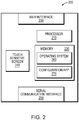
- Fig. 2 is a block diagram of an example mobile device 200.
- the mobile device 200 includes a processor 210, a memory 220, a wireless network interface 230, a touch-sensitive screen 240, a wired serial communication interface 250, as well as other hardware.
- the processor 210 includes logic configured to execute software and manipulate data from data structures.
- the memory 220 includes a plurality of storage locations for storing the software and the data structures.
- the wireless network interface 230 facilitates communication over a WLAN, or more specifically a Wi-Fi network.
- the touch-sensitive display screen 240 may receive user input in the form of gestures (e.g., touches, swipes, multi-touch gestures, etc.) from a user.
- the serial communication interface 250 may be a 30-pin dock interface, a Lightning interface, a USB interface, or another type of interface.
- An operating system 260 functionally organizes the mobile device 200.
- the operating system 260 may be an IOS® operating system available from Apple, Inc., an Android® operating system available from Google, Inc, or another type of operating system.
- a configuration app 270 is executed in conjunction with the operating system 260, to permit the mobile device 200 to operate in a configuration role, to configure a component (e.g., a controller, a user interface, or an endpoint) of the home automation system 100.
- the configuration app 270 may display a user interface on the touch sensitive screen 270, and receive user input thereon.
- a control app may also be stored in the memory 220 to permit the mobile device 200 to operate in a control role and control ongoing operation of the home automation system 100.
- the control app may also display its user interface on the touch sensitive screen 270, and receive user input thereon.
- a Wi-Fi enabled component of a home automation system 100 may not yet be configured with Wi-Fi settings needed to join the network. Further, the component may lack a display screen capable of providing a robust user interface for configuring these Wi-Fi settings, and other settings of the component.
- a user may configure the Wi-Fi and other settings.
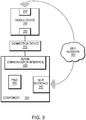
- Fig. 3 is a block diagram of an example mobile device 200 coupled via an example connection device 310 to an example component 320 (e.g., a controller, a user interface, or an endpoint) of a home automation system.
- the component includes a wired serial communication interface 330, a Wi-Fi Interface 340, as well as a Programmable System-on-Chip (PSoC) 350 that may support a programming environment.
- the connection device 310 couples the wired serial communication interface (e.g., 30-pin dock interface, Lightning interface, or USB interface, etc.) 250 of the mobile device 200 to the wired serial communication interface (e.g., a RS232 interface or other type of interface) 330 of the component 320.
- the connection device 310 may include hardware to support such a connection.
- connection device 310 may include a processor, an authentication chip, as well as other hardware (not shown).
- the connection device 310 may include a USB translation device as well as other hardware (not shown).
- the mobile device 200 may detect when it is connected to a component via the the connection device 320, and control commands may be passed from the mobile device 200 over the connection device 320 to configure a Wi-Fi interface 340 of the component so that the component may join the Wi-Fi network 370.
- control commands are sent over the connection device 320 to configure settings such as a network name (e.g., a service set identifier (SSID), a security type (e.g., Wired Equivalent Privacy (WEP), Wi-Fi Protected Access (WPA), etc.) a password (e.g., a SSID password), addresses (e.g., an Internet Protocol (IP) address of the component, a subnet mask, an IP address of a router, etc.) used to join the Wi-Fi network.
- SSID service set identifier
- WEP Wired Equivalent Privacy
- WPA Wi-Fi Protected Access
- addresses e.g., an Internet Protocol (IP) address of the component, a subnet mask, an IP address of a router, etc.
- IP Internet Protocol
- control commands are sent to at least configure the component's role or bindings and possibly controller settings, firmware, etc.
- a universal asynchronous receiver/transmitter (UART) protocol and related application program interface (API) supports the exchange of these control commands.
- the mobile device 200 may operate as a controller node, the connection device 310 may operate as a transparent middle node, and the component 330 may operate as a subordinate node.
- the mobile device 200 initially sends a common state packet over the connection device 310.
- the common state packet includes a UART pass-through command that instructs the connection device 310 to bridge communications.
- the connection device 310 determines a bus type of the interface the packet was received on, and detects the UART pass-through command.
- the connection device determines that the packet should be re-framed and sent out from a UART of the connection device 310 to the component 330.
- the packet is then received by the component 330.
- An acknowledgement packet may be sent back from the component 330 to the mobile device 200.
- the acknowledgment packet may include an uplink flag to indicate the direction of travel.
- the connection device 310 sees a packet with the uplink flag set, it may include a UART pass-through command in the packet, and then forward it onward to the mobile device 200.
- the UART pass-through command is used to distinguish between information originating at the connection device 200 and at the component 330.
- a communication channel is established between the mobile device 200 and component 330, usable when communication is not yet possible via the Wi-Fi network 370.
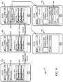
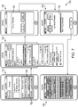
- Fig. 4 is a series of views 400 of an example mobile device 200, showing an example user interface on the touch sensitive display screen 240 while a connection device 310 and component 320 are being coupled to the mobile device.
- the connection device is still disconnected from the mobile device, and a status of "not connected" is indicated in a connected accessory display area 415.
- Other components accessible on the Wi-Fi network are indicated in Wi-Fi display area 417.
- the mobile device 200 detects when the connection device 310 is connected to it, and updates the view.
- the connection device 310 is now connected to the wired serial communication interface 250 of the mobile device, but not to the component 320.
- the connection device 310 is indicated in the connected accessory display area 415.
- the mobile device 200 detects when a component is connected to the connection device 310 and updates the view.
- the component 320 is now connected to the connection device 310.
- the component 310 here a controller having the model number "SSL-P018", is indicated in the connected accessory display area 415.
- the user has selected the connection device in the connected accessory display area 415, and additional information about the connection device 310 is shown.
- the user has selected the component in the connected accessory display area 415, and a main menu 460 for the component is shown. Using the main menu 460, the user may configure the component 320 to join the Wi-Fi network as well as configure additional settings of the component. When the component 320 has joined the Wi-Fi network, it may be shown in the Wi-Fi display area 417 of the views 410-430, for subsequent access.
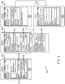
- Fig. 5 is a series of views 500 of an example mobile device 200, showing an example user interface while a user configures a component 320 to join a Wi-Fi network.
- a user may select an option 520 to configure the Wi-Fi settings of the component 320, and view 530 is then shown.
- view 530 the user interface shows a current Wi-Fi network that the mobile device 200 is connected to in area 532, and recently joined Wi-Fi networks in area 534.
- a network name, security, password, addresses and other information are already known by the mobile device 200. Still other accessible networks may be shown in area 536.
- a user may need to enter a network name, security, password, addresses and/or other information if one of these networks is desired, as shown in views 540 and 550. Addresses may also be entered using area 538 in view 530.
- the mobile device 200 sends control commands via the connection device 310 to the component 320 to configure the network name, security type, password, addresses, etc. to cause the component to join the Wi-Fi network. Once the component 320 has joined the Wi-Fi network, further control commands may be sent to the component 320 via the connection device 310 or via the now-accessible Wi-Fi network.
- Fig. 6 is a series of views 600 of an example mobile device 200, showing an example user interface while a user configures a role of a component 320 in the home automation system. From the main menu 460 shown in view 610, a user may select an option 620 to configure a role of the component 320, and an updated view 630 is shown. In view 630, various available roles for the component 320 are displayed in an area 640, and the user selects a desired role. In response to the user input, the mobile device 200 sends control commands to the component 320 to configure the role.
- Fig. 7 is a series of views 700 of an example mobile device 200, showing an example user interface while a user updates firmware of a component 320.
- a user may select an option 720 to configure firmware, and an updated view 730 is shown.
- view 730 various available firmwares, and versions thereof are shown.
- Firmware may be locally stored on the mobile device 200, or available in an online repository accessible by the mobile device 200.
- the user interface displays a confirmation prompt 740, as shown in view 750.
- the firmware is transferred from the mobile device 200 to the component 320.
- a status display 760 is presented as the firmware is transferred, as shown in view 770.
- a user may be able to cancel the transfer prior to its completion, as shown in view 780
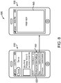
- Fig. 8 is a series of views 800 of an example mobile device 200, showing an example user interface while a user configures bindings and controller settings. From the main menu 460 shown in view 810, a user may select an option 820 to configure the bindings and controller settings. Upon selection, a web interface 840 displays controls for manipulating the bindings and controller settings, as shown in view 820. The web interface may be provided from the component 320 or another source, and the mobile device 200 may simply load and display webpages provided, without understanding their content.
- Fig. 9 is a flow chart of an example sequence of steps 900 to configure a component of a home automation system that is initially is inaccessible on a Wi-Fi network.
- the sequence of steps 900 may summarize aspects of the above discussed operation.
- a configuration app is executed on a mobile device.
- a user interface of the configuration app is displayed on a touch-sensitive display screen.
- a connection device is used to couple the mobile device to the component which is initially inaccessible on the Wi-Fi network.
- the connection device couples a wired serial communication interface of the mobile device to a wired serial communication of the component.
- the mobile device in response to input entered in the user interface being displayed on the touch-sensitive display screen, the mobile device sends control signals to the component via the connection device to configure Wi-Fi settings of the component, to cause the component join the Wi-Fi network.
- the mobile device in response to further input entered in the user interface being displayed on the touch-sensitive display screen, the mobile device sends additional control signals to the component via the connection device or the Wi-Fi network to configure additional settings of the now Wi-Fi accessible component.
- a software implementation may include computer-executable instructions stored in a non-transitory computer-readable medium, such as a volatile or persistent memory, a hard-disk, a compact disk (CD), or other tangible medium.
- a hardware implementation may include configured processors, logic circuits, application specific integrated circuits, and/or other types of hardware components.
- a combined software/hardware implementation may include both computer-executable instructions stored in a non-transitory computer-readable medium, as well as one or more hardware components, for example, processors, memories, etc. Accordingly, it should be understood that the above descriptions are meant to be taken only by way of example.
Claims (14)
- Procédé de configuration d'un composant (320) d'un système domotique qui est initialement inaccessible sur un réseau Wi-Fi, comprenant les étapes consistant à :exécuter une application de configuration, app, sur un dispositif mobile (200) présentant un écran d'affichage tactile, une interface utilisateur de l'application de configuration étant affichée à un utilisateur sur l'écran d'affichage tactile ;coupler le dispositif mobile (200) au composant (320) du système domotique via un dispositif de connexion (310), le dispositif de connexion connectant une interface de communication série câblée du dispositif mobile (250) à une interface de communication série câblée du composant (330) et étant capable de fonctionner comme un nœud intermédiaire transparent en réponse à un ordre de transfert d'émetteur-récepteur asynchrone universel, UART ;en réponse à une entrée saisie dans l'interface utilisateur affichée sur l'écran d'affichage tactile, envoyer des signaux de commande du dispositif mobile (200) au composant (320) via le dispositif de connexion (310) pour configurer des paramètres Wi-Fi du composant pour amener le composant à rejoindre le réseau Wi-Fi (370), les signaux de commande devant inclure l'ordre de transfert UART pour amener le dispositif de connexion à transférer les signaux de commande au composant (320) ;en réponse à une autre entrée saisie dans l'interface utilisateur affichée sur l'écran d'affichage tactile, envoyer des signaux de commande supplémentaires du dispositif mobile (200) au composant (320) via le dispositif de connexion (310) pour attribuer au composant un rôle dans le système domotique et/ou lier le composant (320), les signaux de commande supplémentaires devant inclure l'ordre de transfert UART pour amener le dispositif de connexion à transférer les signaux de commande au composant (320).
- Procédé selon la revendication 1, dans lequel l'étape consistant à envoyer des signaux de commande supplémentaires envoie des signaux de commande supplémentaires au composant (320) via le réseau Wi-Fi (370).
- Procédé selon la revendication 1, dans lequel le dispositif mobile (200) est un smartphone.
- Procédé selon la revendication 1, dans lequel l'interface de communication série câblée du dispositif mobile (250) est une interface Lightning et l'interface de communication série câblée du composant (330) est une interface RS232.
- Procédé selon la revendication 1, dans lequel l'interface de communication série câblée du dispositif mobile (250) est une interface Bus série universel, USB, et l'interface de communication série câblée du composant (330) est une interface RS232.
- Procédé selon la revendication 1, dans lequel le dispositif mobile (200) fonctionne comme un nœud de commande, le composant (320) fonctionne comme un nœud subordonné, les signaux de commande sont des paquets envoyés du nœud de commande au nœud intermédiaire transparent.
- Procédé selon la revendication 1, dans lequel le système domotique commande des dispositifs d'éclairage et le composant (320) est un dispositif de commande d'éclairage ou un clavier.
- Procédé selon la revendication 1, comprenant en outre les étapes consistant à :
exécuter une application de commande sur le dispositif mobile (200) ou un autre dispositif mobile, laquelle application de commande est configurée pour commander le fonctionnement en cours du système domotique après que les paramètres Wi-Fi et des paramètres supplémentaires du composant (320) ont été configurés. - Système de configuration d'un composant (320) d'un système domotique qui est initialement inaccessible sur un réseau Wi-Fi, comprenant :un dispositif mobile (200) présentant un processeur, une mémoire, une interface de communication série câblée (250) et un écran d'affichage tactile, dans lequel la mémoire est configurée pour stocker une application de configuration, app,l'écran d'affichage tactile est configuré pour afficher une interface utilisateur de l'application de configuration et le processeur est configuré pour exécuter l'application de configuration, et l'application de configuration, lorsqu'elle est exécutée, est configurée pour envoyer des signaux de commande par l'interface de communication série câblée en réponse à des entrées saisies dans l'interface utilisateur, les signaux de commande servant à configurer des paramètres Wi-Fi du composant du système domotique pour amener le composant à rejoindre le réseau Wi-Fi (370), les signaux de commande devant inclure un ordre de transfert d'émetteur/récepteur asynchrone universel, UART ; et un dispositif de connexion (310) couplé à l'interface de communication série câblée du dispositif mobile (250) et à une interface de communication série câblée du composant (330), le dispositif de connexion (310) étant configuré pour fonctionner comme un nœud intermédiaire transparent entre le dispositif mobile (200) et le composant (320) en réponse à l'ordre de transfert UART et pour propager les signaux de commande entre eux,dans lequel l'application de configuration, lorsqu'elle est exécutée, peut en outre être utilisée pour envoyer des signaux de commande supplémentaires au composant via le dispositif de connexion (310) pour attribuer au composant un rôle dans le système domotique et/ou lier le composant, les signaux de commande supplémentaires devant inclure l'ordre de transfert UART.
- Système selon la revendication 9, dans lequel le dispositif mobile (200) est un smartphone.
- Système selon la revendication 9, dans lequel l'interface de communication série câblée du dispositif mobile (250) est une interface Lightning et l'interface de communication série câblée du composant (330) est une interface RS232.
- Système selon la revendication 9, dans lequel l'interface de communication série câblée du dispositif mobile (250) est une interface Bus série universel, USB, et l'interface de communication série câblée du composant (330) est une interface RS232.
- Système selon la revendication 9, dans lequel le système domotique commande des dispositifs d'éclairage, le composant (320) un dispositif de commande d'éclairage ou un clavier.
- Système selon la revendication 9, dans lequel la mémoire du dispositif mobile (200) ou une mémoire d'un autre dispositif mobile est configurée pour stocker une application de commande, laquelle application de commande, lorsqu'elle est exécutée par le processeur du dispositif mobile ou un processeur de l'autre dispositif mobile, est configurée pour commander le fonctionnement en cours du système domotique après que les paramètres Wi-Fi et des paramètres supplémentaires du composant (320) ont été configurés.
Applications Claiming Priority (2)
| Application Number | Priority Date | Filing Date | Title |
|---|---|---|---|
| US13/923,826 US9736616B2 (en) | 2013-06-21 | 2013-06-21 | Configuration connection device |
| PCT/US2014/041474 WO2014204689A1 (fr) | 2013-06-21 | 2014-06-09 | Dispositif de connexion de configuration |
Publications (2)
| Publication Number | Publication Date |
|---|---|
| EP3011704A1 EP3011704A1 (fr) | 2016-04-27 |
| EP3011704B1 true EP3011704B1 (fr) | 2021-04-14 |
Family
ID=51134373
Family Applications (1)
| Application Number | Title | Priority Date | Filing Date |
|---|---|---|---|
| EP14736177.8A Active EP3011704B1 (fr) | 2013-06-21 | 2014-06-09 | Dispositif de connexion de configuration |
Country Status (10)
| Country | Link |
|---|---|
| US (1) | US9736616B2 (fr) |
| EP (1) | EP3011704B1 (fr) |
| JP (1) | JP6473743B2 (fr) |
| KR (1) | KR102225408B1 (fr) |
| CN (1) | CN105453486B (fr) |
| AU (2) | AU2014281083A1 (fr) |
| CA (1) | CA2916248C (fr) |
| ES (1) | ES2872400T3 (fr) |
| IL (1) | IL243256B (fr) |
| WO (1) | WO2014204689A1 (fr) |
Families Citing this family (12)
| Publication number | Priority date | Publication date | Assignee | Title |
|---|---|---|---|---|
| US9867260B2 (en) * | 2013-06-26 | 2018-01-09 | Savant Systems, Llc | Lighting controller |
| US9998326B2 (en) * | 2014-02-13 | 2018-06-12 | General Electric Company | Systems and methods for touch-less commissioning of intelligent electronic devices |
| US9754090B2 (en) * | 2014-05-07 | 2017-09-05 | Vivint, Inc. | Setting up a system with a mobile device |
| US10032364B2 (en) * | 2014-05-15 | 2018-07-24 | Savant Systems, Llc | Standalone wireless lighting application |
| CN105446471A (zh) * | 2014-09-02 | 2016-03-30 | 昆盈企业股份有限公司 | 周边输入装置与其设定方法 |
| US10205626B2 (en) * | 2014-12-29 | 2019-02-12 | International Business Machines Corporation | Systems and methods for online purchases of integrated services |
| CN104812131B (zh) * | 2015-04-14 | 2018-12-18 | 周贤和 | 一种智能的电器控制系统 |
| US9806900B2 (en) * | 2015-10-05 | 2017-10-31 | Savant Systems, Llc | Wireless provisioning and configuring of hardware elements of a home automation system |
| US10594627B2 (en) | 2016-01-27 | 2020-03-17 | Oracle International Corporation | System and method for supporting scalable representation of switch port status in a high performance computing environment |
| CN107205239B (zh) * | 2017-05-26 | 2020-06-16 | 广东美的厨房电器制造有限公司 | 一种检测无线网连接的方法及检测设备 |
| US10292089B2 (en) * | 2017-09-18 | 2019-05-14 | Sonos, Inc. | Re-establishing connectivity on lost players |
| CN109981747B (zh) * | 2019-03-04 | 2022-06-03 | 深圳绿米联创科技有限公司 | 设备控制方法、装置、电子设备及存储介质 |
Family Cites Families (24)
| Publication number | Priority date | Publication date | Assignee | Title |
|---|---|---|---|---|
| JP2002236561A (ja) * | 2001-02-07 | 2002-08-23 | Nec Corp | 無線lanプリンタ機器の設定装置 |
| JP5054129B2 (ja) * | 2003-06-20 | 2012-10-24 | キヤノン株式会社 | 情報処理装置及びその制御方法、並びにプログラム |
| US7490350B1 (en) * | 2004-03-12 | 2009-02-10 | Sca Technica, Inc. | Achieving high assurance connectivity on computing devices and defeating blended hacking attacks |
| US7757010B2 (en) * | 2006-04-28 | 2010-07-13 | Mediatek Inc. | Systems and methods for managing mass storage devices in electronic devices |
| GB2438224A (en) * | 2006-05-17 | 2007-11-21 | Plamen Spassov Vassilev | Automatic Bathtub Filler and Circulation system |
| US20130150004A1 (en) * | 2006-08-11 | 2013-06-13 | Michael Rosen | Method and apparatus for reducing mobile phone usage while driving |
| US8254352B2 (en) * | 2007-06-28 | 2012-08-28 | Universal Electronics Inc. | System and method for configuration of network-capable appliances |
| TW200952536A (en) * | 2008-06-11 | 2009-12-16 | Asustek Comp Inc | Wireless device and method for automatically establishing wireless connection |
| WO2010063001A1 (fr) * | 2008-11-26 | 2010-06-03 | Wireless Environment, Llc | Dispositifs d’éclairage sans fil et applications associées |
| RU2545025C2 (ru) * | 2009-07-24 | 2015-03-27 | Конинклейке Филипс Электроникс Н.В. | Система освещения и способ определения энергопотребления картин освещения системы освещения |
| WO2012018526A1 (fr) * | 2010-07-26 | 2012-02-09 | Lightwaves Systems, Inc. | Système de transport de données amélioré à grande largeur de bande utilisé dans un réseau électrique intelligent (sg) |
| US8918219B2 (en) * | 2010-11-19 | 2014-12-23 | Google Inc. | User friendly interface for control unit |
| US8719581B2 (en) * | 2010-09-22 | 2014-05-06 | Savant Systems, Llc | Programmable multimedia controller with flexible user access and shared device configurations |
| US8583040B2 (en) * | 2010-10-01 | 2013-11-12 | Digi International Inc. | Devices, systems, and methods for configuring a wireless device |
| JP5177460B2 (ja) * | 2010-12-10 | 2013-04-03 | ブラザー工業株式会社 | 情報処理システム |
| JP5565362B2 (ja) * | 2011-03-30 | 2014-08-06 | ブラザー工業株式会社 | 制御装置 |
| US20120306621A1 (en) * | 2011-06-03 | 2012-12-06 | Leviton Manufacturing Co., Inc. | Lighting control network configuration with rfid devices |
| WO2013003813A1 (fr) | 2011-06-30 | 2013-01-03 | Lutron Electronics Co., Inc. | Dispositif et procédé permettant de transmettre de façon optique des informations numériques à partir d'un smart phone vers un dispositif de commande de charge |
| US10271407B2 (en) * | 2011-06-30 | 2019-04-23 | Lutron Electronics Co., Inc. | Load control device having Internet connectivity |
| WO2013003804A2 (fr) * | 2011-06-30 | 2013-01-03 | Lutron Electronics Co., Inc. | Procédé de programmation de dispositif de régulation de charge à l'aide de téléphone intelligent |
| JP2013055463A (ja) * | 2011-09-02 | 2013-03-21 | Canon Inc | 無線設定制御装置、その制御方法、および制御プログラム |
| CA2890612A1 (fr) | 2011-11-07 | 2013-05-16 | Kortek Industries Pty Ltd | Systeme adaptable d'alimentation, d'eclairage et d'automatisation sans fil |
| US9134493B2 (en) * | 2012-03-07 | 2015-09-15 | Celerity Technologies Inc. | Fiber optic cable with electrical connectors at both ends |
| US9488994B2 (en) * | 2012-03-29 | 2016-11-08 | Honeywell International Inc. | Method and system for configuring wireless sensors in an HVAC system |
-
2013
- 2013-06-21 US US13/923,826 patent/US9736616B2/en active Active
-
2014
- 2014-06-09 KR KR1020167001843A patent/KR102225408B1/ko active IP Right Grant
- 2014-06-09 CA CA2916248A patent/CA2916248C/fr active Active
- 2014-06-09 EP EP14736177.8A patent/EP3011704B1/fr active Active
- 2014-06-09 JP JP2016521437A patent/JP6473743B2/ja active Active
- 2014-06-09 CN CN201480045939.8A patent/CN105453486B/zh active Active
- 2014-06-09 AU AU2014281083A patent/AU2014281083A1/en not_active Abandoned
- 2014-06-09 ES ES14736177T patent/ES2872400T3/es active Active
- 2014-06-09 WO PCT/US2014/041474 patent/WO2014204689A1/fr active Application Filing
-
2015
- 2015-12-21 IL IL243256A patent/IL243256B/en active IP Right Grant
-
2018
- 2018-05-04 AU AU2018203123A patent/AU2018203123B2/en active Active
Non-Patent Citations (1)
| Title |
|---|
| None * |
Also Published As
| Publication number | Publication date |
|---|---|
| AU2018203123A1 (en) | 2018-05-24 |
| JP2016524422A (ja) | 2016-08-12 |
| CA2916248A1 (fr) | 2014-12-24 |
| IL243256B (en) | 2019-12-31 |
| WO2014204689A1 (fr) | 2014-12-24 |
| CA2916248C (fr) | 2023-01-17 |
| IL243256A0 (en) | 2016-02-29 |
| AU2018203123B2 (en) | 2019-03-14 |
| KR102225408B1 (ko) | 2021-03-08 |
| US9736616B2 (en) | 2017-08-15 |
| KR20160024386A (ko) | 2016-03-04 |
| CN105453486A (zh) | 2016-03-30 |
| AU2014281083A1 (en) | 2016-01-21 |
| US20140376528A1 (en) | 2014-12-25 |
| CN105453486B (zh) | 2019-06-07 |
| JP6473743B2 (ja) | 2019-02-20 |
| EP3011704A1 (fr) | 2016-04-27 |
| ES2872400T3 (es) | 2021-11-02 |
Similar Documents
| Publication | Publication Date | Title |
|---|---|---|
| AU2018203123B2 (en) | A configuration connection device | |
| US10931470B1 (en) | Thermostat synchronization via remote input device | |
| KR102350430B1 (ko) | 홈 오토메이션 시스템의 하드웨어 엘리먼트들의 무선 프로비저닝 및 구성 | |
| EP3014593B1 (fr) | Système de commande d'éclairage | |
| TWI488463B (zh) | 智慧閘道、智慧家居系統及家電設備的智慧控制方法 | |
| US20150280935A1 (en) | Thermostat code input system and method therefor | |
| CN112789828A (zh) | 局域网中的遥控器功能的智能适配 | |
| CN108702315B (zh) | 在连接到不同网络的两个本地设备之间建立连接 | |
| KR101590746B1 (ko) | 전자 장치의 네트워크 연결 설정 장치 및 방법 | |
| JP6150516B2 (ja) | 施設管理システム、携帯端末、施設管理装置および施設管理方法 | |
| KR101333656B1 (ko) | 근접 통신을 이용한 건물 자동화 시스템 | |
| US20210204128A1 (en) | End user inclusion and access of devices | |
| KR20160126787A (ko) | 근거리 무선 통신 허브 및 이를 이용한 원격 제어 시스템 |
Legal Events
| Date | Code | Title | Description |
|---|---|---|---|
| PUAI | Public reference made under article 153(3) epc to a published international application that has entered the european phase |
Free format text: ORIGINAL CODE: 0009012 |
|
| 17P | Request for examination filed |
Effective date: 20151218 |
|
| AK | Designated contracting states |
Kind code of ref document: A1 Designated state(s): AL AT BE BG CH CY CZ DE DK EE ES FI FR GB GR HR HU IE IS IT LI LT LU LV MC MK MT NL NO PL PT RO RS SE SI SK SM TR |
|
| AX | Request for extension of the european patent |
Extension state: BA ME |
|
| DAX | Request for extension of the european patent (deleted) | ||
| STAA | Information on the status of an ep patent application or granted ep patent |
Free format text: STATUS: EXAMINATION IS IN PROGRESS |
|
| 17Q | First examination report despatched |
Effective date: 20180118 |
|
| RAP1 | Party data changed (applicant data changed or rights of an application transferred) |
Owner name: SAVANT SYSTEMS, INC. |
|
| REG | Reference to a national code |
Ref country code: DE Ref legal event code: R079 Ref document number: 602014076568 Country of ref document: DE Free format text: PREVIOUS MAIN CLASS: H04L0012280000 Ipc: H04L0012240000 |
|
| GRAP | Despatch of communication of intention to grant a patent |
Free format text: ORIGINAL CODE: EPIDOSNIGR1 |
|
| STAA | Information on the status of an ep patent application or granted ep patent |
Free format text: STATUS: GRANT OF PATENT IS INTENDED |
|
| RIC1 | Information provided on ipc code assigned before grant |
Ipc: H04W 4/50 20180101ALI20201130BHEP Ipc: H05B 47/19 20200101ALI20201130BHEP Ipc: H04L 12/24 20060101AFI20201130BHEP Ipc: H04L 12/28 20060101ALI20201130BHEP Ipc: H04W 84/12 20090101ALI20201130BHEP Ipc: H04W 12/00 20090101ALI20201130BHEP Ipc: H04W 12/04 20090101ALI20201130BHEP |
|
| INTG | Intention to grant announced |
Effective date: 20201215 |
|
| GRAS | Grant fee paid |
Free format text: ORIGINAL CODE: EPIDOSNIGR3 |
|
| GRAA | (expected) grant |
Free format text: ORIGINAL CODE: 0009210 |
|
| STAA | Information on the status of an ep patent application or granted ep patent |
Free format text: STATUS: THE PATENT HAS BEEN GRANTED |
|
| AK | Designated contracting states |
Kind code of ref document: B1 Designated state(s): AL AT BE BG CH CY CZ DE DK EE ES FI FR GB GR HR HU IE IS IT LI LT LU LV MC MK MT NL NO PL PT RO RS SE SI SK SM TR |
|
| REG | Reference to a national code |
Ref country code: GB Ref legal event code: FG4D |
|
| REG | Reference to a national code |
Ref country code: CH Ref legal event code: EP |
|
| REG | Reference to a national code |
Ref country code: DE Ref legal event code: R096 Ref document number: 602014076568 Country of ref document: DE |
|
| REG | Reference to a national code |
Ref country code: IE Ref legal event code: FG4D |
|
| REG | Reference to a national code |
Ref country code: AT Ref legal event code: REF Ref document number: 1383436 Country of ref document: AT Kind code of ref document: T Effective date: 20210515 |
|
| REG | Reference to a national code |
Ref country code: LT Ref legal event code: MG9D |
|
| REG | Reference to a national code |
Ref country code: AT Ref legal event code: MK05 Ref document number: 1383436 Country of ref document: AT Kind code of ref document: T Effective date: 20210414 |
|
| REG | Reference to a national code |
Ref country code: NL Ref legal event code: MP Effective date: 20210414 |
|
| PG25 | Lapsed in a contracting state [announced via postgrant information from national office to epo] |
Ref country code: AT Free format text: LAPSE BECAUSE OF FAILURE TO SUBMIT A TRANSLATION OF THE DESCRIPTION OR TO PAY THE FEE WITHIN THE PRESCRIBED TIME-LIMIT Effective date: 20210414 Ref country code: BG Free format text: LAPSE BECAUSE OF FAILURE TO SUBMIT A TRANSLATION OF THE DESCRIPTION OR TO PAY THE FEE WITHIN THE PRESCRIBED TIME-LIMIT Effective date: 20210714 Ref country code: NL Free format text: LAPSE BECAUSE OF FAILURE TO SUBMIT A TRANSLATION OF THE DESCRIPTION OR TO PAY THE FEE WITHIN THE PRESCRIBED TIME-LIMIT Effective date: 20210414 Ref country code: LT Free format text: LAPSE BECAUSE OF FAILURE TO SUBMIT A TRANSLATION OF THE DESCRIPTION OR TO PAY THE FEE WITHIN THE PRESCRIBED TIME-LIMIT Effective date: 20210414 Ref country code: FI Free format text: LAPSE BECAUSE OF FAILURE TO SUBMIT A TRANSLATION OF THE DESCRIPTION OR TO PAY THE FEE WITHIN THE PRESCRIBED TIME-LIMIT Effective date: 20210414 Ref country code: HR Free format text: LAPSE BECAUSE OF FAILURE TO SUBMIT A TRANSLATION OF THE DESCRIPTION OR TO PAY THE FEE WITHIN THE PRESCRIBED TIME-LIMIT Effective date: 20210414 |
|
| REG | Reference to a national code |
Ref country code: ES Ref legal event code: FG2A Ref document number: 2872400 Country of ref document: ES Kind code of ref document: T3 Effective date: 20211102 |
|
| REG | Reference to a national code |
Ref country code: DE Ref legal event code: R079 Ref document number: 602014076568 Country of ref document: DE Free format text: PREVIOUS MAIN CLASS: H04L0012240000 Ipc: H04L0041000000 |
|
| PG25 | Lapsed in a contracting state [announced via postgrant information from national office to epo] |
Ref country code: NO Free format text: LAPSE BECAUSE OF FAILURE TO SUBMIT A TRANSLATION OF THE DESCRIPTION OR TO PAY THE FEE WITHIN THE PRESCRIBED TIME-LIMIT Effective date: 20210714 Ref country code: PT Free format text: LAPSE BECAUSE OF FAILURE TO SUBMIT A TRANSLATION OF THE DESCRIPTION OR TO PAY THE FEE WITHIN THE PRESCRIBED TIME-LIMIT Effective date: 20210816 Ref country code: PL Free format text: LAPSE BECAUSE OF FAILURE TO SUBMIT A TRANSLATION OF THE DESCRIPTION OR TO PAY THE FEE WITHIN THE PRESCRIBED TIME-LIMIT Effective date: 20210414 Ref country code: SE Free format text: LAPSE BECAUSE OF FAILURE TO SUBMIT A TRANSLATION OF THE DESCRIPTION OR TO PAY THE FEE WITHIN THE PRESCRIBED TIME-LIMIT Effective date: 20210414 Ref country code: RS Free format text: LAPSE BECAUSE OF FAILURE TO SUBMIT A TRANSLATION OF THE DESCRIPTION OR TO PAY THE FEE WITHIN THE PRESCRIBED TIME-LIMIT Effective date: 20210414 Ref country code: LV Free format text: LAPSE BECAUSE OF FAILURE TO SUBMIT A TRANSLATION OF THE DESCRIPTION OR TO PAY THE FEE WITHIN THE PRESCRIBED TIME-LIMIT Effective date: 20210414 Ref country code: IS Free format text: LAPSE BECAUSE OF FAILURE TO SUBMIT A TRANSLATION OF THE DESCRIPTION OR TO PAY THE FEE WITHIN THE PRESCRIBED TIME-LIMIT Effective date: 20210814 Ref country code: GR Free format text: LAPSE BECAUSE OF FAILURE TO SUBMIT A TRANSLATION OF THE DESCRIPTION OR TO PAY THE FEE WITHIN THE PRESCRIBED TIME-LIMIT Effective date: 20210715 |
|
| REG | Reference to a national code |
Ref country code: DE Ref legal event code: R097 Ref document number: 602014076568 Country of ref document: DE |
|
| PG25 | Lapsed in a contracting state [announced via postgrant information from national office to epo] |
Ref country code: DK Free format text: LAPSE BECAUSE OF FAILURE TO SUBMIT A TRANSLATION OF THE DESCRIPTION OR TO PAY THE FEE WITHIN THE PRESCRIBED TIME-LIMIT Effective date: 20210414 Ref country code: EE Free format text: LAPSE BECAUSE OF FAILURE TO SUBMIT A TRANSLATION OF THE DESCRIPTION OR TO PAY THE FEE WITHIN THE PRESCRIBED TIME-LIMIT Effective date: 20210414 Ref country code: CZ Free format text: LAPSE BECAUSE OF FAILURE TO SUBMIT A TRANSLATION OF THE DESCRIPTION OR TO PAY THE FEE WITHIN THE PRESCRIBED TIME-LIMIT Effective date: 20210414 Ref country code: SK Free format text: LAPSE BECAUSE OF FAILURE TO SUBMIT A TRANSLATION OF THE DESCRIPTION OR TO PAY THE FEE WITHIN THE PRESCRIBED TIME-LIMIT Effective date: 20210414 Ref country code: SM Free format text: LAPSE BECAUSE OF FAILURE TO SUBMIT A TRANSLATION OF THE DESCRIPTION OR TO PAY THE FEE WITHIN THE PRESCRIBED TIME-LIMIT Effective date: 20210414 Ref country code: RO Free format text: LAPSE BECAUSE OF FAILURE TO SUBMIT A TRANSLATION OF THE DESCRIPTION OR TO PAY THE FEE WITHIN THE PRESCRIBED TIME-LIMIT Effective date: 20210414 Ref country code: MC Free format text: LAPSE BECAUSE OF FAILURE TO SUBMIT A TRANSLATION OF THE DESCRIPTION OR TO PAY THE FEE WITHIN THE PRESCRIBED TIME-LIMIT Effective date: 20210414 |
|
| REG | Reference to a national code |
Ref country code: CH Ref legal event code: PL |
|
| PLBE | No opposition filed within time limit |
Free format text: ORIGINAL CODE: 0009261 |
|
| STAA | Information on the status of an ep patent application or granted ep patent |
Free format text: STATUS: NO OPPOSITION FILED WITHIN TIME LIMIT |
|
| REG | Reference to a national code |
Ref country code: BE Ref legal event code: MM Effective date: 20210630 |
|
| 26N | No opposition filed |
Effective date: 20220117 |
|
| PG25 | Lapsed in a contracting state [announced via postgrant information from national office to epo] |
Ref country code: LU Free format text: LAPSE BECAUSE OF NON-PAYMENT OF DUE FEES Effective date: 20210609 |
|
| PG25 | Lapsed in a contracting state [announced via postgrant information from national office to epo] |
Ref country code: LI Free format text: LAPSE BECAUSE OF NON-PAYMENT OF DUE FEES Effective date: 20210630 Ref country code: IE Free format text: LAPSE BECAUSE OF NON-PAYMENT OF DUE FEES Effective date: 20210609 Ref country code: CH Free format text: LAPSE BECAUSE OF NON-PAYMENT OF DUE FEES Effective date: 20210630 |
|
| PG25 | Lapsed in a contracting state [announced via postgrant information from national office to epo] |
Ref country code: IS Free format text: LAPSE BECAUSE OF FAILURE TO SUBMIT A TRANSLATION OF THE DESCRIPTION OR TO PAY THE FEE WITHIN THE PRESCRIBED TIME-LIMIT Effective date: 20210814 Ref country code: AL Free format text: LAPSE BECAUSE OF FAILURE TO SUBMIT A TRANSLATION OF THE DESCRIPTION OR TO PAY THE FEE WITHIN THE PRESCRIBED TIME-LIMIT Effective date: 20210414 |
|
| PG25 | Lapsed in a contracting state [announced via postgrant information from national office to epo] |
Ref country code: BE Free format text: LAPSE BECAUSE OF NON-PAYMENT OF DUE FEES Effective date: 20210630 |
|
| PG25 | Lapsed in a contracting state [announced via postgrant information from national office to epo] |
Ref country code: HU Free format text: LAPSE BECAUSE OF FAILURE TO SUBMIT A TRANSLATION OF THE DESCRIPTION OR TO PAY THE FEE WITHIN THE PRESCRIBED TIME-LIMIT; INVALID AB INITIO Effective date: 20140609 |
|
| PG25 | Lapsed in a contracting state [announced via postgrant information from national office to epo] |
Ref country code: CY Free format text: LAPSE BECAUSE OF FAILURE TO SUBMIT A TRANSLATION OF THE DESCRIPTION OR TO PAY THE FEE WITHIN THE PRESCRIBED TIME-LIMIT Effective date: 20210414 |
|
| P01 | Opt-out of the competence of the unified patent court (upc) registered |
Effective date: 20230531 |
|
| PGFP | Annual fee paid to national office [announced via postgrant information from national office to epo] |
Ref country code: FR Payment date: 20230626 Year of fee payment: 10 Ref country code: DE Payment date: 20230626 Year of fee payment: 10 |
|
| PGFP | Annual fee paid to national office [announced via postgrant information from national office to epo] |
Ref country code: IT Payment date: 20230620 Year of fee payment: 10 Ref country code: GB Payment date: 20230627 Year of fee payment: 10 Ref country code: ES Payment date: 20230703 Year of fee payment: 10 |