EP3011704B1 - A configuration connection device - Google Patents
A configuration connection device Download PDFInfo
- Publication number
- EP3011704B1 EP3011704B1 EP14736177.8A EP14736177A EP3011704B1 EP 3011704 B1 EP3011704 B1 EP 3011704B1 EP 14736177 A EP14736177 A EP 14736177A EP 3011704 B1 EP3011704 B1 EP 3011704B1
- Authority
- EP
- European Patent Office
- Prior art keywords
- component
- mobile device
- interface
- serial communication
- control signals
- Prior art date
- Legal status (The legal status is an assumption and is not a legal conclusion. Google has not performed a legal analysis and makes no representation as to the accuracy of the status listed.)
- Active
Links
Images


Classifications
-
- H—ELECTRICITY
- H04—ELECTRIC COMMUNICATION TECHNIQUE
- H04W—WIRELESS COMMUNICATION NETWORKS
- H04W4/00—Services specially adapted for wireless communication networks; Facilities therefor
- H04W4/50—Service provisioning or reconfiguring
-
- H—ELECTRICITY
- H04—ELECTRIC COMMUNICATION TECHNIQUE
- H04L—TRANSMISSION OF DIGITAL INFORMATION, e.g. TELEGRAPHIC COMMUNICATION
- H04L12/00—Data switching networks
- H04L12/28—Data switching networks characterised by path configuration, e.g. LAN [Local Area Networks] or WAN [Wide Area Networks]
- H04L12/2803—Home automation networks
- H04L12/2807—Exchanging configuration information on appliance services in a home automation network
- H04L12/2814—Exchanging control software or macros for controlling appliance services in a home automation network
-
- H—ELECTRICITY
- H04—ELECTRIC COMMUNICATION TECHNIQUE
- H04L—TRANSMISSION OF DIGITAL INFORMATION, e.g. TELEGRAPHIC COMMUNICATION
- H04L41/00—Arrangements for maintenance, administration or management of data switching networks, e.g. of packet switching networks
- H04L41/26—Arrangements for maintenance, administration or management of data switching networks, e.g. of packet switching networks using dedicated tools for LAN [Local Area Network] management
-
- H—ELECTRICITY
- H04—ELECTRIC COMMUNICATION TECHNIQUE
- H04W—WIRELESS COMMUNICATION NETWORKS
- H04W12/00—Security arrangements; Authentication; Protecting privacy or anonymity
- H04W12/04—Key management, e.g. using generic bootstrapping architecture [GBA]
- H04W12/047—Key management, e.g. using generic bootstrapping architecture [GBA] without using a trusted network node as an anchor
- H04W12/0471—Key exchange
-
- H—ELECTRICITY
- H04—ELECTRIC COMMUNICATION TECHNIQUE
- H04W—WIRELESS COMMUNICATION NETWORKS
- H04W12/00—Security arrangements; Authentication; Protecting privacy or anonymity
- H04W12/50—Secure pairing of devices
-
- H—ELECTRICITY
- H05—ELECTRIC TECHNIQUES NOT OTHERWISE PROVIDED FOR
- H05B—ELECTRIC HEATING; ELECTRIC LIGHT SOURCES NOT OTHERWISE PROVIDED FOR; CIRCUIT ARRANGEMENTS FOR ELECTRIC LIGHT SOURCES, IN GENERAL
- H05B47/00—Circuit arrangements for operating light sources in general, i.e. where the type of light source is not relevant
- H05B47/10—Controlling the light source
- H05B47/175—Controlling the light source by remote control
- H05B47/19—Controlling the light source by remote control via wireless transmission
-
- H—ELECTRICITY
- H04—ELECTRIC COMMUNICATION TECHNIQUE
- H04L—TRANSMISSION OF DIGITAL INFORMATION, e.g. TELEGRAPHIC COMMUNICATION
- H04L12/00—Data switching networks
- H04L12/28—Data switching networks characterised by path configuration, e.g. LAN [Local Area Networks] or WAN [Wide Area Networks]
- H04L12/2803—Home automation networks
- H04L2012/284—Home automation networks characterised by the type of medium used
- H04L2012/2841—Wireless
-
- H—ELECTRICITY
- H04—ELECTRIC COMMUNICATION TECHNIQUE
- H04L—TRANSMISSION OF DIGITAL INFORMATION, e.g. TELEGRAPHIC COMMUNICATION
- H04L12/00—Data switching networks
- H04L12/28—Data switching networks characterised by path configuration, e.g. LAN [Local Area Networks] or WAN [Wide Area Networks]
- H04L12/2803—Home automation networks
- H04L2012/2847—Home automation networks characterised by the type of home appliance used
- H04L2012/285—Generic home appliances, e.g. refrigerators
-
- H—ELECTRICITY
- H04—ELECTRIC COMMUNICATION TECHNIQUE
- H04W—WIRELESS COMMUNICATION NETWORKS
- H04W84/00—Network topologies
- H04W84/02—Hierarchically pre-organised networks, e.g. paging networks, cellular networks, WLAN [Wireless Local Area Network] or WLL [Wireless Local Loop]
- H04W84/10—Small scale networks; Flat hierarchical networks
- H04W84/12—WLAN [Wireless Local Area Networks]
Definitions
- the present disclosure relates generally to home automation systems and more specifically to a connection device for configuring components of a home automation system that are initially inaccessible on a Wi-Fi network.
- controllers In a typical home automation system, one or more controllers organize the system. The controllers operates under directions from a user, received on user interface devices in communication with the controllers. The controllers may control endpoints that implement functions to change the environment, and in some cases collect environmental data. Depending on the type of home automation system, the nature of the controllers, user interface devices, and endpoints may vary. Further, the same device may sometimes operate as both a controller, a user interface device, and/or an endpoint, depending on its capabilities and current role. As used herein, the term "component” should be understood to refer generally to controllers, user interface devices, and/or endpoints of a home automation system.
- a home automation system may include components related to any of a variety of different types of functions in the areas of lighting, climate control, audio/video, window shades and drapes, security and surveillance, communications, entry control, power management, and the like.
- controllers may include a lighting controller
- user interface devices may include one or more remote controls and keypads
- endpoints may include load modules.
- the controllers may include one or more heating ventilation and air conditioning (HVAC) controllers (or HVAC control functionality integrated into general purpose controllers)
- the user interface devices may include one or more remote controls
- the endpoints may include one or more thermostats, sensors, and the like.
- HVAC heating ventilation and air conditioning
- Wi-Fi network refers to a WLAN that is based on one or more of the Institute of Electrical and Electronics Engineers (IEEE) 802.11 standards.
- IEEE Institute of Electrical and Electronics Engineers
- a Wi-Fi network may be used to pass control commands among the components to support ongoing home automation functions.
- the patent application document WO2013/067569A1 discloses a power control device for controlling an electrical apparatus through a wireless communications link such as a Wi-Fi Direct peer-to-peer communications link, with a personal controller (e.g. smartphone), to control a supply of electricity to the electrical apparatus in domestic and commercial applications.
- wireless networking circuitry may be readily integrated into components, configuring such components to join a Wi-Fi network and properly interact with one another may present challenges. Before a component has joined a Wi-Fi network, it may be inaccessible to other components via Wi-Fi communication.
- a component In order to join a Wi-Fi network, a component typically must be configured with Wi-Fi settings, for example, a network name (e.g., service set identifier (SSID)), a security type (e.g., Wired Equivalent Privacy (WEP), Wi-Fi Protected Access (WPA) a password, addresses (e.g., an Internet Protocol (IP) address, a subnet mask, an IP address of a gateway/router), etc.
- the component may need to have its role defined, have its firmware updated, and/or be configured with bindings and controller setting, before it can properly interact with other components.
- Patent application US2009/003240A1 discloses a method for using a controlling device e.g. a remote control for configuring an appliance for use in a WiFi network. Information required to perform communication on the wireless local area network is obtained from a user through a setup wizard.
- a component for example, a lighting controller, a keypad, etc., may lack any sort of display screen that could show such a user interface. Users may be required to undertake cumbersome and inefficient means to configure components.
- a connection device couples a mobile device having a touch-sensitive display screen to a component (e.g., a controller, a user interface, or an endpoint) of a home automation system.
- the connection device couples a wired serial communication interface of the mobile device (e.g., a 30-pin dock interface, Lightning interface, Universal Serial Bus (USB) interface, etc.) to a wired serial communication interface (e.g., an RS232 interface or other type of interface) of the component of the home automation system.
- An authentication chip, processor, or other circuitry may be included internal to the connection device, and facilitate communication between the wired serial communication interfaces.
- the mobile device executes a configuration application (app), whose user interface is displayed on the touch-sensitive display screen.
- a user may configure the component to join a Wi-Fi network, as well as configure more advanced settings of the component.
- the configuration app on the mobile device may send control commands via the connection device to the component, to set a network name, a security type, a password, addresses, etc., to cause the component to join aWi-Fi network.
- the configuration app on the mobile device may send additional control commands via the connection device, or the Wi-Fi network, to the component to configure additional settings (e.g., a role, firmware, bindings and controller settings, etc.) of the component.
- additional settings e.g., a role, firmware, bindings and controller settings, etc.
- Fig. 1 is a block diagram of an architecture of an example home automation system 100 that focuses on lighting control.
- the focus on lighting control is merely illustrative, and it should be understood that a home automation system may support a variety of different types of functions relating to lighting, climate control, audio/video, window shades and drapes, security and surveillance, communications, entry control, power management, and the like, and that the descriptions below are not limited to lighting control.
- a home automation system may be devoted to one of these functions, or a combination of multiple ones of these functions.
- a home automation system may be deployed in a residential home and the functions adapted to a residential environment. Alternatively, a home automation system may be deployed in a commercial building (such as an office building, store, factory, etc.) and these functions adapted to commercial requirements.
- the example home automation system 100 is composed of a number of home automation components (e.g., controllers, a user interfaces, and endpoints) related to lighting control.
- the controllers include a lighting controller 110 and a host controller 120.
- the user interfaces include keypads 170, remote controls 175, and potentially mobile devices 200.
- the endpoint units include load modules, lamp modules (not shown), and the like.
- the lighting controller 110 provides control and communication functionality, and supports, via a module bus 130, the load modules 140.
- the load modules include dimmer modules and relay modules that dim and/or switch individual lighting devices, when directed to do so by the lighting controller 110.
- the lighting controller 110 supports, via a module bus 130, keypad link units 150 that are coupled, via a respective station bus 160, to keypads 170.
- the keypads 170 receive user input indicating lighting devices to dim and/or switch, which is provided back to the lighting controller 110.
- the lighting controller 110 is coupled, via a wired local area network (LAN) 180 to the host controller 120.
- the host controller 120 is configured to control and monitor operations of the lighting controller 110, as well as to provide user interface interpretation and high-level control functions.
- One or more wireless access points 190 are coupled to the LAN 180, and support a WLAN, or more specifically, a Wi-Fi network.
- the Wi-Fi network is utilized by remote controls 175, and mobile devices 200.
- one or more other components of the home automation system 100 may utilize the Wi-Fi network.
- the lighting controller 110, keypads 170 and other components may be Wi-Fi enabled, and use the Wi-Fi network to supplement, or (alternatively) in place of, wired connections.
- mobile devices 200 may be used to configure components of the home automation system 100. Each individual mobile device 200 may be used in one or both of these roles.
- the term "mobile device” refers to an electronic device that is adapted to be transported on one's person and includes a wireless communication interface and a touch sensitive display screen. Devices such as tablet computers (e.g., the iPad® tablet available from Apple, Inc.), smartphones (e.g., the iPhone® smartphones available from Apple, Inc., and Android® smartphones available from various suppliers), and certain portable media players (e.g., such as the iPod® touch available from Apple, Inc.), are considered mobile devices. A desktop computer would not be considered a mobile device.
- a mobile device 200 may execute a control application (app) and communicate with the host controller 120.
- a configuration app When used in a configuration role, a mobile device 200 may execute a configuration app and communicate directly with individual non-controller components.
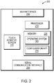
- Fig. 2 is a block diagram of an example mobile device 200.
- the mobile device 200 includes a processor 210, a memory 220, a wireless network interface 230, a touch-sensitive screen 240, a wired serial communication interface 250, as well as other hardware.
- the processor 210 includes logic configured to execute software and manipulate data from data structures.
- the memory 220 includes a plurality of storage locations for storing the software and the data structures.
- the wireless network interface 230 facilitates communication over a WLAN, or more specifically a Wi-Fi network.
- the touch-sensitive display screen 240 may receive user input in the form of gestures (e.g., touches, swipes, multi-touch gestures, etc.) from a user.
- the serial communication interface 250 may be a 30-pin dock interface, a Lightning interface, a USB interface, or another type of interface.
- An operating system 260 functionally organizes the mobile device 200.
- the operating system 260 may be an IOS® operating system available from Apple, Inc., an Android® operating system available from Google, Inc, or another type of operating system.
- a configuration app 270 is executed in conjunction with the operating system 260, to permit the mobile device 200 to operate in a configuration role, to configure a component (e.g., a controller, a user interface, or an endpoint) of the home automation system 100.
- the configuration app 270 may display a user interface on the touch sensitive screen 270, and receive user input thereon.
- a control app may also be stored in the memory 220 to permit the mobile device 200 to operate in a control role and control ongoing operation of the home automation system 100.
- the control app may also display its user interface on the touch sensitive screen 270, and receive user input thereon.
- a Wi-Fi enabled component of a home automation system 100 may not yet be configured with Wi-Fi settings needed to join the network. Further, the component may lack a display screen capable of providing a robust user interface for configuring these Wi-Fi settings, and other settings of the component.
- a user may configure the Wi-Fi and other settings.
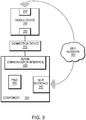
- Fig. 3 is a block diagram of an example mobile device 200 coupled via an example connection device 310 to an example component 320 (e.g., a controller, a user interface, or an endpoint) of a home automation system.
- the component includes a wired serial communication interface 330, a Wi-Fi Interface 340, as well as a Programmable System-on-Chip (PSoC) 350 that may support a programming environment.
- the connection device 310 couples the wired serial communication interface (e.g., 30-pin dock interface, Lightning interface, or USB interface, etc.) 250 of the mobile device 200 to the wired serial communication interface (e.g., a RS232 interface or other type of interface) 330 of the component 320.
- the connection device 310 may include hardware to support such a connection.
- connection device 310 may include a processor, an authentication chip, as well as other hardware (not shown).
- the connection device 310 may include a USB translation device as well as other hardware (not shown).
- the mobile device 200 may detect when it is connected to a component via the the connection device 320, and control commands may be passed from the mobile device 200 over the connection device 320 to configure a Wi-Fi interface 340 of the component so that the component may join the Wi-Fi network 370.
- control commands are sent over the connection device 320 to configure settings such as a network name (e.g., a service set identifier (SSID), a security type (e.g., Wired Equivalent Privacy (WEP), Wi-Fi Protected Access (WPA), etc.) a password (e.g., a SSID password), addresses (e.g., an Internet Protocol (IP) address of the component, a subnet mask, an IP address of a router, etc.) used to join the Wi-Fi network.
- SSID service set identifier
- WEP Wired Equivalent Privacy
- WPA Wi-Fi Protected Access
- addresses e.g., an Internet Protocol (IP) address of the component, a subnet mask, an IP address of a router, etc.
- IP Internet Protocol
- control commands are sent to at least configure the component's role or bindings and possibly controller settings, firmware, etc.
- a universal asynchronous receiver/transmitter (UART) protocol and related application program interface (API) supports the exchange of these control commands.
- the mobile device 200 may operate as a controller node, the connection device 310 may operate as a transparent middle node, and the component 330 may operate as a subordinate node.
- the mobile device 200 initially sends a common state packet over the connection device 310.
- the common state packet includes a UART pass-through command that instructs the connection device 310 to bridge communications.
- the connection device 310 determines a bus type of the interface the packet was received on, and detects the UART pass-through command.
- the connection device determines that the packet should be re-framed and sent out from a UART of the connection device 310 to the component 330.
- the packet is then received by the component 330.
- An acknowledgement packet may be sent back from the component 330 to the mobile device 200.
- the acknowledgment packet may include an uplink flag to indicate the direction of travel.
- the connection device 310 sees a packet with the uplink flag set, it may include a UART pass-through command in the packet, and then forward it onward to the mobile device 200.
- the UART pass-through command is used to distinguish between information originating at the connection device 200 and at the component 330.
- a communication channel is established between the mobile device 200 and component 330, usable when communication is not yet possible via the Wi-Fi network 370.
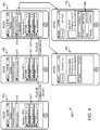
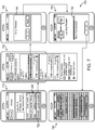
- Fig. 4 is a series of views 400 of an example mobile device 200, showing an example user interface on the touch sensitive display screen 240 while a connection device 310 and component 320 are being coupled to the mobile device.
- the connection device is still disconnected from the mobile device, and a status of "not connected" is indicated in a connected accessory display area 415.
- Other components accessible on the Wi-Fi network are indicated in Wi-Fi display area 417.
- the mobile device 200 detects when the connection device 310 is connected to it, and updates the view.
- the connection device 310 is now connected to the wired serial communication interface 250 of the mobile device, but not to the component 320.
- the connection device 310 is indicated in the connected accessory display area 415.
- the mobile device 200 detects when a component is connected to the connection device 310 and updates the view.
- the component 320 is now connected to the connection device 310.
- the component 310 here a controller having the model number "SSL-P018", is indicated in the connected accessory display area 415.
- the user has selected the connection device in the connected accessory display area 415, and additional information about the connection device 310 is shown.
- the user has selected the component in the connected accessory display area 415, and a main menu 460 for the component is shown. Using the main menu 460, the user may configure the component 320 to join the Wi-Fi network as well as configure additional settings of the component. When the component 320 has joined the Wi-Fi network, it may be shown in the Wi-Fi display area 417 of the views 410-430, for subsequent access.
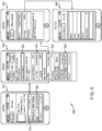
- Fig. 5 is a series of views 500 of an example mobile device 200, showing an example user interface while a user configures a component 320 to join a Wi-Fi network.
- a user may select an option 520 to configure the Wi-Fi settings of the component 320, and view 530 is then shown.
- view 530 the user interface shows a current Wi-Fi network that the mobile device 200 is connected to in area 532, and recently joined Wi-Fi networks in area 534.
- a network name, security, password, addresses and other information are already known by the mobile device 200. Still other accessible networks may be shown in area 536.
- a user may need to enter a network name, security, password, addresses and/or other information if one of these networks is desired, as shown in views 540 and 550. Addresses may also be entered using area 538 in view 530.
- the mobile device 200 sends control commands via the connection device 310 to the component 320 to configure the network name, security type, password, addresses, etc. to cause the component to join the Wi-Fi network. Once the component 320 has joined the Wi-Fi network, further control commands may be sent to the component 320 via the connection device 310 or via the now-accessible Wi-Fi network.
- Fig. 6 is a series of views 600 of an example mobile device 200, showing an example user interface while a user configures a role of a component 320 in the home automation system. From the main menu 460 shown in view 610, a user may select an option 620 to configure a role of the component 320, and an updated view 630 is shown. In view 630, various available roles for the component 320 are displayed in an area 640, and the user selects a desired role. In response to the user input, the mobile device 200 sends control commands to the component 320 to configure the role.
- Fig. 7 is a series of views 700 of an example mobile device 200, showing an example user interface while a user updates firmware of a component 320.
- a user may select an option 720 to configure firmware, and an updated view 730 is shown.
- view 730 various available firmwares, and versions thereof are shown.
- Firmware may be locally stored on the mobile device 200, or available in an online repository accessible by the mobile device 200.
- the user interface displays a confirmation prompt 740, as shown in view 750.
- the firmware is transferred from the mobile device 200 to the component 320.
- a status display 760 is presented as the firmware is transferred, as shown in view 770.
- a user may be able to cancel the transfer prior to its completion, as shown in view 780
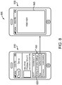
- Fig. 8 is a series of views 800 of an example mobile device 200, showing an example user interface while a user configures bindings and controller settings. From the main menu 460 shown in view 810, a user may select an option 820 to configure the bindings and controller settings. Upon selection, a web interface 840 displays controls for manipulating the bindings and controller settings, as shown in view 820. The web interface may be provided from the component 320 or another source, and the mobile device 200 may simply load and display webpages provided, without understanding their content.
- Fig. 9 is a flow chart of an example sequence of steps 900 to configure a component of a home automation system that is initially is inaccessible on a Wi-Fi network.
- the sequence of steps 900 may summarize aspects of the above discussed operation.
- a configuration app is executed on a mobile device.
- a user interface of the configuration app is displayed on a touch-sensitive display screen.
- a connection device is used to couple the mobile device to the component which is initially inaccessible on the Wi-Fi network.
- the connection device couples a wired serial communication interface of the mobile device to a wired serial communication of the component.
- the mobile device in response to input entered in the user interface being displayed on the touch-sensitive display screen, the mobile device sends control signals to the component via the connection device to configure Wi-Fi settings of the component, to cause the component join the Wi-Fi network.
- the mobile device in response to further input entered in the user interface being displayed on the touch-sensitive display screen, the mobile device sends additional control signals to the component via the connection device or the Wi-Fi network to configure additional settings of the now Wi-Fi accessible component.
- a software implementation may include computer-executable instructions stored in a non-transitory computer-readable medium, such as a volatile or persistent memory, a hard-disk, a compact disk (CD), or other tangible medium.
- a hardware implementation may include configured processors, logic circuits, application specific integrated circuits, and/or other types of hardware components.
- a combined software/hardware implementation may include both computer-executable instructions stored in a non-transitory computer-readable medium, as well as one or more hardware components, for example, processors, memories, etc. Accordingly, it should be understood that the above descriptions are meant to be taken only by way of example.
Description
- The present disclosure relates generally to home automation systems and more specifically to a connection device for configuring components of a home automation system that are initially inaccessible on a Wi-Fi network.
- Home automation systems are becoming increasingly popular in both residential and commercial buildings. In a typical home automation system, one or more controllers organize the system. The controllers operates under directions from a user, received on user interface devices in communication with the controllers. The controllers may control endpoints that implement functions to change the environment, and in some cases collect environmental data. Depending on the type of home automation system, the nature of the controllers, user interface devices, and endpoints may vary. Further, the same device may sometimes operate as both a controller, a user interface device, and/or an endpoint, depending on its capabilities and current role. As used herein, the term "component" should be understood to refer generally to controllers, user interface devices, and/or endpoints of a home automation system.
- A home automation system may include components related to any of a variety of different types of functions in the areas of lighting, climate control, audio/video, window shades and drapes, security and surveillance, communications, entry control, power management, and the like. For example, if the home automation system supports lighting control, controllers may include a lighting controller, user interface devices may include one or more remote controls and keypads, and endpoints may include load modules. Likewise, if the home automation system supports climate control, the controllers may include one or more heating ventilation and air conditioning (HVAC) controllers (or HVAC control functionality integrated into general purpose controllers), the user interface devices may include one or more remote controls, and the endpoints may include one or more thermostats, sensors, and the like.
- Some components may support wireless networking, and join and communicate over wireless local area networks (WLANs), or more specifically Wi-Fi networks. As used herein the term "Wi-Fi network" refers to a WLAN that is based on one or more of the Institute of Electrical and Electronics Engineers (IEEE) 802.11 standards. A Wi-Fi network may be used to pass control commands among the components to support ongoing home automation functions. The patent application document
WO2013/067569A1 discloses a power control device for controlling an electrical apparatus through a wireless communications link such as a Wi-Fi Direct peer-to-peer communications link, with a personal controller (e.g. smartphone), to control a supply of electricity to the electrical apparatus in domestic and commercial applications. While wireless networking circuitry may be readily integrated into components, configuring such components to join a Wi-Fi network and properly interact with one another may present challenges. Before a component has joined a Wi-Fi network, it may be inaccessible to other components via Wi-Fi communication. - In order to join a Wi-Fi network, a component typically must be configured with Wi-Fi settings, for example, a network name (e.g., service set identifier (SSID)), a security type (e.g., Wired Equivalent Privacy (WEP), Wi-Fi Protected Access (WPA) a password, addresses (e.g., an Internet Protocol (IP) address, a subnet mask, an IP address of a gateway/router), etc. Also, the component may need to have its role defined, have its firmware updated, and/or be configured with bindings and controller setting, before it can properly interact with other components. Patent application
US2009/003240A1 discloses a method for using a controlling device e.g. a remote control for configuring an appliance for use in a WiFi network. Information required to perform communication on the wireless local area network is obtained from a user through a setup wizard. - However, some components of home automation systems may lack robust user interfaces themselves that allow a user to easily configure these settings. A component, for example, a lighting controller, a keypad, etc., may lack any sort of display screen that could show such a user interface. Users may be required to undertake cumbersome and inefficient means to configure components.
- Accordingly, there is a need for improved techniques for configuring components of home automation systems, including Wi-Fi enabled components that may initially be inaccessible on a Wi-Fi network.
- The present invention provides a solution to the above mentioned aspects according to the independent claims. Preferred embodiments are provided by the dependent claims. The embodiments and/or examples of the following description which are not covered by the claims, are provided for illustrative purpose only and are only intended to assist the reader in understanding the present invention. However, such embodiments and/or examples which are not covered by the claims do not form part of the present invention that is solely defined by the claims.
- In one embodiment, a connection device is provided that couples a mobile device having a touch-sensitive display screen to a component (e.g., a controller, a user interface, or an endpoint) of a home automation system. The connection device couples a wired serial communication interface of the mobile device (e.g., a 30-pin dock interface, Lightning interface, Universal Serial Bus (USB) interface, etc.) to a wired serial communication interface (e.g., an RS232 interface or other type of interface) of the component of the home automation system. An authentication chip, processor, or other circuitry may be included internal to the connection device, and facilitate communication between the wired serial communication interfaces. The mobile device executes a configuration application (app), whose user interface is displayed on the touch-sensitive display screen. Using the user interface, a user may configure the component to join a Wi-Fi network, as well as configure more advanced settings of the component. For example, in response to input on the user interface, the configuration app on the mobile device may send control commands via the connection device to the component, to set a network name, a security type, a password, addresses, etc., to cause the component to join aWi-Fi network. Similarly, in response to further input on the user interface, the configuration app on the mobile device may send additional control commands via the connection device, or the Wi-Fi network, to the component to configure additional settings (e.g., a role, firmware, bindings and controller settings, etc.) of the component. In this manner, a user may use the mobile device to configure a component of a home automaton system that may lack any sort of display screen itself capable of providing a robust user interface.
- It should be understood that a variety of additional features and alternative embodiments may be implemented. This Summary is intended simply as an introduction to the reader, and does not indicate or imply that the examples mentioned herein cover all aspects of the invention, or are necessary or essential aspects of the invention.
- The description below refers to the accompanying drawings, of which:
-
Fig. 1 is a block diagram of an architecture of a home automation system that focuses on lighting control; -
Fig. 2 is a block diagram of an example mobile device; -
Fig. 3 is a block diagram of an example mobile device coupled via an example connection device to an example component; -
Fig. 4 is a series of views of an example mobile device, showing an example user interface on the touch sensitive display screen while the connection device and component are being coupled to the mobile device; -
Fig. 5 is a series of views of an example mobile device showing an example user interface while a user configures a component to join a Wi-Fi network; -
Fig. 6 is a series of views of an example mobile device, showing an example user interface while a user configures a role of a component in the home automation system; -
Fig. 7 is a series of views of an example mobile device, showing an example user interface while a user updates firmware of a component; -
Fig. 8 is a series of views of an example mobile device, showing an example user interface while a user configures bindings and controller settings; and -
Fig. 9 is a flow chart of an example sequence of steps to configure a component of a home automation system that is initially is inaccessible on a Wi-Fi network. -
Fig. 1 is a block diagram of an architecture of an examplehome automation system 100 that focuses on lighting control. The focus on lighting control is merely illustrative, and it should be understood that a home automation system may support a variety of different types of functions relating to lighting, climate control, audio/video, window shades and drapes, security and surveillance, communications, entry control, power management, and the like, and that the descriptions below are not limited to lighting control. A home automation system may be devoted to one of these functions, or a combination of multiple ones of these functions. A home automation system may be deployed in a residential home and the functions adapted to a residential environment. Alternatively, a home automation system may be deployed in a commercial building (such as an office building, store, factory, etc.) and these functions adapted to commercial requirements. - The example
home automation system 100 is composed of a number of home automation components (e.g., controllers, a user interfaces, and endpoints) related to lighting control. The controllers include alighting controller 110 and ahost controller 120. The user interfaces includekeypads 170,remote controls 175, and potentiallymobile devices 200. The endpoint units include load modules, lamp modules (not shown), and the like. - The
lighting controller 110 provides control and communication functionality, and supports, via amodule bus 130, theload modules 140. The load modules include dimmer modules and relay modules that dim and/or switch individual lighting devices, when directed to do so by thelighting controller 110. Further, thelighting controller 110 supports, via amodule bus 130,keypad link units 150 that are coupled, via arespective station bus 160, to keypads 170. Thekeypads 170 receive user input indicating lighting devices to dim and/or switch, which is provided back to thelighting controller 110. - The
lighting controller 110 is coupled, via a wired local area network (LAN) 180 to thehost controller 120. Thehost controller 120 is configured to control and monitor operations of thelighting controller 110, as well as to provide user interface interpretation and high-level control functions. One or morewireless access points 190 are coupled to theLAN 180, and support a WLAN, or more specifically, a Wi-Fi network. The Wi-Fi network is utilized byremote controls 175, andmobile devices 200. In addition to theremote controls 175 andmobile devices 200, one or more other components of thehome automation system 100 may utilize the Wi-Fi network. For example, thelighting controller 110,keypads 170 and other components may be Wi-Fi enabled, and use the Wi-Fi network to supplement, or (alternatively) in place of, wired connections. - In addition to receiving user input to control ongoing operation of a
home automation system 100,mobile devices 200 may be used to configure components of thehome automation system 100. Each individualmobile device 200 may be used in one or both of these roles. As used herein, the term "mobile device" refers to an electronic device that is adapted to be transported on one's person and includes a wireless communication interface and a touch sensitive display screen. Devices such as tablet computers (e.g., the iPad® tablet available from Apple, Inc.), smartphones (e.g., the iPhone® smartphones available from Apple, Inc., and Android® smartphones available from various suppliers), and certain portable media players (e.g., such as the iPod® touch available from Apple, Inc.), are considered mobile devices. A desktop computer would not be considered a mobile device. When used in a control role, amobile device 200 may execute a control application (app) and communicate with thehost controller 120. When used in a configuration role, amobile device 200 may execute a configuration app and communicate directly with individual non-controller components. -
Fig. 2 is a block diagram of an examplemobile device 200. Themobile device 200 includes aprocessor 210, amemory 220, awireless network interface 230, a touch-sensitive screen 240, a wiredserial communication interface 250, as well as other hardware. Theprocessor 210 includes logic configured to execute software and manipulate data from data structures. Thememory 220 includes a plurality of storage locations for storing the software and the data structures. Thewireless network interface 230 facilitates communication over a WLAN, or more specifically a Wi-Fi network. The touch-sensitive display screen 240 may receive user input in the form of gestures (e.g., touches, swipes, multi-touch gestures, etc.) from a user. Theserial communication interface 250 may be a 30-pin dock interface, a Lightning interface, a USB interface, or another type of interface. - An
operating system 260, portions of which are resident inmemory 220, functionally organizes themobile device 200. Theoperating system 260 may be an IOS® operating system available from Apple, Inc., an Android® operating system available from Google, Inc, or another type of operating system. A configuration app 270 is executed in conjunction with theoperating system 260, to permit themobile device 200 to operate in a configuration role, to configure a component (e.g., a controller, a user interface, or an endpoint) of thehome automation system 100. The configuration app 270 may display a user interface on the touch sensitive screen 270, and receive user input thereon. In addition, a control app (not shown) may also be stored in thememory 220 to permit themobile device 200 to operate in a control role and control ongoing operation of thehome automation system 100. The control app (not shown) may also display its user interface on the touch sensitive screen 270, and receive user input thereon. - As discussed above, sometimes a Wi-Fi enabled component of a
home automation system 100 may not yet be configured with Wi-Fi settings needed to join the network. Further, the component may lack a display screen capable of providing a robust user interface for configuring these Wi-Fi settings, and other settings of the component. By coupling theserial communication interface 250 of themobile device 200 to a serial communication interface of the component, via a special connection device, and using the configuration app 270 on themobile device 200, a user may configure the Wi-Fi and other settings. -
Fig. 3 is a block diagram of an examplemobile device 200 coupled via anexample connection device 310 to an example component 320 (e.g., a controller, a user interface, or an endpoint) of a home automation system. The component includes a wiredserial communication interface 330, a Wi-Fi Interface 340, as well as a Programmable System-on-Chip (PSoC) 350 that may support a programming environment. Theconnection device 310 couples the wired serial communication interface (e.g., 30-pin dock interface, Lightning interface, or USB interface, etc.) 250 of themobile device 200 to the wired serial communication interface (e.g., a RS232 interface or other type of interface) 330 of thecomponent 320. Theconnection device 310 may include hardware to support such a connection. For example, if theinterface 250 is a Lightning interface and theinterface 330 is an RS232 interface, theconnection device 310 may include a processor, an authentication chip, as well as other hardware (not shown). Alternatively, if theinterface 250 is a USB interface and theinterface 330 is an RS232 interface, theconnection device 310 may include a USB translation device as well as other hardware (not shown). - The
mobile device 200 may detect when it is connected to a component via the theconnection device 320, and control commands may be passed from themobile device 200 over theconnection device 320 to configure a Wi-Fi interface 340 of the component so that the component may join the Wi-Fi network 370. In response to input on the user interface of the configuration app 270, control commands are sent over theconnection device 320 to configure settings such as a network name (e.g., a service set identifier (SSID), a security type (e.g., Wired Equivalent Privacy (WEP), Wi-Fi Protected Access (WPA), etc.) a password (e.g., a SSID password), addresses (e.g., an Internet Protocol (IP) address of the component, a subnet mask, an IP address of a router, etc.) used to join the Wi-Fi network. Further, control commands are passed from themobile device 200 over theconnection device 320 to configure other hardware andsoftware 350 of thecomponent 320. In response to input on the user interface of the configuration app 270, control commands are sent to at least configure the component's role or bindings and possibly controller settings, firmware, etc. - A universal asynchronous receiver/transmitter (UART) protocol and related application program interface (API) supports the exchange of these control commands. Under the protocol, the
mobile device 200 may operate as a controller node, theconnection device 310 may operate as a transparent middle node, and thecomponent 330 may operate as a subordinate node. To establish communication, themobile device 200 initially sends a common state packet over theconnection device 310. The common state packet includes a UART pass-through command that
instructs theconnection device 310 to bridge communications. When theconnection device 310 receives the common state packet, it determines a bus type of the interface the packet was received on, and detects the UART pass-through command. Based on the bus type and UART pass-through command, the connection device determines that the packet should be re-framed and sent out from a UART of theconnection device 310 to thecomponent 330. The packet is then received by thecomponent 330. An acknowledgement packet may be sent back from thecomponent 330 to themobile device 200. The acknowledgment packet may include an uplink flag to indicate the direction of travel. When theconnection device 310 sees a packet with the uplink flag set, it may include a UART pass-through command in the packet, and then forward it onward to themobile device 200. Upon receipt at the mobile device, the UART pass-through command is used to distinguish between information originating at theconnection device 200 and at thecomponent 330. Through exchange of packets back and forth over theconnection device 310, a communication channel is established between themobile device 200 andcomponent 330, usable when communication is not yet possible via the Wi-Fi network 370. -
Fig. 4 is a series ofviews 400 of an examplemobile device 200, showing an example user interface on the touchsensitive display screen 240 while aconnection device 310 andcomponent 320 are being coupled to the mobile device. Inview 410, the connection device is still disconnected from the mobile device, and a status of "not connected" is indicated in a connectedaccessory display area 415. Other components accessible on the Wi-Fi network are indicated in Wi-Fi display area 417. Themobile device 200 detects when theconnection device 310 is connected to it, and updates the view. Inview 420, theconnection device 310 is now connected to the
wiredserial communication interface 250 of the mobile device, but not to thecomponent 320. Theconnection device 310 is indicated in the connectedaccessory display area 415. Themobile device 200 detects when a component is connected to theconnection device 310 and updates the view. Inview 430, thecomponent 320 is now connected to theconnection device 310. Thecomponent 310, here a controller having the model number "SSL-P018", is indicated in the connectedaccessory display area 415. Inview 440, the user has selected the connection device in the connectedaccessory display area 415, and additional information about the
connection device 310 is shown. Inview 450, the user has selected the component in the connectedaccessory display area 415, and amain menu 460 for the component is shown. Using themain menu 460, the user may configure thecomponent 320 to join the Wi-Fi network as well as configure additional settings of the component. When thecomponent 320 has joined the Wi-Fi network, it may be shown in the Wi-Fi display area 417 of the views 410-430, for subsequent access. -
Fig. 5 is a series ofviews 500 of an examplemobile device 200, showing an example user interface while a user configures acomponent 320 to join a Wi-Fi network. From themain menu 460 inview 510, a user may select anoption 520 to configure the Wi-Fi settings of thecomponent 320, andview 530 is then shown. Inview 530, the user interface shows a current Wi-Fi network that themobile device 200 is connected to inarea 532, and recently joined Wi-Fi networks inarea 534. For these Wi-Fi networks, a network name, security, password, addresses and other information are already known by themobile device 200. Still other accessible networks may be shown inarea 536. A user may need to enter a network name, security, password, addresses and/or other information if one of these networks is desired, as shown inviews area 538 inview 530. In response to the user input entered inviews area 538, themobile device 200 sends control commands via theconnection device 310 to thecomponent 320 to configure the network name, security type, password, addresses, etc. to cause the component to join the Wi-Fi network. Once thecomponent 320 has joined the Wi-Fi network, further control commands may be sent to thecomponent 320 via theconnection device 310 or via the now-accessible Wi-Fi network. -
Fig. 6 is a series ofviews 600 of an examplemobile device 200, showing an example user interface while a user configures a role of acomponent 320 in the home automation system. From themain menu 460 shown inview 610, a user may select anoption 620 to configure a role of thecomponent 320, and an updatedview 630 is shown. Inview 630, various available roles for thecomponent 320 are displayed in anarea 640, and the user selects a desired role. In response to the user input, themobile device 200 sends control commands to thecomponent 320 to configure the role. -
Fig. 7 is a series ofviews 700 of an examplemobile device 200, showing an example user interface while a user updates firmware of acomponent 320. From themain menu 460 shown inview 710, a user may select anoption 720 to configure firmware, and an updatedview 730 is shown. Inview 730, various available firmwares, and versions thereof are shown. Firmware may be locally stored on themobile device 200, or available in an online repository accessible by themobile device 200. Upon selection of a firmware and version by the user, the user interface displays aconfirmation prompt 740, as shown inview 750. In response to user confirmation, the firmware is transferred from themobile device 200 to thecomponent 320. Astatus display 760 is presented as the firmware is transferred, as shown inview 770. A user may be able to cancel the transfer prior to its completion, as shown inview 780 -
Fig. 8 is a series ofviews 800 of an examplemobile device 200, showing an example user interface while a user configures bindings and controller settings. From themain menu 460 shown inview 810, a user may select anoption 820 to configure the bindings and controller settings. Upon selection, aweb interface 840 displays controls for manipulating the bindings and controller settings, as shown inview 820. The web interface may be provided from thecomponent 320 or another source, and themobile device 200 may simply load and display webpages provided, without understanding their content. -
Fig. 9 is a flow chart of an example sequence ofsteps 900 to configure a component of a home automation system that is initially is inaccessible on a Wi-Fi network. The sequence ofsteps 900 may summarize aspects of the above discussed operation. Atstep 910, a configuration app is executed on a mobile device. A user interface of the configuration app is displayed on a touch-sensitive display screen. Atstep 920, a connection device is used to couple the mobile device to the component which is initially inaccessible on the Wi-Fi network. The connection device couples a wired serial communication interface of the mobile device to a wired serial communication of the component. Atstep 930, in response to input entered in the user interface being displayed on the touch-sensitive display screen, the mobile device sends control signals to the component via the connection device to configure Wi-Fi settings of the component, to cause the component join the Wi-Fi network. At step 940, in response to further input entered in the user interface being displayed on the touch-sensitive display screen, the mobile device sends additional control signals to the component via the connection device or the Wi-Fi network to configure additional settings of the now Wi-Fi accessible component. - It should be understood that various adaptations and modifications may be made within the scope of the embodiments discussed herein. Further, it should be understood that at least some portions of the above-described techniques may be implemented in software, in hardware, or a combination thereof. A software implementation may include computer-executable instructions stored in a non-transitory computer-readable medium, such as a volatile or persistent memory, a hard-disk, a compact disk (CD), or other tangible medium. A hardware implementation may include configured processors, logic circuits, application specific integrated circuits, and/or other types of hardware components. Further, a combined software/hardware implementation may include both computer-executable instructions stored in a non-transitory computer-readable medium, as well as one or more hardware components, for example, processors, memories, etc. Accordingly, it should be understood that the above descriptions are meant to be taken only by way of example.
Claims (14)
- A method for configuring a component (320) of a home automation system that
initially is inaccessible on a Wi-Fi network, comprising:executing a configuration application, app, on a mobile device (200) having a touch-sensitive display screen, a user interface of the configuration app being displayed to a user on the touch-sensitive display screen;coupling the mobile device (200) to the component (320) of the home automation system via a connection device (310), the connection device connecting a wired serial communication interface of the mobile device (250) to a wired serial communication interface of the component (330) and capable of operating as a transparent middle node in response to a universal asynchronous receiver/transmitter, UART, pass-through command;in response to input entered in the user interface being displayed on the touch-sensitive display screen, sending control signals from the mobile device (200) to the component (320) via the connection device (310) to configure Wi-Fi settings of the component to cause the component to join the Wi-Fi network (370), the control signals to include the UART pass-through command to cause the connection device to forward the control signals to the component (320); in response to further input entered in the user interface being displayed on the touch-sensitive display screen, sending additional control signals from the mobile device (200) to the component (320) via the connection device (310) to at least one of assign the component a role within the home automation system or bind the component (320), the additional control signals to include the UART pass-through command to cause the connection device to forward the control signals to the component (320). - The method of claim 1, wherein the sending additional control signals sends additional control signals via the Wi-Fi network (370) to the component (320).
- The method of claim 1, wherein the mobile device (200) is a smartphone,
- The method of claim 1, wherein the wired serial communication interface of the mobile device (250) is a Lightning interface and the wired serial communication interface of the component (330) is an RS232 interface.
- The method of claim 1, wherein the wired serial communication interface of the mobile device (250) is a Universal Serial Bus, USB, interface and the wired serial communication interface of the component (330) is an RS232 interface,
- The method of claim 1, wherein the mobile device (200) operates as a controller node, the component (320) operates as a subordinate node, the control signals are packets sent from the controller node to the transparent middle node.
- The method of claim 1, wherein the home automation system controls lighting devices, and the component (320) is a lighting controller or a keypad,
- The method of claim 1, further comprising:executing a control app on the mobile device (200) or another mobile device, the control app configured to control ongoing operation of the home automation system after the Wi-Fi settings and additional settings of the component (320) have been configured.
- A system for configuring a component (320) of a home automation system that initially is inaccessible on a Wi-Fi network, comprising:a mobile device (200) having a processor, a memory, a wired serial communication interface (250) and a touch sensitive display screen, wherein the memory is configured to store a configuration application, app, the touch sensitive display screen is configured to show a user interface of the configuration app, and the processor is configured to execute the configuration app, and the configuration app, when executed, is configured to send control signals over the wired serial communication interface in response to input entered in the user interface, the control signals to configure Wi-Fi settings of the component of the home automation system to cause the component to join the Wi-Fi network (370), the control signals to include a universal asynchronous receiver/transmitter, UART, pass-through command; anda connection device (310) coupled to the wired serial communication interface of the mobile device (250) and a wired serial communication interface of the component (330), the connection device (310) configured to operate as a transparent middle node between the mobile device (200) and the component (320) in response to the UART pass-through command and propagate the control signals there between, wherein the configuration app, when executed, is further operable to send additional control signals to the component via the connection device (310) to at least one of assign the component a role within the home automation system or bind the component, the additional control signals to include the UART pass-through command.
- The system of claim 9, wherein the mobile device (200) is a smartphone,
- The system of claim 9, wherein the wired serial communication interface of the mobile device (250) is a Lightning interface and the wired serial communication interface of the component (330) is an RS232 interface.
- The system of claim 9, wherein the wired serial communication interface of the mobile device (250) is a universal serial bus, USB, interface and the wired serial communication interface of the component (330) is an RS232 interface,
- The system of claim 9, wherein the home automation system controls lighting devices, the component (320) is a lighting controller or a keypad,
- The system of claim 9, wherein the memory of the mobile device (200) or a memory
of another mobile device is configured to store a control app, the control app, when executed by the processor of the mobile device or a processor of the another mobile device, to control ongoing operation of the home automation system after the Wi-Fi settings and additional settings of the component (320) have
been configured.
Applications Claiming Priority (2)
| Application Number | Priority Date | Filing Date | Title |
|---|---|---|---|
| US13/923,826 US9736616B2 (en) | 2013-06-21 | 2013-06-21 | Configuration connection device |
| PCT/US2014/041474 WO2014204689A1 (en) | 2013-06-21 | 2014-06-09 | A configuration connection device |
Publications (2)
| Publication Number | Publication Date |
|---|---|
| EP3011704A1 EP3011704A1 (en) | 2016-04-27 |
| EP3011704B1 true EP3011704B1 (en) | 2021-04-14 |
Family
ID=51134373
Family Applications (1)
| Application Number | Title | Priority Date | Filing Date |
|---|---|---|---|
| EP14736177.8A Active EP3011704B1 (en) | 2013-06-21 | 2014-06-09 | A configuration connection device |
Country Status (10)
| Country | Link |
|---|---|
| US (1) | US9736616B2 (en) |
| EP (1) | EP3011704B1 (en) |
| JP (1) | JP6473743B2 (en) |
| KR (1) | KR102225408B1 (en) |
| CN (1) | CN105453486B (en) |
| AU (2) | AU2014281083A1 (en) |
| CA (1) | CA2916248C (en) |
| ES (1) | ES2872400T3 (en) |
| IL (1) | IL243256B (en) |
| WO (1) | WO2014204689A1 (en) |
Families Citing this family (12)
| Publication number | Priority date | Publication date | Assignee | Title |
|---|---|---|---|---|
| US9867260B2 (en) | 2013-06-26 | 2018-01-09 | Savant Systems, Llc | Lighting controller |
| US9998326B2 (en) * | 2014-02-13 | 2018-06-12 | General Electric Company | Systems and methods for touch-less commissioning of intelligent electronic devices |
| US9754090B2 (en) * | 2014-05-07 | 2017-09-05 | Vivint, Inc. | Setting up a system with a mobile device |
| US10032364B2 (en) * | 2014-05-15 | 2018-07-24 | Savant Systems, Llc | Standalone wireless lighting application |
| CN105446471A (en) * | 2014-09-02 | 2016-03-30 | 昆盈企业股份有限公司 | Peripheral input device and setting method thereof |
| US10205626B2 (en) * | 2014-12-29 | 2019-02-12 | International Business Machines Corporation | Systems and methods for online purchases of integrated services |
| CN104812131B (en) * | 2015-04-14 | 2018-12-18 | 周贤和 | A kind of intelligent electrical control system |
| US9806900B2 (en) * | 2015-10-05 | 2017-10-31 | Savant Systems, Llc | Wireless provisioning and configuring of hardware elements of a home automation system |
| US10594627B2 (en) | 2016-01-27 | 2020-03-17 | Oracle International Corporation | System and method for supporting scalable representation of switch port status in a high performance computing environment |
| CN107205239B (en) * | 2017-05-26 | 2020-06-16 | 广东美的厨房电器制造有限公司 | Method for detecting wireless network connection and detection equipment |
| US10292089B2 (en) | 2017-09-18 | 2019-05-14 | Sonos, Inc. | Re-establishing connectivity on lost players |
| CN109981747B (en) * | 2019-03-04 | 2022-06-03 | 深圳绿米联创科技有限公司 | Device control method, device, electronic device and storage medium |
Family Cites Families (24)
| Publication number | Priority date | Publication date | Assignee | Title |
|---|---|---|---|---|
| JP2002236561A (en) * | 2001-02-07 | 2002-08-23 | Nec Corp | Setting device for radio lan printer equipment |
| JP5054129B2 (en) * | 2003-06-20 | 2012-10-24 | キヤノン株式会社 | Information processing apparatus, control method therefor, and program |
| US7490350B1 (en) * | 2004-03-12 | 2009-02-10 | Sca Technica, Inc. | Achieving high assurance connectivity on computing devices and defeating blended hacking attacks |
| US7757010B2 (en) * | 2006-04-28 | 2010-07-13 | Mediatek Inc. | Systems and methods for managing mass storage devices in electronic devices |
| GB2438224A (en) * | 2006-05-17 | 2007-11-21 | Plamen Spassov Vassilev | Automatic Bathtub Filler and Circulation system |
| US20130150004A1 (en) * | 2006-08-11 | 2013-06-13 | Michael Rosen | Method and apparatus for reducing mobile phone usage while driving |
| US8254352B2 (en) * | 2007-06-28 | 2012-08-28 | Universal Electronics Inc. | System and method for configuration of network-capable appliances |
| TW200952536A (en) * | 2008-06-11 | 2009-12-16 | Asustek Comp Inc | Wireless device and method for automatically establishing wireless connection |
| EP3089558A3 (en) * | 2008-11-26 | 2017-01-18 | Wireless Environment, LLC | Wireless lighting devices and applications |
| KR101801682B1 (en) * | 2009-07-24 | 2017-11-27 | 필립스 라이팅 홀딩 비.브이. | A lighting system and a method for determining the energy consumption of lighting scenes of the lighting system |
| WO2012018526A1 (en) * | 2010-07-26 | 2012-02-09 | Lightwaves Systems, Inc. | Improved high bandwidth data transport system for use in a smartgrid |
| US8918219B2 (en) * | 2010-11-19 | 2014-12-23 | Google Inc. | User friendly interface for control unit |
| US8719581B2 (en) * | 2010-09-22 | 2014-05-06 | Savant Systems, Llc | Programmable multimedia controller with flexible user access and shared device configurations |
| US8583040B2 (en) * | 2010-10-01 | 2013-11-12 | Digi International Inc. | Devices, systems, and methods for configuring a wireless device |
| JP5177460B2 (en) * | 2010-12-10 | 2013-04-03 | ブラザー工業株式会社 | Information processing system |
| JP5565362B2 (en) * | 2011-03-30 | 2014-08-06 | ブラザー工業株式会社 | Control device |
| US20120306621A1 (en) * | 2011-06-03 | 2012-12-06 | Leviton Manufacturing Co., Inc. | Lighting control network configuration with rfid devices |
| WO2013012547A1 (en) * | 2011-06-30 | 2013-01-24 | Lutron Electronics Co., Inc. | Load control device having internet connectivity, and method of programming the same using a smart phone |
| WO2013003804A2 (en) * | 2011-06-30 | 2013-01-03 | Lutron Electronics Co., Inc. | Method for programming a load control device using a smart phone |
| US9386666B2 (en) | 2011-06-30 | 2016-07-05 | Lutron Electronics Co., Inc. | Method of optically transmitting digital information from a smart phone to a control device |
| JP2013055463A (en) * | 2011-09-02 | 2013-03-21 | Canon Inc | Wireless setting control device, control method therefor, and control program |
| KR20140099897A (en) | 2011-11-07 | 2014-08-13 | 코르테크 인더스트리스 피티와이 리미티드 | Adaptable wireless power, light and automation system |
| US9134493B2 (en) * | 2012-03-07 | 2015-09-15 | Celerity Technologies Inc. | Fiber optic cable with electrical connectors at both ends |
| US9488994B2 (en) * | 2012-03-29 | 2016-11-08 | Honeywell International Inc. | Method and system for configuring wireless sensors in an HVAC system |
-
2013
- 2013-06-21 US US13/923,826 patent/US9736616B2/en active Active
-
2014
- 2014-06-09 ES ES14736177T patent/ES2872400T3/en active Active
- 2014-06-09 WO PCT/US2014/041474 patent/WO2014204689A1/en active Application Filing
- 2014-06-09 EP EP14736177.8A patent/EP3011704B1/en active Active
- 2014-06-09 AU AU2014281083A patent/AU2014281083A1/en not_active Abandoned
- 2014-06-09 CA CA2916248A patent/CA2916248C/en active Active
- 2014-06-09 JP JP2016521437A patent/JP6473743B2/en active Active
- 2014-06-09 CN CN201480045939.8A patent/CN105453486B/en active Active
- 2014-06-09 KR KR1020167001843A patent/KR102225408B1/en active IP Right Grant
-
2015
- 2015-12-21 IL IL243256A patent/IL243256B/en active IP Right Grant
-
2018
- 2018-05-04 AU AU2018203123A patent/AU2018203123B2/en active Active
Non-Patent Citations (1)
| Title |
|---|
| None * |
Also Published As
| Publication number | Publication date |
|---|---|
| JP6473743B2 (en) | 2019-02-20 |
| CN105453486A (en) | 2016-03-30 |
| EP3011704A1 (en) | 2016-04-27 |
| WO2014204689A1 (en) | 2014-12-24 |
| JP2016524422A (en) | 2016-08-12 |
| CA2916248C (en) | 2023-01-17 |
| KR102225408B1 (en) | 2021-03-08 |
| US9736616B2 (en) | 2017-08-15 |
| CN105453486B (en) | 2019-06-07 |
| AU2018203123B2 (en) | 2019-03-14 |
| KR20160024386A (en) | 2016-03-04 |
| AU2014281083A1 (en) | 2016-01-21 |
| US20140376528A1 (en) | 2014-12-25 |
| IL243256B (en) | 2019-12-31 |
| AU2018203123A1 (en) | 2018-05-24 |
| ES2872400T3 (en) | 2021-11-02 |
| CA2916248A1 (en) | 2014-12-24 |
| IL243256A0 (en) | 2016-02-29 |
Similar Documents
| Publication | Publication Date | Title |
|---|---|---|
| AU2018203123B2 (en) | A configuration connection device | |
| US10931470B1 (en) | Thermostat synchronization via remote input device | |
| KR102350430B1 (en) | Over-the-air provisioning and configuration of hardware elements in a home automation system | |
| EP3014593B1 (en) | Lighting controller | |
| TWI488463B (en) | Gateway, smart home system and smart control method of home appliance thereof | |
| US20150280935A1 (en) | Thermostat code input system and method therefor | |
| CN112789828A (en) | Intelligent adaptation of remote control functions in a local area network | |
| CN108702315B (en) | Establishing a connection between two local devices connected to different networks | |
| KR101590746B1 (en) | Method and apparatus for setting net-work connection with electronic device | |
| JP6150516B2 (en) | Facility management system, portable terminal, facility management apparatus, and facility management method | |
| KR101333656B1 (en) | Building automation system using near field communication | |
| US20210204128A1 (en) | End user inclusion and access of devices | |
| KR20160126787A (en) | Near field communication hub and system for remote controlling using the same |
Legal Events
| Date | Code | Title | Description |
|---|---|---|---|
| PUAI | Public reference made under article 153(3) epc to a published international application that has entered the european phase |
Free format text: ORIGINAL CODE: 0009012 |
|
| 17P | Request for examination filed |
Effective date: 20151218 |
|
| AK | Designated contracting states |
Kind code of ref document: A1 Designated state(s): AL AT BE BG CH CY CZ DE DK EE ES FI FR GB GR HR HU IE IS IT LI LT LU LV MC MK MT NL NO PL PT RO RS SE SI SK SM TR |
|
| AX | Request for extension of the european patent |
Extension state: BA ME |
|
| DAX | Request for extension of the european patent (deleted) | ||
| STAA | Information on the status of an ep patent application or granted ep patent |
Free format text: STATUS: EXAMINATION IS IN PROGRESS |
|
| 17Q | First examination report despatched |
Effective date: 20180118 |
|
| RAP1 | Party data changed (applicant data changed or rights of an application transferred) |
Owner name: SAVANT SYSTEMS, INC. |
|
| REG | Reference to a national code |
Ref country code: DE Ref legal event code: R079 Ref document number: 602014076568 Country of ref document: DE Free format text: PREVIOUS MAIN CLASS: H04L0012280000 Ipc: H04L0012240000 |
|
| GRAP | Despatch of communication of intention to grant a patent |
Free format text: ORIGINAL CODE: EPIDOSNIGR1 |
|
| STAA | Information on the status of an ep patent application or granted ep patent |
Free format text: STATUS: GRANT OF PATENT IS INTENDED |
|
| RIC1 | Information provided on ipc code assigned before grant |
Ipc: H04W 4/50 20180101ALI20201130BHEP Ipc: H05B 47/19 20200101ALI20201130BHEP Ipc: H04L 12/24 20060101AFI20201130BHEP Ipc: H04L 12/28 20060101ALI20201130BHEP Ipc: H04W 84/12 20090101ALI20201130BHEP Ipc: H04W 12/00 20090101ALI20201130BHEP Ipc: H04W 12/04 20090101ALI20201130BHEP |
|
| INTG | Intention to grant announced |
Effective date: 20201215 |
|
| GRAS | Grant fee paid |
Free format text: ORIGINAL CODE: EPIDOSNIGR3 |
|
| GRAA | (expected) grant |
Free format text: ORIGINAL CODE: 0009210 |
|
| STAA | Information on the status of an ep patent application or granted ep patent |
Free format text: STATUS: THE PATENT HAS BEEN GRANTED |
|
| AK | Designated contracting states |
Kind code of ref document: B1 Designated state(s): AL AT BE BG CH CY CZ DE DK EE ES FI FR GB GR HR HU IE IS IT LI LT LU LV MC MK MT NL NO PL PT RO RS SE SI SK SM TR |
|
| REG | Reference to a national code |
Ref country code: GB Ref legal event code: FG4D |
|
| REG | Reference to a national code |
Ref country code: CH Ref legal event code: EP |
|
| REG | Reference to a national code |
Ref country code: DE Ref legal event code: R096 Ref document number: 602014076568 Country of ref document: DE |
|
| REG | Reference to a national code |
Ref country code: IE Ref legal event code: FG4D |
|
| REG | Reference to a national code |
Ref country code: AT Ref legal event code: REF Ref document number: 1383436 Country of ref document: AT Kind code of ref document: T Effective date: 20210515 |
|
| REG | Reference to a national code |
Ref country code: LT Ref legal event code: MG9D |
|
| REG | Reference to a national code |
Ref country code: AT Ref legal event code: MK05 Ref document number: 1383436 Country of ref document: AT Kind code of ref document: T Effective date: 20210414 |
|
| REG | Reference to a national code |
Ref country code: NL Ref legal event code: MP Effective date: 20210414 |
|
| PG25 | Lapsed in a contracting state [announced via postgrant information from national office to epo] |
Ref country code: AT Free format text: LAPSE BECAUSE OF FAILURE TO SUBMIT A TRANSLATION OF THE DESCRIPTION OR TO PAY THE FEE WITHIN THE PRESCRIBED TIME-LIMIT Effective date: 20210414 Ref country code: BG Free format text: LAPSE BECAUSE OF FAILURE TO SUBMIT A TRANSLATION OF THE DESCRIPTION OR TO PAY THE FEE WITHIN THE PRESCRIBED TIME-LIMIT Effective date: 20210714 Ref country code: NL Free format text: LAPSE BECAUSE OF FAILURE TO SUBMIT A TRANSLATION OF THE DESCRIPTION OR TO PAY THE FEE WITHIN THE PRESCRIBED TIME-LIMIT Effective date: 20210414 Ref country code: LT Free format text: LAPSE BECAUSE OF FAILURE TO SUBMIT A TRANSLATION OF THE DESCRIPTION OR TO PAY THE FEE WITHIN THE PRESCRIBED TIME-LIMIT Effective date: 20210414 Ref country code: FI Free format text: LAPSE BECAUSE OF FAILURE TO SUBMIT A TRANSLATION OF THE DESCRIPTION OR TO PAY THE FEE WITHIN THE PRESCRIBED TIME-LIMIT Effective date: 20210414 Ref country code: HR Free format text: LAPSE BECAUSE OF FAILURE TO SUBMIT A TRANSLATION OF THE DESCRIPTION OR TO PAY THE FEE WITHIN THE PRESCRIBED TIME-LIMIT Effective date: 20210414 |
|
| REG | Reference to a national code |
Ref country code: ES Ref legal event code: FG2A Ref document number: 2872400 Country of ref document: ES Kind code of ref document: T3 Effective date: 20211102 |
|
| REG | Reference to a national code |
Ref country code: DE Ref legal event code: R079 Ref document number: 602014076568 Country of ref document: DE Free format text: PREVIOUS MAIN CLASS: H04L0012240000 Ipc: H04L0041000000 |
|
| PG25 | Lapsed in a contracting state [announced via postgrant information from national office to epo] |
Ref country code: NO Free format text: LAPSE BECAUSE OF FAILURE TO SUBMIT A TRANSLATION OF THE DESCRIPTION OR TO PAY THE FEE WITHIN THE PRESCRIBED TIME-LIMIT Effective date: 20210714 Ref country code: PT Free format text: LAPSE BECAUSE OF FAILURE TO SUBMIT A TRANSLATION OF THE DESCRIPTION OR TO PAY THE FEE WITHIN THE PRESCRIBED TIME-LIMIT Effective date: 20210816 Ref country code: PL Free format text: LAPSE BECAUSE OF FAILURE TO SUBMIT A TRANSLATION OF THE DESCRIPTION OR TO PAY THE FEE WITHIN THE PRESCRIBED TIME-LIMIT Effective date: 20210414 Ref country code: SE Free format text: LAPSE BECAUSE OF FAILURE TO SUBMIT A TRANSLATION OF THE DESCRIPTION OR TO PAY THE FEE WITHIN THE PRESCRIBED TIME-LIMIT Effective date: 20210414 Ref country code: RS Free format text: LAPSE BECAUSE OF FAILURE TO SUBMIT A TRANSLATION OF THE DESCRIPTION OR TO PAY THE FEE WITHIN THE PRESCRIBED TIME-LIMIT Effective date: 20210414 Ref country code: LV Free format text: LAPSE BECAUSE OF FAILURE TO SUBMIT A TRANSLATION OF THE DESCRIPTION OR TO PAY THE FEE WITHIN THE PRESCRIBED TIME-LIMIT Effective date: 20210414 Ref country code: IS Free format text: LAPSE BECAUSE OF FAILURE TO SUBMIT A TRANSLATION OF THE DESCRIPTION OR TO PAY THE FEE WITHIN THE PRESCRIBED TIME-LIMIT Effective date: 20210814 Ref country code: GR Free format text: LAPSE BECAUSE OF FAILURE TO SUBMIT A TRANSLATION OF THE DESCRIPTION OR TO PAY THE FEE WITHIN THE PRESCRIBED TIME-LIMIT Effective date: 20210715 |
|
| REG | Reference to a national code |
Ref country code: DE Ref legal event code: R097 Ref document number: 602014076568 Country of ref document: DE |
|
| PG25 | Lapsed in a contracting state [announced via postgrant information from national office to epo] |
Ref country code: DK Free format text: LAPSE BECAUSE OF FAILURE TO SUBMIT A TRANSLATION OF THE DESCRIPTION OR TO PAY THE FEE WITHIN THE PRESCRIBED TIME-LIMIT Effective date: 20210414 Ref country code: EE Free format text: LAPSE BECAUSE OF FAILURE TO SUBMIT A TRANSLATION OF THE DESCRIPTION OR TO PAY THE FEE WITHIN THE PRESCRIBED TIME-LIMIT Effective date: 20210414 Ref country code: CZ Free format text: LAPSE BECAUSE OF FAILURE TO SUBMIT A TRANSLATION OF THE DESCRIPTION OR TO PAY THE FEE WITHIN THE PRESCRIBED TIME-LIMIT Effective date: 20210414 Ref country code: SK Free format text: LAPSE BECAUSE OF FAILURE TO SUBMIT A TRANSLATION OF THE DESCRIPTION OR TO PAY THE FEE WITHIN THE PRESCRIBED TIME-LIMIT Effective date: 20210414 Ref country code: SM Free format text: LAPSE BECAUSE OF FAILURE TO SUBMIT A TRANSLATION OF THE DESCRIPTION OR TO PAY THE FEE WITHIN THE PRESCRIBED TIME-LIMIT Effective date: 20210414 Ref country code: RO Free format text: LAPSE BECAUSE OF FAILURE TO SUBMIT A TRANSLATION OF THE DESCRIPTION OR TO PAY THE FEE WITHIN THE PRESCRIBED TIME-LIMIT Effective date: 20210414 Ref country code: MC Free format text: LAPSE BECAUSE OF FAILURE TO SUBMIT A TRANSLATION OF THE DESCRIPTION OR TO PAY THE FEE WITHIN THE PRESCRIBED TIME-LIMIT Effective date: 20210414 |
|
| REG | Reference to a national code |
Ref country code: CH Ref legal event code: PL |
|
| PLBE | No opposition filed within time limit |
Free format text: ORIGINAL CODE: 0009261 |
|
| STAA | Information on the status of an ep patent application or granted ep patent |
Free format text: STATUS: NO OPPOSITION FILED WITHIN TIME LIMIT |
|
| REG | Reference to a national code |
Ref country code: BE Ref legal event code: MM Effective date: 20210630 |
|
| 26N | No opposition filed |
Effective date: 20220117 |
|
| PG25 | Lapsed in a contracting state [announced via postgrant information from national office to epo] |
Ref country code: LU Free format text: LAPSE BECAUSE OF NON-PAYMENT OF DUE FEES Effective date: 20210609 |
|
| PG25 | Lapsed in a contracting state [announced via postgrant information from national office to epo] |
Ref country code: LI Free format text: LAPSE BECAUSE OF NON-PAYMENT OF DUE FEES Effective date: 20210630 Ref country code: IE Free format text: LAPSE BECAUSE OF NON-PAYMENT OF DUE FEES Effective date: 20210609 Ref country code: CH Free format text: LAPSE BECAUSE OF NON-PAYMENT OF DUE FEES Effective date: 20210630 |
|
| PG25 | Lapsed in a contracting state [announced via postgrant information from national office to epo] |
Ref country code: IS Free format text: LAPSE BECAUSE OF FAILURE TO SUBMIT A TRANSLATION OF THE DESCRIPTION OR TO PAY THE FEE WITHIN THE PRESCRIBED TIME-LIMIT Effective date: 20210814 Ref country code: AL Free format text: LAPSE BECAUSE OF FAILURE TO SUBMIT A TRANSLATION OF THE DESCRIPTION OR TO PAY THE FEE WITHIN THE PRESCRIBED TIME-LIMIT Effective date: 20210414 |
|
| PG25 | Lapsed in a contracting state [announced via postgrant information from national office to epo] |
Ref country code: BE Free format text: LAPSE BECAUSE OF NON-PAYMENT OF DUE FEES Effective date: 20210630 |
|
| PG25 | Lapsed in a contracting state [announced via postgrant information from national office to epo] |
Ref country code: HU Free format text: LAPSE BECAUSE OF FAILURE TO SUBMIT A TRANSLATION OF THE DESCRIPTION OR TO PAY THE FEE WITHIN THE PRESCRIBED TIME-LIMIT; INVALID AB INITIO Effective date: 20140609 |
|
| PG25 | Lapsed in a contracting state [announced via postgrant information from national office to epo] |
Ref country code: CY Free format text: LAPSE BECAUSE OF FAILURE TO SUBMIT A TRANSLATION OF THE DESCRIPTION OR TO PAY THE FEE WITHIN THE PRESCRIBED TIME-LIMIT Effective date: 20210414 |
|
| P01 | Opt-out of the competence of the unified patent court (upc) registered |
Effective date: 20230531 |
|
| PGFP | Annual fee paid to national office [announced via postgrant information from national office to epo] |
Ref country code: FR Payment date: 20230626 Year of fee payment: 10 Ref country code: DE Payment date: 20230626 Year of fee payment: 10 |
|
| PGFP | Annual fee paid to national office [announced via postgrant information from national office to epo] |
Ref country code: IT Payment date: 20230620 Year of fee payment: 10 Ref country code: GB Payment date: 20230627 Year of fee payment: 10 Ref country code: ES Payment date: 20230703 Year of fee payment: 10 |