EP3011153B2 - Storage tank with a heating device - Google Patents
Storage tank with a heating device Download PDFInfo
- Publication number
- EP3011153B2 EP3011153B2 EP14721828.3A EP14721828A EP3011153B2 EP 3011153 B2 EP3011153 B2 EP 3011153B2 EP 14721828 A EP14721828 A EP 14721828A EP 3011153 B2 EP3011153 B2 EP 3011153B2
- Authority
- EP
- European Patent Office
- Prior art keywords
- volume
- fluid
- heating element
- tank
- supply tank
- Prior art date
- Legal status (The legal status is an assumption and is not a legal conclusion. Google has not performed a legal analysis and makes no representation as to the accuracy of the status listed.)
- Active
Links
Images

Classifications
-
- F—MECHANICAL ENGINEERING; LIGHTING; HEATING; WEAPONS; BLASTING
- F01—MACHINES OR ENGINES IN GENERAL; ENGINE PLANTS IN GENERAL; STEAM ENGINES
- F01N—GAS-FLOW SILENCERS OR EXHAUST APPARATUS FOR MACHINES OR ENGINES IN GENERAL; GAS-FLOW SILENCERS OR EXHAUST APPARATUS FOR INTERNAL COMBUSTION ENGINES
- F01N3/00—Exhaust or silencing apparatus having means for purifying, rendering innocuous, or otherwise treating exhaust
- F01N3/08—Exhaust or silencing apparatus having means for purifying, rendering innocuous, or otherwise treating exhaust for rendering innocuous
- F01N3/10—Exhaust or silencing apparatus having means for purifying, rendering innocuous, or otherwise treating exhaust for rendering innocuous by thermal or catalytic conversion of noxious components of exhaust
- F01N3/18—Exhaust or silencing apparatus having means for purifying, rendering innocuous, or otherwise treating exhaust for rendering innocuous by thermal or catalytic conversion of noxious components of exhaust characterised by methods of operation; Control
- F01N3/20—Exhaust or silencing apparatus having means for purifying, rendering innocuous, or otherwise treating exhaust for rendering innocuous by thermal or catalytic conversion of noxious components of exhaust characterised by methods of operation; Control specially adapted for catalytic conversion ; Methods of operation or control of catalytic converters
- F01N3/2066—Selective catalytic reduction [SCR]
-
- F—MECHANICAL ENGINEERING; LIGHTING; HEATING; WEAPONS; BLASTING
- F01—MACHINES OR ENGINES IN GENERAL; ENGINE PLANTS IN GENERAL; STEAM ENGINES
- F01N—GAS-FLOW SILENCERS OR EXHAUST APPARATUS FOR MACHINES OR ENGINES IN GENERAL; GAS-FLOW SILENCERS OR EXHAUST APPARATUS FOR INTERNAL COMBUSTION ENGINES
- F01N2260/00—Exhaust treating devices having provisions not otherwise provided for
- F01N2260/20—Exhaust treating devices having provisions not otherwise provided for for heat or sound protection, e.g. using a shield or specially shaped outer surface of exhaust device
-
- F—MECHANICAL ENGINEERING; LIGHTING; HEATING; WEAPONS; BLASTING
- F01—MACHINES OR ENGINES IN GENERAL; ENGINE PLANTS IN GENERAL; STEAM ENGINES
- F01N—GAS-FLOW SILENCERS OR EXHAUST APPARATUS FOR MACHINES OR ENGINES IN GENERAL; GAS-FLOW SILENCERS OR EXHAUST APPARATUS FOR INTERNAL COMBUSTION ENGINES
- F01N2610/00—Adding substances to exhaust gases
- F01N2610/02—Adding substances to exhaust gases the substance being ammonia or urea
-
- F—MECHANICAL ENGINEERING; LIGHTING; HEATING; WEAPONS; BLASTING
- F01—MACHINES OR ENGINES IN GENERAL; ENGINE PLANTS IN GENERAL; STEAM ENGINES
- F01N—GAS-FLOW SILENCERS OR EXHAUST APPARATUS FOR MACHINES OR ENGINES IN GENERAL; GAS-FLOW SILENCERS OR EXHAUST APPARATUS FOR INTERNAL COMBUSTION ENGINES
- F01N2610/00—Adding substances to exhaust gases
- F01N2610/10—Adding substances to exhaust gases the substance being heated, e.g. by heating tank or supply line of the added substance
-
- F—MECHANICAL ENGINEERING; LIGHTING; HEATING; WEAPONS; BLASTING
- F01—MACHINES OR ENGINES IN GENERAL; ENGINE PLANTS IN GENERAL; STEAM ENGINES
- F01N—GAS-FLOW SILENCERS OR EXHAUST APPARATUS FOR MACHINES OR ENGINES IN GENERAL; GAS-FLOW SILENCERS OR EXHAUST APPARATUS FOR INTERNAL COMBUSTION ENGINES
- F01N2610/00—Adding substances to exhaust gases
- F01N2610/14—Arrangements for the supply of substances, e.g. conduits
- F01N2610/1406—Storage means for substances, e.g. tanks or reservoirs
-
- F—MECHANICAL ENGINEERING; LIGHTING; HEATING; WEAPONS; BLASTING
- F01—MACHINES OR ENGINES IN GENERAL; ENGINE PLANTS IN GENERAL; STEAM ENGINES
- F01N—GAS-FLOW SILENCERS OR EXHAUST APPARATUS FOR MACHINES OR ENGINES IN GENERAL; GAS-FLOW SILENCERS OR EXHAUST APPARATUS FOR INTERNAL COMBUSTION ENGINES
- F01N2610/00—Adding substances to exhaust gases
- F01N2610/14—Arrangements for the supply of substances, e.g. conduits
- F01N2610/1486—Means to prevent the substance from freezing
-
- Y—GENERAL TAGGING OF NEW TECHNOLOGICAL DEVELOPMENTS; GENERAL TAGGING OF CROSS-SECTIONAL TECHNOLOGIES SPANNING OVER SEVERAL SECTIONS OF THE IPC; TECHNICAL SUBJECTS COVERED BY FORMER USPC CROSS-REFERENCE ART COLLECTIONS [XRACs] AND DIGESTS
- Y02—TECHNOLOGIES OR APPLICATIONS FOR MITIGATION OR ADAPTATION AGAINST CLIMATE CHANGE
- Y02A—TECHNOLOGIES FOR ADAPTATION TO CLIMATE CHANGE
- Y02A50/00—TECHNOLOGIES FOR ADAPTATION TO CLIMATE CHANGE in human health protection, e.g. against extreme weather
- Y02A50/20—Air quality improvement or preservation, e.g. vehicle emission control or emission reduction by using catalytic converters
-
- Y—GENERAL TAGGING OF NEW TECHNOLOGICAL DEVELOPMENTS; GENERAL TAGGING OF CROSS-SECTIONAL TECHNOLOGIES SPANNING OVER SEVERAL SECTIONS OF THE IPC; TECHNICAL SUBJECTS COVERED BY FORMER USPC CROSS-REFERENCE ART COLLECTIONS [XRACs] AND DIGESTS
- Y02—TECHNOLOGIES OR APPLICATIONS FOR MITIGATION OR ADAPTATION AGAINST CLIMATE CHANGE
- Y02T—CLIMATE CHANGE MITIGATION TECHNOLOGIES RELATED TO TRANSPORTATION
- Y02T10/00—Road transport of goods or passengers
- Y02T10/10—Internal combustion engine [ICE] based vehicles
- Y02T10/12—Improving ICE efficiencies
Definitions
- the emissions legislation requires, among other things, the reduction of the pollutant NO x .
- One method that is used is the so-called SCR process (“Selective Catalytic Reduction”), in which the pollutant NO x is reduced to N 2 and H 2 O with the aid of a liquid reducing agent.
- a pump conveys the reducing agent via a line from a tank to a metering module.
- the medium is filtered either on the suction side or on the pressure side.
- the aqueous urea solution which is usually used as a reducing agent, freezes at -11 ° C and must therefore be thawed using a heater at low temperatures. Since a punctiform heater does not reach the peripheral areas of the tank or only reaches it poorly, attempts have been made to increase the thawing capacity by means of a flat heater that is set up close to the floor inside the tank. The problem here is that the frozen reducing agent, especially when the tank is full, represents a very large mass of ice. The heater can then only thaw the ice in the area around the heater when the surface temperature is high.
- the heat output is no longer sufficient to melt the ice away from the heating due to the heat dissipation into the large mass of ice.
- the large mass of ice warms up a bit, but the heat output is too low for general thawing.
- the heating should be sealed off from the total amount of ice with a plastic pot.
- the ice is thawed here by a punctiform heater in the pot and the heat generated by the heater cannot escape into the large mass of ice outside the plastic pot due to the insulating effect of the pot wall.
- the pot has openings in its lower area through which the heated liquid can attack the ice that is located outside the pot in the bottom area.
- the outer area above the openings is thermally separated from the total ice mass by an insulating collar. The sloshing of the liquid while driving allows the heat to be transferred through the openings to the ice below the insulating collar.
- DE 10 2011 108 213 A1 describes a heatable reducing agent tank, in particular for supplying an exhaust gas cleaning system operating on the basis of catalytic reduction with liquid reducing agent, the reducing agent tank or at least a sub-area of the reducing agent tank being divided into a plurality of chambers.
- Each chamber has an electrical heating element and is fluidically coupled to an extraction point, in particular to a common extraction point.
- An object of the invention is to provide a storage tank as shown in DE 10 2009 046 969 A1 has been described to further improve and optimize the thawing behavior of the fluid stored therein.
- a storage tank for a fluid in particular for a reducing agent for the aftertreatment of exhaust gases from an internal combustion engine, according to the invention comprises an outer container which encloses a tank volume, at least one inner container which delimits an inner partial volume of the tank volume, at least one first heating element which is designed, in order to heat fluid that is located in the inner partial volume, as well as a removal device that enables fluid to be removed from the inner container.
- the inner container is surrounded by an insulating collar which delimits an outer partial volume, which is located outside the inner partial volume, from the tank volume.
- At least one second heating element is also provided, which is designed to heat fluid that is located in the second partial volume during operation.
- the at least one second heating element is arranged in at least one groove which is formed in the bottom of the storage tank.
- the first heating element and the second heating element form a cascade heating system that makes it possible to specifically control or regulate the thawing behavior of the fluid stored in the tank volume and to provide a first partial amount of thawed fluid after a very short thawing time.
- a groove formed in the bottom enables the heating elements to be installed effectively, safely and securely in the storage tank.
- the inner container which encloses the inner partial volume, is designed as a pot that is open at the top.
- a pot that is open at the top can easily be vented and enables additional fluid to be introduced into the inner partial volume in a simple manner.
- the insulating collar extends at least partially over the upwardly open pot of the inner container.
- the area of the insulating collar which extends over the pot of the inner container, which is open at the top, is funnel-shaped.
- fluid sloshing in the tank volume can be collected in the funnel-shaped area of the insulating collar and fed to the inner partial volume.
- at least one opening is formed in the funnel-shaped area of the insulating collar above the inner container.
- At least one third heating element is provided which is designed to heat and, if necessary, thaw fluid in the tank volume that is neither in the inner sub-volume nor in the outer sub-volume. The thawing of the fluid in the tank volume can be supported and accelerated in this way.
- the third heating element is also arranged in at least one groove which is formed in the bottom of the storage tank.
- a groove formed in the bottom enables the heating elements to be installed effectively, safely and securely in the storage tank.
- the groove is formed on the outside of the storage tank.
- a groove formed from the outside in the bottom of the storage tank also makes it possible to simply replace the heating elements if necessary without having to empty the tank volume.
- the groove on the outside of the storage tank is closed by a thermally insulating cover in order to prevent heat loss on the outside of the storage tank.
- At least the inner container, the at least one first heating element and the removal device are integrated in a functional unit which can be inserted into the storage tank in a fluid-tight manner.
- a functional unit which can be used in a fluid-tight manner in the outer container of the storage tank, simplifies the manufacture and maintenance of the storage tank. In particular, they can be exchanged quickly and easily when required by exchanging the entire functional unit.
- the functional unit is welded and / or screwed to the bottom of the storage tank in order to create a fluid-tight connection between the functional unit and the bottom of the storage tank.
- a weld provides a secure, fluid-tight connection.
- a screw connection makes it possible to simply exchange the functional unit if necessary.
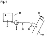
- FIG. 13 shows a schematic view of a device for injecting a reducing agent 18 stored in a tank 30, in particular an aqueous urea solution, into an exhaust line 26 of one in FIG Figure 1 internal combustion engine not shown, in particular a diesel engine.
- the reducing agent 18 is removed from the tank 30 and fed by a feed pump 7 under a pressure of 2 to 3 bar via a suitable fluid line 28 to an injection device 20 positioned directly on the exhaust line 26.
- the injection device 20 injects the reducing agent into the exhaust line 26 in order to supply it to the combustion gases 32 of the internal combustion engine (not shown in the figure) flowing through the exhaust line 26.
- Figure 2 shows a schematic sectional view of an exemplary embodiment of a tank 30 according to the invention for the reducing agent 18.
- the tank 30 has an outer housing 1 which encloses a tank volume 21.
- an insulating collar 2 rising in the shape of a dome towards the center of the tank volume 21 is formed, which within the insulating collar 2 delimits a first, outer partial volume 17 from the tank volume 21 outside the insulating collar 2.
- the insulating collar 2 has at least one opening 10 which creates a fluid connection between the first, outer partial volume 17 inside the insulating collar 2 and the tank volume 21 outside the insulating collar 2.
- the upper region 2a of the dome-shaped insulating collar 2, which is arranged essentially in the center of the tank volume 21, is funnel-shaped.
- a central opening 8 is formed, which likewise creates a connection between the first partial volume 17, which is enclosed by the insulating collar 2, and the outer tank volume 21.
- a functional unit 3 is arranged below the insulating collar 2 and is firmly connected to the tank bottom 15 of the housing 1, for example by a fluid-tight welded and / or screwed connection 14.
- the functional unit 3 delimits the first partial volume 17 formed below the dome-shaped insulating collar 2 in a fluid-tight manner downward.
- a pot-shaped, upwardly open inner container 4 is formed, which delimits a second, inner, upwardly open partial volume 16.
- the second, inner sub-volume 16 is in fluid connection with the first, outer sub-volume 17 via at least one fluid opening 9 formed in a wall 4 a of the cup-shaped inner container 4, so that an equally high fluid level is found in the first, outer sub-volume 17 and in the second, inner sub-volume 16 P sets.
- a fluid extraction device 6, 7 with a filter unit 6 and a pump 7 is arranged in the functional unit 3, which is designed and provided to remove the fluid from the second, inner sub-volume 16 in the pot-shaped inner container 4 and on an external injector 20, as shown in FIG Figure 1 shown is arranged on an exhaust line 26 to deliver.
- At least one first heating element 5 is also provided, which is designed to heat the fluid that is located in the second, inner partial volume 16 of the pot-shaped inner container 4 and, if necessary, to thaw it and / or to freeze the fluid in the second, inner partial volume 16 to prevent.
- the second heating element 11 is provided and designed to heat fluid that is located in the first, outer sub-volume 17 and, if necessary, to thaw it or to prevent the fluid from freezing in the first, outer sub-volume 17.
- the first groove 19a is on its (in the Figure 2 shown below) outside closed by a thermally insulating cover 13 in order to prevent heat from escaping on the underside of the housing 1.
- a second groove 19b running around the dome-shaped insulating collar 2 is formed in the radial direction outside the dome-shaped insulating collar 2 and the functional unit 3.
- at least one heating element 12 is arranged, which is designed to heat the fluid 18, which is located in the tank volume 21 outside the first and second partial volumes 17, 16, and if necessary to thaw it and possibly to freeze it prevent.
- This second, outer groove 19b is also closed on the underside of the tank container 1 by an insulating cover 13 in order to prevent heat loss on the underside of the housing 1.
- a vent valve 22 is formed, through which gases can escape from the tank volume 21 in order to prevent the creation of an overpressure in the tank volume 21.
- the at least one first heating element 5, which is arranged in the pot-shaped inner container 4, is first activated. Since the inner partial volume 16 to be heated is small, the first heating element 5 acts very quickly and effectively, so that frozen fluid in the inner partial volume 16 is thawed very quickly and is available as a liquid fluid that is available to the inner partial volume via the extraction device 6, 7 16 can be removed and fed to the injection device 20.
- the at least one first heating element 5 can be deactivated, and the at least one second heating element 11, which is arranged in the first groove 19a, is activated in order to fluid 18, which is in the outer Partial volume 17 is located, to be heated and thawed.
- Thawed fluid 18 from the outer partial volume 17 can flow into the inner partial volume 16 via the opening 9 in order to replace the fluid removed from the inner partial volume 16 by the fluid extraction device 6, 7.
- the insulating collar 2 prevents the heat introduced into the fluid by the second heating element 11 from being diverted into the large volume of the frozen fluid 18 in the outer tank volume 21, as a result of which the fluid 18 in the outer tank volume 21 would only be heated but not thawed.
- the insulating collar 2 also prevents fluid from the first or second partial volume 17, 16 from reaching the surface 18a of the frozen fluid 18 in the tank volume 21 and from freezing again there.
- Fluid thawed in the outer partial volume 17 heats the frozen fluid 18 in the tank volume 21 through the openings 10, which are formed in the insulating collar 2, and continues the thawing process starting from the areas around the openings 10.
- the thawing process is supported by the sloshing of the already thawed fluid.
- the funnel-shaped upper region 2a of the insulating collar 2 prevents fluid from escaping from the inner partial volume 16 into the outer tank volume 21 by sloshing movements. Through the opening formed in the funnel-shaped area 2a, however, sloshing liquid can get from the outer tank volume 21 into the inner sub-volume 16 and the inner sub-volume 16 and the outer sub-volume 17 can be vented, so that pressure differences between the outer tank volume 21 and the sub-volume 16, 17, can be prevented.
- the thawing of the frozen fluid 18 in the edge areas Y of the outer tank volume 21 can additionally be supported by an optional third heating element 12, which is inserted in the edge area 15a of the tank bottom 15 outside the insulating collar 2 in the tank bottom 15, and like the second heating element 11 can be designed as an electrical or water-based heating element 12.
- the second and possibly the third heating element 11, 12 basically form a surface heating that is electrically (as PTC or ohmic heating) or can be heated via cooling water. If the second and / or the third heating element 11, 12 are heated by cooling water, one (in the Figure 2 valve (not shown) may be provided in order to make it possible to deactivate the second or third heating element 11, 12 by closing the valve when a sufficient temperature of the fluid has been reached in the respective partial volume 17, 21.
- the grooves 19a, 19b can be filled with an electrically conductive plastic in order to implement a PTC heating element 11.
- the thawing behavior of the fluid 18 in the tank volume 21 can be controlled and regulated in a targeted manner via the cascade heating system proposed here with at least three heating elements 5, 11, 12.
- the outside temperature and / or the temperature of the fluid 18 in the tank which are measured by temperature sensors not shown in the figures, can be reference points for the regulation.
- a level sensor 23 can also be provided in the tank volume 21, which is designed to measure the level of the fluid 18 in the tank volume 21 and due to the presence or absence of sloshing movements of the fluid 18 which lead to fluctuations in the fluid level in the tank volume 21 to determine whether the fluid 18 in the tank volume 21 is frozen or not.
- the first heating element 5 ensures rapid availability of the amount of fluid stored in the inner partial volume 16. If the amount of fluid in the inner partial volume 16 has thawed, the first heating element 5 can be deactivated and the energy can instead be used to operate the second heating element 11.
- the second heating element 11 acts less quickly, but more sustainably.
- the heat can also reach the outermost regions of the tank volume 21 via the openings 10 formed in the insulating collar 2 and possibly a third heating element 12.
- first and the second partial volume 17, 16, in which the first and the second heating element 5, 11 are effective come into fluid communication with each other after a certain thawing time through the fluid openings 9, but against each other as well as are thermally insulated from the fluid 18 in the tank volume 21.
Description
Bei Kraftwagen mit Verbrennungsmotor muss aufgrund der Abgasgesetzgebung unter anderem der Schadstoff NOx reduziert werden. Eine Methode, die zur Anwendung kommt, ist das sogenannte SCR-Verfahren ("Selective Catalytic Reduction"), bei dem der Schadstoff NOx unter zu Hilfenahme von flüssigem Reduktionsmittel zu N2 und H2O reduziert wird.In the case of motor vehicles with internal combustion engines, the emissions legislation requires, among other things, the reduction of the pollutant NO x . One method that is used is the so-called SCR process ("Selective Catalytic Reduction"), in which the pollutant NO x is reduced to N 2 and H 2 O with the aid of a liquid reducing agent.
Dazu fördert eine Pumpe das Reduktionsmittel über eine Leitung von einem Tank zu einem Dosiermodul. Dabei wird das Medium entweder saugseitig oder druckseitig gefiltert.For this purpose, a pump conveys the reducing agent via a line from a tank to a metering module. The medium is filtered either on the suction side or on the pressure side.
Die in der Regel als Reduktionsmittel verwendete wässrige Harnstofflösung gefriert bei -11 °C und muss daher bei tiefen Temperaturen durch eine Heizung aufgetaut werden. Da eine punktförmige Heizung die Randbezirke des Tanks nicht oder nur schlecht erreicht, ist versucht worden, die Auftauleistung durch eine flächige Heizung, die in Bodennähe im Inneren des Tanks aufgespannt wird, zu vergrößern. Problematisch dabei ist, dass das gefrorene Reduktionsmittel, insbesondere bei einem vollem Tank, eine sehr große Eismasse darstellt. Die Heizung kann dann nur bei einer hohen Oberflächentemperatur das Eis im Bereich um die Heizung auftauen. Bei einer niedrigen Heizungstemperatur reicht die Heizleistung infolge des Wärmeabflusses in die große Eismasse nicht mehr aus, um das heizungsferne Eis zu schmelzen. Die große Eismasse erwärmt sich zwar etwas, für ein generelles Auftauen ist die Heizleistung jedoch zu gering.The aqueous urea solution, which is usually used as a reducing agent, freezes at -11 ° C and must therefore be thawed using a heater at low temperatures. Since a punctiform heater does not reach the peripheral areas of the tank or only reaches it poorly, attempts have been made to increase the thawing capacity by means of a flat heater that is set up close to the floor inside the tank. The problem here is that the frozen reducing agent, especially when the tank is full, represents a very large mass of ice. The heater can then only thaw the ice in the area around the heater when the surface temperature is high. At a low heating temperature, the heat output is no longer sufficient to melt the ice away from the heating due to the heat dissipation into the large mass of ice. The large mass of ice warms up a bit, but the heat output is too low for general thawing.
In
Eine Aufgabe der Erfindung ist es, einen Vorratstank, wie er in
Ein Vorratstank für ein Fluid, insbesondere für ein Reduktionsmittel zur Nachbehandlung von Abgasen eines Verbrennungsmotors, gemäß der Erfindung umfasst einen Außenbehälter, der ein Tankvolumen umschließt, wenigstens einen Innenbehälter, der ein inneres Teilvolumen des Tankvolumens begrenzt, wenigstens ein erstes Heizelement, das ausgebildet ist, um Fluid, das sich in dem inneren Teilvolumen befindet, zu erwärmen, sowie eine Entnahmevorrichtung, die es ermöglicht, Fluid aus dem Innenbehälter zu entnehmen. Der Innenbehälter ist von einem Isolierkragen umgeben, der ein äußeres Teilvolumen, das sich außerhalb des inneren Teilvolumens befindet, von dem Tankvolumen abgrenzt. Es ist auch wenigstens ein zweites Heizelement vorgesehen, das ausgebildet ist, um im Betrieb Fluid, das sich in dem zweiten Teilvolumen befindet, zu erwärmen. Das wenigstens eine zweite Heizelement ist in wenigstens einer Nut angeordnet, die im Boden des Vorratstanks ausgebildet ist.A storage tank for a fluid, in particular for a reducing agent for the aftertreatment of exhaust gases from an internal combustion engine, according to the invention comprises an outer container which encloses a tank volume, at least one inner container which delimits an inner partial volume of the tank volume, at least one first heating element which is designed, in order to heat fluid that is located in the inner partial volume, as well as a removal device that enables fluid to be removed from the inner container. The inner container is surrounded by an insulating collar which delimits an outer partial volume, which is located outside the inner partial volume, from the tank volume. At least one second heating element is also provided, which is designed to heat fluid that is located in the second partial volume during operation. The at least one second heating element is arranged in at least one groove which is formed in the bottom of the storage tank.
Das erste Heizelement und das zweite Heizelement bilden eine Kaskadenheizung, die es ermöglicht, das Auftauverhalten des in dem Tankvolumen gespeicherten Fluids gezielt zu steuern bzw. zu regeln und bereits nach einer sehr kurzen Auftauzeit eine erste Teilmenge aufgetauten Fluids zur Verfügung zu stellen. Eine im Boden ausgebildete Nut ermöglicht es, die Heizelemente effektiv, sicher und geschützt im Vorratstank zu installieren.The first heating element and the second heating element form a cascade heating system that makes it possible to specifically control or regulate the thawing behavior of the fluid stored in the tank volume and to provide a first partial amount of thawed fluid after a very short thawing time. A groove formed in the bottom enables the heating elements to be installed effectively, safely and securely in the storage tank.
Erfindungsgemäß ist der Innenbehälter, der das innere Teilvolumen umschließt, als nach oben offener Topf ausgebildet. Ein nach oben offener Topf kann einfach entlüftet werden und ermöglicht es, auf einfache Weise zusätzliches Fluid in das innere Teilvolumen einzubringen.According to the invention, the inner container, which encloses the inner partial volume, is designed as a pot that is open at the top. A pot that is open at the top can easily be vented and enables additional fluid to be introduced into the inner partial volume in a simple manner.
Erfindungsgemäß erstreckt sich der Isolierkragen wenigstens teilweise über den nach oben offenen Topf des Innenbehälters. Ein sich wenigstens teilweise über den nach oben offenen Topf des Innenbehälters erstreckender Isolierkragen verhindert, dass aufgrund von Schwappbewegungen Fluid aus dem inneren Teilvolumen austreten kann, wenn der Tank im Fahrbetrieb bewegt wird.According to the invention, the insulating collar extends at least partially over the upwardly open pot of the inner container. An insulating collar that extends at least partially over the pot of the inner container, which is open at the top, prevents fluid from escaping from the inner partial volume due to sloshing movements when the tank is moved while driving.
In einer Ausführungsform ist der Bereich des Isolierkragens, der sich über den nach oben offenen Topf des Innenbehälters erstreckt, trichterförmig ausgebildet. Auf diese Weise kann im Tankvolumen schwappendes Fluid im trichterförmigen Bereich des Isolierkragens gesammelt und dem inneren Teilvolumen zugeführt werden. Dazu ist im trichterförmigen Bereich des Isolierkragens über dem Innenbehälter wenigstens eine Öffnung ausgebildet.In one embodiment, the area of the insulating collar which extends over the pot of the inner container, which is open at the top, is funnel-shaped. In this way, fluid sloshing in the tank volume can be collected in the funnel-shaped area of the insulating collar and fed to the inner partial volume. For this purpose, at least one opening is formed in the funnel-shaped area of the insulating collar above the inner container.
In einer Ausführungsform ist wenigstens ein drittes Heizelement vorgesehen, das ausgebildet ist, um Fluid im Tankvolumen, das sich weder im inneren Teilvolumen noch im äußeren Teilvolumen befindet, zu erwärmen und ggf. aufzutauen. Das Auftauen des Fluids im Tankvolumen kann auf diese Weise unterstützt und beschleunigt werden.In one embodiment, at least one third heating element is provided which is designed to heat and, if necessary, thaw fluid in the tank volume that is neither in the inner sub-volume nor in the outer sub-volume. The thawing of the fluid in the tank volume can be supported and accelerated in this way.
In einer Ausführungsform ist auch das dritte Heizelement in wenigstens einer Nut, die im Boden des Vorratstanks ausgebildet ist, angeordnet. Eine im Boden ausgebildete Nut ermöglicht es, die Heizelemente effektiv, sicher und geschützt im Vorratstank zu installieren.In one embodiment, the third heating element is also arranged in at least one groove which is formed in the bottom of the storage tank. A groove formed in the bottom enables the heating elements to be installed effectively, safely and securely in the storage tank.
In einer Ausführungsform ist die Nut auf der Außenseite des Vorratstanks ausgebildet. Eine von außen im Boden des Vorratstanks ausgebildete Nut ermöglicht es darüber hinaus, die Heizelemente bei Bedarf einfach auszutauschen, ohne das Tankvolumen dafür entleeren zu müssen.In one embodiment, the groove is formed on the outside of the storage tank. A groove formed from the outside in the bottom of the storage tank also makes it possible to simply replace the heating elements if necessary without having to empty the tank volume.
In einer Ausführungsform ist die Nut auf der Außenseite des Vorratstanks durch eine thermisch isolierende Abdeckung verschlossen, um einen Wärmeverlust auf der Außenseite des Vorratstanks zu verhindern.In one embodiment, the groove on the outside of the storage tank is closed by a thermally insulating cover in order to prevent heat loss on the outside of the storage tank.
In einer Ausführungsform sind wenigstens der Innenbehälter, das wenigstens eine erste Heizelement und die Entnahmevorrichtung in einer Funktionseinheit integriert, die fluiddicht in den Vorratstank einsetzbar ist. Eine derartige Funktionseinheit, die fluiddicht in dem Außenbehälter des Vorratstanks einsetzbar ist, vereinfacht die Herstellung und Wartung des Vorratstanks. Insbesondere bei Bedarf einfach und schnell ausgetauscht werden, indem die komplette Funktionseinheit ausgewechselt wird.In one embodiment, at least the inner container, the at least one first heating element and the removal device are integrated in a functional unit which can be inserted into the storage tank in a fluid-tight manner. Such a functional unit, which can be used in a fluid-tight manner in the outer container of the storage tank, simplifies the manufacture and maintenance of the storage tank. In particular, they can be exchanged quickly and easily when required by exchanging the entire functional unit.
In einer Ausführungsform ist die Funktionseinheit mit dem Boden des Vorratstanks verschweißt und/oder verschraubt, um eine fluiddichte Verbindung zwischen der Funktionseinheit und dem Boden des Vorratstanks zu schaffen. Eine Verschweißung stellt eine sichere, fluiddichte Verbindung zur Verfügung. Eine Verschraubung ermöglicht es, die Funktionseinheit bei Bedarf einfach auszutauschen.In one embodiment, the functional unit is welded and / or screwed to the bottom of the storage tank in order to create a fluid-tight connection between the functional unit and the bottom of the storage tank. A weld provides a secure, fluid-tight connection. A screw connection makes it possible to simply exchange the functional unit if necessary.
Die Erfindung wird im Folgenden anhand der beigefügten Figuren näher erläutert.The invention is explained in more detail below with reference to the accompanying figures.
-
Figur 1 zeigt eine schematische Ansicht einer Vorrichtung zum Einspritzen eines in einem Tank gespeicherten Reduktionsmittels.Figure 1 shows a schematic view of a device for injecting a reducing agent stored in a tank. -
Figur 2 zeigt eine schematische Schnittansicht eines Ausführungsbeispiels eines erfindungsgemäßen Tanks 30.Figure 2 shows a schematic sectional view of an embodiment of atank 30 according to the invention.
Im Betrieb wird das Reduktionsmittel 18 dem Tank 30 entnommen und von einer Förderpumpe 7 unter einen Druck von 2 bis 3 bar über eine geeignete Fluidleitung 28 einer unmittelbar am Abgasstrang 26 positionierten Einspritzvorrichtung 20 zugeführt. Die Einspritzvorrichtung 20 spritzt das Reduktionsmittel im Betrieb in den Abgasstrang 26 ein, um es den durch den Abgasstrang 26 strömenden Verbrennungsgasen 32 des in der Figur nicht gezeigten Verbrennungsmotors zuzuführen.During operation, the reducing
Der Tank 30 hat ein äußeres Gehäuse 1, das ein Tankvolumen 21 umschließt.The
Von den Randbereichen 15a des Tankbodens 15 des Gehäuses 1 ausgehend ist ein zur Mitte des Tankvolumens 21 domförmig ansteigender Isolierkragen 2 ausgebildet, der innerhalb des Isolierkragens 2 ein erstes, äußeres Teilvolumen 17 vom Tankvolumen 21 außerhalb des Isolierkragens 2 abgrenzt. Der Isolierkragen 2 weist in seinem unteren Bereich in der Nähe des Tankbodens 15 wenigstens eine Öffnung 10 auf, die eine Fluidverbindung zwischen dem ersten, äußeren Teilvolumen 17 innerhalb des Isolierkragens 2 und dem Tankvolumen 21 außerhalb des Isolierkragens 2 schafft.Starting from the
Der obere, im Wesentlichen in der Mitte des Tankvolumens 21 angeordnete Bereich 2a des domförmig ausgebildeten Isolierkragens 2 ist trichterförmig ausgebildet. Im Zentrum des trichterförmigen Bereichs 2a ist eine Zentralöffnung 8 ausgebildet, die ebenfalls eine Verbindung zwischen dem ersten Teilvolumen 17, das von dem Isolierkragen 2 umschlossen wird, und dem äußeren Tankvolumen 21 schafft.The
Unterhalb des Isolierkragens 2 ist eine Funktionseinheit 3 angeordnet, die beispielsweise durch eine fluiddichte Schweiß- und/oder Schraubverbindung 14 fest mit dem Tankboden 15 des Gehäuses 1 verbunden ist. Die Funktionseinheit 3 begrenzt das unterhalb des domförmigen Isolierkragens 2 ausgebildete erste Teilvolumen 17 fluiddicht nach unten.A
In einem mittleren Bereich der Funktionseinheit 3 ist unterhalb des trichterförmigen Bereichs 2a des Isolierkragens 2 ein topfförmiger, nach oben offener Innenbehälter 4 ausgebildet, der ein zweites, inneres, nach oben offenes Teilvolumen 16 begrenzt.In a central area of the
Das zweite, innere Teilvolumen 16 steht über wenigstens eine in einer Wand 4a des topfförmigen Innenbehälters 4 ausgebildete Fluidöffnung 9 in Fluidverbindung mit dem ersten, äußeren Teilvolumen 17, so dass sich im ersten, äußeren Teilvolumen 17 und im zweiten, inneren Teilvolumen 16 ein gleichhoher Fluidpegel P einstellt.The second,
Unterhalb des topfförmig ausgebildeten Innenbehälters 4 ist in der Funktionseinheit 3 eine Fluidentnahmevorrichtung 6, 7 mit einer Filtereinheit 6 und einer Pumpe 7 angeordnet, die ausgebildet und vorgesehen ist, um das Fluid aus dem zweiten, inneren Teilvolumen 16 im topfförmigen Innenbehälter 4 zu entnehmen und an eine externe Einspritzvorrichtung 20, die wie in der
Im topfförmigen Innenbehälter 4 ist auch wenigstens ein erstes Heizelement 5 vorgesehen, das ausgebildet ist, um das Fluid, das sich in dem zweiten, inneren Teilvolumen 16 des topfförmigen Innenbehälters 4 befindet, zu erwärmen und ggf. aufzutauen und/oder ein Einfrieren des Fluids in dem zweiten, inneren Teilvolumen 16 zu verhindern.In the pot-shaped
In radialer Richtung außerhalb des topfförmigen Innenbehälters 4 ist im Boden der Funktionseinheit 3 auf der äußeren, in der
Die erste Nut 19a ist auf ihrer (in der
Auch wenn in der
Eine um den domförmig ausgebildeten Isolierkragen 2 umlaufende zweite Nut 19b ist in radialer Richtung außerhalb des domförmigen Isolierkragens 2 und der Funktionseinheit 3 ausgebildet. In der zweiten Nut 19b ist wenigstens ein Heizelement 12 angeordnet, das ausgebildet ist, um das Fluid 18, das sich im Tankvolumen 21 außerhalb des ersten und des zweiten Teilvolumens 17, 16 befindet, zu erwärmen und ggf. aufzutauen und ggf. ein Einfrieren zu verhindern. Auch diese zweite, äußere Nut 19b ist auf der Unterseite des Tankbehälters 1 durch eine isolierende Abdeckung 13 verschlossen, um einen Wärmeverlust auf der Unterseite des Gehäuses 1 zu verhindern.A
Im oberen Bereich des Tankbehälters 1 ist ein Entlüftungsventil 22 ausgebildet, durch das Gase aus dem Tankvolumen 21 entweichen können, um das Entstehen eines Überdrucks im Tankvolumen 21 zu verhindern.In the upper region of the tank container 1, a
Um gefrorenes Fluid 18 aufzutauen, wird zunächst das wenigstens eine erste Heizelement 5, das im topfförmig ausgebildeten Innenbehälter 4 angeordnet ist, aktiviert. Da das zu erwärmende innere Teilvolumen 16 klein ist, wirkt das erste Heizelement 5 sehr schnell und effektiv, so dass gefrorenes Fluid im inneren Teilvolumen 16 sehr schnell aufgetaut wird und als flüssiges Fluid zur Verfügung steht, dass über die Entnahmevorrichtung 6, 7 dem inneren Teilvolumen 16 entnommen und der Einspritzvorrichtung 20 zugeführt werden kann.In order to thaw
Nach dem das Fluid im inneren Teilvolumen 16 aufgetaut worden ist, kann das wenigstens eine erste Heizelement 5 deaktiviert werden, und das wenigstens eine zweite Heizelement 11, das in der ersten Nut 19a angeordnet ist, wird aktiviert, um Fluid 18, das sich im äußeren Teilvolumen 17 befindet, zu erwärmen und aufzutauen.After the fluid in the inner
Aufgetautes Fluid 18 aus dem äußeren Teilvolumen 17 kann über die Öffnung 9 in das innere Teilvolumen 16 strömen, um das von der Fluidentnahmevorrichtung 6, 7 aus dem inneren Teilvolumen 16 entnommene Fluid zu ersetzen.Thawed fluid 18 from the outer
Der Isolierkragen 2 verhindert, dass die von dem zweiten Heizelement 11 in das Fluid eingebrachte Wärme in das große Volumen des gefrorenen Fluid 18 im äußeren Tankvolumen 21 abgeleitet wird, wodurch das Fluid 18 im äußeren Tankvolumen 21 nur erwärmt, jedoch nicht aufgetaut werden würde.The insulating
Der Isolierkragen 2 verhindert außerdem, dass Fluid aus dem ersten oder zweiten Teilvolumen 17, 16 auf die Oberfläche 18a des gefrorenen Fluids 18 im Tankvolumen 21 gelangt und dort erneut gefriert.The insulating
Im äußeren Teilvolumen 17 aufgetautes Fluid erwärmt durch die Öffnungen 10, die in dem Isolierkragen 2 ausgebildet sind, punktuell das gefrorene Fluid 18 im Tankvolumen 21 und setzt den Auftauvorgang ausgehend von den Bereichen um die Öffnungen 10 fort. Bei einer Bewegung des Tankbehälters 1 im Fahrbetrieb wird der Auftauvorgang durch Schwappen des bereits aufgetauten Fluids unterstützt.Fluid thawed in the outer
Der trichterförmig ausgebildete obere Bereich 2a des Isolierkragens 2 verhindert, dass Fluid aus dem inneren Teilvolumen 16 durch Schwappbewegungen in das äußere Tankvolumen 21 entweichen kann. Durch die im trichterförmigen Bereich 2a ausgebildete Öffnung kann jedoch schwappende Flüssigkeit aus dem äußeren Tankvolumen 21 in das innere Teilvolumen 16 gelangen und das innere Teilvolumen 16 und das äußere Teilvolumen 17 können entlüftet werden, so dass Druckunterschiede zwischen dem äußeren Tankvolumen 21 und dem Teilvolumen 16, 17, verhindert werden können.The funnel-shaped
Das Auftauen des gefrorenen Fluids 18 in den Randbereichen Y des äußeren Tankvolumens 21 kann zusätzlich durch ein optionales drittes Heizelement 12 unterstützt werden, das im Randbereich 15a des Tankbodens 15 außerhalb des Isolierkragens 2 in den Tankboden 15 eingefügt ist, und so wie das zweite Heizelement 11 als elektrisches oder wasserbasiertes Heizelement 12 ausgebildet sein kann.The thawing of the
Das zweite und ggf. das dritte Heizelement 11, 12 bilden im Grunde eine Flächenheizung, die elektrisch (als PTC- oder als Ohmsche Heizung) oder über Kühlwasser beheizt werden kann. Werden das zweite und/oder das dritte Heizelement 11, 12 über Kühlwasser beheizt, so kann jeweils ein (in der
Alternativ können die Nuten 19a, 19b mit einem elektrisch leitenden Kunststoff gefüllt sein, um ein PTC- Heizelement 11 zu realisieren.Alternatively, the
Über die hier vorgeschlagene Kaskadenheizung mit wenigstens drei Heizelementen 5, 11, 12 kann das Auftauverhalten des Fluids 18 im Tankvolumen 21 gezielt gesteuert und geregelt werden. Anhaltspunkte für die Regelung können die Außentemperatur und/oder die Temperatur des Fluids 18 im Tank sein, die über, in den Figuren nicht gezeigte, Temperatursensoren gemessen werden. Alternativ oder zusätzlich kann im Tankvolumen 21 auch ein Niveausensor 23 vorgesehen sein, der ausgebildet ist, um das Niveau des Fluids 18 im Tankvolumen 21 zu messen und aufgrund vorhandener bzw. nicht vorhandener Schwappbewegungen des Fluids 18, die zu Schwankungen des Fluidniveaus im Tankvolumen 21 führen, festzustellen, ob das Fluid 18 im Tankvolumen 21 gefroren ist oder nicht.The thawing behavior of the fluid 18 in the
Das erste Heizelement 5 sorgt für eine schnelle Verfügbarkeit der im inneren Teilvolumen 16 gespeicherten Fluidmenge. Ist die Fluidmenge im inneren Teilvolumen 16 aufgetaut, so kann das erste Heizelement 5 deaktiviert, und die Energie stattdessen zum Betreiben des zweiten Heizelements 11 verwendet werden. Das zweite Heizelement 11 wirkt weniger schnell, dafür jedoch umso nachhaltiger. Über die in dem Isolierkragen 2 ausgebildeten Öffnungen 10 und ggf. ein drittes Heizelement 12 kann die Wärme auch die äußersten Bereiche des Tankvolumens 21 erreichen.The
Für die Funktion der Erfindung ist von Bedeutung, dass das erste und das zweite Teilvolumen 17, 16, in denen das erste und das zweite Heizelement 5, 11 wirksam sind, nach einer gewissen Auftauzeit durch die Fluidöffnungen 9 in Fluidverbindung miteinander treten dabei aber gegeneinander sowie gegen das Fluid 18 im Tankvolumen 21 thermisch isoliert sind.For the function of the invention it is important that the first and the second
Claims (8)
- Supply tank for a fluid (18), in particular a reducing agent for the aftertreatment of exhaust gases of an internal combustion engine, comprising an outer container (1) which encloses a tank volume (21), at least one inner container (4) which sections off an inner part volume (16) from the tank volume (21),
at least one first heating element (5) which is configured to heat fluid (18) which is situated in the inner part volume (16); and
a removal apparatus (7) which is configured to remove fluid (18) from the inner container (4);
the inner container (4) being surrounded by an insulating collar (2) which sections off an outer part volume (17) from the tank volume (21);
at least one second heating element (11) being provided which is configured to heat, during operation, fluid (18) which is situated in the outer part volume (17); the at least one inner container (4) being configured as a pot which is open at the top,
characterized in that- the at least one second heating element (11, 12) is arranged in at least one groove (19a, 19b) which is configured in the bottom (15) of the supply tank,- the insulating collar (2) extending at least partially beyond the at least one inner container (4). - Supply tank according to Claim 1, that region (2a) of the insulating collar (2) which extends beyond the at least one inner container (4) being of funnel-shaped configuration.
- Supply tank according to Claim 1 or 2, at least one opening (8) being configured in that region (2a) of the insulating collar (2) which extends beyond the at least one inner container (4).
- Supply tank according to one of the preceding claims, at least one third heating element (11) being provided which is configured to heat, during operation, fluid (18) which is situated the tank volume (21) of the outer container (1) outside the inner part volume (16) and outside the outer part volume (17).
- Supply tank according to Claim 4, the third heating element (11, 12) being arranged in at least one groove (19a, 19b) which is configured in the bottom (15) of the supply tank.
- Supply tank according to one of the preceding claims, at least one groove (19a, 19b) being configured on the outer side of the bottom (15) of the supply tank and being closed by way of a thermally insulating cover (13) .
- Supply tank according to one of the preceding claims, the inner container (4), the at least one first heating element (5) and the removal apparatus (7) being integrated into one functional unit (3).
- Supply tank according to Claim 7, the functional unit (3) being welded or screwed to the bottom (15) of the supply tank.
Applications Claiming Priority (2)
| Application Number | Priority Date | Filing Date | Title |
|---|---|---|---|
| DE102013211760.4A DE102013211760A1 (en) | 2013-06-21 | 2013-06-21 | Storage tank with heating device |
| PCT/EP2014/058878 WO2014202268A1 (en) | 2013-06-21 | 2014-04-30 | Storage tank with a heating device |
Publications (3)
| Publication Number | Publication Date |
|---|---|
| EP3011153A1 EP3011153A1 (en) | 2016-04-27 |
| EP3011153B1 EP3011153B1 (en) | 2018-01-10 |
| EP3011153B2 true EP3011153B2 (en) | 2021-03-03 |
Family
ID=50678175
Family Applications (1)
| Application Number | Title | Priority Date | Filing Date |
|---|---|---|---|
| EP14721828.3A Active EP3011153B2 (en) | 2013-06-21 | 2014-04-30 | Storage tank with a heating device |
Country Status (3)
| Country | Link |
|---|---|
| EP (1) | EP3011153B2 (en) |
| DE (1) | DE102013211760A1 (en) |
| WO (1) | WO2014202268A1 (en) |
Families Citing this family (8)
| Publication number | Priority date | Publication date | Assignee | Title |
|---|---|---|---|---|
| DE102015214401A1 (en) * | 2015-07-29 | 2017-02-02 | Robert Bosch Gmbh | tank system |
| WO2017097808A1 (en) * | 2015-12-10 | 2017-06-15 | Continental Automotive Gmbh | Tank system for a reducing agent |
| DE102016202718A1 (en) * | 2016-02-23 | 2017-08-24 | Bayerische Motoren Werke Aktiengesellschaft | Heatable container for a fluid |
| DE102016013085A1 (en) | 2016-11-02 | 2017-05-18 | Daimler Ag | Tank device for an internal combustion engine, in particular a motor vehicle |
| DE102016121684A1 (en) * | 2016-11-11 | 2018-05-17 | Dbk David + Baader Gmbh | Heating module for a melting tank, and melting tank with the heating module |
| CN108194173A (en) * | 2018-01-14 | 2018-06-22 | 亚普汽车部件股份有限公司 | Vehicle reducing agent storage box heating unit |
| DE102018206584A1 (en) * | 2018-04-27 | 2019-10-31 | Bayerische Motoren Werke Aktiengesellschaft | Equipment container of a motor vehicle for storing a resource and motor vehicle |
| DE102018210455A1 (en) * | 2018-06-27 | 2020-01-02 | Robert Bosch Gmbh | tank system |
Citations (2)
| Publication number | Priority date | Publication date | Assignee | Title |
|---|---|---|---|---|
| DE202005019499U1 (en) † | 2005-12-14 | 2006-02-09 | Man Nutzfahrzeuge Ag | Heating system for a vehicle tank, containing a solution of urea and water, has a tube to take a heat carrier flow pressed into a serpentine groove at the outer side of a tank wall |
| WO2011086038A1 (en) † | 2010-01-13 | 2011-07-21 | Emitec Gesellschaft Für Emissionstechnologie Mbh | Device having a tank and a delivery unit for reductants |
Family Cites Families (4)
| Publication number | Priority date | Publication date | Assignee | Title |
|---|---|---|---|---|
| JP4431482B2 (en) | 2004-11-16 | 2010-03-17 | 日野自動車株式会社 | Urea water storage device |
| DE102007061808A1 (en) * | 2007-12-19 | 2009-06-25 | Dbk David + Baader Gmbh | Tank removal system |
| DE102009046969A1 (en) | 2009-11-23 | 2011-05-26 | Robert Bosch Gmbh | Storage tank for a reducing agent |
| DE102011108213A1 (en) | 2011-07-21 | 2013-01-24 | Audi Ag | Heatable reducing agent tank for supplying aqueous urea solution to selective catalytic reduction exhaust gas cleaning system for internal combustion engine of vehicle, has chamber flow-technically coupled with removal point |
-
2013
- 2013-06-21 DE DE102013211760.4A patent/DE102013211760A1/en not_active Withdrawn
-
2014
- 2014-04-30 EP EP14721828.3A patent/EP3011153B2/en active Active
- 2014-04-30 WO PCT/EP2014/058878 patent/WO2014202268A1/en active Application Filing
Patent Citations (2)
| Publication number | Priority date | Publication date | Assignee | Title |
|---|---|---|---|---|
| DE202005019499U1 (en) † | 2005-12-14 | 2006-02-09 | Man Nutzfahrzeuge Ag | Heating system for a vehicle tank, containing a solution of urea and water, has a tube to take a heat carrier flow pressed into a serpentine groove at the outer side of a tank wall |
| WO2011086038A1 (en) † | 2010-01-13 | 2011-07-21 | Emitec Gesellschaft Für Emissionstechnologie Mbh | Device having a tank and a delivery unit for reductants |
Also Published As
| Publication number | Publication date |
|---|---|
| DE102013211760A1 (en) | 2014-12-24 |
| WO2014202268A1 (en) | 2014-12-24 |
| EP3011153B1 (en) | 2018-01-10 |
| EP3011153A1 (en) | 2016-04-27 |
Similar Documents
| Publication | Publication Date | Title |
|---|---|---|
| EP3011153B2 (en) | Storage tank with a heating device | |
| EP2475853B1 (en) | Feeding device for a reducing agent | |
| DE112006001892B4 (en) | heating system | |
| EP2707579B1 (en) | Supply tank and functional unit therefor | |
| DE102011108213A1 (en) | Heatable reducing agent tank for supplying aqueous urea solution to selective catalytic reduction exhaust gas cleaning system for internal combustion engine of vehicle, has chamber flow-technically coupled with removal point | |
| WO2017137101A1 (en) | System for storing an auxiliary liquid and supplying same to an internal combustion engine | |
| DE102009000094A1 (en) | Tank for receiving an aqueous solution | |
| WO2015185568A1 (en) | Device for providing a liquid additive | |
| EP2785990B1 (en) | Device for providing reducing agent | |
| DE102012020040B4 (en) | Device for storing and conveying an aqueous additive | |
| DE102011057052A1 (en) | UREA HEATING SYSTEM AND HEATING PROCEDURES THEREFOR / FOR | |
| DE10256444A1 (en) | Fuel filter assembly with an integrated fuel heater | |
| DE112011104704T5 (en) | An integrated SCR dosing and injection system | |
| EP3164581A1 (en) | Heating unit for a device for accommodating and providing liquid reducing agent | |
| EP2029866B1 (en) | Method and device for cleaning valves | |
| EP3211191B1 (en) | Heatable container for a fluid | |
| EP3478946B1 (en) | Metering device for metering a reductant liquid and method for operating a metering device | |
| EP3384138B1 (en) | Reduction agent system with a heatable tank and use of a heating device for heating of a reduction agent tank | |
| DE102014015714A1 (en) | Heating device for a device for receiving and providing liquid reducing agent | |
| DE102018208091A1 (en) | Container for a freezable fluid for use in a motor vehicle | |
| WO2011086023A1 (en) | Device having an injector for a liquid reducing agent | |
| WO2019029881A1 (en) | Tank device for exhaust gas post-treatment system | |
| DE102013210740A1 (en) | Extraction device, tank device | |
| EP3652012B1 (en) | Fluid container for a motor vehicle | |
| DE102018203204A1 (en) | Heating device, tank module and liquid tank |
Legal Events
| Date | Code | Title | Description |
|---|---|---|---|
| PUAI | Public reference made under article 153(3) epc to a published international application that has entered the european phase |
Free format text: ORIGINAL CODE: 0009012 |
|
| 17P | Request for examination filed |
Effective date: 20160121 |
|
| AK | Designated contracting states |
Kind code of ref document: A1 Designated state(s): AL AT BE BG CH CY CZ DE DK EE ES FI FR GB GR HR HU IE IS IT LI LT LU LV MC MK MT NL NO PL PT RO RS SE SI SK SM TR |
|
| AX | Request for extension of the european patent |
Extension state: BA ME |
|
| DAX | Request for extension of the european patent (deleted) | ||
| STAA | Information on the status of an ep patent application or granted ep patent |
Free format text: STATUS: EXAMINATION IS IN PROGRESS |
|
| 17Q | First examination report despatched |
Effective date: 20170203 |
|
| GRAP | Despatch of communication of intention to grant a patent |
Free format text: ORIGINAL CODE: EPIDOSNIGR1 |
|
| STAA | Information on the status of an ep patent application or granted ep patent |
Free format text: STATUS: GRANT OF PATENT IS INTENDED |
|
| INTG | Intention to grant announced |
Effective date: 20171016 |
|
| GRAS | Grant fee paid |
Free format text: ORIGINAL CODE: EPIDOSNIGR3 |
|
| GRAA | (expected) grant |
Free format text: ORIGINAL CODE: 0009210 |
|
| STAA | Information on the status of an ep patent application or granted ep patent |
Free format text: STATUS: THE PATENT HAS BEEN GRANTED |
|
| AK | Designated contracting states |
Kind code of ref document: B1 Designated state(s): AL AT BE BG CH CY CZ DE DK EE ES FI FR GB GR HR HU IE IS IT LI LT LU LV MC MK MT NL NO PL PT RO RS SE SI SK SM TR |
|
| REG | Reference to a national code |
Ref country code: CH Ref legal event code: EP Ref country code: AT Ref legal event code: REF Ref document number: 962658 Country of ref document: AT Kind code of ref document: T Effective date: 20180115 |
|
| REG | Reference to a national code |
Ref country code: IE Ref legal event code: FG4D Free format text: LANGUAGE OF EP DOCUMENT: GERMAN |
|
| REG | Reference to a national code |
Ref country code: DE Ref legal event code: R096 Ref document number: 502014006894 Country of ref document: DE |
|
| REG | Reference to a national code |
Ref country code: FR Ref legal event code: PLFP Year of fee payment: 5 |
|
| REG | Reference to a national code |
Ref country code: NL Ref legal event code: MP Effective date: 20180110 |
|
| PG25 | Lapsed in a contracting state [announced via postgrant information from national office to epo] |
Ref country code: NL Free format text: LAPSE BECAUSE OF FAILURE TO SUBMIT A TRANSLATION OF THE DESCRIPTION OR TO PAY THE FEE WITHIN THE PRESCRIBED TIME-LIMIT Effective date: 20180110 |
|
| PG25 | Lapsed in a contracting state [announced via postgrant information from national office to epo] |
Ref country code: LT Free format text: LAPSE BECAUSE OF FAILURE TO SUBMIT A TRANSLATION OF THE DESCRIPTION OR TO PAY THE FEE WITHIN THE PRESCRIBED TIME-LIMIT Effective date: 20180110 Ref country code: CY Free format text: LAPSE BECAUSE OF FAILURE TO SUBMIT A TRANSLATION OF THE DESCRIPTION OR TO PAY THE FEE WITHIN THE PRESCRIBED TIME-LIMIT Effective date: 20180110 Ref country code: FI Free format text: LAPSE BECAUSE OF FAILURE TO SUBMIT A TRANSLATION OF THE DESCRIPTION OR TO PAY THE FEE WITHIN THE PRESCRIBED TIME-LIMIT Effective date: 20180110 Ref country code: ES Free format text: LAPSE BECAUSE OF FAILURE TO SUBMIT A TRANSLATION OF THE DESCRIPTION OR TO PAY THE FEE WITHIN THE PRESCRIBED TIME-LIMIT Effective date: 20180110 Ref country code: NO Free format text: LAPSE BECAUSE OF FAILURE TO SUBMIT A TRANSLATION OF THE DESCRIPTION OR TO PAY THE FEE WITHIN THE PRESCRIBED TIME-LIMIT Effective date: 20180410 Ref country code: HR Free format text: LAPSE BECAUSE OF FAILURE TO SUBMIT A TRANSLATION OF THE DESCRIPTION OR TO PAY THE FEE WITHIN THE PRESCRIBED TIME-LIMIT Effective date: 20180110 |
|
| PG25 | Lapsed in a contracting state [announced via postgrant information from national office to epo] |
Ref country code: RS Free format text: LAPSE BECAUSE OF FAILURE TO SUBMIT A TRANSLATION OF THE DESCRIPTION OR TO PAY THE FEE WITHIN THE PRESCRIBED TIME-LIMIT Effective date: 20180110 Ref country code: SE Free format text: LAPSE BECAUSE OF FAILURE TO SUBMIT A TRANSLATION OF THE DESCRIPTION OR TO PAY THE FEE WITHIN THE PRESCRIBED TIME-LIMIT Effective date: 20180110 Ref country code: LV Free format text: LAPSE BECAUSE OF FAILURE TO SUBMIT A TRANSLATION OF THE DESCRIPTION OR TO PAY THE FEE WITHIN THE PRESCRIBED TIME-LIMIT Effective date: 20180110 Ref country code: IS Free format text: LAPSE BECAUSE OF FAILURE TO SUBMIT A TRANSLATION OF THE DESCRIPTION OR TO PAY THE FEE WITHIN THE PRESCRIBED TIME-LIMIT Effective date: 20180510 Ref country code: BG Free format text: LAPSE BECAUSE OF FAILURE TO SUBMIT A TRANSLATION OF THE DESCRIPTION OR TO PAY THE FEE WITHIN THE PRESCRIBED TIME-LIMIT Effective date: 20180410 Ref country code: PL Free format text: LAPSE BECAUSE OF FAILURE TO SUBMIT A TRANSLATION OF THE DESCRIPTION OR TO PAY THE FEE WITHIN THE PRESCRIBED TIME-LIMIT Effective date: 20180110 Ref country code: GR Free format text: LAPSE BECAUSE OF FAILURE TO SUBMIT A TRANSLATION OF THE DESCRIPTION OR TO PAY THE FEE WITHIN THE PRESCRIBED TIME-LIMIT Effective date: 20180411 |
|
| PG25 | Lapsed in a contracting state [announced via postgrant information from national office to epo] |
Ref country code: MT Free format text: LAPSE BECAUSE OF FAILURE TO SUBMIT A TRANSLATION OF THE DESCRIPTION OR TO PAY THE FEE WITHIN THE PRESCRIBED TIME-LIMIT Effective date: 20180110 |
|
| REG | Reference to a national code |
Ref country code: DE Ref legal event code: R026 Ref document number: 502014006894 Country of ref document: DE |
|
| PLBI | Opposition filed |
Free format text: ORIGINAL CODE: 0009260 |
|
| PLAX | Notice of opposition and request to file observation + time limit sent |
Free format text: ORIGINAL CODE: EPIDOSNOBS2 |
|
| PG25 | Lapsed in a contracting state [announced via postgrant information from national office to epo] |
Ref country code: AL Free format text: LAPSE BECAUSE OF FAILURE TO SUBMIT A TRANSLATION OF THE DESCRIPTION OR TO PAY THE FEE WITHIN THE PRESCRIBED TIME-LIMIT Effective date: 20180110 Ref country code: RO Free format text: LAPSE BECAUSE OF FAILURE TO SUBMIT A TRANSLATION OF THE DESCRIPTION OR TO PAY THE FEE WITHIN THE PRESCRIBED TIME-LIMIT Effective date: 20180110 Ref country code: EE Free format text: LAPSE BECAUSE OF FAILURE TO SUBMIT A TRANSLATION OF THE DESCRIPTION OR TO PAY THE FEE WITHIN THE PRESCRIBED TIME-LIMIT Effective date: 20180110 Ref country code: IT Free format text: LAPSE BECAUSE OF FAILURE TO SUBMIT A TRANSLATION OF THE DESCRIPTION OR TO PAY THE FEE WITHIN THE PRESCRIBED TIME-LIMIT Effective date: 20180110 |
|
| 26 | Opposition filed |
Opponent name: EICHENAUER HEIZELEMENTE GMBH & CO. KG Effective date: 20181008 |
|
| PG25 | Lapsed in a contracting state [announced via postgrant information from national office to epo] |
Ref country code: SK Free format text: LAPSE BECAUSE OF FAILURE TO SUBMIT A TRANSLATION OF THE DESCRIPTION OR TO PAY THE FEE WITHIN THE PRESCRIBED TIME-LIMIT Effective date: 20180110 Ref country code: SM Free format text: LAPSE BECAUSE OF FAILURE TO SUBMIT A TRANSLATION OF THE DESCRIPTION OR TO PAY THE FEE WITHIN THE PRESCRIBED TIME-LIMIT Effective date: 20180110 Ref country code: DK Free format text: LAPSE BECAUSE OF FAILURE TO SUBMIT A TRANSLATION OF THE DESCRIPTION OR TO PAY THE FEE WITHIN THE PRESCRIBED TIME-LIMIT Effective date: 20180110 Ref country code: MC Free format text: LAPSE BECAUSE OF FAILURE TO SUBMIT A TRANSLATION OF THE DESCRIPTION OR TO PAY THE FEE WITHIN THE PRESCRIBED TIME-LIMIT Effective date: 20180110 Ref country code: CZ Free format text: LAPSE BECAUSE OF FAILURE TO SUBMIT A TRANSLATION OF THE DESCRIPTION OR TO PAY THE FEE WITHIN THE PRESCRIBED TIME-LIMIT Effective date: 20180110 |
|
| REG | Reference to a national code |
Ref country code: CH Ref legal event code: PL |
|
| REG | Reference to a national code |
Ref country code: BE Ref legal event code: MM Effective date: 20180430 |
|
| GBPC | Gb: european patent ceased through non-payment of renewal fee |
Effective date: 20180430 |
|
| REG | Reference to a national code |
Ref country code: IE Ref legal event code: MM4A |
|
| PG25 | Lapsed in a contracting state [announced via postgrant information from national office to epo] |
Ref country code: LU Free format text: LAPSE BECAUSE OF NON-PAYMENT OF DUE FEES Effective date: 20180430 |
|
| PG25 | Lapsed in a contracting state [announced via postgrant information from national office to epo] |
Ref country code: CH Free format text: LAPSE BECAUSE OF NON-PAYMENT OF DUE FEES Effective date: 20180430 Ref country code: SI Free format text: LAPSE BECAUSE OF FAILURE TO SUBMIT A TRANSLATION OF THE DESCRIPTION OR TO PAY THE FEE WITHIN THE PRESCRIBED TIME-LIMIT Effective date: 20180110 Ref country code: BE Free format text: LAPSE BECAUSE OF NON-PAYMENT OF DUE FEES Effective date: 20180430 Ref country code: GB Free format text: LAPSE BECAUSE OF NON-PAYMENT OF DUE FEES Effective date: 20180430 Ref country code: LI Free format text: LAPSE BECAUSE OF NON-PAYMENT OF DUE FEES Effective date: 20180430 |
|
| PLBB | Reply of patent proprietor to notice(s) of opposition received |
Free format text: ORIGINAL CODE: EPIDOSNOBS3 |
|
| PG25 | Lapsed in a contracting state [announced via postgrant information from national office to epo] |
Ref country code: IE Free format text: LAPSE BECAUSE OF NON-PAYMENT OF DUE FEES Effective date: 20180430 |
|
| PG25 | Lapsed in a contracting state [announced via postgrant information from national office to epo] |
Ref country code: TR Free format text: LAPSE BECAUSE OF FAILURE TO SUBMIT A TRANSLATION OF THE DESCRIPTION OR TO PAY THE FEE WITHIN THE PRESCRIBED TIME-LIMIT Effective date: 20180110 |
|
| RAP2 | Party data changed (patent owner data changed or rights of a patent transferred) |
Owner name: ROBERT BOSCH GMBH |
|
| PG25 | Lapsed in a contracting state [announced via postgrant information from national office to epo] |
Ref country code: PT Free format text: LAPSE BECAUSE OF FAILURE TO SUBMIT A TRANSLATION OF THE DESCRIPTION OR TO PAY THE FEE WITHIN THE PRESCRIBED TIME-LIMIT Effective date: 20180110 |
|
| PG25 | Lapsed in a contracting state [announced via postgrant information from national office to epo] |
Ref country code: MK Free format text: LAPSE BECAUSE OF NON-PAYMENT OF DUE FEES Effective date: 20180110 Ref country code: HU Free format text: LAPSE BECAUSE OF FAILURE TO SUBMIT A TRANSLATION OF THE DESCRIPTION OR TO PAY THE FEE WITHIN THE PRESCRIBED TIME-LIMIT; INVALID AB INITIO Effective date: 20140430 |
|
| PGFP | Annual fee paid to national office [announced via postgrant information from national office to epo] |
Ref country code: FR Payment date: 20200421 Year of fee payment: 7 |
|
| REG | Reference to a national code |
Ref country code: AT Ref legal event code: MM01 Ref document number: 962658 Country of ref document: AT Kind code of ref document: T Effective date: 20190430 |
|
| PG25 | Lapsed in a contracting state [announced via postgrant information from national office to epo] |
Ref country code: AT Free format text: LAPSE BECAUSE OF NON-PAYMENT OF DUE FEES Effective date: 20190430 |
|
| PUAH | Patent maintained in amended form |
Free format text: ORIGINAL CODE: 0009272 |
|
| STAA | Information on the status of an ep patent application or granted ep patent |
Free format text: STATUS: PATENT MAINTAINED AS AMENDED |
|
| 27A | Patent maintained in amended form |
Effective date: 20210303 |
|
| AK | Designated contracting states |
Kind code of ref document: B2 Designated state(s): AL AT BE BG CH CY CZ DE DK EE ES FI FR GB GR HR HU IE IS IT LI LT LU LV MC MK MT NL NO PL PT RO RS SE SI SK SM TR |
|
| REG | Reference to a national code |
Ref country code: DE Ref legal event code: R102 Ref document number: 502014006894 Country of ref document: DE |
|
| PG25 | Lapsed in a contracting state [announced via postgrant information from national office to epo] |
Ref country code: FR Free format text: LAPSE BECAUSE OF NON-PAYMENT OF DUE FEES Effective date: 20210430 |
|
| PGFP | Annual fee paid to national office [announced via postgrant information from national office to epo] |
Ref country code: DE Payment date: 20230627 Year of fee payment: 10 |