EP3011142B1 - Carter intermédiaire amélioré de turbomachine et ensemble d'entrainement de boitier d'accessoire - Google Patents
Carter intermédiaire amélioré de turbomachine et ensemble d'entrainement de boitier d'accessoire Download PDFInfo
- Publication number
- EP3011142B1 EP3011142B1 EP14738879.7A EP14738879A EP3011142B1 EP 3011142 B1 EP3011142 B1 EP 3011142B1 EP 14738879 A EP14738879 A EP 14738879A EP 3011142 B1 EP3011142 B1 EP 3011142B1
- Authority
- EP
- European Patent Office
- Prior art keywords
- hub
- radial
- gearbox
- casing
- radial shaft
- Prior art date
- Legal status (The legal status is an assumption and is not a legal conclusion. Google has not performed a legal analysis and makes no representation as to the accuracy of the status listed.)
- Active
Links
Images



Classifications
-
- F—MECHANICAL ENGINEERING; LIGHTING; HEATING; WEAPONS; BLASTING
- F01—MACHINES OR ENGINES IN GENERAL; ENGINE PLANTS IN GENERAL; STEAM ENGINES
- F01D—NON-POSITIVE DISPLACEMENT MACHINES OR ENGINES, e.g. STEAM TURBINES
- F01D25/00—Component parts, details, or accessories, not provided for in, or of interest apart from, other groups
- F01D25/16—Arrangement of bearings; Supporting or mounting bearings in casings
- F01D25/162—Bearing supports
-
- F—MECHANICAL ENGINEERING; LIGHTING; HEATING; WEAPONS; BLASTING
- F01—MACHINES OR ENGINES IN GENERAL; ENGINE PLANTS IN GENERAL; STEAM ENGINES
- F01D—NON-POSITIVE DISPLACEMENT MACHINES OR ENGINES, e.g. STEAM TURBINES
- F01D25/00—Component parts, details, or accessories, not provided for in, or of interest apart from, other groups
- F01D25/24—Casings; Casing parts, e.g. diaphragms, casing fastenings
-
- F—MECHANICAL ENGINEERING; LIGHTING; HEATING; WEAPONS; BLASTING
- F02—COMBUSTION ENGINES; HOT-GAS OR COMBUSTION-PRODUCT ENGINE PLANTS
- F02C—GAS-TURBINE PLANTS; AIR INTAKES FOR JET-PROPULSION PLANTS; CONTROLLING FUEL SUPPLY IN AIR-BREATHING JET-PROPULSION PLANTS
- F02C7/00—Features, components parts, details or accessories, not provided for in, or of interest apart form groups F02C1/00 - F02C6/00; Air intakes for jet-propulsion plants
- F02C7/32—Arrangement, mounting, or driving, of auxiliaries
-
- F—MECHANICAL ENGINEERING; LIGHTING; HEATING; WEAPONS; BLASTING
- F05—INDEXING SCHEMES RELATING TO ENGINES OR PUMPS IN VARIOUS SUBCLASSES OF CLASSES F01-F04
- F05D—INDEXING SCHEME FOR ASPECTS RELATING TO NON-POSITIVE-DISPLACEMENT MACHINES OR ENGINES, GAS-TURBINES OR JET-PROPULSION PLANTS
- F05D2260/00—Function
- F05D2260/50—Kinematic linkage, i.e. transmission of position
- F05D2260/53—Kinematic linkage, i.e. transmission of position using gears
- F05D2260/532—Kinematic linkage, i.e. transmission of position using gears of the bevelled or angled type
-
- Y—GENERAL TAGGING OF NEW TECHNOLOGICAL DEVELOPMENTS; GENERAL TAGGING OF CROSS-SECTIONAL TECHNOLOGIES SPANNING OVER SEVERAL SECTIONS OF THE IPC; TECHNICAL SUBJECTS COVERED BY FORMER USPC CROSS-REFERENCE ART COLLECTIONS [XRACs] AND DIGESTS
- Y02—TECHNOLOGIES OR APPLICATIONS FOR MITIGATION OR ADAPTATION AGAINST CLIMATE CHANGE
- Y02T—CLIMATE CHANGE MITIGATION TECHNOLOGIES RELATED TO TRANSPORTATION
- Y02T50/00—Aeronautics or air transport
- Y02T50/60—Efficient propulsion technologies, e.g. for aircraft
Definitions
- the invention relates to an intermediate turbomachine casing and a driving assembly of auxiliary turbine engine machinery comprising such a casing.
- FIG. 1 An example of a turbomachine is shown schematically in figure 1 .
- a turbomachine 1 typically comprises an air intake blower 2, a first air compression section 3 admitted into the engine, said low pressure section, and a second compression section 4, said high pressure section. The air is compressed before being admitted to a combustion chamber and mixed with fuel for burning.
- the hot combustion gases from this combustion are then expanded in different stages of the turbine: a high pressure turbine stage 6 immediately downstream of the combustion chamber, and a low pressure turbine stage 7 again releasing the gases. downstream.
- a motor shaft 8 is driven by the two turbine stages and rotates the stages at low and high pressure compressors.
- the turbomachine further comprises a plurality of accessory machines grouped together in an accessory box (called in English Accessories Gearbox or under the acronym AGB), these machines being equipment of the pumps type, lubrication circuits, starter, etc., which, although not used for propulsion are necessary for the operation of the turbomachine.
- an accessory box called in English Accessories Gearbox or under the acronym AGB
- these machines being equipment of the pumps type, lubrication circuits, starter, etc., which, although not used for propulsion are necessary for the operation of the turbomachine.
- Such a box comprises a gear train which is rotated by taking power from the motor shaft at the intermediate casing, that is to say the casing extending around the motor shaft at the level of the intermediate casing, that is to say the casing extending around the motor shaft at the interval between the low pressure compressor and the high pressure compressor.
- a radial shaft is contained in the intermediate casing 10, which is engaged by the motor shaft by means of an intermediate conical gear (Intermediate GearBox or IGB), and which itself meshes the accessory box via a bevel gear contained in a gear box (or TGB for Transfer Gearbox) mounted on the intermediate casing.
- IGB Intermediate GearBox
- the accessory box can be offset axially far enough with respect to the angular gearbox, which involves mounting an additional shaft between these two elements.
- An object of the invention is to remedy the problems mentioned above.
- the object of the invention is to propose a drive assembly of an accessory box that makes it possible to access the radial shaft without having to dismount the angle transmission box or the accessory box. .
- Another object of the invention is to reduce the mass and the axial size of a turbomachine.
- the invention also relates to a driving assembly of a turbomachine accessory box, comprising an intermediate casing, a radial shaft extending in a radial arm of the casing, a gear assembly of the radial shaft. an accessory box, mounted at one end of the radial shaft, and an angular gear box of the radial shaft, the housing being in accordance with the preceding presentation, the angular gear box being formed integrally in said housing.
- the invention also relates to a turbomachine comprising a motor shaft, a box of accessories, and a drive unit of the accessory box according to the foregoing description.
- the intermediate casing according to the invention has many advantages. First of all, by integrating a box of return of angle, it makes it possible to reduce the mass of the turbomachine, because on the one hand the number of additional parts to report on the casing to ensure the operation of the box of accessories is reduced but on the other hand this intermediate casing eliminates the additional shaft connecting the angular gearbox to the gearbox gearbox accessories.
- this casing provides easy access to the radial arm in which is disposed the radial axis, in particular through the opening on the outer wall of the shell of the housing.
- the drive unit of the accessory box including such a housing also allows, in particular through this opening, to easily lubricate the bearings of the gear contained in the angular gearbox, and to recover the oil.
- an intermediate casing 10 of a turbomachine that is to say a housing part which surrounds a section of the motor shaft of the turbomachine between a low pressure compressor and a high pressure compressor.
- the intermediate casing is an annular piece extending around and centered on the axis of the rotation shaft of the turbomachine.
- This housing 10 comprises an inner hub 11, adapted to receive the motor shaft of the turbomachine, an outer shell 12, and a plurality of radial arms 13 extending between the hub and the shell.
- the ferrule 12 comprises an inner wall 14 reconstituting the upper part of the vein of the primary flow of the turbomachine.
- the ferrule 12 further comprises two annular sidewalls 15 and a plurality of spacers.
- the inner wall 14 extends circumferentially around the axis of the turbomachine, and is between the two annular side walls 15 extending radially relative to the axis of the turbomachine, with a plurality of spacers 16 extending between the side walls and connecting them.
- the inner wall 14 interconnects the spacers 16, which are evenly distributed over the circumference of the shell, and where appropriate also connects the spacers to one or both of the side walls 15.
- the spacers 16 are arranged in a radial direction about the axis of the turbomachine and are in the extension of the radial arms 13.
- the spacers 16 are divided into groups of two spacers, the groups of two spacers being evenly distributed over the circumference of the collar, and in alignment with the radial arms so that the spacers extend the radial arms 13 between the side walls 15 of the ferrule.
- the assembly of the intermediate casing 10 comprising the hub 11, the radial arms 13, the spacers 16 and the inner walls 14 and side 15 of the shell, is molded in a single piece.
- At least one radial arm 13 is hollow, that is to say it comprises an internal housing which advantageously opens on the inner side with respect to the axis of the turbomachine through an opening made in the hub 11, and the outer side through an opening in the inner wall 14 of the ferrule, so as to receive a radial shaft 20 and connect on the one hand to the motor shaft of the turbine engine and secondly to an angle gearbox 30.
- all the radial arms 13 are hollow to lighten the structure and allow the passage of easements.
- the two spacers 16 disposed in the extension of (or a) hollow radial arm 13 are further spaced than the other groups two spacers, to allow the integration of a gear assembly as described below.
- a radial shaft 20 extends in a radial arm 13, and opens on one side into the hub where an intermediate bevel gear or IGB allows a first angular gear between the motor shaft and the radial shaft, and opposite side in a gear box 30.
- the radial shaft 20 is advantageously surrounded, in the radial arm 13, with a sealing sheath 21.
- the angular gearbox 30 is arranged in the outer shroud 12, being integrally formed - i.e. molded integrally - with said ferrule 12, to form an integral part of the crankcase 12. 10.
- the angular gear housing comprises a housing 31 formed in the outer shell, and which is delimited axially by the side walls 15, angularly by a group of two spacers 16, and radially on the one hand by the inner wall 14 of the ferrule, and secondly by an outer wall 32 extending at the periphery of the ferrule, between the two spacers 16.
- the ferrule 12 comprises an outer wall extending over the entire circumference of the ferrule.
- This housing is the seat of a bevel gear between the radial shaft 20 and a gear train (not shown) of an accessory box.
- the angular gearbox 30 further comprises a connecting arm 33 with an accessory box, which is hollow and extends along an axis not parallel to the direction of the radial arm in which the shaft extends radial.
- the housing 31 comprises an opening 34, arranged in one of the side walls of the ferrule, for communicating with the link arm 33.
- the housing 31 comprises a second opening 35, arranged at the periphery of the shell, in the outer wall 32 thereof.
- the opening 35 is disposed facing the radial arm 13 in which is disposed the radial shaft 20 to pass the radial shaft 20 in this opening to position it in the arm 13.
- this opening also allows the feeding and the recovery of the lubricating oil of the bevel gear contained in the angular gear box.
- a drive assembly 40 of an accessory box which includes the housing 10 previously described, a radial shaft 20 disposed in a radial arm 13 of said housing, and a gear assembly 50, for the gearing of the radial shaft 20 to a gear train of an accessory box.
- the gear assembly 50 is mounted on the outer end of the radial shaft 20 and comprises in particular a bevel gear 51 comprising a hub 510 receiving the end of the radial shaft.
- the hub 510 of the pinion and the radial shaft are integral in rotation to ensure the transmission of the movement of the shaft to the bevel gear 51.
- the gear assembly 51 further includes an axial stopping device 52 of the radial shaft in the hub 510 of the gear.
- the axial stopping device 52 comprises a circumferential groove 520 made on the inner surface of the hub 510, and a ring 521, sized to be inserted into said groove so that once in position in the groove the ring protrudes circumferentially relative to the inner surface of the hub 510.
- the ring 521 advantageously has a diameter equal to the diameter of the groove, and a radial dimension greater than the depth of the groove.
- the gear assembly 50 further comprises two bearings 53, 54 for fixing the pinion in the housing 31, the bearings being mounted adjacent around the hub 510, so that they are between the inner wall 14 of the shell and pinion 51.
- the outermost bearing 53 comprises a support 530 which is mounted to the inner wall of the housing by bolting or screwing, which also keeps the second bearing 54 between the wall and the first bearing 53.
- the gear assembly further comprises a spacer 57 disposed between the bearings 53, 54, and a shim 58 extending between the inner wall of the housing and the innermost bearing 54, these elements being able to wedge the bearings to ensure good transmission of sprocket 51 to crankcase 10.
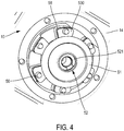
- the support 530 of the bearing 53 and the adjustment wedge 58 advantageously extend circumferentially around the hub of the pinion so that they can be screwed together to the wall by a plurality of screws 56 distributed preferably regularly around the hub 510 as on the figure 4 .
- the bearing 53 is a ball bearing, and the other 54 is a roller bearing. These two bearings are positioned on the same side of the bevel gear (unlike a conventional solution or the bevel gear is between the two bearings). This arrangement is authorized when the dynamic situation of the shaft is sound and its critical speed is high, which is the case here because the shaft is short because of the fact that the angle gear box is located integrated in the housing, and secondly that the accessory box is placed on the housing without axial offset, that is to say, without the need to add an additional shaft transfer of movement between this housing and the Angle gear box.
- the radial shaft 20 advantageously comprises an oil distributor 25, which is a cylindrical part mounted inside the end of the shaft, this end being itself in the hub of the pinion 51.
- pinion, the distributor, and the shaft are configured to allow an oil flow between the distributor 25 and the bearing assemblies 53, 54.
- the gear assembly which comprises the bearing assemblies 53, 54 mounted around the pinion 51 and the pinion itself, can be assembled before mounting by fixing the bearings and the wedge on the inner wall of the ferrule 12.
- This arrangement is simple since, as illustrated on the figure 4 it suffices to engage the screws 56 in the inner wall of the shell 12 through the support 530 of the bearing 53 and the adjustment block 58.
- the engagement assembly 40 further comprises a cover 41 which is mounted on the ferrule 12 to close the opening 35 arranged at its periphery. It can nevertheless be removed to access the interior of the housing 31, to achieve maintenance easily.
- the cover 41 comprises an oil intake connection 410 and an oil discharge connection 411, these two connections then being connected to branches of an oil circulation circuit.
- the oil supply connection 410 further comprises a protrusion 412 extending into the interior of the housing 31 towards the conical pinion 51, allowing, by injection of pressurized oil, to penetrate oil into the housing 31 to the pinion 51 which is thus lubricated, and up to the inside of its hub 510, in the oil distributor 25, which by the centrifugal effect then distributes the oil in the bearing assemblies 53, 54 to ensure lubrication.
- the housing 31 thus constitutes a housing for lubricating the bevel gear contained in the angular gearbox.
- the housing is positioned so that the angular gearbox 30 is at the base of the engine shaft of the turbomachine, below it ("at 6 o'clock").
- the opening 35 of the housing and the cover 41 is below the bevel gear between the radial shaft 20 and the accessory box, so that the oil used to lubricate the assembly of gear 50 may fall by gravity to the base of housing 31 and flow out of the housing through the oil discharge connection 411 of the cover.
- a casing 10 is made by casting, comprising an angular gear box 30 integrally formed in the shell of the casing.
- a step 1200 is brought, through the opening 35 of the housing made at the periphery of the shell (in the outer wall 32) a set gear 50 of a radial shaft with an accessory box (not shown in the figure).
- a set gear 50 of a radial shaft with an accessory box (not shown in the figure).
- 1310 is brought into a groove 520 of the hub 510 of the pinion provided for this purpose, a ring 521 for axial stop of the radial shaft in the hub 510.
- the opening 35 is then closed by means of the lid 41 during a step 1400.
- the assembly of an accessory box to this drive assembly can be carried out later by positioning a gearbox gear case in the housing 31, in gear connection with the bevel gear, and fixing the gearbox. accessories to the link arm 33 of the angular gearbox.
- the proposed solution makes it possible to integrate a gearbox in an intermediate casing, easily mounting a radial shaft and a set of gears through an opening in the housing. This facility saves time in assembly or disassembly during maintenance, and therefore a gain in terms of manufacturing cost and maintenance.
- this compact assembly allows to remove additional parts (such as the structure of the angular gearbox which was previously an additional piece reported on the housing) and thus lighten the turbomachine.
Landscapes
- Engineering & Computer Science (AREA)
- Mechanical Engineering (AREA)
- General Engineering & Computer Science (AREA)
- Chemical & Material Sciences (AREA)
- Combustion & Propulsion (AREA)
- General Details Of Gearings (AREA)
- Gear Transmission (AREA)
- Structures Of Non-Positive Displacement Pumps (AREA)
- Turbine Rotor Nozzle Sealing (AREA)
Description
- L'invention concerne un carter intermédiaire de turbomachine et un ensemble d'entrainement de machines auxiliaires de turbomachine comprenant un tel carter.
- Un exemple de turbomachine est représenté schématiquement en
figure 1 . - Une turbomachine 1 comporte typiquement une soufflante 2 d'admission d'air, une première section de compression de l'air 3 admis dans le moteur, dite section basse pression, et une seconde section de compression 4 dite section haute pression. L'air y est comprimé avant d'être admis dans une chambre de combustion 5 et mélangé avec du carburant pour y être brulé.
- Les gaz de combustion chauds issus de cette combustion sont ensuite détendus dans différents étages de turbine : un étage de turbine haute pression 6 se trouvant immédiatement en aval de la chambre de combustion, et un étage de turbine basse pression 7 détendant à nouveau les gaz en aval.
- Un arbre moteur 8 est entrainé par les deux étages de turbine et entraine en rotation les étages à basse et haute pressions de compresseurs.
- La turbomachine comprend en outre une pluralité de machines accessoires regroupées au sein d'un boitier d'accessoires (appelé en anglais Accessories Gearbox ou encore sous l'acronyme AGB), ces machines étant des équipements du type pompes, circuits de lubrification, démarreur, etc., qui, bien que ne servant pas à la propulsion sont nécessaires au fonctionnement de la turbomachine.
- Un tel boitier comprend un train d'engrenages qui est entrainé en rotation en prélevant de la puissance à l'arbre moteur au niveau du carter intermédiaire, c'est-à-dire le carter s'étendant autour de l'arbre moteur au niveau de l'intervalle entre le compresseur basse pression et le compresseur haute pression.
- Pour ce faire, un arbre radial est contenu dans le carter intermédiaire 10, qui est engrené par l'arbre moteur au moyen d'un engrenage conique intermédiaire (Intermediate GearBox ou IGB), et qui lui-même engrène le boitier d'accessoires via un engrenage conique contenu dans un boitier de renvoi d'angle (ou en anglais TGB pour Transfert GearBox) monté sur le carter intermédiaire.
- Lorsqu'une maintenance doit avoir lieu sur l'arbre radial, il est nécessaire de retirer le boitier de renvoi d'angle, voire de retirer également tout le support de machines accessoires, ce qui représente des durées et donc des coûts de maintenance importants.
- De plus, dans certaines turbomachines, le boitier d'accessoires peut être déporté axialement de manière assez lointaine par rapport au boitier de renvoi d'angle, ce qui implique de monter un arbre supplémentaire entre ces deux éléments.
- Or, dans le cadre d'efforts pour réduire le bruit causé par une turbomachine, des développements sont menés pour augmenter les diamètres des turbomachines tout en essayant de réduire leur longueur axiale. Il est donc nécessaire de limiter l'éloignement du boitier d'accessoires par rapport au boitier de renvoi d'angle.
- Enfin, il est nécessaire de réduire la masse des turbomachines pour limiter leur consommation de carburant et ainsi réduire les coûts de vol.
- Un but de l'invention est de remédier aux problèmes cités ci-avant.
- En particulier, l'invention a pour but de proposer un ensemble d'entrainement d'un boitier d'accessoires qui permette d'accéder à l'arbre radial sans avoir à démonter le boitier de renvoi d'angle ou le boitier d'accessoires.
- Un autre but de l'invention est de réduire la masse et l'encombrement axial d'une turbomachine.
- A cet égard, l'invention a pour objet un carter intermédiaire de turbomachine, comprenant :
- un moyeu interne, adapté pour recevoir un arbre de compresseur de turbomachine,
- une virole externe, et
- une pluralité de bras radiaux reliant le moyeu et la virole, l'un des bras comprenant un logement interne d'arbre radial d'entrainement de machines auxiliaires,
- Avantageusement, mais facultativement, le carter intermédiaire selon l'invention peut en outre comprendre au moins l'une des caractéristiques suivantes :
- le boitier de renvoi d'angle comprend en outre un bras de liaison avec un boitier d'accessoires, ledit bras étant creux pour recevoir un train d'engrenage du boitier d'accessoires, et le logement d'engrenage comprenant en outre une ouverture de communication avec ledit bras,
- l'ouverture du logement est disposée en regard du bras radial comprenant un logement interne d'arbre radial.
- L'invention a également pour objet un ensemble d'entrainement d'un boitier d'accessoires de turbomachine, comprenant un carter intermédiaire, un arbre radial s'étendant dans un bras radial du carter, un ensemble d'engrenage de l'arbre radial à un boitier d'accessoires, monté à une extrémité de l'arbre radial, et un boitier de renvoi d'angle de l'arbre radial, le carter étant conforme à la présentation qui précède, le boitier de renvoi d'angle étant formé intégralement dans ledit carter.
- Avantageusement, mais facultativement, l'ensemble d'entrainement selon l'invention peut en outre comprendre au moins l'une des caractéristiques suivantes : l'ensemble comprenant en outre un couvercle couvrant l'ouverture du logement du carter à la périphérie de la virole, ledit couvercle comprenant une connexion d'admission d'huile et une connexion d'évacuation d'huile.
- l'ensemble d'engrenage comporte un pignon conique comprenant un moyeu adapté pour recevoir l'extrémité de l'arbre radial, et l'ensemble d'engrenage comprend un dispositif d'arrêt axial de l'arbre radial dans le moyeu du pignon.
- le moyeu du pignon conique comprend une rainure circonférentielle interne, et le dispositif d'arrêt axial comprend une bague disposée dans la rainure du moyeu du pignon conique et faisant saillie par rapport à la surface interne du moyeu du pignon conique pour former une butée axiale de l'arbre radial.
- l'ensemble d'engrenage comprend en outre deux paliers s'étendant autour du moyeu du pignon, et l'ensemble d'entraînement comprend en outre un distributeur d'alimentation en huile monté dans l'arbre radial, en communication de fluide avec les paliers.
- L'invention concerne également une turbomachine comprenant un arbre moteur, un boitier d'accessoires, et un ensemble d'entrainement du boitier d'accessoires conforme à la description qui précède.
- L'invention concerne enfin un procédé de montage d'un tel ensemble d'entrainement de boitier d'accessoires, comprenant les étapes consistant à :
- amener un ensemble d'engrenage dans un boitier de renvoi d'angle de carter au travers d'une ouverture dans la paroi externe de la virole du carter, et fixer ledit ensemble à une paroi du boitier de renvoi d'angle, ladite paroi séparant le boitier d'un bras axial creux du carter,
- engager un arbre radial dans ledit bras du carter au travers du moyeu d'un pignon de l'ensemble d'engrenage,
- amener un dispositif d'arrêt axial de l'arbre radial dans le moyeu du pignon, et
- fermer l'ouverture à la périphérie de la virole externe par un couvercle.
- Le carter intermédiaire selon l'invention présente de nombreux avantages. Tout d'abord, en intégrant un boitier de renvoi d'angle, il permet de réduire la masse de la turbomachine, car d'une part le nombre de pièces supplémentaires à rapporter sur le carter pour assurer le fonctionnement du boitier d'accessoires est réduit, mais d'autre part ce carter intermédiaire permet de s'affranchir de l'arbre supplémentaire reliant le boitier de renvoi d'angles au train d'engrenage du boitier d'accessoires.
- En outre, ce carter permet d'accéder facilement au bras radial dans lequel est disposé l'axe radial, notamment en passant par l'ouverture sur la paroi externe de la virole du carter.
- L'ensemble d'entrainement du boitier d'accessoires comprenant un tel carter permet aussi, notamment grâce à cette ouverture, de lubrifier facilement les paliers de l'engrenage contenu dans le boitier de renvoi d'angle, et de récupérer l'huile.
- Enfin, le montage et le démontage de cet ensemble d'entrainement est aisé, ce qui permet de réduire la durée et le coût des interventions de maintenance.
- D'autres caractéristiques, buts et avantages de l'invention ressortiront de la description qui suit, qui est purement illustrative et non limitative, et qui doit être lue en regard des dessins annexés sur lesquels :
- La
figure 1 , déjà décrite, représente schématiquement une turbomachine dans laquelle peut être mise en oeuvre l'invention. - Les
figures 2a ,2b et 2c représentent un carter intermédiaire selon un mode de réalisation de l'invention, - Les
figures 3a et 3b représentent une vue en coupe partielle d'un ensemble d'engagement d'un boitier d'accessoires comprenant un tel carter intermédiaire, - La
figure 4 représente la fixation d'un ensemble d'engrenage de l'ensemble d'engagement sur une paroi du boitier de renvoi d'angle. - Les
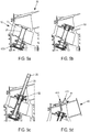
figures 5a à 5d représentent les étapes de montage d'un ensemble d'engagement, - La
figure 6 illustre sous forme de diagramme les étapes de montage de l'ensemble d'engagement. - En référence aux
figures 2a à 2c , on a représenté un carter intermédiaire 10 de turbomachine, c'est-à-dire une partie de carter qui entoure une section de l'arbre moteur de la turbomachine comprise entre un compresseur basse pression et un compresseur haute pression. A cet égard, le carter intermédiaire est une pièce annulaire s'étendant autour, et centrée sur l'axe de l'arbre de rotation de la turbomachine. - Ce carter 10 comprend un moyeu interne 11, adapté pour recevoir l'arbre moteur de la turbomachine, une virole externe 12, et une pluralité de bras radiaux 13 s'étendant entre le moyeu et la virole.
- La virole 12 comprend une paroi interne 14 reconstituant la partie supérieure de la veine du flux primaire de la turbomachine. La virole 12 comprend en outre deux parois latérales annulaires 15 et une pluralité d'entretoises.
- La paroi interne 14s'étend circonférentiellement autour de l'axe de la turbomachine, et est comprise entre les deux parois latérales annulaires 15 s'étendant radialement par rapport à l'axe de la turbomachine, avec une pluralité d'entretoises 16 s'étendant entre les parois latérales et les reliant entre elles.
- La paroi interne 14 relie entre elles les entretoises 16, qui sont réparties régulièrement sur la circonférence de la virole, et le cas échéant relie également les entretoises à l'une voire aux deux parois latérales 15.
- Les entretoises 16 sont disposées dans une direction radiale autour de l'axe de la turbomachine et se trouvent dans le prolongement des bras radiaux 13.
- Comme visible sur la
figure 2b , selon un mode de réalisation particulier, les entretoises 16 sont réparties en groupes de deux entretoises, les groupes de deux entretoises étant répartis régulièrement sur la circonférence de la virole, et en alignement avec les bras radiaux de sorte que les entretoises prolongent les bras radiaux 13 entre les parois latérales 15 de la virole. - L'ensemble du carter intermédiaire 10 comprenant le moyeu 11, les bras radiaux 13, les entretoises 16 et les parois interne 14 et latérales 15 de la virole, est moulé en fonderie d'une seule pièce.
- De préférence, au moins un bras radial 13 est creux, c'est-à-dire qu'il comprend un logement interne qui débouche avantageusement du côté interne par rapport à l'axe de la turbomachine au travers d'une ouverture pratiquée dans le moyeu 11, et du coté externe au travers d'une ouverture pratiquée dans la paroi interne 14 de la virole, de manière à pouvoir recevoir un arbre radial 20 et à relier d'une part à l'arbre moteur de la turbomachine et d'autre part à une boite de renvoi d'angle 30. Avantageusement, mais facultativement, tous les bras radiaux 13 sont creux pour pouvoir alléger la structure et permettre le passage de servitudes.
- Avantageusement, les deux entretoises 16 disposées dans le prolongement du (ou d'un) bras radial creux 13 sont davantage espacées que les autres groupes de deux entretoises, pour permettre l'intégration d'un ensemble d'engrenage comme décrit ci-après.
- Comme visible sur la
figure 3a , un arbre radial 20 s'étend dans un bras radial 13, et débouche d'un côté dans le moyeu où un engrenage conique intermédiaire ou IGB permet un premier renvoi d'angle entre l'arbre moteur et l'arbre radial, et au côté opposé dans un boitier de renvoi d'angle 30. - L'arbre radial 20 est avantageusement entouré, dans le bras radial 13, d'un fourreau d'étanchéité 21.
- En outre, le boitier de renvoi d'angle 30 est agencé dans la virole externe 12, en étant formé intégralement - c'est-à-dire moulé d'une seule pièce - avec ladite virole 12, pour former une partie intégrante du carter 10.
- Le boitier de renvoi d'angle comprend un logement 31 formé dans la virole externe, et qui est délimité axialement par les parois latérales 15, angulairement par un groupe de deux entretoises 16, et radialement d'une part par la paroi interne 14 de la virole, et d'autre part par une paroi 32 externe s'étendant à la périphérie de la virole, entre les deux entretoises 16. Alternativement, la virole 12 comprend une paroi externe s'étendant sur toute la circonférence de la virole.
- Ce logement est le siège d'un engrenage conique entre l'arbre radial 20 et un train d'engrenage (non représenté) d'un boitier d'accessoires. A cet égard, et comme visible sur la
figure 2c , le boitier de renvoi d'angle 30 comporte en outre un bras de liaison 33 avec un boitier d'accessoires, qui est creux et s'étend selon un axe non parallèle à la direction du bras radial dans lequel s'étend l'arbre radial. - Le logement 31 comprend une ouverture 34, aménagée dans une des parois latérales de la virole, pour communiquer avec le bras de liaison 33.
- En outre, le logement 31 comprend une deuxième ouverture 35, aménagée à la périphérie de la virole, dans la paroi externe 32 de celle-ci. L'ouverture 35 est disposée en regard du bras radial 13 creux dans lequel est disposé l'arbre radial 20 afin de faire passer l'arbre radial 20 dans cette ouverture pour le positionner dans le bras 13.Comme décrit ci-après, cette ouverture permet aussi l'alimentation et la récupération de l'huile de lubrification de l'engrenage conique contenu dans le boitier de renvoi d'angle.
- On va maintenant décrire, en référence aux
figures 3a et 3b , un ensemble d'entrainement 40 d'un boitier d'accessoires, qui comprend le carter 10 précédemment décrit, un arbre radial 20 disposé dans un bras radial 13 dudit carter, ainsi qu'un ensemble d'engrenage 50, pour l'engrenage de l'arbre radial 20 à un train d'engrenage d'un boitier d'accessoires. - L'ensemble d'engrenage 50 est monté sur l'extrémité externe de l'arbre radial 20 et comprend notamment un pignon conique 51, comprenant un moyeu 510 recevant l'extrémité de l'arbre radial. Le moyeu 510 du pignon et l'arbre radial sont solidaires en rotation pour assurer la transmission du mouvement de l'arbre au pignon conique 51.
- L'ensemble d'engrenage 51 comprend en outre un dispositif d'arrêt axial 52 de l'arbre radial dans le moyeu 510 du pignon.
- Selon un mode de réalisation préféré, le dispositif d'arrêt axial 52 comprend une rainure circonférentielle 520 réalisée sur la surface interne du moyeu 510, et une bague 521, dimensionnée pour être insérée dans ladite rainure de sorte qu'une fois en position dans la rainure la bague fasse saillie circonférentiellement par rapport à la surface interne du moyeu 510. Pour ce faire, la bague 521 présente avantageusement un diamètre égal au diamètre de la rainure, et une dimension radiale supérieure à la profondeur de la rainure.
- Ainsi, une fois l'arbre radial 20 monté à l'intérieur du moyeu 510 du pignon, on peut positionner la bague dans la rainure et l'arbre vient ensuite en butée contre la bague.
- L'ensemble d'engrenage 50 comprend en outre deux paliers 53, 54 de fixation du pignon dans le logement 31, les paliers étant montés adjacents autour du moyeu 510, de sorte qu'ils soient compris entre la paroi interne 14 de la virole et le pignon 51.
- Le palier le plus externe 53 comprend un support 530 qui est monté à la paroi interne du logement par boulonnage ou vissage, ce qui permet de maintenir également le deuxième palier 54 entre la paroi et ce premier palier 53.
- L'ensemble d'engrenage comprend en outre une entretoise 57 disposée entre les paliers 53, 54, et une cale de réglage 58 s'étendant entre la paroi interne du logement et le palier le plus interne 54, ces éléments permettant de caler axialement les paliers pour assurer une bonne transmission des efforts du pignon 51 au carter 10.
- Le fait d'avoir les deux paliers compris entre la cale de réglage 58 et le pignon 51 rend possible le montage et le démontage de l'ensemble d'engrenage du reste du carter 10 sans recourir à un élément de carter supplémentaire qui contient cet ensemble, ce qui représente un gain en terme de masse et de facilité de montage pour la fabrication et la maintenance, et donc une diminution des coûts d'utilisation et de fabrication de l'ensemble d'entrainement.
- Le support 530 du palier 53 et la cale de réglage 58 s'étendent avantageusement circonférentiellement autour du moyeu du pignon pour pouvoir être vissés ensemble à la paroi par une pluralité de vis 56 réparties de préférence régulièrement autour du moyeu 510 comme sur la
figure 4 . - Le palier 53 est un palier à billes, et l'autre 54 est un palier à rouleaux. Ces deux roulements sont positionnés du même coté du pignon conique (contrairement à une solution conventionnelle ou le pignon conique est entre les deux paliers). Cette disposition est autorisée lorsque la situation dynamique de l'arbre est saine et que sa vitesse critique est élevée, ce qui est le cas ici car l'arbre est court du fait d'une part que le boitier de renvoi d'angle se trouve intégré au carter, et d'autre part que le boitier d'accessoires est placé sur le carter sans déport axial, c'est-à-dire, sans la nécessité d'ajouter un arbre supplémentaire de transfert de mouvement entre ce boitier et le boitier de renvoi d'angle.
- En dévissant les vis 56 par l'extérieur (en passant par l'ouverture 35), il est possible de retirer l'ensemble d'engrenage 50 avec ses paliers et ses supports paliers en une seule opération, sans pour cela avoir à le démonter.
- L'arbre radial 20 comprend avantageusement un distributeur d'huile 25, qui est une pièce cylindrique montée à l'intérieur de l'extrémité de l'arbre, cette extrémité se trouvant elle-même dans le moyeu du pignon 51. De plus le pignon, le distributeur, et l'arbre sont configurés pour autoriser une circulation d'huile entre le distributeur 25 et les ensembles de paliers 53, 54.
- Ainsi l'ensemble d'engrenage, qui comprend les ensembles de paliers 53, 54 montés autour du pignon 51 et le pignon lui-même, peut être assemblé avant son montage par fixation des paliers et de la cale sur la paroi interne de la virole 12. Ce montage est simple puisque, comme illustré sur la
figure 4 , il suffit d'engager les vis 56 dans la paroi interne de la virole 12 au travers du support 530 du palier 53 et de la cale de réglage 58. - Comme visible sur les
figures 3a et 3b , l'ensemble d'engagement 40 comprend en outre un couvercle 41 qui est monté sur la virole 12 pour fermer l'ouverture 35 aménagée à sa périphérie. Il peut néanmoins être retiré pour pouvoir accéder à l'intérieur du logement 31, afin de réaliser une maintenance facilement. - Le couvercle 41 comprend une connexion d'admission d'huile 410 et une connexion d'évacuation d'huile 411, ces deux connexions étant ensuite raccordées à des branches d'un circuit de circulation d'huile.
- La connexion d'alimentation d'huile 410 comprend en outre une protubérance 412 s'étendant dans l'intérieur du logement 31 vers le pignon conique 51, permettant, par injection d'huile sous pression, de faire pénétrer de l'huile dans le logement 31 jusqu'au pignon 51 qui est ainsi lubrifié, et jusqu'à l'intérieur de son moyeu 510, dans le distributeur d'huile 25, qui par l'effet centrifuge répartit ensuite l'huile dans les ensembles de paliers 53, 54 pour assurer leur lubrification.
- Le logement 31 constitue ainsi une enceinte de lubrification de l'engrenage conique contenu dans le boitier de renvoi d'angle.
- En outre, comme illustré sur la
figure 2a , lorsque l'ensemble d'entrainement 40 est monté dans une turbomachine par exemple conforme à lafigure 1 , le carter est positionné de sorte que le boitier de renvoi d'angle 30 se trouve à l'aplomb de l'arbre moteur de la turbomachine, en dessous de celui-ci (« à 6 heures »). Ainsi, l'ouverture 35 du logement et le couvercle 41 se trouve en-dessous de l'engrenage conique entre l'arbre radial 20 et le boitier d'accessoires, de sorte que l'huile servant à la lubrification de l'ensemble d'engrenage 50 peut retomber par gravité à la base du logement 31 et s'écouler hors du logement par la connexion d'évacuation d'huile 411 du couvercle. - On va maintenant décrire, en référence aux
figures 5a à 5d et à lafigure 6 , un procédé de montage 1000 d'un ensemble d'entrainement 40. - Au cours d'une première étape 1100, on réalise par fonderie un carter 10 comprenant un boitier de renvoi d'angle 30 formé intégralement dans la virole du carter.
- Une fois le carter réalisé, on fixe à l'intérieur de son moyeu central 11 un engrenage conique intermédiaire IGB, comme représenté en
figure 5a , cet engrenage étant adapté pour engrener avec un engrenage complémentaire d'un arbre moteur de turbomachine, non représenté sur la figure. - Au cours d'une étape 1200, on amène, au travers de l'ouverture 35 du carter pratiquée à la périphérie de la virole (dans la paroi externe 32) un ensemble d'engrenage 50 d'un arbre radial avec un boitier d'accessoires (non représenté sur la figure). On fixe, comme illustré sur la
figure 5b , au moyen d'une pluralité de vis 56, cet ensemble sur la paroi interne 14 de la virole 12, à l'extrémité du bras radial 13. - En référence à la
figure 5c , on amène ensuite 1300 un arbre radial dans le bras radial en le faisant passer au travers de l'ouverture 35, et dans le moyeu 510 du pignon conique de l'ensemble d'engrenage. Cet arbre radial est engagé, à son extrémité interne, à l'engrenage conique intermédiaire IGB, et à son extrémité externe au moyeu 510 du pignon 51. - Avantageusement, on amène 1310 dans une rainure 520 du moyeu 510 du pignon prévue à cet effet, une bague 521 d'arrêt axial de l'arbre radial dans le moyeu 510.
- Enfin, en référence à la
figure 5d , on ferme ensuite l'ouverture 35 au moyen du couvercle 41 au cours d'une étape 1400. - L'assemblage d'un boitier d'accessoires à cet ensemble d'entrainement peut être réalisé ultérieurement en positionnant un train d'engrenage du boitier dans le logement 31, en liaison d'engrenage avec le pignon conique, et en fixant le boitier d'accessoires au bras de liaison 33 du boitier de renvoi d'angle.
- La solution proposée permet d'intégrer un boitier de renvoi d'angle dans un carter intermédiaire, en montant facilement un arbre radial et un ensemble d'engrenages au travers d'une ouverture pratiquée dans le boitier. Cette facilité permet un gain de temps dans le montage ou le démontage au cours d'une maintenance, et donc un gain en termes de coût de fabrication et d'entretien.
- En outre, ce montage compact permet de supprimer des pièces supplémentaires (comme par exemple la structure du boitier de renvoi d'angle qui était préalablement une pièce supplémentaire rapportée sur le carter) et donc d'alléger la turbomachine.
Claims (10)
- Carter intermédiaire (10) de turbomachine, comprenant :- un moyeu interne (11), adapté pour recevoir un arbre de compresseur de turbomachine,- une virole externe (12), et- une pluralité de bras radiaux (13) reliant le moyeu et la virole, l'un des bras comprenant un logement interne d'arbre radial (20) d'entrainement de machines auxiliaires, le carter comprenant en outre un boitier de renvoi d'angle (30) de l'arbre radial (20) agencé dans la virole externe (12), ledit boitier étant formé intégralement avec la virole externe (12), caractérisé en ce que le boitier de renvoi d'angle (30) comprend un logement d'engrenage (31) entre un arbre radial et un boitier d'accessoires, ledit logement (31) comprenant une ouverture (35) débouchant à la périphérie de la virole externe (12).
- Carter intermédiaire (10) selon la revendication 1, dans lequel le boitier de renvoi d'angle (30) comprend en outre un bras de liaison (33) avec un boitier d'accessoires, ledit bras étant creux pour recevoir un train d'engrenage du boitier d'accessoires, et le logement d'engrenage (31) comprenant en outre une ouverture (34) de communication avec ledit bras.
- Carter intermédiaire selon l'une des revendications 1 ou 2, dans lequel l'ouverture (35) du logement (31) est disposée en regard du bras radial (13) comprenant un logement interne d'arbre radial (20).
- Ensemble d'entraînement (40) d'un boitier d'accessoires de turbomachine, comprenant un carter intermédiaire (10), un arbre radial (20) s'étendant dans un bras radial (13) du carter, un ensemble d'engrenage (50) de l'arbre radial à un boitier d'accessoires, monté à une extrémité de l'arbre radial, et un boitier de renvoi d'angle (30) de l'arbre radial,
caractérisé en ce que le carter intermédiaire (10) est un carter selon l'une des revendications précédentes, le boitier de renvoi d'angle (30) étant formé intégralement dans ledit carter. - Ensemble d'entrainement (40) selon la revendication précédente, comprenant en outre un couvercle (41) couvrant l'ouverture (35) du logement à la périphérie de la virole (12), ledit couvercle (41) comprenant une connexion d'admission d'huile (410) et une connexion d'évacuation d'huile (411).
- Ensemble d'entrainement (40) selon l'une des revendications 4 ou 5, dans lequel l'ensemble d'engrenage (50) comporte un pignon conique (51) comprenant un moyeu (510) adapté pour recevoir l'extrémité de l'arbre radial (20), et l'ensemble d'engrenage comprend un dispositif d'arrêt axial (52) de l'arbre radial dans le moyeu du pignon.
- Ensemble d'entraînement (40) selon la revendication précédente, dans lequel le moyeu du pignon conique (510) comprend une rainure circonférentielle (520) interne, et le dispositif d'arrêt axial (52) comprend une bague (521) disposée dans la rainure du moyeu du pignon conique et faisant saillie par rapport à la surface interne du moyeu du pignon conique pour former une butée axiale de l'arbre radial.
- Ensemble d'entraînement (40) selon l'une des revendications 6 ou 7, dans lequel l'ensemble d'engrenage (50) comprend en outre deux paliers (53, 54) s'étendant autour du moyeu (510) du pignon conique, et l'ensemble d'entraînement (40) comprend en outre un distributeur d'alimentation (25) en huile monté dans l'arbre radial (20), en communication de fluide avec les paliers (53, 54).
- Turbomachine (1), comprenant un arbre moteur, un boitier d'accessoires (AGB), et un ensemble d'entrainement (40) du boitier d'accessoires selon l'une des revendications 4 à 8.
- Procédé de montage d'un ensemble d'entrainement (40) de boitier d'accessoires selon l'une des revendications 4 à 8, comprenant les étapes consistant à :- amener (1200) un ensemble d'engrenage (50) dans un boitier de renvoi d'angle de carter (10) au travers d'une ouverture dans la paroi externe de la virole du carter, et fixer ledit ensemble à une paroi (14) du boitier de renvoi d'angle, ladite paroi séparant le boitier d'un bras axial (13) creux du carter (10),- engager (1300) un arbre radial (20) dans ledit bras du carter (13) au travers du moyeu (510) d'un pignon (51) de l'ensemble d'engrenage (50),- amener (1310) un dispositif d'arrêt axial (52) de l'arbre radial dans le moyeu du pignon, et- fermer (1400) l'ouverture (35) à la périphérie de la virole externe (12) par un couvercle (41).
Applications Claiming Priority (2)
| Application Number | Priority Date | Filing Date | Title |
|---|---|---|---|
| FR1355913A FR3007458B1 (fr) | 2013-06-21 | 2013-06-21 | Carter intermediaire ameliore de turbomachine et ensemble d'entrainement de boitier d'accessoire |
| PCT/FR2014/051514 WO2014202905A1 (fr) | 2013-06-21 | 2014-06-18 | Carter intermédiaire amélioré de turbomachine et ensemble d'entrainement de boitier d'accessoire |
Publications (2)
| Publication Number | Publication Date |
|---|---|
| EP3011142A1 EP3011142A1 (fr) | 2016-04-27 |
| EP3011142B1 true EP3011142B1 (fr) | 2017-06-14 |
Family
ID=49111428
Family Applications (1)
| Application Number | Title | Priority Date | Filing Date |
|---|---|---|---|
| EP14738879.7A Active EP3011142B1 (fr) | 2013-06-21 | 2014-06-18 | Carter intermédiaire amélioré de turbomachine et ensemble d'entrainement de boitier d'accessoire |
Country Status (9)
| Country | Link |
|---|---|
| US (1) | US9689314B2 (fr) |
| EP (1) | EP3011142B1 (fr) |
| JP (1) | JP6069539B2 (fr) |
| CN (1) | CN105392967B (fr) |
| BR (1) | BR112015031685B1 (fr) |
| CA (1) | CA2915726C (fr) |
| FR (1) | FR3007458B1 (fr) |
| RU (1) | RU2665374C2 (fr) |
| WO (1) | WO2014202905A1 (fr) |
Families Citing this family (26)
| Publication number | Priority date | Publication date | Assignee | Title |
|---|---|---|---|---|
| FR3046202B1 (fr) | 2015-12-24 | 2017-12-29 | Snecma | Turboreacteur avec un moyen de reprise de poussee sur le carter inter-compresseurs |
| FR3046201B1 (fr) | 2015-12-24 | 2018-01-19 | Safran Aircraft Engines | Turboreacteur avec un moyen de reprise de poussee sur le carter inter-compresseurs |
| US10072582B2 (en) * | 2016-04-28 | 2018-09-11 | General Electric Company | Integral offset oil tank for inline accessory gearbox |
| FR3053077B1 (fr) * | 2016-06-22 | 2019-09-20 | Safran Aircraft Engines | Boitier de relais d'accessoires d'une turbomachine |
| US10260423B2 (en) | 2017-04-18 | 2019-04-16 | United Technologies Corporation | Towershaft support |
| FR3070419B1 (fr) * | 2017-08-25 | 2019-08-23 | Safran Aircraft Engines | Turboreacteur a double corps ayant un palier de butee d'arbre basse pression positionne dans le carter d'echappement |
| GB201804962D0 (en) * | 2018-03-28 | 2018-05-09 | Rolls Royce Plc | A geared turbofan engine mount arrangement |
| GB201811219D0 (en) | 2018-07-09 | 2018-08-29 | Rolls Royce Plc | Apparatus for gas turbine engines |
| RU2705499C1 (ru) * | 2018-08-06 | 2019-11-07 | Акционерное общество "Объединенная двигателестроительная корпорация" (АО "ОДК") | Промежуточный корпус газотурбинного двигателя |
| US10781705B2 (en) | 2018-11-27 | 2020-09-22 | Pratt & Whitney Canada Corp. | Inter-compressor flow divider profiling |
| US11719164B2 (en) | 2018-12-06 | 2023-08-08 | Raytheon Technologies Corporation | Conformal accessory gearbox for low bypass gas turbine engine |
| FR3091551B1 (fr) * | 2019-01-04 | 2021-02-12 | Safran Trans Systems | Déflecteur pour le carénage d’un pignon de turbomachine, boitier d’engrenages et turbomachine associés |
| FR3092888B1 (fr) * | 2019-02-14 | 2021-01-22 | Safran Trans Systems | Lubrification d’un porte-satellites pour un reducteur mecanique de turbomachine, en particulier d’aeronef |
| US11021970B2 (en) | 2019-02-20 | 2021-06-01 | General Electric Company | Turbomachine with alternatingly spaced rotor blades |
| US11085515B2 (en) | 2019-02-20 | 2021-08-10 | General Electric Company | Gearbox coupling in a turbomachine |
| US11753939B2 (en) | 2019-02-20 | 2023-09-12 | General Electric Company | Turbomachine with alternatingly spaced rotor blades |
| US11073088B2 (en) | 2019-02-20 | 2021-07-27 | General Electric Company | Gearbox mounting in a turbomachine |
| US11156097B2 (en) | 2019-02-20 | 2021-10-26 | General Electric Company | Turbomachine having an airflow management assembly |
| US11028780B2 (en) * | 2019-03-15 | 2021-06-08 | Hamilton Sundstrand Corporation | Hydraulic unit gear shrouds |
| US11274605B2 (en) * | 2019-08-30 | 2022-03-15 | Rolls-Royce Corporation | System and method for shimming a bevel gear in an IGB on a gas turbine without removal of the bevel gear |
| CN111852578B (zh) * | 2020-07-24 | 2023-02-21 | 中国科学院工程热物理研究所 | 一种主承力机匣功率输出伞齿轮轴承座结构 |
| US11572838B2 (en) | 2020-09-29 | 2023-02-07 | General Electric Company | Accessory gearbox for a turbine engine |
| FR3117530B1 (fr) * | 2020-12-15 | 2024-01-05 | Safran Aircraft Engines | Ensemble pour turbomachine d’aéronef comprenant un support d’équipements |
| US12215629B2 (en) | 2023-02-06 | 2025-02-04 | General Electric Company | Turbine engine including transfer gearbox and accessory gearbox |
| US12372030B2 (en) | 2023-12-15 | 2025-07-29 | General Electric Company | Turbine engine having a fire box |
| DE102024103191A1 (de) * | 2024-02-05 | 2025-08-07 | MTU Aero Engines AG | Gasturbinenstrukturbauteil |
Family Cites Families (17)
| Publication number | Priority date | Publication date | Assignee | Title |
|---|---|---|---|---|
| US2978869A (en) * | 1956-11-01 | 1961-04-11 | Bristol Siddeley Engines Ltd | Engine accessory mounting arrangements |
| JPS497804B1 (fr) * | 1969-12-13 | 1974-02-22 | ||
| FR2152362B1 (fr) * | 1971-09-07 | 1974-05-10 | Snecma | |
| US4525995A (en) * | 1983-04-04 | 1985-07-02 | Williams International Corporation | Oil scavening system for gas turbine engine |
| US6058791A (en) * | 1998-03-19 | 2000-05-09 | Alliedsignal, Inc. | Accessory mechanical drive for a gas turbine engine |
| FR2824362B1 (fr) * | 2001-05-03 | 2003-09-05 | Snecma Moteurs | Agencement de montage de deux lignes d'arbre coaxiales |
| JP2007500298A (ja) * | 2003-07-29 | 2007-01-11 | プラット アンド ホイットニー カナダ コーポレイション | ターボファンケースと製造方法 |
| US20050183540A1 (en) * | 2004-02-25 | 2005-08-25 | Miller Guy W. | Apparatus for driving an accessory gearbox in a gas turbine engine |
| US7500365B2 (en) * | 2005-05-05 | 2009-03-10 | United Technologies Corporation | Accessory gearbox |
| FR2907167B1 (fr) * | 2006-10-13 | 2011-11-18 | Snecma | Arbre d'entrainement de boitier a engrenages de machines auxiliaires d'un turboreacteur; machine auxiliaire supplementaire modulaire |
| FR2921973B1 (fr) * | 2007-10-04 | 2011-04-29 | Snecma | Carter intermediaire de turboreacteur et turboreacteur |
| US8333554B2 (en) * | 2007-11-14 | 2012-12-18 | United Technologies Corporation | Split gearbox and nacelle arrangement |
| US8192143B2 (en) | 2008-05-21 | 2012-06-05 | United Technologies Corporation | Gearbox assembly |
| US9816441B2 (en) * | 2009-03-30 | 2017-11-14 | United Technologies Corporation | Gas turbine engine with stacked accessory components |
| FR2971816B1 (fr) * | 2011-02-21 | 2015-11-13 | Snecma | Arbre d'entrainement de boitier a engrenages de machines auxiliaires d'un turboreacteur |
| US20120247250A1 (en) * | 2011-03-31 | 2012-10-04 | General Electric Company | Gearbox and oil spreader thereof |
| US9062611B2 (en) * | 2011-10-19 | 2015-06-23 | United Technologies Corporation | Split accessory drive system |
-
2013
- 2013-06-21 FR FR1355913A patent/FR3007458B1/fr active Active
-
2014
- 2014-06-18 WO PCT/FR2014/051514 patent/WO2014202905A1/fr not_active Ceased
- 2014-06-18 US US14/899,761 patent/US9689314B2/en active Active
- 2014-06-18 RU RU2016101721A patent/RU2665374C2/ru active
- 2014-06-18 EP EP14738879.7A patent/EP3011142B1/fr active Active
- 2014-06-18 CN CN201480038215.0A patent/CN105392967B/zh active Active
- 2014-06-18 BR BR112015031685-9A patent/BR112015031685B1/pt active IP Right Grant
- 2014-06-18 CA CA2915726A patent/CA2915726C/fr active Active
- 2014-06-18 JP JP2015563188A patent/JP6069539B2/ja active Active
Non-Patent Citations (1)
| Title |
|---|
| None * |
Also Published As
| Publication number | Publication date |
|---|---|
| EP3011142A1 (fr) | 2016-04-27 |
| CN105392967B (zh) | 2016-12-07 |
| US20160138476A1 (en) | 2016-05-19 |
| BR112015031685B1 (pt) | 2021-12-21 |
| WO2014202905A1 (fr) | 2014-12-24 |
| JP2016531226A (ja) | 2016-10-06 |
| CA2915726C (fr) | 2016-10-25 |
| RU2016101721A3 (fr) | 2018-05-07 |
| US9689314B2 (en) | 2017-06-27 |
| CN105392967A (zh) | 2016-03-09 |
| BR112015031685A2 (pt) | 2017-07-25 |
| RU2016101721A (ru) | 2017-07-26 |
| RU2665374C2 (ru) | 2018-08-29 |
| FR3007458A1 (fr) | 2014-12-26 |
| FR3007458B1 (fr) | 2017-11-10 |
| JP6069539B2 (ja) | 2017-02-01 |
| CA2915726A1 (fr) | 2014-12-24 |
Similar Documents
| Publication | Publication Date | Title |
|---|---|---|
| CA2915726C (fr) | Carter intermediaire ameliore de turbomachine et ensemble d'entrainement de boitier d'accessoire | |
| CA2951196C (fr) | Turbomachine comprenant un systeme d'entrainement d'un equipement tel qu'un boitier d'accessoires | |
| CA2869275C (fr) | Systeme de transmission de puissance pour une turbomachine | |
| EP3137741B1 (fr) | Turbomachine d'aéronef a prélèvement de puissance mécanique amélioré | |
| EP3071792B1 (fr) | Moteur modulaire | |
| EP3137740B1 (fr) | Assemblage pour turbomachine d'aeronef et son procede de montage | |
| CA2947121C (fr) | Ensemble modulaire pour une turbomachine | |
| FR2987416A1 (fr) | Dispositif de lubrification d'un reducteur epicycloidal. | |
| CA3012406A1 (fr) | Rouet de distribution d'huile avec partitionnement axial et reducteur a train epicycloidal equipe d'un tel rouet | |
| FR2991421A1 (fr) | Reducteur a train epicycloidal avec axes de satellites montes sur roulements | |
| FR2987402A1 (fr) | Dispositif de lubrification d'un reducteur epicycloidal compatible d'un montage modulaire. | |
| FR3016936A1 (fr) | Disque de rotor a dispositif de prelevement d'air centripete, compresseur comportant ledit disque et turbomachine avec un tel compresseur | |
| FR3075866A1 (fr) | Tube de degazage pour une turbomachine d'aeronef a reducteur | |
| WO2017158298A1 (fr) | Turboréacteur ayant un groupe lubrification des paliers simplifié | |
| FR3027625A1 (fr) | Turbomachine comprenant un generateur de courant electrique permettant l'injection d'huile depuis l'interieur d'un arbre de turbine | |
| FR3075868B1 (fr) | Tube de degazage pour une turbomachine d'aeronef a reducteur | |
| EP1749977B1 (fr) | Systeme d'etancheite de la chambre de lubrification arriere d'un turboreacteur | |
| EP3011157B1 (fr) | Boitier d'accessoires de turbomachine equipe d'une pompe centrifuge | |
| EP4023909A1 (fr) | Porte-satellites pour un reducteur mecanique de turbomachine d aeronef | |
| FR3099220A1 (fr) | Réducteur de vitesse à train épicycloïdal pour une turbomachine | |
| FR3026776B1 (fr) | Dispositif de transmission de puissance pour une turbomachine d'aeronef | |
| EP3990753A1 (fr) | Support de palier de sortie de turbomachine | |
| FR3164767A1 (fr) | Reducteur mecanique a elements planetaires pourvu d’un dispositif de lubrification | |
| FR3135753A1 (fr) | Boitier de relais d’accessoires pour une turbomachine | |
| FR3135755A1 (fr) | Boitier de relais d’accessoires pour une turbomachine |
Legal Events
| Date | Code | Title | Description |
|---|---|---|---|
| PUAI | Public reference made under article 153(3) epc to a published international application that has entered the european phase |
Free format text: ORIGINAL CODE: 0009012 |
|
| 17P | Request for examination filed |
Effective date: 20160120 |
|
| AK | Designated contracting states |
Kind code of ref document: A1 Designated state(s): AL AT BE BG CH CY CZ DE DK EE ES FI FR GB GR HR HU IE IS IT LI LT LU LV MC MK MT NL NO PL PT RO RS SE SI SK SM TR |
|
| AX | Request for extension of the european patent |
Extension state: BA ME |
|
| DAX | Request for extension of the european patent (deleted) | ||
| RIC1 | Information provided on ipc code assigned before grant |
Ipc: F01D 25/24 20060101ALI20170112BHEP Ipc: F01D 25/16 20060101AFI20170112BHEP Ipc: F02C 7/32 20060101ALI20170112BHEP |
|
| GRAP | Despatch of communication of intention to grant a patent |
Free format text: ORIGINAL CODE: EPIDOSNIGR1 |
|
| INTG | Intention to grant announced |
Effective date: 20170217 |
|
| GRAS | Grant fee paid |
Free format text: ORIGINAL CODE: EPIDOSNIGR3 |
|
| GRAA | (expected) grant |
Free format text: ORIGINAL CODE: 0009210 |
|
| AK | Designated contracting states |
Kind code of ref document: B1 Designated state(s): AL AT BE BG CH CY CZ DE DK EE ES FI FR GB GR HR HU IE IS IT LI LT LU LV MC MK MT NL NO PL PT RO RS SE SI SK SM TR |
|
| REG | Reference to a national code |
Ref country code: GB Ref legal event code: FG4D Free format text: NOT ENGLISH |
|
| REG | Reference to a national code |
Ref country code: CH Ref legal event code: EP Ref country code: AT Ref legal event code: REF Ref document number: 901176 Country of ref document: AT Kind code of ref document: T Effective date: 20170615 |
|
| REG | Reference to a national code |
Ref country code: FR Ref legal event code: PLFP Year of fee payment: 4 |
|
| REG | Reference to a national code |
Ref country code: IE Ref legal event code: FG4D Free format text: LANGUAGE OF EP DOCUMENT: FRENCH |
|
| REG | Reference to a national code |
Ref country code: DE Ref legal event code: R096 Ref document number: 602014010807 Country of ref document: DE |
|
| REG | Reference to a national code |
Ref country code: SE Ref legal event code: TRGR |
|
| REG | Reference to a national code |
Ref country code: NL Ref legal event code: MP Effective date: 20170614 |
|
| REG | Reference to a national code |
Ref country code: LT Ref legal event code: MG4D |
|
| PG25 | Lapsed in a contracting state [announced via postgrant information from national office to epo] |
Ref country code: LT Free format text: LAPSE BECAUSE OF FAILURE TO SUBMIT A TRANSLATION OF THE DESCRIPTION OR TO PAY THE FEE WITHIN THE PRESCRIBED TIME-LIMIT Effective date: 20170614 Ref country code: NO Free format text: LAPSE BECAUSE OF FAILURE TO SUBMIT A TRANSLATION OF THE DESCRIPTION OR TO PAY THE FEE WITHIN THE PRESCRIBED TIME-LIMIT Effective date: 20170914 Ref country code: FI Free format text: LAPSE BECAUSE OF FAILURE TO SUBMIT A TRANSLATION OF THE DESCRIPTION OR TO PAY THE FEE WITHIN THE PRESCRIBED TIME-LIMIT Effective date: 20170614 Ref country code: HR Free format text: LAPSE BECAUSE OF FAILURE TO SUBMIT A TRANSLATION OF THE DESCRIPTION OR TO PAY THE FEE WITHIN THE PRESCRIBED TIME-LIMIT Effective date: 20170614 Ref country code: GR Free format text: LAPSE BECAUSE OF FAILURE TO SUBMIT A TRANSLATION OF THE DESCRIPTION OR TO PAY THE FEE WITHIN THE PRESCRIBED TIME-LIMIT Effective date: 20170915 |
|
| REG | Reference to a national code |
Ref country code: AT Ref legal event code: MK05 Ref document number: 901176 Country of ref document: AT Kind code of ref document: T Effective date: 20170614 |
|
| PG25 | Lapsed in a contracting state [announced via postgrant information from national office to epo] |
Ref country code: RS Free format text: LAPSE BECAUSE OF FAILURE TO SUBMIT A TRANSLATION OF THE DESCRIPTION OR TO PAY THE FEE WITHIN THE PRESCRIBED TIME-LIMIT Effective date: 20170614 Ref country code: NL Free format text: LAPSE BECAUSE OF FAILURE TO SUBMIT A TRANSLATION OF THE DESCRIPTION OR TO PAY THE FEE WITHIN THE PRESCRIBED TIME-LIMIT Effective date: 20170614 Ref country code: LV Free format text: LAPSE BECAUSE OF FAILURE TO SUBMIT A TRANSLATION OF THE DESCRIPTION OR TO PAY THE FEE WITHIN THE PRESCRIBED TIME-LIMIT Effective date: 20170614 Ref country code: BG Free format text: LAPSE BECAUSE OF FAILURE TO SUBMIT A TRANSLATION OF THE DESCRIPTION OR TO PAY THE FEE WITHIN THE PRESCRIBED TIME-LIMIT Effective date: 20170914 |
|
| PG25 | Lapsed in a contracting state [announced via postgrant information from national office to epo] |
Ref country code: RO Free format text: LAPSE BECAUSE OF FAILURE TO SUBMIT A TRANSLATION OF THE DESCRIPTION OR TO PAY THE FEE WITHIN THE PRESCRIBED TIME-LIMIT Effective date: 20170614 Ref country code: CZ Free format text: LAPSE BECAUSE OF FAILURE TO SUBMIT A TRANSLATION OF THE DESCRIPTION OR TO PAY THE FEE WITHIN THE PRESCRIBED TIME-LIMIT Effective date: 20170614 Ref country code: SK Free format text: LAPSE BECAUSE OF FAILURE TO SUBMIT A TRANSLATION OF THE DESCRIPTION OR TO PAY THE FEE WITHIN THE PRESCRIBED TIME-LIMIT Effective date: 20170614 Ref country code: AT Free format text: LAPSE BECAUSE OF FAILURE TO SUBMIT A TRANSLATION OF THE DESCRIPTION OR TO PAY THE FEE WITHIN THE PRESCRIBED TIME-LIMIT Effective date: 20170614 Ref country code: EE Free format text: LAPSE BECAUSE OF FAILURE TO SUBMIT A TRANSLATION OF THE DESCRIPTION OR TO PAY THE FEE WITHIN THE PRESCRIBED TIME-LIMIT Effective date: 20170614 |
|
| REG | Reference to a national code |
Ref country code: CH Ref legal event code: PL |
|
| PG25 | Lapsed in a contracting state [announced via postgrant information from national office to epo] |
Ref country code: PL Free format text: LAPSE BECAUSE OF FAILURE TO SUBMIT A TRANSLATION OF THE DESCRIPTION OR TO PAY THE FEE WITHIN THE PRESCRIBED TIME-LIMIT Effective date: 20170614 Ref country code: ES Free format text: LAPSE BECAUSE OF FAILURE TO SUBMIT A TRANSLATION OF THE DESCRIPTION OR TO PAY THE FEE WITHIN THE PRESCRIBED TIME-LIMIT Effective date: 20170614 Ref country code: IS Free format text: LAPSE BECAUSE OF FAILURE TO SUBMIT A TRANSLATION OF THE DESCRIPTION OR TO PAY THE FEE WITHIN THE PRESCRIBED TIME-LIMIT Effective date: 20171014 Ref country code: SM Free format text: LAPSE BECAUSE OF FAILURE TO SUBMIT A TRANSLATION OF THE DESCRIPTION OR TO PAY THE FEE WITHIN THE PRESCRIBED TIME-LIMIT Effective date: 20170614 |
|
| REG | Reference to a national code |
Ref country code: DE Ref legal event code: R097 Ref document number: 602014010807 Country of ref document: DE |
|
| REG | Reference to a national code |
Ref country code: IE Ref legal event code: MM4A |
|
| PG25 | Lapsed in a contracting state [announced via postgrant information from national office to epo] |
Ref country code: MC Free format text: LAPSE BECAUSE OF FAILURE TO SUBMIT A TRANSLATION OF THE DESCRIPTION OR TO PAY THE FEE WITHIN THE PRESCRIBED TIME-LIMIT Effective date: 20170614 |
|
| PLBE | No opposition filed within time limit |
Free format text: ORIGINAL CODE: 0009261 |
|
| STAA | Information on the status of an ep patent application or granted ep patent |
Free format text: STATUS: NO OPPOSITION FILED WITHIN TIME LIMIT |
|
| PG25 | Lapsed in a contracting state [announced via postgrant information from national office to epo] |
Ref country code: CH Free format text: LAPSE BECAUSE OF NON-PAYMENT OF DUE FEES Effective date: 20170630 Ref country code: DK Free format text: LAPSE BECAUSE OF FAILURE TO SUBMIT A TRANSLATION OF THE DESCRIPTION OR TO PAY THE FEE WITHIN THE PRESCRIBED TIME-LIMIT Effective date: 20170614 Ref country code: LU Free format text: LAPSE BECAUSE OF NON-PAYMENT OF DUE FEES Effective date: 20170618 Ref country code: IE Free format text: LAPSE BECAUSE OF NON-PAYMENT OF DUE FEES Effective date: 20170618 Ref country code: LI Free format text: LAPSE BECAUSE OF NON-PAYMENT OF DUE FEES Effective date: 20170630 |
|
| REG | Reference to a national code |
Ref country code: BE Ref legal event code: MM Effective date: 20170630 |
|
| 26N | No opposition filed |
Effective date: 20180315 |
|
| REG | Reference to a national code |
Ref country code: FR Ref legal event code: PLFP Year of fee payment: 5 |
|
| PG25 | Lapsed in a contracting state [announced via postgrant information from national office to epo] |
Ref country code: SI Free format text: LAPSE BECAUSE OF FAILURE TO SUBMIT A TRANSLATION OF THE DESCRIPTION OR TO PAY THE FEE WITHIN THE PRESCRIBED TIME-LIMIT Effective date: 20170614 Ref country code: BE Free format text: LAPSE BECAUSE OF NON-PAYMENT OF DUE FEES Effective date: 20170630 |
|
| PG25 | Lapsed in a contracting state [announced via postgrant information from national office to epo] |
Ref country code: MT Free format text: LAPSE BECAUSE OF FAILURE TO SUBMIT A TRANSLATION OF THE DESCRIPTION OR TO PAY THE FEE WITHIN THE PRESCRIBED TIME-LIMIT Effective date: 20170614 |
|
| PG25 | Lapsed in a contracting state [announced via postgrant information from national office to epo] |
Ref country code: HU Free format text: LAPSE BECAUSE OF FAILURE TO SUBMIT A TRANSLATION OF THE DESCRIPTION OR TO PAY THE FEE WITHIN THE PRESCRIBED TIME-LIMIT; INVALID AB INITIO Effective date: 20140618 |
|
| PG25 | Lapsed in a contracting state [announced via postgrant information from national office to epo] |
Ref country code: CY Free format text: LAPSE BECAUSE OF FAILURE TO SUBMIT A TRANSLATION OF THE DESCRIPTION OR TO PAY THE FEE WITHIN THE PRESCRIBED TIME-LIMIT Effective date: 20170614 |
|
| PG25 | Lapsed in a contracting state [announced via postgrant information from national office to epo] |
Ref country code: MK Free format text: LAPSE BECAUSE OF FAILURE TO SUBMIT A TRANSLATION OF THE DESCRIPTION OR TO PAY THE FEE WITHIN THE PRESCRIBED TIME-LIMIT Effective date: 20170614 |
|
| PG25 | Lapsed in a contracting state [announced via postgrant information from national office to epo] |
Ref country code: TR Free format text: LAPSE BECAUSE OF FAILURE TO SUBMIT A TRANSLATION OF THE DESCRIPTION OR TO PAY THE FEE WITHIN THE PRESCRIBED TIME-LIMIT Effective date: 20170614 |
|
| PG25 | Lapsed in a contracting state [announced via postgrant information from national office to epo] |
Ref country code: PT Free format text: LAPSE BECAUSE OF FAILURE TO SUBMIT A TRANSLATION OF THE DESCRIPTION OR TO PAY THE FEE WITHIN THE PRESCRIBED TIME-LIMIT Effective date: 20170614 |
|
| PG25 | Lapsed in a contracting state [announced via postgrant information from national office to epo] |
Ref country code: AL Free format text: LAPSE BECAUSE OF FAILURE TO SUBMIT A TRANSLATION OF THE DESCRIPTION OR TO PAY THE FEE WITHIN THE PRESCRIBED TIME-LIMIT Effective date: 20170614 |
|
| PGFP | Annual fee paid to national office [announced via postgrant information from national office to epo] |
Ref country code: DE Payment date: 20250618 Year of fee payment: 12 |
|
| PGFP | Annual fee paid to national office [announced via postgrant information from national office to epo] |
Ref country code: GB Payment date: 20250625 Year of fee payment: 12 |
|
| PGFP | Annual fee paid to national office [announced via postgrant information from national office to epo] |
Ref country code: FR Payment date: 20250623 Year of fee payment: 12 |
|
| PGFP | Annual fee paid to national office [announced via postgrant information from national office to epo] |
Ref country code: SE Payment date: 20250618 Year of fee payment: 12 |
|
| PGFP | Annual fee paid to national office [announced via postgrant information from national office to epo] |
Ref country code: IT Payment date: 20250630 Year of fee payment: 12 |