EP3010653B1 - Electroacoustic transducer - Google Patents
Electroacoustic transducer Download PDFInfo
- Publication number
- EP3010653B1 EP3010653B1 EP14727791.7A EP14727791A EP3010653B1 EP 3010653 B1 EP3010653 B1 EP 3010653B1 EP 14727791 A EP14727791 A EP 14727791A EP 3010653 B1 EP3010653 B1 EP 3010653B1
- Authority
- EP
- European Patent Office
- Prior art keywords
- electroacoustic transducer
- piezoelectric element
- housing
- acoustic transmitter
- supporting elements
- Prior art date
- Legal status (The legal status is an assumption and is not a legal conclusion. Google has not performed a legal analysis and makes no representation as to the accuracy of the status listed.)
- Active
Links
- 239000000463 material Substances 0.000 claims description 22
- 230000010355 oscillation Effects 0.000 claims description 6
- 238000004026 adhesive bonding Methods 0.000 claims description 5
- 239000000853 adhesive Substances 0.000 claims description 4
- 230000001070 adhesive effect Effects 0.000 claims description 4
- 239000006260 foam Substances 0.000 claims description 4
- 229920000642 polymer Polymers 0.000 claims description 4
- 238000003466 welding Methods 0.000 claims description 4
- 238000006073 displacement reaction Methods 0.000 claims description 3
- 239000000945 filler Substances 0.000 claims description 2
- 239000007779 soft material Substances 0.000 claims 1
- 230000000694 effects Effects 0.000 description 5
- 230000005540 biological transmission Effects 0.000 description 4
- 239000002131 composite material Substances 0.000 description 4
- 229910052751 metal Inorganic materials 0.000 description 4
- 239000002184 metal Substances 0.000 description 4
- 230000005855 radiation Effects 0.000 description 4
- 230000008602 contraction Effects 0.000 description 3
- 230000033001 locomotion Effects 0.000 description 3
- 230000035945 sensitivity Effects 0.000 description 3
- 229910001369 Brass Inorganic materials 0.000 description 2
- 229910052782 aluminium Inorganic materials 0.000 description 2
- XAGFODPZIPBFFR-UHFFFAOYSA-N aluminium Chemical compound [Al] XAGFODPZIPBFFR-UHFFFAOYSA-N 0.000 description 2
- 239000010951 brass Substances 0.000 description 2
- 239000000919 ceramic Substances 0.000 description 2
- 230000005684 electric field Effects 0.000 description 2
- 239000000835 fiber Substances 0.000 description 2
- 238000004519 manufacturing process Methods 0.000 description 2
- 239000004033 plastic Substances 0.000 description 2
- 229920003023 plastic Polymers 0.000 description 2
- 239000004593 Epoxy Substances 0.000 description 1
- 229920002323 Silicone foam Polymers 0.000 description 1
- 229910000831 Steel Inorganic materials 0.000 description 1
- 239000011149 active material Substances 0.000 description 1
- 229910010293 ceramic material Inorganic materials 0.000 description 1
- 238000005253 cladding Methods 0.000 description 1
- 238000011109 contamination Methods 0.000 description 1
- 238000001514 detection method Methods 0.000 description 1
- 239000003822 epoxy resin Substances 0.000 description 1
- 230000001771 impaired effect Effects 0.000 description 1
- 238000005304 joining Methods 0.000 description 1
- 150000002739 metals Chemical class 0.000 description 1
- 238000000034 method Methods 0.000 description 1
- 229910052574 oxide ceramic Inorganic materials 0.000 description 1
- 239000011224 oxide ceramic Substances 0.000 description 1
- TWNQGVIAIRXVLR-UHFFFAOYSA-N oxo(oxoalumanyloxy)alumane Chemical compound O=[Al]O[Al]=O TWNQGVIAIRXVLR-UHFFFAOYSA-N 0.000 description 1
- 229920000647 polyepoxide Polymers 0.000 description 1
- 239000004065 semiconductor Substances 0.000 description 1
- 239000013514 silicone foam Substances 0.000 description 1
- 239000010959 steel Substances 0.000 description 1
- 238000003860 storage Methods 0.000 description 1
- XLYOFNOQVPJJNP-UHFFFAOYSA-N water Substances O XLYOFNOQVPJJNP-UHFFFAOYSA-N 0.000 description 1
Images


Classifications
-
- B—PERFORMING OPERATIONS; TRANSPORTING
- B06—GENERATING OR TRANSMITTING MECHANICAL VIBRATIONS IN GENERAL
- B06B—METHODS OR APPARATUS FOR GENERATING OR TRANSMITTING MECHANICAL VIBRATIONS OF INFRASONIC, SONIC, OR ULTRASONIC FREQUENCY, e.g. FOR PERFORMING MECHANICAL WORK IN GENERAL
- B06B1/00—Methods or apparatus for generating mechanical vibrations of infrasonic, sonic, or ultrasonic frequency
- B06B1/02—Methods or apparatus for generating mechanical vibrations of infrasonic, sonic, or ultrasonic frequency making use of electrical energy
- B06B1/06—Methods or apparatus for generating mechanical vibrations of infrasonic, sonic, or ultrasonic frequency making use of electrical energy operating with piezoelectric effect or with electrostriction
- B06B1/0644—Methods or apparatus for generating mechanical vibrations of infrasonic, sonic, or ultrasonic frequency making use of electrical energy operating with piezoelectric effect or with electrostriction using a single piezoelectric element
- B06B1/0655—Methods or apparatus for generating mechanical vibrations of infrasonic, sonic, or ultrasonic frequency making use of electrical energy operating with piezoelectric effect or with electrostriction using a single piezoelectric element of cylindrical shape
-
- B—PERFORMING OPERATIONS; TRANSPORTING
- B06—GENERATING OR TRANSMITTING MECHANICAL VIBRATIONS IN GENERAL
- B06B—METHODS OR APPARATUS FOR GENERATING OR TRANSMITTING MECHANICAL VIBRATIONS OF INFRASONIC, SONIC, OR ULTRASONIC FREQUENCY, e.g. FOR PERFORMING MECHANICAL WORK IN GENERAL
- B06B1/00—Methods or apparatus for generating mechanical vibrations of infrasonic, sonic, or ultrasonic frequency
- B06B1/02—Methods or apparatus for generating mechanical vibrations of infrasonic, sonic, or ultrasonic frequency making use of electrical energy
- B06B1/06—Methods or apparatus for generating mechanical vibrations of infrasonic, sonic, or ultrasonic frequency making use of electrical energy operating with piezoelectric effect or with electrostriction
- B06B1/0644—Methods or apparatus for generating mechanical vibrations of infrasonic, sonic, or ultrasonic frequency making use of electrical energy operating with piezoelectric effect or with electrostriction using a single piezoelectric element
- B06B1/0662—Methods or apparatus for generating mechanical vibrations of infrasonic, sonic, or ultrasonic frequency making use of electrical energy operating with piezoelectric effect or with electrostriction using a single piezoelectric element with an electrode on the sensitive surface
- B06B1/0681—Methods or apparatus for generating mechanical vibrations of infrasonic, sonic, or ultrasonic frequency making use of electrical energy operating with piezoelectric effect or with electrostriction using a single piezoelectric element with an electrode on the sensitive surface and a damping structure
- B06B1/0685—Methods or apparatus for generating mechanical vibrations of infrasonic, sonic, or ultrasonic frequency making use of electrical energy operating with piezoelectric effect or with electrostriction using a single piezoelectric element with an electrode on the sensitive surface and a damping structure on the back only of piezoelectric elements
-
- G—PHYSICS
- G01—MEASURING; TESTING
- G01S—RADIO DIRECTION-FINDING; RADIO NAVIGATION; DETERMINING DISTANCE OR VELOCITY BY USE OF RADIO WAVES; LOCATING OR PRESENCE-DETECTING BY USE OF THE REFLECTION OR RERADIATION OF RADIO WAVES; ANALOGOUS ARRANGEMENTS USING OTHER WAVES
- G01S7/00—Details of systems according to groups G01S13/00, G01S15/00, G01S17/00
- G01S7/52—Details of systems according to groups G01S13/00, G01S15/00, G01S17/00 of systems according to group G01S15/00
- G01S7/521—Constructional features
-
- G—PHYSICS
- G10—MUSICAL INSTRUMENTS; ACOUSTICS
- G10K—SOUND-PRODUCING DEVICES; METHODS OR DEVICES FOR PROTECTING AGAINST, OR FOR DAMPING, NOISE OR OTHER ACOUSTIC WAVES IN GENERAL; ACOUSTICS NOT OTHERWISE PROVIDED FOR
- G10K11/00—Methods or devices for transmitting, conducting or directing sound in general; Methods or devices for protecting against, or for damping, noise or other acoustic waves in general
- G10K11/004—Mounting transducers, e.g. provided with mechanical moving or orienting device
-
- G—PHYSICS
- G10—MUSICAL INSTRUMENTS; ACOUSTICS
- G10K—SOUND-PRODUCING DEVICES; METHODS OR DEVICES FOR PROTECTING AGAINST, OR FOR DAMPING, NOISE OR OTHER ACOUSTIC WAVES IN GENERAL; ACOUSTICS NOT OTHERWISE PROVIDED FOR
- G10K9/00—Devices in which sound is produced by vibrating a diaphragm or analogous element, e.g. fog horns, vehicle hooters or buzzers
- G10K9/18—Details, e.g. bulbs, pumps, pistons, switches or casings
- G10K9/22—Mountings; Casings
-
- G—PHYSICS
- G01—MEASURING; TESTING
- G01S—RADIO DIRECTION-FINDING; RADIO NAVIGATION; DETERMINING DISTANCE OR VELOCITY BY USE OF RADIO WAVES; LOCATING OR PRESENCE-DETECTING BY USE OF THE REFLECTION OR RERADIATION OF RADIO WAVES; ANALOGOUS ARRANGEMENTS USING OTHER WAVES
- G01S15/00—Systems using the reflection or reradiation of acoustic waves, e.g. sonar systems
- G01S15/88—Sonar systems specially adapted for specific applications
- G01S15/93—Sonar systems specially adapted for specific applications for anti-collision purposes
- G01S15/931—Sonar systems specially adapted for specific applications for anti-collision purposes of land vehicles
- G01S2015/937—Sonar systems specially adapted for specific applications for anti-collision purposes of land vehicles sensor installation details
- G01S2015/938—Sonar systems specially adapted for specific applications for anti-collision purposes of land vehicles sensor installation details in the bumper area
Definitions
- the present invention is based on an electroacoustic transducer according to the preamble of claim 1.
- a device for generating ultrasonic waves for a vehicle in which an elongate ultrasonic transducer for generating thickness oscillations is coupled to a flat component of a vehicle, in particular a bumper.
- the ultrasonic transducer comprises a sequence of piezo disks and contacting and insulating layers, the length of the piezo disks being matched to the desired ultrasonic wave frequency in air.
- the piezo disks are made of a piezoceramic fiber composite material that includes fibers running parallel to the central axis of the respective piezo disk or parallel to the longitudinal axis.
- the arrangement of piezo disks is also arranged in a supporting device. This arrangement is in turn attached to the bumper.
- an ultrasonic sensor that has a piezoceramic element that excites a bumper to oscillate and that is provided within a piezoceramic module.
- the module can be integrated into the bumper so that it is not visible from the outside.
- ribbing is formed around the piezoceramic module so that the rigidity of the bumper can be changed in this area and the mechanical impedance jump between the bumper areas can be adjusted.
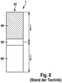
- the WO 2011/090484 A1 describes an ultrasonic transducer in the form of a thickness transducer. Based on a disk-shaped piezoceramic with electrodes, at least one front body is provided, which has a shape such that a desired emission characteristic is produced. The length of the transmission path corresponds to ⁇ /4 at a resonant frequency fR, so that the vibration from the piezoceramic disc is amplified on the radiating surface. It is also described that for some applications a ⁇ /2 oscillator is preferably used, which is more robust in particular with regard to temperature stability, susceptibility to contamination and deposits. Such a The ⁇ /2 oscillator 1 is in figure 8 shown.
- the advantage of such converters is that they can be used as sensors for detecting the surroundings of a vehicle or a robot and can be integrated into body parts of the vehicle, such as the bumper or a paneling part of the robot, so that they are invisible from the outside.
- the U.S. 5,648,942 A describes a bearing structure for an ultrasonic transducer array, this bearing structure being rod-shaped.
- the bearing structure consists of two different materials that have specific electrical and acoustic properties. In this way, the transmission of the signals generated in the converter to the corresponding processing units can be controlled.
- a ⁇ /2 thickness oscillator 1 known from the prior art, as is shown in figure 8 is shown has the disadvantage that it is very long. If the length is halved in order to transmit or receive with a ⁇ /4 thickness oscillator, the surface of the piezoceramic disc opposite the front body must be connected to a sensor housing or a holding structure. If the piezoceramic is glued to a surface or otherwise attached to a surface, this impedes the transverse contraction of the piezoceramic disc, as a result of which the sensitivity of the transducer is reduced.
- an electroacoustic transducer comprising a housing, a vibrating structure comprising at least one disc-shaped piezoelectric element having first and second surfaces and includes an acoustic transducer (also referred to as a front body).
- acoustic transducer also referred to as a front body.
- electrical connection means are provided, which are connected to electrodes of the piezoelectric element.
- the converter according to the invention works according to the known principle. When the transducer is operated as a transmitter, the piezoelectric element is excited to vibrate, which is transmitted to the front body and radiated as sound waves. If the converter is operated as a receiver, incoming sound waves are converted into electrical signals by the piezoelectric element.
- the front body connects the surface of the sound reception with the piezoelectric element and thus acts as an acoustic transmitter. The vibration generated is amplified by the resonant design of the composite component.
- the acoustic transducer has a first surface and a second surface parallel to the first surface. It is preferably rod-like and can have a cylindrical or rectangular shape, for example.
- the first surface of the acoustic transducer is bonded to the first surface of the piezoelectric element.
- the second surface of the acoustic transducer, opposite the first, is suitable for emitting or receiving sound waves.
- the distance between the second surface of the acoustic transducer and the second surface of the piezoelectric element essentially corresponds to 1 ⁇ 4 of the wavelength ( ⁇ /4) of a resonant vibration of the vibrating structure. Accordingly, the oscillating structure represents a so-called ⁇ /4 thickness oscillator, as is known from the prior art.
- the vibration occurs mainly in a direction perpendicular to the surface of the piezoelectric element (thickness vibration). Accordingly, when acoustic vibrations are received, forces are exerted on the piezoelectric element, which cause longitudinal and transverse expansion of the piezoelectric element. Impeding this transverse strain would lead to a reduction in the sensitivity of the transducer.
- the piezoelectric element is connected to the housing, for example via its second surface, by means of a bearing structure, the bearing structure being formed by transverse strains to allow the piezoelectric element.
- the oscillating structure is secured mechanically in the housing without transverse expansions or transverse contractions of the piezoelectric element being impaired by the fastening.
- the bearing structure comprises a plurality of rod-shaped supporting elements which extend between the second surface of the piezoelectric element and an inner surface of the housing.
- the support elements can have a ceramic material or a metal, for example. Materials with high rigidity (i.e. high modulus of elasticity) are preferred in order to enable the vibrator to be rigidly supported, for example an aluminum oxide ceramic or steel. However, it is also possible to use materials with a lower rigidity (e.g. aluminum or brass), as long as this is suitably taken into account when dimensioning the vibrating structure.
- the support elements prevent displacement of the oscillating structure in the thickness direction and, according to the invention, allow transverse expansion of the piezoelectric element due to their low rigidity in the transverse direction.
- the support elements are designed in the form of rods, that is to say have comparatively large longitudinal dimensions and small dimensions in the transverse direction.
- the dimensions in the transverse direction can, for example, be approximately 1/4 to 1/200 of the transverse dimension of the piezoelectric element. Due to such dimensions, a low rigidity of the support elements is achieved in the transverse direction.
- the supporting elements follow the transverse movement of the piezoelectric element with little counterforce. The effect according to the invention is thus advantageously achieved by the rod shape, that transverse expansion of the piezoelectric element is impeded as little as possible.
- the rod-shaped support elements are preferably arranged parallel to one another in their longitudinal extension and each have a cross section that is significantly smaller than the surface of the piezoelectric element.
- the supporting elements are preferably designed to be essentially identical to one another. However, support elements can also be provided which are designed differently from one another, for example by the shape and/or the cross section and/or the material of at least two support elements are designed differently.
- An embodiment of the invention is particularly preferred in which the supporting elements are encased with a filling material that is in particular flexible or elastic, or are embedded in such a filling material.
- the material can, for example, comprise a polymer or a foam, for example the two-component silicone foam Fermasil (Sonderhoff company) or an epoxy material.
- the support elements are formed in one piece with the piezoelectric element.
- the supporting elements can already be formed during the manufacture of the piezoelectric element. This saves a fastening step when assembling the electroacoustic transducer according to the invention and simplifies the structure as a whole.
- the support elements are preferably connected to the housing by means of an electrically conductive adhesive. This allows direct contacting of the piezoelectric element.
- the bearing structure is formed in that the support elements are arranged on a base element or are formed in one piece with the base element.
- the base element is attached to the housing of the electroacoustic transducer, for example by gluing. This design also simplifies the assembly of the electroacoustic converter.
- the supporting elements themselves have a piezoelectric material, in particular a piezoceramic material.
- An arrangement of such supporting elements aligned in parallel is provided, the arrangement of piezoelectrically active supporting elements forming the piezoelectric element of the electroacoustic converter provided according to the invention.
- Each individual support element acts as a separate piezo element, wherein each of the support elements is preferably rod-shaped and the support elements have mutually parallel end faces.
- the individual support elements can be embedded in a flexible material such as a foam or a polymer. A first end face of each support element is connected to the first surface of the acoustic transducer.
- each support element is connected to the housing.
- the electrical connection means can be contacted on the end faces of the support elements or alternatively can be contacted on opposite side faces of the support elements.
- a similar structure of a piezoelectric element is known from so-called composite piezoceramics, but in contrast to the present invention, with the known composite piezoceramics, the piezoelectric rods are used directly as vibrators for sound transmission or for sound reception in relation to an adjacent area (e.g. air or water). act and not serve as a support element.
- the support elements in the form of rods, ie, for example, in the form of a cylinder, cuboid, or generally prismatic. It is advantageous for the support elements to be designed conically or in the manner of a truncated cone or in the shape of a pyramid or truncated pyramid. In this case, it is advantageous to connect the smaller end face or the tip of the cone or pyramid to the piezoelectric element and to connect the larger end face, ie the base of the pyramid, truncated pyramid, cone or truncated cone, to the housing . In this way, the transverse expansion of the piezoelectric element is impeded as little as possible and a durable mechanical connection between the support elements and the housing is nevertheless created.
- the acoustic transmitter of the electroacoustic converter according to the invention can be designed in different ways.
- the first surface of the acoustic transmitter and the second surface of the acoustic transmitter are of unequal size and/or unequal shape.
- the resonant frequency of the oscillating structure can be influenced by adjusting the ratio of the surfaces and by the respective shapes of the surfaces.
- a specific radiation characteristic of the radiated sound waves can be achieved.
- the first surface of the acoustic transducer is essentially circular and the second surface of the acoustic transducer is essentially rectangular. This achieves a fan-shaped radiation pattern.
- the first and second surfaces of the acoustic transducer may both each be substantially circular in shape, with the diameter of the first surface being smaller or larger than the diameter of the second surface.
- the invention relates to an arrangement comprising an electroacoustic converter according to one of the embodiments described above and a covering element of a vehicle, in particular a bumper.
- the arrangement is characterized in that the electroacoustic transducer is attached to an inner surface of the trim member in such a manner that the electroacoustic transducer is invisible from the outside.
- the second surface of the acoustic transducer is acoustically coupled to a portion of the trim panel, wherein the trim panel has a reduced thickness in that area.
- the arrangement according to the invention can be used, for example, as an ultrasonic sensor for an environment detection system of the vehicle.
- this area should have a thickness of 0.1 to 10 mm, with a radiation frequency of 40 -100kHz.
- the housing of the electroacoustic converter is preferably attached to the inner surface of the lining element by welding or gluing or screwing.
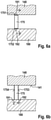
- figure 1 shows schematically how an oscillating structure designed as a ⁇ /4 thickness oscillator is attached to a housing 180 .
- a bearing 170 is created according to the invention, as is idealized in figure 1 is shown.
- the vibration in the thickness direction is restrained, but the vibration in the transverse direction is not.
- the hindrance of the oscillation in the thickness direction enables the design as a ⁇ /4 thickness oscillator with the associated advantage of the short design.
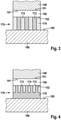
- FIG. 2 shows an arrangement of an electroacoustic transducer 100 on the inside of a bumper 200 of a vehicle.
- the bumper 200 is only partially shown.
- the electroacoustic converter 100 comprises a housing 180, an oscillating structure comprising at least one disc-shaped piezoelectric element 150 made of a piezoceramic, which has a first and a second surface 151, 152 parallel to the first.
- the oscillating structure includes an acoustic transmitter 140, which includes a rod 143 and a disk 145 in this example.
- the acoustic transducer is formed of, for example, a metal such as aluminum or brass, or a rigid plastic such as an epoxy resin.
- the rod 143 has a first Surface 141 with a diameter b 1 , which is connected to the first surface 151 of the piezoelectric element 150, for example by an adhesive. At its end remote from the piezoelectric element 150, the rod 143 has a disc 145 with a larger diameter b 2 .
- a second surface 142 ′ of the acoustic transmitter 140 or of the pane 145 is connected to an inner surface 212 of the bumper 200 , the bumper 200 having a reduced thickness D in this connection area 210 .
- the area 210 can thus vibrate and only a small proportion of structure-borne noise is transmitted to the rest of the bumper.
- the outwardly facing surface 142 of the area 210 is therefore suitable for radiating or receiving sound waves.
- the oscillating structure accordingly comprises the piezoelectric element 150, the acoustic transmitter 140 from the rod 143 and the plate 145, and the area 210 of the bumper 200 and is designed as a ⁇ /4 thickness oscillator.
- the distance d, measured from the surface 142 to the second surface 152 of the piezoelectric element 152 essentially corresponds to 1 ⁇ 4 of the wavelength ⁇ of a resonance oscillation of the oscillating structure.
- the shape of the cross section of the rod 143 can be chosen freely, for example circular, elliptical, rectangular. Also, the cross-sectional shapes of the piezoelectric element 150, the rod 143 and the plate 145 may be different from each other. Furthermore, the ratio of the diameters b 1 /b 2 can be freely selected. By choosing the dimension b 2 , both the radiation characteristics (directional characteristics of the sound emission and sound reception) and the resonant frequency of the ⁇ /4 oscillator can be adjusted. The thickness of the plate 145 affects this as well.
- the plate 145 and the rod 143 can be manufactured separately, for example, and then combined using a suitable joining method, such as gluing, welding or screwing.
- the housing 180 is pot-shaped and preferably has a high acoustic impedance, ie has a high rigidity and/or mass.
- the inventive attachment or connection of the piezoelectric element 150 to the housing 180, more precisely to the housing inner surface 185, by means of a suitable bearing structure 170 can be implemented in various ways. What they have in common is the least possible hindrance to lateral expansion. Various options for forming the bearing structure 170 are described in more detail below.
- the bearing structure 170 comprises a plurality of rod-shaped support elements 172 which are arranged parallel to one another and extend between the second surface 152 of the piezoelectric element 150 and the housing 180 or the housing inner surface 185.
- the supporting elements 172 prevent a displacement of the oscillating structure in the direction of thickness and, due to their low rigidity in the transverse direction, allow transverse expansion of the piezoelectric element 150. So that the supporting elements 172 can be arranged regularly, they are encased with a filling material 174, which in particular fills the gaps between the rods fills in Metals, ceramics and plastics can be selected as the material for the support elements 172 .
- the filler material 174 is preferably a compliant material such as a polymer or foam.
- FIG 4 shows an example of a bearing structure 170 not according to the invention.
- Rod-shaped support elements 172 which are arranged parallel to one another, are also provided here.
- the support elements 172 are arranged on a common plate 178 which serves as a base element for the support elements 172 .
- the support elements 172 can preferably be formed in one piece with the plate 178 .
- the plate 178 is preferably made of a metal or a ceramic and is attached to the housing 180 by gluing or welding, for example. It is also conceivable to form the plate 178 and/or the support elements 172 directly in one piece with the housing 180 .
- the bearing structure includes 170 several rod-shaped support elements 172, which are coated with a filling material 174.
- the support elements 172 are formed here in one piece with the piezoelectric element 150 . This results in the possibility of electrically contacting the piezoelectric element directly via the housing 180, which is metallic in this case.
- the end faces of the support elements 172 are mechanically and electrically connected to the housing 180 by means of an electrically conductive adhesive 179 . No additional electrical lines are therefore necessary.
- a piezoelectric element 150 is provided, which is constructed from a plurality of rod-shaped elements 175 arranged in parallel and comprising a piezoelectrically active material, such as a piezoceramic.
- the rod-shaped elements 175 are oriented such that they extend between the first surface 141 of the acoustic transducer 140 and the housing 180 .
- the rod-shaped elements 175 are embedded in a flexible material 174 so that the transverse expansion of the individual rod-shaped elements 175 is prevented from being hindered. Accordingly, the piezoelectric element 150 itself forms the bearing structure 170 .
- each rod-shaped element 175 has a first and a second end face 1751, 1752, respectively.
- the first faces 1751 are connected to the first surface 141 of the acoustic transducer 140 .
- the second faces 1752 are connected to the housing 180 .
- Electrical contacting 191, 192 can be made either via the end faces 1751, 1752, as in Figure 6a ) shown, or via two lateral surfaces 1753, 1754, as in Figure 6b ) shown.
- the different vibration properties of the piezoelectric element 150 are different than electrical output signal converted.
- the so-called d33 effect is used, ie the electric field and the direction of motion of the oscillation are aligned in parallel.
- the arrangement of the electrodes on the lateral surfaces 1753 and 1754 utilizes the d31 effect, ie the electric field and the direction of movement of the oscillation are aligned perpendicular to one another.
- the d33 effect or d31 effect can be larger.
- FIG 7 Another example of a bearing structure 170 not in accordance with the present invention is shown.
- This non-inventive example largely corresponds to the exemplary embodiment figure 3 .
- the support elements 176 are not rod-shaped here, but are designed in the manner of a truncated cone.
- the respective base surface 1762 of the truncated cone, ie the larger surface, is connected to the housing 180 and the respective top surface 1761 is connected to the second surface 152 of the piezoelectric element 150 .
- the transverse expansion of the piezoelectric element is impeded as little as possible and a durable mechanical connection between the support elements and the housing is nevertheless created.
Description
Die vorliegende Erfindung geht aus von einem elektroakustischen Wandler gemäß dem Oberbegriff des Anspruchs 1.The present invention is based on an electroacoustic transducer according to the preamble of claim 1.
Aus der
In der
Aus der
Die
Aus der
Die
Die Dokumente
Ein aus dem Stand der Technik bekannter λ/2-Dickenschwinger 1, wie er in
Es ist somit die Aufgabe der Erfindung einen elektroakustischen Wandler anzugeben, der die vorteilhaften Eigenschaften eines λ/4-Dickenschwinger bezüglich der Länge, also der Baugröße aufweist, und dessen Sensitivität dennoch der eines λ/2-Dickenschwinger entspricht oder dieser zumindest nahe kommt. Es soll erfindungsgemäß eine Behinderung der Querkontraktion des piezoelektrischen Elements verhindert werden.It is therefore the object of the invention to specify an electroacoustic transducer which has the advantageous properties of a λ/4 thickness oscillator in terms of length, i.e. size, and whose sensitivity nevertheless corresponds to that of a λ/2 thickness oscillator or at least comes close to it. According to the invention, an obstruction of the transverse contraction of the piezoelectric element is to be prevented.
Diese Aufgabe wird durch einen elektroakustischen Wandler mit den Merkmalen des Anspruchs 1 gelöst.This object is achieved by an electroacoustic transducer having the features of claim 1.
Es ist ein elektroakustischer Wandler vorgesehen, der ein Gehäuse, eine schwingende Struktur umfassend mindestens ein scheibenförmiges piezoelektrisches Element mit einer ersten und einer zweiten Oberfläche und einen akustischen Übertrager (auch als Vorderkörper bezeichnet) umfasst. Zur Ansteuerung des piezoelektrischen Elements sind elektrische Verbindungsmittel vorgesehen, die mit Elektroden des piezoelektrischen Elements verbunden sind. Der erfindungsgemäße Wandler funktioniert nach dem bekannten Prinzip. Wenn der Wandler als Sender betrieben wird, wird das piezoelektrische Element zu Schwingungen angeregt, die sich auf den Vorderkörper übertragen und als Schallwellen abgestrahlt werden. Wird der Wandler als Empfänger betrieben, werden eintreffende Schallwellen durch das piezoelektrische Element in elektrische Signale umgewandelt. Der Vorderkörper verbindet die Fläche des Schallempfanges mit dem piezoelektrischen Element und wirkt damit als akustischer Übertrager. Durch die resonante Auslegung des Bauteilverbundes wird die die erzeugte Schwingung verstärkt.There is provided an electroacoustic transducer comprising a housing, a vibrating structure comprising at least one disc-shaped piezoelectric element having first and second surfaces and includes an acoustic transducer (also referred to as a front body). To control the piezoelectric element, electrical connection means are provided, which are connected to electrodes of the piezoelectric element. The converter according to the invention works according to the known principle. When the transducer is operated as a transmitter, the piezoelectric element is excited to vibrate, which is transmitted to the front body and radiated as sound waves. If the converter is operated as a receiver, incoming sound waves are converted into electrical signals by the piezoelectric element. The front body connects the surface of the sound reception with the piezoelectric element and thus acts as an acoustic transmitter. The vibration generated is amplified by the resonant design of the composite component.
Der akustische Übertrager weist eine erste Oberfläche und eine zu der ersten Oberfläche parallele zweite Oberfläche auf. Er ist bevorzugt stabartig ausgebildet und kann beispielsweise eine zylindrische oder rechteckige Form aufweisen. Die erste Oberfläche des akustischen Übertragers ist mit der ersten Oberfläche des piezoelektrischen Elements verbunden. Die zweite, der ersten gegenüberliegende, Oberfläche des akustischen Übertragers ist geeignet, Schallwellen abzustrahlen oder zu empfangen. Der Abstand zwischen der zweiten Oberfläche des akustischen Übertragers und der zweiten Oberfläche des piezoelektrischen Elements entspricht im Wesentlichen ¼ der Wellenlänge (λ/4) einer Resonanzschwingung der schwingenden Struktur. Die schwingende Struktur stellt demnach einen sogenannten λ/4-Dickenschwinger dar, wie er aus dem Stand der Technik bekannt ist. Die Schwingung erfolgt hauptsächlich in einer Richtung senkrecht zur Oberfläche des piezoelektrischen Elements (Dickenschwingung). Beim Empfangen von akustischen Schwingungen werden demnach Kräfte auf das piezoelektrische Element ausgeübt, die eine Längs- und Querdehnung des piezoelektrischen Elements verursachen. Eine Behinderung dieser Querdehnung würde zu einer Verringerung der Sensitivität des Wandlers führen.The acoustic transducer has a first surface and a second surface parallel to the first surface. It is preferably rod-like and can have a cylindrical or rectangular shape, for example. The first surface of the acoustic transducer is bonded to the first surface of the piezoelectric element. The second surface of the acoustic transducer, opposite the first, is suitable for emitting or receiving sound waves. The distance between the second surface of the acoustic transducer and the second surface of the piezoelectric element essentially corresponds to ¼ of the wavelength (λ/4) of a resonant vibration of the vibrating structure. Accordingly, the oscillating structure represents a so-called λ/4 thickness oscillator, as is known from the prior art. The vibration occurs mainly in a direction perpendicular to the surface of the piezoelectric element (thickness vibration). Accordingly, when acoustic vibrations are received, forces are exerted on the piezoelectric element, which cause longitudinal and transverse expansion of the piezoelectric element. Impeding this transverse strain would lead to a reduction in the sensitivity of the transducer.
Erfindungsgemäß ist daher vorgesehen, dass das piezoelektrische Element, beispielsweise über seine zweite Oberfläche, mittels einer Lagerstruktur mit dem Gehäuse verbunden ist, wobei die Lagerstruktur ausgebildet ist, Querdehnungen des piezoelektrischen Elements zu ermöglichen. Mit anderen Worten wird eine sichere mechanische Befestigung der schwingenden Struktur in dem Gehäuse erzielt, ohne dass Querdehnungen bzw. Querkontraktionen des piezoelektrischen Elements durch die Befestigung beeinträchtigt werden.According to the invention, it is therefore provided that the piezoelectric element is connected to the housing, for example via its second surface, by means of a bearing structure, the bearing structure being formed by transverse strains to allow the piezoelectric element. In other words, the oscillating structure is secured mechanically in the housing without transverse expansions or transverse contractions of the piezoelectric element being impaired by the fastening.
Erfindungsgemäß umfasst die Lagerstruktur dazu mehrere stäbchenförmige, Abstützelemente, die sich zwischen der zweite Oberfläche des piezoelektrischen Elements und einer Innenfläche des Gehäuses erstrecken. Die Abstützelemente können beispielsweise ein Keramikmaterial oder ein Metall aufweisen. Bevorzugt sind Materialien mit hoher Steifigkeit (d.h. hohem Elastizitätsmodul), um eine steife Abstützung des Schwingers zu ermöglichen, beispielsweise eine Aluminiumoxid-Keramik oder Stahl. Es ist jedoch auch möglich, Materialien mit geringerer Steifigkeit (z. B. Aluminium oder Messing) einzusetzen, sofern dies bei der Dimensionierung der schwingenden Struktur geeignet berücksichtigt wird. Die Abstützelemente verhindern erfindungsgemäß eine Verschiebung der schwingenden Struktur in Dickenrichtung und ermöglichen erfindungsgemäß durch ihre geringe Steifigkeit in Querrichtung eine Querdehnung des piezoelektrischen Elements. Dies wird bevorzugt dadurch erreicht, in dem die Abstützelemente in Stabform ausgebildet werden, also im Vergleich große Längsabmessungen und kleine Abmessungen in Querrichtung besitzen. Die Abmessungen in Querrichtung können beispielsweise ca. 1/4 bis 1/200 der Querabmessung des piezoelektrischen Elements annehmen. Durch solche Abmessungen wird eine geringe Steifigkeit der Abstützelemente in Querrichtung erreicht. Die Abstützelemente folgen der Querbewegung des piezoelektrischen Elements mit geringer Gegenkraft. Somit wird durch die Stäbchenform in vorteilhafter Weise der erfindungsgemäße Effekt erzielt, dass eine Querdehnung des piezoelektrischen Elements möglichst wenig behindert wird.For this purpose, according to the invention, the bearing structure comprises a plurality of rod-shaped supporting elements which extend between the second surface of the piezoelectric element and an inner surface of the housing. The support elements can have a ceramic material or a metal, for example. Materials with high rigidity (i.e. high modulus of elasticity) are preferred in order to enable the vibrator to be rigidly supported, for example an aluminum oxide ceramic or steel. However, it is also possible to use materials with a lower rigidity (e.g. aluminum or brass), as long as this is suitably taken into account when dimensioning the vibrating structure. According to the invention, the support elements prevent displacement of the oscillating structure in the thickness direction and, according to the invention, allow transverse expansion of the piezoelectric element due to their low rigidity in the transverse direction. This is preferably achieved in that the support elements are designed in the form of rods, that is to say have comparatively large longitudinal dimensions and small dimensions in the transverse direction. The dimensions in the transverse direction can, for example, be approximately 1/4 to 1/200 of the transverse dimension of the piezoelectric element. Due to such dimensions, a low rigidity of the support elements is achieved in the transverse direction. The supporting elements follow the transverse movement of the piezoelectric element with little counterforce. The effect according to the invention is thus advantageously achieved by the rod shape, that transverse expansion of the piezoelectric element is impeded as little as possible.
Die stäbchenförmigen Abstützelemente sind bevorzugt in ihrer Längserstreckung parallel zueinander angeordnet und weisen jeweils einen Querschnitt auf, der wesentlich kleiner ist als die Oberfläche des piezoelektrischen Elements. Bevorzugt sind die Abstützelemente im Wesentlichen identisch zueinander ausgebildet. Es können jedoch auch Abstützelemente vorgesehen sein, die unterschiedlich zueinander ausgebildet sind, indem beispielsweise die Form und/oder der Querschnitt und/oder das Material von mindestens zwei Abstützelementen unterschiedlich ausgebildet sind.The rod-shaped support elements are preferably arranged parallel to one another in their longitudinal extension and each have a cross section that is significantly smaller than the surface of the piezoelectric element. The supporting elements are preferably designed to be essentially identical to one another. However, support elements can also be provided which are designed differently from one another, for example by the shape and/or the cross section and/or the material of at least two support elements are designed differently.
Besonders bevorzugt ist eine Ausführung der Erfindung, bei der die Abstützelemente mit einem insbesondere nachgiebigen oder elastischen, Füllmaterial ummantelt oder in ein derartiges Füllmaterial eingebettet sind. Das Material kann beispielsweise ein Polymer oder einen Schaum, beispielsweise den Zweikomponenten-Silikonschaum Fermasil (Firma Sonderhoff) oder ein Epoxy-Material umfassen. Durch das Ummanteln mit einem derartigen Füllmaterial ist es fertigungstechnisch einfacher, eine regelmäßige Anordnung der Abstützelemente zu erzielen.An embodiment of the invention is particularly preferred in which the supporting elements are encased with a filling material that is in particular flexible or elastic, or are embedded in such a filling material. The material can, for example, comprise a polymer or a foam, for example the two-component silicone foam Fermasil (Sonderhoff company) or an epoxy material. By sheathing with such a filling material, it is easier in terms of production technology to achieve a regular arrangement of the support elements.
Bevorzugt ist eine Ausbildung der Erfindung, bei der die Abstützelemente einteilig mit dem piezoelektrischen Element ausgebildet sind. Beispielsweise können die Abstützelemente bereits bei der Fertigung des piezoelektrischen Elementes ausgebildet werden. Somit wird ein Befestigungsschritt bei der Montage des erfindungsgemäßen elektroakustischen Wandlers eingespart und der Aufbau insgesamt vereinfacht. Bevorzugt sind die Abstützelemente mittels eines elektrisch leitfähigen Klebstoffs mit dem Gehäuse verbunden sind. Dies erlaubt die direkte Kontaktierung des piezoelektrischen Elements.An embodiment of the invention is preferred in which the support elements are formed in one piece with the piezoelectric element. For example, the supporting elements can already be formed during the manufacture of the piezoelectric element. This saves a fastening step when assembling the electroacoustic transducer according to the invention and simplifies the structure as a whole. The support elements are preferably connected to the housing by means of an electrically conductive adhesive. This allows direct contacting of the piezoelectric element.
In einer alternativen Ausführung der Erfindung wird die Lagerstruktur ausgebildet, indem die Abstützelemente auf einem Basiselement angeordnet werden oder einteilig mit dem Basiselement ausgebildet sind. Da Basiselement ist an dem Gehäuse des elektroakustischen Wandlers befestigt, beispielsweise durch Kleben. Auch durch diese Ausführung wird die Montage des elektroakustischen Wandlers vereinfacht.In an alternative embodiment of the invention, the bearing structure is formed in that the support elements are arranged on a base element or are formed in one piece with the base element. The base element is attached to the housing of the electroacoustic transducer, for example by gluing. This design also simplifies the assembly of the electroacoustic converter.
In einer anderen alternativen Ausführung der Erfindung ist vorgesehen, dass die Abstützelemente selbst ein piezoelektrisches Material, insbesondere ein Piezokeramikmaterial, aufweisen. Es wird eine Anordnung aus parallel ausgerichteten derartigen Abstützelementen vorgesehen, wobei die Anordnung aus piezoelektrisch aktiven Abstützelementen das erfindungsgemäß vorgesehene piezoelektrische Element des elektroakustischen Wandlers ausbildet. Jedes einzelne Abstützelement wirkt als separates Piezoelement, wobei jedes der Abstützelemente bevorzugt stäbchenförmig ausgebildet ist und die Abstützelemente zueinander parallele Stirnflächen aufweisen. Zur Ausbildung eines derartigen piezoelektrischen Elements können die einzelnen Abstützelemente in ein nachgiebiges Material, wie zum Beispiel einen Schaum oder ein Polymer eingebettet werden. Jeweils eine erste Stirnfläche jedes Abstützelementes ist mit der ersten Oberfläche des akustischen Übertragers verbunden. Die jeweilige zweite Stirnfläche jedes Abstützelements ist mit dem Gehäuse verbunden ist. Der Vorteil dieser Ausführung liegt darin, dass keine separate Lagerstruktur benötigt wird. Die die Zahl der Bauteile des elektroakustischen Wandlers wird damit weiter verringert und die Baugröße reduziert. Zur elektrischen Kontaktierung des piezoelektrischen Elements können die elektrischen Verbindungsmittel an den Stirnflächen der Abstützelemente kontaktiert sein oder alternativ an gegenüberliegenden Seitenflächen der Abstützelemente kontaktiert sein. Ein ähnlicher Aufbau eines piezoelektrischen Elements ist von sogenannten Composite-Piezokeramiken bekannt, wobei jedoch im Gegensatz zur vorliegenden Erfindung bei den bekannten Composite-Piezokeramiken die piezoelektrischen Stäbe direkt als Schwinger zur Schallaussendung oder zum Schallempfang in Bezug auf ein angrenzendes Gebiet (z.B. Luft oder Wasser) wirken und nicht als Abstützelement dienen.In another alternative embodiment of the invention, it is provided that the supporting elements themselves have a piezoelectric material, in particular a piezoceramic material. An arrangement of such supporting elements aligned in parallel is provided, the arrangement of piezoelectrically active supporting elements forming the piezoelectric element of the electroacoustic converter provided according to the invention. Each individual support element acts as a separate piezo element, wherein each of the support elements is preferably rod-shaped and the support elements have mutually parallel end faces. To form such a piezoelectric element, the individual support elements can be embedded in a flexible material such as a foam or a polymer. A first end face of each support element is connected to the first surface of the acoustic transducer. The respective second face of each support element is connected to the housing. The advantage of this design is that no separate storage structure is required. The number of components of the electroacoustic converter is thus further reduced and the overall size is reduced. For electrical contacting of the piezoelectric element, the electrical connection means can be contacted on the end faces of the support elements or alternatively can be contacted on opposite side faces of the support elements. A similar structure of a piezoelectric element is known from so-called composite piezoceramics, but in contrast to the present invention, with the known composite piezoceramics, the piezoelectric rods are used directly as vibrators for sound transmission or for sound reception in relation to an adjacent area (e.g. air or water). act and not serve as a support element.
Generell ist es möglich, die die Abstützelemente stäbchenförmig auszubilden, also beispielsweise zylinderförmig, quaderförmig, oder allgemein prismenförmig. Vorteilhaft ist es, die Abstützelemente konisch oder kegelstumpfartig oder pyramiden- oder pyramidenstumpfförmig auszubilden. In diesem Fall ist es vorteilhaft die jeweils kleinere Stirnfläche bzw. die Spitze des Konus oder der Pyramide mit dem piezoelektrischen Element zu verbinden und die größere Stirnfläche, also die Grundfläche der Pyramide, des Pyramidenstumpfs, des Konus oder der Kegelstumpfs, mit dem Gehäuse zu verbinden. Auf diese Weise wird die Querdehnung des piezoelektrischen Elements so geringfügig wie möglich behindert und trotzdem eine haltbare mechanische Verbindung der Abstützelemente zum Gehäuse geschaffen.In general, it is possible to construct the support elements in the form of rods, ie, for example, in the form of a cylinder, cuboid, or generally prismatic. It is advantageous for the support elements to be designed conically or in the manner of a truncated cone or in the shape of a pyramid or truncated pyramid. In this case, it is advantageous to connect the smaller end face or the tip of the cone or pyramid to the piezoelectric element and to connect the larger end face, ie the base of the pyramid, truncated pyramid, cone or truncated cone, to the housing . In this way, the transverse expansion of the piezoelectric element is impeded as little as possible and a durable mechanical connection between the support elements and the housing is nevertheless created.
Der akustische Übertrager des erfindungsgemäßen elektroakustischen Wandlers kann auf unterschiedliche Weise ausgebildet sein. Beispielsweise kann vorgesehen sein, dass die erste Oberfläche des akustischen Übertragers und die zweite Oberfläche des akustischen Übertragers ungleich groß und/oder ungleich geformt sind. Durch Anpassung des Verhältnisses der Flächen und durch die jeweiligen Formen der Flächen kann die Resonanzfrequenz der schwingenden Struktur beeinflusst werden. Weiterhin kann eine bestimmte Abstrahlcharakteristik der abgestrahlten Schallwellen erzielt werden.The acoustic transmitter of the electroacoustic converter according to the invention can be designed in different ways. For example, it can be provided that the first surface of the acoustic transmitter and the second surface of the acoustic transmitter are of unequal size and/or unequal shape. The resonant frequency of the oscillating structure can be influenced by adjusting the ratio of the surfaces and by the respective shapes of the surfaces. Furthermore, a specific radiation characteristic of the radiated sound waves can be achieved.
In einer Ausführung der Erfindung ist die erste Oberfläche des akustischen Übertragers im Wesentlichen kreisförmig ausgebildet ist und die zweite Oberfläche des akustischen Übertragers im Wesentlichen rechteckig ausgebildet. Damit wird eine fächerförmige Abstrahlcharakteristik erzielt. Alternativ können die erste und die zweite Oberfläche des akustischen Übertragers beide jeweils im Wesentlichen kreisförmig ausgebildet sein, wobei der Durchmesser der ersten Oberfläche kleiner oder größer ist als der Durchmesser der zweiten Oberfläche.In one embodiment of the invention, the first surface of the acoustic transducer is essentially circular and the second surface of the acoustic transducer is essentially rectangular. This achieves a fan-shaped radiation pattern. Alternatively, the first and second surfaces of the acoustic transducer may both each be substantially circular in shape, with the diameter of the first surface being smaller or larger than the diameter of the second surface.
Weiterhin betrifft die Erfindung eine Anordnung umfassend einen elektroakustischen Wandler nach einer der oben beschriebenen Ausführungen und einem Verkleidungselement eines Fahrzeugs, insbesondere einem Stoßfänger. Die Anordnung ist dadurch charakterisiert, dass der elektroakustische Wandler derart an einer Innenfläche des Verkleidungselements befestigt ist, dass der elektroakustische Wandler von außen unsichtbar ist. Die zweite Oberfläche des akustischen Übertragers ist akustisch an einen Bereich des Verkleidungselements gekoppelt ist, wobei das Verkleidungselement in diesem Bereich eine verringerte Dicke aufweist. Die erfindungsgemäße Anordnung kann beispielsweise als Ultraschallsensor für ein Umfelderfassungssystem des Fahrzeugs eingesetzt werden.Furthermore, the invention relates to an arrangement comprising an electroacoustic converter according to one of the embodiments described above and a covering element of a vehicle, in particular a bumper. The arrangement is characterized in that the electroacoustic transducer is attached to an inner surface of the trim member in such a manner that the electroacoustic transducer is invisible from the outside. The second surface of the acoustic transducer is acoustically coupled to a portion of the trim panel, wherein the trim panel has a reduced thickness in that area. The arrangement according to the invention can be used, for example, as an ultrasonic sensor for an environment detection system of the vehicle.
Um eine störende Übertragung der Schwingung des elektroakustischen Wandlers auf das gesamte Verkleidungselement zu vermeiden und stattdessen eine lokalisierte Schwingung auf den Bereich mit verringerter Dicke zu begrenzen, wird vorgeschlagen, dass dieser Bereich eine Dicke von 0,1 bis 10 mm, bei einer Abstrahlfrequenz von 40-100 kHz aufweist.In order to avoid disturbing transmission of the vibration of the electroacoustic transducer to the entire cladding element and instead to limit a localized vibration to the area of reduced thickness, it is proposed that this area should have a thickness of 0.1 to 10 mm, with a radiation frequency of 40 -100kHz.
Bevorzugt wird zur Ausbildung der erfindungsgemäßen Anordnung das Gehäuse des elektroakustischen Wandlers durch Schweißen oder Kleben oder Schrauben an der Innenfläche des Verkleidungselements befestigt.To form the arrangement according to the invention, the housing of the electroacoustic converter is preferably attached to the inner surface of the lining element by welding or gluing or screwing.
Weitere Aspekte und Vorteile der Erfindung werden nunmehr anhand der beigefügten Figuren eingehender beschrieben.
-
Figur 1 zeigt schematisch die erfindungsgemäße Anbindung eines λ/4-Dickenschwingers an ein Gehäuse. -
Figur 2 zeigt eine erfindungsgemäße Anordnung eines elektroakustischen Wandlers, der auf der Innenseite eines Verkleidungselements eines Fahrzeugs befestigt ist. -
Figur 3 zeigt ein Detail eines elektroakustischen Wandlers mit einer Lagerstruktur gemäß einer Ausführung der Erfindung. -
Figur 4 zeigt ein Detail eines elektroakustischen Wandlers mit einer nicht erfindungsgemäßen Lagerstruktur. -
Figur 5 zeigt ein Detail eines elektroakustischen Wandlers mit einer nicht erfindungsgemäßen Lagerstruktur. -
Figur 6 zeigt ein Detail eines elektroakustischen Wandlers mit einer nicht erfindungsgemäßen Lagerstruktur. -
Figur 6a zeigt in deiner Detailansicht schematisch eine erste Möglichkeit der Kontaktierung des piezoelektrischen Elements ausFigur 6 . -
Figur 6b zeigt in deiner Detailansicht schematisch eine erste Möglichkeit der Kontaktierung des piezoelektrischen Elements ausFigur 6 . -
Figur 7 zeigt ein Detail eines elektroakustischen Wandlers mit einer nicht erfindungsgemäßen Lagerstruktur -
Figur 8 zeigt einen λ/2-Dickenschwinger gemäß dem Stand der Technik Ausführungen der Erfindung
-
figure 1 shows schematically the connection according to the invention of a λ/4 thickness oscillator to a housing. -
figure 2 shows an arrangement according to the invention of an electroacoustic converter which is fastened on the inside of a paneling element of a vehicle. -
figure 3 Figure 12 shows a detail of an electroacoustic transducer with a bearing structure according to an embodiment of the invention. -
figure 4 shows a detail of an electroacoustic transducer with a bearing structure not according to the invention. -
figure 5 shows a detail of an electroacoustic transducer with a bearing structure not according to the invention. -
figure 6 shows a detail of an electroacoustic transducer with a bearing structure not according to the invention. -
Figure 6a shows in your detailed view a first possibility of contacting the piezoelectric elementfigure 6 . -
Figure 6b shows in your detailed view a first possibility of contacting the piezoelectric elementfigure 6 . -
figure 7 shows a detail of an electroacoustic transducer with a bearing structure not according to the invention -
figure 8 shows a λ/2 thickness oscillator according to the prior art embodiments of the invention
Sämtliche aus den Ansprüchen, der Beschreibung oder der Zeichnung hervorgehende Merkmale und/oder Vorteile, einschließlich konstruktiver Einzelheiten und räumlicher Anordnung, können sowohl für sich als auch in den verschiedensten Kombinationen erfindungswesentlich sein.All of the features and/or advantages resulting from the claims, the description or the drawing, including structural details and spatial arrangement, can be essential to the invention both on their own and in a wide variety of combinations.
In
Ein Ausführungsbeispiel der Erfindung ist in
Die Form des Querschnitts des Stabs 143 kann frei gewählt werden, beispielsweise kreisrund, elliptisch, rechteckig. Auch können die Querschnittsformen des piezoelektrischen Elements 150, des Stabs 143 und der Platte 145 unterschiedlich zueinander sein. Weiterhin ist das Verhältnis der Durchmesser b1/b2 frei wählbar. Durch die Wahl der Dimension b2 ist sowohl die Abstrahlcharakteristik (Richtcharakteristik der Schallabstrahlung und des Schallempfanges) als auch die Resonanzfrequenz des λ/4-Schwingers einstellbar. Die Dicke der Platte 145 beeinflusst diese ebenso. Die Platte 145 und der Stab 143 können beispielsweise getrennt gefertigt werden und im Anschluss durch ein geeignetes Fügeverfahren, wie z.B. Kleben, Schweißen oder Schrauben, vereint werden.The shape of the cross section of the
Das Gehäuse 180 ist in diesem Beispiel topfförmig ausgestaltet und weist bevorzugt eine hohe akustische Impedanz auf, weist also eine hohe Steifigkeit und/oder Masse auf.In this example, the
Die erfindungsgemäße Befestigung oder Anbindung des piezoelektrischen Elements 150 an das Gehäuse 180, genauergesagt an die Gehäuseinnenfläche 185, mittels einer geeigneten Lagerstruktur 170 (hier nur schematisch dargestellt), kann auf verschiedene Weise realisiert werden. Die Gemeinsamkeit liegt in einer möglichst geringen Behinderung der Querdehnung. Im Folgenden werden verschiedene Möglichkeiten zur Ausbildung der Lagerstruktur 170 genauer beschrieben.The inventive attachment or connection of the
In
In
In
Wie in den
In
Claims (15)
- Electroacoustic transducer (100), comprisinga housing (180), an oscillating structure comprising at least one disc-like piezoelectric element (150) with a first and a second surface (151, 152) and comprising an acoustic transmitter (140),and electrical connecting means for contacting the electrodes of the piezoelectric element (150), wherein the acoustic transmitter (140) has a first surface (141) and a second surface (142) parallel to the first surface, and wherein the first surface (141) of the acoustic transmitter (140) is connected to the first surface (151) of the piezoelectric element (150) and the second surface (142) of the acoustic transmitter (140) is suitable for emitting and/or for receiving sound waves,and wherein the distance (d) between the second surface (142) of the acoustic transmitter (140) and the second surface (152) of the piezoelectric element (150) substantially corresponds to ¼ of the wavelength λ of a resonant oscillation of the oscillating structure,wherein the piezoelectric element (150) is connected to the housing (180) by means of a bearing structure (170),characterized in that the bearing structure (170) is designed to allow transverse expansion of the piezoelectric element (150),wherein for this purpose the bearing structure (170) comprises a plurality of rod-like supporting elements (172) which extend between the second surface (152) of the piezoelectric element (150) and a housing inner face (185) of the housing, and wherein the supporting elements prevent displacement of the oscillating structure in the thickness direction and have a low stiffness in the transverse direction.
- Electroacoustic transducer (100) according to Claim 1, characterized in that the supporting elements (172) are encased by a filler material (174) which comprises, in particular, a soft material, in particular a foam or a polymer.
- Electroacoustic transducer (100) according to either of Claims 1 and 2, characterized in that the supporting elements (172) are formed in one piece with the piezoelectric element (150).
- Electroacoustic transducer (100) according to Claim 3, characterized in that the supporting elements (172) are connected to the housing (180) by means of an electrically conductive adhesive (179).
- Electroacoustic transducer (100) according to either of Claims 1 and 2, characterized in that the bearing structure (170) has a base element (178) which is fastened to the housing (180) and on which the supporting elements (172) are arranged.
- Electroacoustic transducer (100) according to Claim 1, characterized in that the piezoelectric element (150) comprises a plurality of rod-like elements (175) which each have end faces (1751, 1752) parallel to one another, wherein in each case a first end face (1751) is connected to the first surface (141) of the acoustic transmitter (140) and a second end face (1752) is connected to the housing (180), as a result of which the piezoelectric element (150) forms the bearing structure (170).
- Electroacoustic transducer (100) according to Claim 6, characterized in that the electrical connecting means (191, 192) are contacted at the end faces (1751, 1752) of the rod-like elements (175).
- Electroacoustic transducer (100) according to Claim 6, characterized in that the electrical connecting means (191, 192) are contacted at opposite lateral faces (1753, 1754) of the rod-like elements (175).
- Electroacoustic transducer (100) according to one of Claims 2 to 8, characterized in that the supporting elements are of conical or truncated cone-like shape.
- Electroacoustic transducer (100) according to one of Claims 1 to 8, characterized in that the first surface (141) of the acoustic transmitter (140) and the second surface (142) of the acoustic transmitter (140) are of different size and/or different shape.
- Electroacoustic transducer (100) according to Claim 9, characterized in that the first surface (141) of the acoustic transmitter (140) is of substantially circular design and the second surface (142) of the acoustic transmitter (140) is of substantially rectangular design.
- Electroacoustic transducer (100) according to Claim 9, characterized in that the first and the second surface (141, 142) of the acoustic transmitter (140) are each of substantially circular design, wherein the diameter of the first surface (141) is smaller than or larger than the diameter of the second surface (142).
- Arrangement (20) comprising an electroacoustic transducer (100) according to one of Claims 1 to 12 and a trim element (200) of a vehicle, in particular a bumper, characterized in that the electroacoustic transducer (100) is fastened to an inner face (212) of the trim element (200) in such a way that the electroacoustic transducer (100) is not visible from the outside, and in that the second surface (142) of the acoustic transmitter (140) is acoustically coupled to a region (210) of the trim element (200), wherein the trim element (200) has a reduced thickness (D) in this region (210).
- Arrangement (20) according to Claim 13, characterized in that the trim element (200) has a thickness (D) of between 0.1 and 10 mm in the region (210) .
- Arrangement according to either of Claims 13 and 14, characterized in that the housing (180) of the electroacoustic transducer (100) is fastened to the inner face (212) of the trim element (200) by welding or adhesive bonding or screw-connection.
Applications Claiming Priority (2)
| Application Number | Priority Date | Filing Date | Title |
|---|---|---|---|
| DE102013211627.6A DE102013211627A1 (en) | 2013-06-20 | 2013-06-20 | Electroacoustic transducer |
| PCT/EP2014/060758 WO2014202332A1 (en) | 2013-06-20 | 2014-05-26 | Electroacoustic transducer |
Publications (2)
| Publication Number | Publication Date |
|---|---|
| EP3010653A1 EP3010653A1 (en) | 2016-04-27 |
| EP3010653B1 true EP3010653B1 (en) | 2022-03-09 |
Family
ID=50884380
Family Applications (1)
| Application Number | Title | Priority Date | Filing Date |
|---|---|---|---|
| EP14727791.7A Active EP3010653B1 (en) | 2013-06-20 | 2014-05-26 | Electroacoustic transducer |
Country Status (5)
| Country | Link |
|---|---|
| US (1) | US9968966B2 (en) |
| EP (1) | EP3010653B1 (en) |
| CN (1) | CN105324184B (en) |
| DE (1) | DE102013211627A1 (en) |
| WO (1) | WO2014202332A1 (en) |
Families Citing this family (4)
| Publication number | Priority date | Publication date | Assignee | Title |
|---|---|---|---|---|
| US10414235B1 (en) * | 2018-08-03 | 2019-09-17 | Farady & Future Inc. | System and method for vehicle water ingress protection |
| JP7268206B2 (en) * | 2019-06-04 | 2023-05-02 | ティーディーケイ・エレクトロニクス・アクチェンゲゼルシャフト | Ultrasonic transducer and method for manufacturing ultrasonic transducer |
| JP2022117116A (en) * | 2021-01-29 | 2022-08-10 | 株式会社ディスコ | Peeling device |
| DE102022207190A1 (en) | 2022-07-14 | 2024-01-25 | Robert Bosch Gesellschaft mit beschränkter Haftung | Electroacoustic transducer device |
Family Cites Families (15)
| Publication number | Priority date | Publication date | Assignee | Title |
|---|---|---|---|---|
| US3995179A (en) * | 1974-12-30 | 1976-11-30 | Texaco Inc. | Damping structure for ultrasonic piezoelectric transducer |
| DE3069525D1 (en) * | 1979-12-17 | 1984-11-29 | Philips Corp | Curved array of sequenced ultrasound transducers |
| JPH0732273B2 (en) | 1986-05-22 | 1995-04-10 | 日本電気株式会社 | Electrostrictive effect element |
| JP2744536B2 (en) | 1991-10-04 | 1998-04-28 | 株式会社テック | Ink jet printer head and method of manufacturing the same |
| US5630420A (en) | 1995-09-29 | 1997-05-20 | Ethicon Endo-Surgery, Inc. | Ultrasonic instrument for surgical applications |
| US5648942A (en) * | 1995-10-13 | 1997-07-15 | Advanced Technology Laboratories, Inc. | Acoustic backing with integral conductors for an ultrasonic transducer |
| US6653762B2 (en) | 2000-04-19 | 2003-11-25 | Murata Manufacturing Co., Ltd. | Piezoelectric type electric acoustic converter |
| US6467138B1 (en) * | 2000-05-24 | 2002-10-22 | Vermon | Integrated connector backings for matrix array transducers, matrix array transducers employing such backings and methods of making the same |
| DE102005037724B4 (en) | 2005-08-10 | 2018-10-31 | Contitech Luftfedersysteme Gmbh | Piezoelectric ultrasonic transducer and its use for determining the instantaneous height of an air spring |
| US7376045B2 (en) * | 2005-10-21 | 2008-05-20 | Pgs Geophysical As | System and method for determining positions of towed marine seismic streamers |
| US8288922B2 (en) | 2006-06-30 | 2012-10-16 | The Penn State Research Foundation | Flexoelectric—piezoelectric composite based on flexoelectric charge separation |
| DE102008018110B4 (en) | 2007-04-12 | 2022-10-06 | Volkswagen Ag | Invisible ultrasonic sensor |
| DE102009040264A1 (en) | 2009-09-04 | 2011-03-10 | Volkswagen Ag | Ultrasonic waves producing method for e.g. aircraft, involves causing thickness mode of vibrations between converter and component during activation of converter, and producing ultrasonic waves by thickness mode of vibrations |
| WO2011090484A1 (en) | 2010-01-22 | 2011-07-28 | Massa Products Corporation | Hidden ultrasonic transducer |
| EP2591864B1 (en) * | 2011-11-14 | 2014-07-16 | Telsonic Holding AG | Sonotrode and device for reducing and eliminating foaming of liquid products |
-
2013
- 2013-06-20 DE DE102013211627.6A patent/DE102013211627A1/en not_active Withdrawn
-
2014
- 2014-05-26 CN CN201480035276.1A patent/CN105324184B/en active Active
- 2014-05-26 US US14/899,849 patent/US9968966B2/en active Active
- 2014-05-26 WO PCT/EP2014/060758 patent/WO2014202332A1/en active Application Filing
- 2014-05-26 EP EP14727791.7A patent/EP3010653B1/en active Active
Also Published As
| Publication number | Publication date |
|---|---|
| CN105324184B (en) | 2018-02-13 |
| DE102013211627A1 (en) | 2014-12-24 |
| CN105324184A (en) | 2016-02-10 |
| US9968966B2 (en) | 2018-05-15 |
| EP3010653A1 (en) | 2016-04-27 |
| US20160136689A1 (en) | 2016-05-19 |
| WO2014202332A1 (en) | 2014-12-24 |
Similar Documents
| Publication | Publication Date | Title |
|---|---|---|
| EP2559024B1 (en) | Method for driving an ultrasound sensor and ultrasound sensor | |
| EP3010653B1 (en) | Electroacoustic transducer | |
| DE102006055168A1 (en) | The obstacle detection system | |
| DE102008018110A1 (en) | Non-visible ultrasonic sensor | |
| DE102012201884A1 (en) | transducer | |
| EP3010651B1 (en) | Surroundings-sensing system having a modular ultrasonic transducer, and a motor vehicle having such a surroundings-sensing system | |
| DE102009040264A1 (en) | Ultrasonic waves producing method for e.g. aircraft, involves causing thickness mode of vibrations between converter and component during activation of converter, and producing ultrasonic waves by thickness mode of vibrations | |
| WO2014202333A1 (en) | Surroundings-sensing system having an ultrasonic transducer, and a motor vehicle having such a surroundings-sensing system | |
| EP0308931A2 (en) | Ultrasonic transducer with astigmatic transmission-reception characteristics | |
| EP3039448B1 (en) | Sensor arrangement | |
| WO2018224325A1 (en) | Ultrasonic sensor | |
| EP3010655A1 (en) | Electroacoustic transducer | |
| EP2229242B1 (en) | Ultrasonic transducer for generating asymmetric sound fields | |
| EP3266019B1 (en) | Sound transducer for sending and/or for receiving underwater acoustic signals, transducer device, sonar, and watercraft | |
| WO2014202331A1 (en) | Surroundings-sensing system having an ultrasonic transducer, and a motor vehicle having such a surroundings-sensing system | |
| EP3799966B1 (en) | Acoustic transducer and method for generating/receiving an acoustic wave | |
| WO2018015157A1 (en) | Vibration sensor and method for optimising a piezoelectric drive | |
| DE102005056895A1 (en) | Device for determining and monitoring the fill level of a product in a container according to the transit time measurement method | |
| EP3325180B1 (en) | Device for transmitting and/or receiving acoustic signals | |
| EP3319738B1 (en) | Sound transducer | |
| EP2839888A2 (en) | Electroacoustic transducer | |
| DE2842086A1 (en) | Electroacoustic transducer for prodn. quality testing - has sound radiating or receiving plates, with piezoelectric elements distributed between them | |
| DE112021002364T5 (en) | ULTRASONIC SENSOR | |
| DE202007001637U1 (en) | Ultrasonic transducer for use in acoustic sensor, has piezoelectric transducer unit including piezo composite material, which is activated during operation for thickness mode of vibration | |
| WO2008058899A1 (en) | Vibration system |
Legal Events
| Date | Code | Title | Description |
|---|---|---|---|
| PUAI | Public reference made under article 153(3) epc to a published international application that has entered the european phase |
Free format text: ORIGINAL CODE: 0009012 |
|
| 17P | Request for examination filed |
Effective date: 20160120 |
|
| AK | Designated contracting states |
Kind code of ref document: A1 Designated state(s): AL AT BE BG CH CY CZ DE DK EE ES FI FR GB GR HR HU IE IS IT LI LT LU LV MC MK MT NL NO PL PT RO RS SE SI SK SM TR |
|
| AX | Request for extension of the european patent |
Extension state: BA ME |
|
| DAX | Request for extension of the european patent (deleted) | ||
| RAP1 | Party data changed (applicant data changed or rights of an application transferred) |
Owner name: ROBERT BOSCH GMBH |
|
| STAA | Information on the status of an ep patent application or granted ep patent |
Free format text: STATUS: EXAMINATION IS IN PROGRESS |
|
| STAA | Information on the status of an ep patent application or granted ep patent |
Free format text: STATUS: EXAMINATION IS IN PROGRESS |
|
| 17Q | First examination report despatched |
Effective date: 20201113 |
|
| REG | Reference to a national code |
Ref country code: DE Ref legal event code: R079 Ref document number: 502014016145 Country of ref document: DE Free format text: PREVIOUS MAIN CLASS: B06B0001060000 Ipc: G01S0015931000 |
|
| GRAP | Despatch of communication of intention to grant a patent |
Free format text: ORIGINAL CODE: EPIDOSNIGR1 |
|
| STAA | Information on the status of an ep patent application or granted ep patent |
Free format text: STATUS: GRANT OF PATENT IS INTENDED |
|
| RIC1 | Information provided on ipc code assigned before grant |
Ipc: G10K 9/22 20060101ALI20210929BHEP Ipc: G10K 11/00 20060101ALI20210929BHEP Ipc: B06B 1/06 20060101ALI20210929BHEP Ipc: G01S 7/521 20060101ALI20210929BHEP Ipc: G01S 15/931 20200101AFI20210929BHEP |
|
| INTG | Intention to grant announced |
Effective date: 20211103 |
|
| GRAS | Grant fee paid |
Free format text: ORIGINAL CODE: EPIDOSNIGR3 |
|
| GRAA | (expected) grant |
Free format text: ORIGINAL CODE: 0009210 |
|
| STAA | Information on the status of an ep patent application or granted ep patent |
Free format text: STATUS: THE PATENT HAS BEEN GRANTED |
|
| AK | Designated contracting states |
Kind code of ref document: B1 Designated state(s): AL AT BE BG CH CY CZ DE DK EE ES FI FR GB GR HR HU IE IS IT LI LT LU LV MC MK MT NL NO PL PT RO RS SE SI SK SM TR |
|
| REG | Reference to a national code |
Ref country code: GB Ref legal event code: FG4D Free format text: NOT ENGLISH |
|
| REG | Reference to a national code |
Ref country code: CH Ref legal event code: EP Ref country code: AT Ref legal event code: REF Ref document number: 1474624 Country of ref document: AT Kind code of ref document: T Effective date: 20220315 |
|
| REG | Reference to a national code |
Ref country code: DE Ref legal event code: R096 Ref document number: 502014016145 Country of ref document: DE |
|
| REG | Reference to a national code |
Ref country code: IE Ref legal event code: FG4D Free format text: LANGUAGE OF EP DOCUMENT: GERMAN |
|
| REG | Reference to a national code |
Ref country code: LT Ref legal event code: MG9D |
|
| REG | Reference to a national code |
Ref country code: NL Ref legal event code: MP Effective date: 20220309 |
|
| PG25 | Lapsed in a contracting state [announced via postgrant information from national office to epo] |
Ref country code: SE Free format text: LAPSE BECAUSE OF FAILURE TO SUBMIT A TRANSLATION OF THE DESCRIPTION OR TO PAY THE FEE WITHIN THE PRESCRIBED TIME-LIMIT Effective date: 20220309 Ref country code: RS Free format text: LAPSE BECAUSE OF FAILURE TO SUBMIT A TRANSLATION OF THE DESCRIPTION OR TO PAY THE FEE WITHIN THE PRESCRIBED TIME-LIMIT Effective date: 20220309 Ref country code: NO Free format text: LAPSE BECAUSE OF FAILURE TO SUBMIT A TRANSLATION OF THE DESCRIPTION OR TO PAY THE FEE WITHIN THE PRESCRIBED TIME-LIMIT Effective date: 20220609 Ref country code: LT Free format text: LAPSE BECAUSE OF FAILURE TO SUBMIT A TRANSLATION OF THE DESCRIPTION OR TO PAY THE FEE WITHIN THE PRESCRIBED TIME-LIMIT Effective date: 20220309 Ref country code: HR Free format text: LAPSE BECAUSE OF FAILURE TO SUBMIT A TRANSLATION OF THE DESCRIPTION OR TO PAY THE FEE WITHIN THE PRESCRIBED TIME-LIMIT Effective date: 20220309 Ref country code: BG Free format text: LAPSE BECAUSE OF FAILURE TO SUBMIT A TRANSLATION OF THE DESCRIPTION OR TO PAY THE FEE WITHIN THE PRESCRIBED TIME-LIMIT Effective date: 20220609 |
|
| PG25 | Lapsed in a contracting state [announced via postgrant information from national office to epo] |
Ref country code: LV Free format text: LAPSE BECAUSE OF FAILURE TO SUBMIT A TRANSLATION OF THE DESCRIPTION OR TO PAY THE FEE WITHIN THE PRESCRIBED TIME-LIMIT Effective date: 20220309 Ref country code: GR Free format text: LAPSE BECAUSE OF FAILURE TO SUBMIT A TRANSLATION OF THE DESCRIPTION OR TO PAY THE FEE WITHIN THE PRESCRIBED TIME-LIMIT Effective date: 20220610 Ref country code: FI Free format text: LAPSE BECAUSE OF FAILURE TO SUBMIT A TRANSLATION OF THE DESCRIPTION OR TO PAY THE FEE WITHIN THE PRESCRIBED TIME-LIMIT Effective date: 20220309 |
|
| PG25 | Lapsed in a contracting state [announced via postgrant information from national office to epo] |
Ref country code: NL Free format text: LAPSE BECAUSE OF FAILURE TO SUBMIT A TRANSLATION OF THE DESCRIPTION OR TO PAY THE FEE WITHIN THE PRESCRIBED TIME-LIMIT Effective date: 20220309 |
|
| PG25 | Lapsed in a contracting state [announced via postgrant information from national office to epo] |
Ref country code: SM Free format text: LAPSE BECAUSE OF FAILURE TO SUBMIT A TRANSLATION OF THE DESCRIPTION OR TO PAY THE FEE WITHIN THE PRESCRIBED TIME-LIMIT Effective date: 20220309 Ref country code: SK Free format text: LAPSE BECAUSE OF FAILURE TO SUBMIT A TRANSLATION OF THE DESCRIPTION OR TO PAY THE FEE WITHIN THE PRESCRIBED TIME-LIMIT Effective date: 20220309 Ref country code: RO Free format text: LAPSE BECAUSE OF FAILURE TO SUBMIT A TRANSLATION OF THE DESCRIPTION OR TO PAY THE FEE WITHIN THE PRESCRIBED TIME-LIMIT Effective date: 20220309 Ref country code: PT Free format text: LAPSE BECAUSE OF FAILURE TO SUBMIT A TRANSLATION OF THE DESCRIPTION OR TO PAY THE FEE WITHIN THE PRESCRIBED TIME-LIMIT Effective date: 20220711 Ref country code: ES Free format text: LAPSE BECAUSE OF FAILURE TO SUBMIT A TRANSLATION OF THE DESCRIPTION OR TO PAY THE FEE WITHIN THE PRESCRIBED TIME-LIMIT Effective date: 20220309 Ref country code: EE Free format text: LAPSE BECAUSE OF FAILURE TO SUBMIT A TRANSLATION OF THE DESCRIPTION OR TO PAY THE FEE WITHIN THE PRESCRIBED TIME-LIMIT Effective date: 20220309 Ref country code: CZ Free format text: LAPSE BECAUSE OF FAILURE TO SUBMIT A TRANSLATION OF THE DESCRIPTION OR TO PAY THE FEE WITHIN THE PRESCRIBED TIME-LIMIT Effective date: 20220309 |
|
| PG25 | Lapsed in a contracting state [announced via postgrant information from national office to epo] |
Ref country code: PL Free format text: LAPSE BECAUSE OF FAILURE TO SUBMIT A TRANSLATION OF THE DESCRIPTION OR TO PAY THE FEE WITHIN THE PRESCRIBED TIME-LIMIT Effective date: 20220309 Ref country code: IS Free format text: LAPSE BECAUSE OF FAILURE TO SUBMIT A TRANSLATION OF THE DESCRIPTION OR TO PAY THE FEE WITHIN THE PRESCRIBED TIME-LIMIT Effective date: 20220709 Ref country code: AL Free format text: LAPSE BECAUSE OF FAILURE TO SUBMIT A TRANSLATION OF THE DESCRIPTION OR TO PAY THE FEE WITHIN THE PRESCRIBED TIME-LIMIT Effective date: 20220309 |
|
| REG | Reference to a national code |
Ref country code: DE Ref legal event code: R097 Ref document number: 502014016145 Country of ref document: DE |
|
| REG | Reference to a national code |
Ref country code: CH Ref legal event code: PL |
|
| PLBE | No opposition filed within time limit |
Free format text: ORIGINAL CODE: 0009261 |
|
| STAA | Information on the status of an ep patent application or granted ep patent |
Free format text: STATUS: NO OPPOSITION FILED WITHIN TIME LIMIT |
|
| REG | Reference to a national code |
Ref country code: BE Ref legal event code: MM Effective date: 20220531 |
|
| PG25 | Lapsed in a contracting state [announced via postgrant information from national office to epo] |
Ref country code: MC Free format text: LAPSE BECAUSE OF FAILURE TO SUBMIT A TRANSLATION OF THE DESCRIPTION OR TO PAY THE FEE WITHIN THE PRESCRIBED TIME-LIMIT Effective date: 20220309 Ref country code: LU Free format text: LAPSE BECAUSE OF NON-PAYMENT OF DUE FEES Effective date: 20220526 Ref country code: LI Free format text: LAPSE BECAUSE OF NON-PAYMENT OF DUE FEES Effective date: 20220531 Ref country code: DK Free format text: LAPSE BECAUSE OF FAILURE TO SUBMIT A TRANSLATION OF THE DESCRIPTION OR TO PAY THE FEE WITHIN THE PRESCRIBED TIME-LIMIT Effective date: 20220309 Ref country code: CH Free format text: LAPSE BECAUSE OF NON-PAYMENT OF DUE FEES Effective date: 20220531 |
|
| 26N | No opposition filed |
Effective date: 20221212 |
|
| PG25 | Lapsed in a contracting state [announced via postgrant information from national office to epo] |
Ref country code: SI Free format text: LAPSE BECAUSE OF FAILURE TO SUBMIT A TRANSLATION OF THE DESCRIPTION OR TO PAY THE FEE WITHIN THE PRESCRIBED TIME-LIMIT Effective date: 20220309 |
|
| GBPC | Gb: european patent ceased through non-payment of renewal fee |
Effective date: 20220609 |
|
| PG25 | Lapsed in a contracting state [announced via postgrant information from national office to epo] |
Ref country code: IE Free format text: LAPSE BECAUSE OF NON-PAYMENT OF DUE FEES Effective date: 20220526 Ref country code: FR Free format text: LAPSE BECAUSE OF NON-PAYMENT OF DUE FEES Effective date: 20220531 |
|
| PG25 | Lapsed in a contracting state [announced via postgrant information from national office to epo] |
Ref country code: GB Free format text: LAPSE BECAUSE OF NON-PAYMENT OF DUE FEES Effective date: 20220609 Ref country code: BE Free format text: LAPSE BECAUSE OF NON-PAYMENT OF DUE FEES Effective date: 20220531 |
|
| REG | Reference to a national code |
Ref country code: AT Ref legal event code: MM01 Ref document number: 1474624 Country of ref document: AT Kind code of ref document: T Effective date: 20220526 |
|
| PG25 | Lapsed in a contracting state [announced via postgrant information from national office to epo] |
Ref country code: IT Free format text: LAPSE BECAUSE OF FAILURE TO SUBMIT A TRANSLATION OF THE DESCRIPTION OR TO PAY THE FEE WITHIN THE PRESCRIBED TIME-LIMIT Effective date: 20220309 Ref country code: AT Free format text: LAPSE BECAUSE OF NON-PAYMENT OF DUE FEES Effective date: 20220526 |
|
| PGFP | Annual fee paid to national office [announced via postgrant information from national office to epo] |
Ref country code: DE Payment date: 20230726 Year of fee payment: 10 |
|
| PG25 | Lapsed in a contracting state [announced via postgrant information from national office to epo] |
Ref country code: HU Free format text: LAPSE BECAUSE OF FAILURE TO SUBMIT A TRANSLATION OF THE DESCRIPTION OR TO PAY THE FEE WITHIN THE PRESCRIBED TIME-LIMIT; INVALID AB INITIO Effective date: 20140526 |