EP3010211B1 - Dispositif d'insertion de terminal - Google Patents
Dispositif d'insertion de terminal Download PDFInfo
- Publication number
- EP3010211B1 EP3010211B1 EP15190288.9A EP15190288A EP3010211B1 EP 3010211 B1 EP3010211 B1 EP 3010211B1 EP 15190288 A EP15190288 A EP 15190288A EP 3010211 B1 EP3010211 B1 EP 3010211B1
- Authority
- EP
- European Patent Office
- Prior art keywords
- connector
- communication terminal
- terminal
- male connector
- housing
- Prior art date
- Legal status (The legal status is an assumption and is not a legal conclusion. Google has not performed a legal analysis and makes no representation as to the accuracy of the status listed.)
- Active
Links
- 238000003780 insertion Methods 0.000 title description 34
- 230000037431 insertion Effects 0.000 title description 34
- 238000004891 communication Methods 0.000 claims description 58
- 238000003032 molecular docking Methods 0.000 claims 3
- 238000013519 translation Methods 0.000 description 15
- 230000000295 complement effect Effects 0.000 description 6
- 238000000605 extraction Methods 0.000 description 6
- 238000000034 method Methods 0.000 description 6
- 210000002105 tongue Anatomy 0.000 description 6
- 230000008901 benefit Effects 0.000 description 5
- 230000008878 coupling Effects 0.000 description 3
- 238000010168 coupling process Methods 0.000 description 3
- 238000005859 coupling reaction Methods 0.000 description 3
- 230000006866 deterioration Effects 0.000 description 3
- 230000014759 maintenance of location Effects 0.000 description 3
- 241001105097 Trox Species 0.000 description 2
- 239000000284 extract Substances 0.000 description 2
- 229920003023 plastic Polymers 0.000 description 2
- 239000004033 plastic Substances 0.000 description 2
- 230000000750 progressive effect Effects 0.000 description 2
- 230000002159 abnormal effect Effects 0.000 description 1
- 230000006978 adaptation Effects 0.000 description 1
- 230000001413 cellular effect Effects 0.000 description 1
- 230000000994 depressogenic effect Effects 0.000 description 1
- 238000013461 design Methods 0.000 description 1
- 238000011161 development Methods 0.000 description 1
- 230000018109 developmental process Effects 0.000 description 1
- 238000006073 displacement reaction Methods 0.000 description 1
- 230000000694 effects Effects 0.000 description 1
- 238000002513 implantation Methods 0.000 description 1
- 238000012423 maintenance Methods 0.000 description 1
- 238000012545 processing Methods 0.000 description 1
- 238000000926 separation method Methods 0.000 description 1
Images


Classifications
-
- H—ELECTRICITY
- H04—ELECTRIC COMMUNICATION TECHNIQUE
- H04M—TELEPHONIC COMMUNICATION
- H04M1/00—Substation equipment, e.g. for use by subscribers
- H04M1/72—Mobile telephones; Cordless telephones, i.e. devices for establishing wireless links to base stations without route selection
- H04M1/724—User interfaces specially adapted for cordless or mobile telephones
- H04M1/72448—User interfaces specially adapted for cordless or mobile telephones with means for adapting the functionality of the device according to specific conditions
- H04M1/7246—User interfaces specially adapted for cordless or mobile telephones with means for adapting the functionality of the device according to specific conditions by connection of exchangeable housing parts
-
- G—PHYSICS
- G06—COMPUTING; CALCULATING OR COUNTING
- G06F—ELECTRIC DIGITAL DATA PROCESSING
- G06F1/00—Details not covered by groups G06F3/00 - G06F13/00 and G06F21/00
- G06F1/16—Constructional details or arrangements
- G06F1/1613—Constructional details or arrangements for portable computers
- G06F1/1632—External expansion units, e.g. docking stations
-
- G—PHYSICS
- G06—COMPUTING; CALCULATING OR COUNTING
- G06F—ELECTRIC DIGITAL DATA PROCESSING
- G06F13/00—Interconnection of, or transfer of information or other signals between, memories, input/output devices or central processing units
- G06F13/38—Information transfer, e.g. on bus
- G06F13/40—Bus structure
- G06F13/4063—Device-to-bus coupling
- G06F13/4068—Electrical coupling
- G06F13/4081—Live connection to bus, e.g. hot-plugging
-
- G—PHYSICS
- G06—COMPUTING; CALCULATING OR COUNTING
- G06F—ELECTRIC DIGITAL DATA PROCESSING
- G06F13/00—Interconnection of, or transfer of information or other signals between, memories, input/output devices or central processing units
- G06F13/38—Information transfer, e.g. on bus
- G06F13/42—Bus transfer protocol, e.g. handshake; Synchronisation
- G06F13/4282—Bus transfer protocol, e.g. handshake; Synchronisation on a serial bus, e.g. I2C bus, SPI bus
-
- G—PHYSICS
- G06—COMPUTING; CALCULATING OR COUNTING
- G06Q—INFORMATION AND COMMUNICATION TECHNOLOGY [ICT] SPECIALLY ADAPTED FOR ADMINISTRATIVE, COMMERCIAL, FINANCIAL, MANAGERIAL OR SUPERVISORY PURPOSES; SYSTEMS OR METHODS SPECIALLY ADAPTED FOR ADMINISTRATIVE, COMMERCIAL, FINANCIAL, MANAGERIAL OR SUPERVISORY PURPOSES, NOT OTHERWISE PROVIDED FOR
- G06Q20/00—Payment architectures, schemes or protocols
- G06Q20/30—Payment architectures, schemes or protocols characterised by the use of specific devices or networks
- G06Q20/32—Payment architectures, schemes or protocols characterised by the use of specific devices or networks using wireless devices
- G06Q20/322—Aspects of commerce using mobile devices [M-devices]
-
- G—PHYSICS
- G07—CHECKING-DEVICES
- G07F—COIN-FREED OR LIKE APPARATUS
- G07F7/00—Mechanisms actuated by objects other than coins to free or to actuate vending, hiring, coin or paper currency dispensing or refunding apparatus
- G07F7/08—Mechanisms actuated by objects other than coins to free or to actuate vending, hiring, coin or paper currency dispensing or refunding apparatus by coded identity card or credit card or other personal identification means
- G07F7/0873—Details of the card reader
- G07F7/088—Details of the card reader the card reader being part of the point of sale [POS] terminal or electronic cash register [ECR] itself
-
- H—ELECTRICITY
- H01—ELECTRIC ELEMENTS
- H01R—ELECTRICALLY-CONDUCTIVE CONNECTIONS; STRUCTURAL ASSOCIATIONS OF A PLURALITY OF MUTUALLY-INSULATED ELECTRICAL CONNECTING ELEMENTS; COUPLING DEVICES; CURRENT COLLECTORS
- H01R24/00—Two-part coupling devices, or either of their cooperating parts, characterised by their overall structure
- H01R24/60—Contacts spaced along planar side wall transverse to longitudinal axis of engagement
-
- H—ELECTRICITY
- H04—ELECTRIC COMMUNICATION TECHNIQUE
- H04M—TELEPHONIC COMMUNICATION
- H04M1/00—Substation equipment, e.g. for use by subscribers
- H04M1/02—Constructional features of telephone sets
- H04M1/04—Supports for telephone transmitters or receivers
-
- H—ELECTRICITY
- H04—ELECTRIC COMMUNICATION TECHNIQUE
- H04M—TELEPHONIC COMMUNICATION
- H04M1/00—Substation equipment, e.g. for use by subscribers
- H04M1/72—Mobile telephones; Cordless telephones, i.e. devices for establishing wireless links to base stations without route selection
- H04M1/724—User interfaces specially adapted for cordless or mobile telephones
- H04M1/72403—User interfaces specially adapted for cordless or mobile telephones with means for local support of applications that increase the functionality
- H04M1/72409—User interfaces specially adapted for cordless or mobile telephones with means for local support of applications that increase the functionality by interfacing with external accessories
-
- H—ELECTRICITY
- H01—ELECTRIC ELEMENTS
- H01R—ELECTRICALLY-CONDUCTIVE CONNECTIONS; STRUCTURAL ASSOCIATIONS OF A PLURALITY OF MUTUALLY-INSULATED ELECTRICAL CONNECTING ELEMENTS; COUPLING DEVICES; CURRENT COLLECTORS
- H01R2107/00—Four or more poles
Definitions
- the invention relates to the field of payment terminals.
- the invention relates more particularly to the field of payment terminals comprising a receiving housing of a communication terminal.
- the invention relates more specifically to a device for insertion and removal of such a communication terminal within the housing provided for this purpose in the payment terminal.
- Such a device comprises a smart card reader and it comprises a housing adapted to receive and maintain a mobile phone and comprising means of connection with this mobile phone, and data processing means able to receive information relating to a payment. and exchanging data with a remote server, via a telephone communication implemented by said mobile phone.
- a remote server via a telephone communication implemented by said mobile phone.
- such a device comprises an insertion housing of the communication terminal.
- This insertion housing comprises a hatch, which allows to insert and remove the communication terminal by translation.
- the lower part of the communication terminal (the one that includes a female connector, for example a micro USB connector or any other connector of this type) is inserted into the slot and then pushing the upper part of the communication terminal, the latter is completely inserted in the housing provided for this purpose.
- the hatch is then closed. When it is depressed at the bottom of the housing, the female connector of the communication terminal is plugged into a corresponding maie connector.
- the hatch is opened and, by pressing the screen of the communication terminal with his fingers, the user extracts it from the housing (with a translational movement).
- the extraction is therefore performed by performing a translation movement with the fingers while pressing the screen of the communication terminal.
- the first relates to the removal of the communication terminal. It is understood that it is not easy to remove the communication terminal by pressing more or less strongly on the screen of this terminal. The risk of breakage is important. This risk of breakage is related to the difficulty of extracting the female connector of the communication terminal of the male connector.
- the terminal "PAYware Mobile e315" of the company "Verifone” has a semi opening, at the bottom of the housing, to insert a finger to push the terminal of communication outside the home. This solution is rather unsightly because it interrupts the general perimeter of the housing (this solution is not suitable for the often neat design of communication terminals).
- this solution makes it possible to exert pressure on the communication terminal even though it is in This can cause problems both at the payment terminal and at the communication terminal. Moreover, it does not solve the problem of the insertion of the communication terminal. As previously explained, this insertion must also lead to the insertion of the female connector of the communication terminal into the male connector of the box. However, this insertion is performed blind. Indeed the male connector is located at the bottom of the housing. It is not visible to the user when inserting the payment terminal. The user is not able on the one hand to ensure that the female connector of the communication terminal is correctly plugged into the male connector of the box and secondly it can not ensure that the connector male case does not show deterioration (breakage, abnormal torsion, etc.)
- the proposed solution is free from at least some of these disadvantages of the prior art. More particularly, the proposed solution allows insertion and safe removal of the communication terminal.
- the solution focuses on a sliding connector.
- the solution relates to a payment device, comprising an insertion housing of a communication terminal, said insertion housing comprising a sliding connector.
- connection device of a communication terminal comprising: a flat surface, a male connector for connecting to a female connector of said communication terminal, a mobile base, on which said male connector is fixed, said movable base being placed on the flat surface and a groove formed in the movable base and a corresponding tongue on the flat surface, which extends longitudinally along a sliding axis, wherein said movable base is slidable on the flat surface along the sliding axis, corresponding to a direction of insertion and removal of said communication terminal within said device.
- connection device can move according to a given sliding axis, and facilitate the connection and disconnection of the communication terminal. It is thus no longer necessary, with such a connection device, to strongly press on the screen of the communication terminal to extract it.
- said base further comprises at least one return means.
- this recall means can facilitate the connection and disconnection operations of the communication terminal by accompanying the translational movement and maintaining the two positions for the connection device: the waiting position and the operating position.
- said male connector is a micro USB connector.
- said male connector is a Lightning connector.
- said male connector is a type-C USB connector.
- said base comprises at least two retention fins, able to maintain said base in a sliding position.
- connection device when said connection device is placed in said payment device, the connection device is covered by a holding plate.
- the invention relates to a payment device comprising a payment terminal and an insertion slot of a communication terminal within the payment terminal.
- Such a device comprises, within said insertion housing, said connection device.
- said sliding means of said connection device relate to complementary sliding means arranged within a specific location of said insertion housing.
- said sliding means of the connection device takes the form of one or more grooves and said complementary sliding means of the insertion housing take the form of one or more tongues. The reverse can also be implemented according to a complementary embodiment.
- the figure 2a is a basic sectional view of the implementation of the movable male connector in translation.
- the figure 2b represents a view from above.
- the connector (11) is mounted on a support (13).
- the support (13) is movable in a given direction.
- the general principle is to provide the support with a groove (15) complementary to a tongue (not shown). When it is placed on the tongue, the support can only slide in one direction, which is the direction of insertion and withdrawal of the payment terminal.
- the groove is not required. Any other sliding means, such as a slide, can also be used, for example in connection with a reception rail.
- the section of it is not necessarily parallelepipedic. This section can be semi-circular or triangular.
- the connector (11) for its part is connected to a motherboard or a power supply card of the payment device via a flex (12).
- This flex (12) makes it possible to ensure a displacement of the support and a permanent connectivity of the connector.
- the connector support in a complementary manner, is associated with return means (MR) (for example a spring or a spring blade), making it possible to put the support in abutment against an abutment geometry (a stop tooth) when no terminal is inserted into the receiving slot. More precisely, when no terminal is in the housing, the support is pushed into abutment so that it is held in a first position, called the waiting position. When a terminal is inserted, the terminal exerts a pressure on the support via the male connector. The support slides during insertion to a second position, called the operating position. The action of the return means is annihilated by closing the hatch for insertion of the terminal. Of course, this is an example of implementation. It is quite possible not to use recall means without affecting the benefits provided by this technique.
- MR return means
- the addition of the mobile male connector has two advantages: the first advantage is related to the fact that the male connector of the box is visible when no communication terminal is inserted. It is thus easy to check the status of this male connector and thus detect on the one hand a deterioration thereof and on the other hand a possible fraud attempt. There are indeed fraud devices such as on connectors that are placed or plugged into the existing male connector and that allow to intercept and / or modify data passing on it via this connector.
- the second advantage is related to the insertion and removal of the communication terminal.
- the movable male connector in translation makes it possible, during the insertion of the communication terminal, firstly to visualize the insertion step and to note (or not) that the male connector fits correctly into the connector. female. Thus, it prevents damage to both the male connector and the female connector (it may indeed be that the female connector of the terminal of communication that is deteriorated, and this deterioration may not be immediately perceived by the user).
- the movable male connector in translation also allows a progressive insertion of the male connector into the female connector.
- the mobility in translation makes it possible to insert the communication terminal in the same movement as the recoil movement of the movable male connector in translation as it is inserted.
- this progressive effect can also be increased, according to one embodiment, by the addition, between the mobile connector and the bottom of the housing, a biasing means (spring type, spring blade) which allows ensure a certain strength of resistance to insertion.
- the movable male connector in translation makes it possible, during the extraction of the communication terminal, to facilitate the translational movement of the communication terminal.
- the separation of the female connector of the communication terminal and the male connector of the housing may present some difficulty (as explained above).
- the mobility of the connector is a simple and effective answer to this problem: this mobility makes it possible to perform a simple translational movement; the communication terminal and the movable connector slide together, being fitted into each other to an end point of the movable connector; this translation makes it possible to create a vacuum, within the case, around the base of the communication terminal. This vacuum can be advantageously used to insert a finger or an object which is then used to push the communication terminal out of the box.
- the terminal can also be extracted by pulling on the top of the terminal (by exerting pressure with two fingers on the edge of the terminal) and pulling this one.
- this sliding effect can be further increased, according to one embodiment, by adding, between the movable connector and the bottom of the housing, a biasing means (spring type, spring blade) which ensures a some force pushed to the extraction of the communication terminal.
- a biasing means spring type, spring blade
- This force can thus be exerted as soon as the insertion / extraction hatch of the communication terminal is opened: when the hatch is open, the return means can then exert its pushing force without obstacle, so that the male connector can take up a starting position.
- the restoring force exerted is adapted according to whether it is desired for the mobile connector in translation to be able to extract the communication terminal alone or that it constitutes only a help to the thrust of the terminal out. housing.
- This sliding connector (10) comprises a male connector (11) connected to a motherboard (not shown) via a flexible printed circuit (12).
- This male connector (11) is metallic and is fixed on a base (13) movable in translation, plastic.
- the connector (11) is, in this embodiment, fixed to the base (13) movable through for example two trox screws (14-1, 14-2) located on either side of the base (13) and on both sides of the connector (11).
- the type of fastener or screw used is not necessarily of great importance. However, given the thrust and traction forces exerted, the use of trox screws may be advantageous for their adaptation to plastics.
- the base (13), movable in translation comprises a base (14). For clarity, it is base and base are merged.
- This base comprises, in its center, a groove (15) extending longitudinally in the sliding axis of the connector (10).
- This groove (15) serves to shape the sliding axis of the movable connector (10).
- the base is placed on a flat surface (16), comprising a tongue (17) shaped to fit into the groove (15) of the base (14) and ensure good stability and movement only in the longitudinal direction .
- the base also includes two retention fins, extending from both sides of the base perpendicularly to the groove. These two fins are used to hold the mobile connector in place and prevent it from coming out of its housing unexpectedly.
- the flat surface (16) of the receiving housing is in a plane (18) slightly lowered relative to the general plane (19) of reception of the communication terminal within the housing. This makes it possible to protect the translation plane of the mobile connector with a concealment plate (20) which, consequently, lies in the general plane (19) of reception of the communication terminal.
- the flat surface of the receiving housing also includes an abutment tooth (21) for stopping the translational movement of the movable connector (10). Furthermore, at the end of the stroke, at the stop tooth, two lateral orifices (22-1, 22-2) are also arranged to allow the extraction of the mobile connector if necessary (such as a maintenance for example). , when the connector is damaged). These two holes allow to extract the connector to a desired location, where a location is arranged for the retention fins.
Landscapes
- Engineering & Computer Science (AREA)
- Theoretical Computer Science (AREA)
- Physics & Mathematics (AREA)
- General Physics & Mathematics (AREA)
- General Engineering & Computer Science (AREA)
- Human Computer Interaction (AREA)
- Signal Processing (AREA)
- Computer Hardware Design (AREA)
- Computer Networks & Wireless Communication (AREA)
- Business, Economics & Management (AREA)
- Accounting & Taxation (AREA)
- Strategic Management (AREA)
- General Business, Economics & Management (AREA)
- Details Of Connecting Devices For Male And Female Coupling (AREA)
- Telephone Set Structure (AREA)
- Coupling Device And Connection With Printed Circuit (AREA)
Description
- L'invention se rapporte au domaine des terminaux de paiement. L'invention se rapporte plus particulièrement au domaine des terminaux de paiement comprenant un logement de réception d'un terminal de communication. L'invention se rapporte plus précisément à un dispositif d'insertion et de retrait d'un tel terminal de communication au sein du logement prévu à cet effet dans le terminal de paiement.
- Des récentes évolutions des terminaux de paiement sont liées à l'apparition des téléphones intelligents, également appelés smartphone. Ces téléphones présentent l'intérêt de disposer d'une puissance de calcul importante. Les smartphones ont donc été plébiscités par certains professionnels du commerce pour devenir des assistants aux opérations de commerces et notamment aux opérations de vente. Il est dès lors assez vite apparu qu'il était intéressant de coupler ce smartphone avec un terminal de paiement afin de poursuivre les opérations commerciales (comme par exemple les opérations de vente) par une opération de paiement. Ce couplage du terminal de paiement et du terminal de communication est réalisé à deux niveaux : d'une part un couplage physique, dans lequel le terminal de paiement et le smartphone sont positionnés dos à dos au sein d'une enveloppe et un couplage de communication afin que le terminal de paiement et le smartphone puisse échanger des données relatives aux paiements par exemple. Un tel dispositif peut par exemple être le terminal « PAYware Mobile e315 » de la société « Verifone ».
- On connaît ainsi de la demande
FR2968433 - Comme cela peut être constaté sur la
figure 1b , un tel dispositif comprend un logement d'insertion du terminal de communication. Ce logement d'insertion comprend une trappe, qui permet d'insérer et de retirer le terminal de communication par translation. La partie inférieure du terminal de communication (celle qui comprend un connecteur femelle, par exemple un connecteur micro USB ou tout autre connecteur de ce type) est insérée dans le logement puis en poussant la partie supérieure du terminal de communication, celui-ci est complètement inséré dans le logement prévu à cet effet. La trappe est ensuite fermée. Lorsqu'elle est enfoncée au fond du logement, le connecteur femelle du terminal de communication est enfiché dans un connecteur maie correspondant. - Pour retirer le terminal de communication, la trappe est ouverte puis, en appuyant sur l'écran du terminal de communication avec ses doigts, l'utilisateur extrait celui-ci du logement (avec un mouvement translatif). L'extraction est donc réalisée en effectuant un mouvement de translation avec les doigts tout en appuyant sur l'écran du terminal de communication.
- Ces méthodes d'insertion et de retrait présentent des problèmes. Le premier se rapporte au retrait du terminal de communication. On comprend en effet qu'il n'est pas aisé de retirer le terminal de communication en appuyant, plus ou moins fortement, sur l'écran de ce terminal. Le risque de casse est important. Ce risque de casse est lié à la difficulté d'extraction du connecteur femelle du terminal de communication du connecteur mâle. Pour pallier ce problème de difficulté d'insertion, le terminal « PAYware Mobile e315 » de la société « Verifone » dispose d'une semi ouverture, au niveau de la partie inférieure du logement, permettant d'insérer un doigt pour pousser le terminal de communication en dehors du logement. Cette solution est assez disgracieuse, car elle interrompt le pourtour général du logement (cette solution ne convient pas au design souvent soigné des terminaux de communication). De plus cette solution permet d'exercer une pression sur le terminal de communication alors même que celui-ci est en fonctionnement ce qui peut provoquer des problèmes tant au niveau du terminal de paiement qu'au niveau du terminal de communication. Par ailleurs, elle ne règle pas le problème de l'insertion du terminal de communication. Comme explicité préalablement, cette insertion doit également conduire à l'insertion du connecteur femelle du terminal de communication dans le connecteur male du boitier. Or, cette insertion est réalisée en aveugle. En effet le connecteur mâle est situé au fond du logement. Il n'est donc pas visible par l'utilisateur lors de l'insertion du terminal de paiement. L'utilisateur n'est donc pas en mesure d'une part de s'assurer que le connecteur femelle du terminal de communication est correctement enfiché dans le connecteur mâle du boitier et d'autre part il ne peut pas s'assurer que le connecteur mâle du boitier ne présente pas de détérioration (casse, torsion anormale, etc.)
- Il est également fait référence aux documents d'art antérieur
US 2013/050934 A1 ,US 2014/191707 A1 ,EP 2 095 520 B1 etDE 10 2007 037944 A1 . - La solution proposée est exempte au moins de certains de ces inconvénients de l'art antérieur. Plus particulièrement, la solution proposée permet une insertion et un retrait sécurisé du terminal de communication. La solution porte principalement sur un connecteur coulissant. Par extension la solution porte sur un dispositif de paiement, comprenant un logement d'insertion d'un terminal de communication, ledit logement d'insertion comprenant un connecteur coulissant.
- Plus particulièrement, il est divulgué un dispositif de connexion d'un terminal de communication, dispositif comprenant: une surface plate, un connecteur mâle destiné à se connecter à un connecteur femelle dudit terminal de communication, une base mobile, sur laquelle ledit connecteur mâle est fixé, ladite base mobile étant placée sur la surface plate et une rainure ménagée dans la base mobile et une languette correspondante sur la surface plate, qui s'étend longitudinalement le long d'un axe de coulissement, dans lequel ladite base mobile pouvant coulisser sur la surface plate le long de l'axe de coulissement, correspondant à une direction d'insertion et de retrait dudit terminal de communication au sein dudit dispositif.
- Ainsi, le dispositif de connexion peut se déplacer selon un axe de coulissement donné, et faciliter la connexion et la déconnexion du terminal de communication. Il n'est ainsi plus nécessaire, avec un tel dispositif de connexion, d'appuyer fortement sur l'écran du terminal de communication pour extraire celui-ci.
- Selon une caractéristique particulière, ladite base comprend en outre au moins un moyen de rappel.
- Ainsi, ce moyen de rappel peut faciliter les opérations de connexion et de déconnexion du terminal de communication en accompagnant le mouvement translatif et en maintenant les deux positions pour le dispositif de connexion : la position d'attente et la position de fonctionnement.
- Selon un mode de réalisation particulier, ledit connecteur mâle est un connecteur micro USB.
- Selon un mode de réalisation particulier, ledit connecteur mâle est un connecteur Lightning.
- Selon un mode de réalisation particulier, ledit connecteur mâle est un connecteur USB de type-C.
- Selon un mode de réalisation particulier, ladite base comprend au moins deux ailerons de rétention, aptes à maintenir ladite base dans une position de coulissement.
- Selon une caractéristique particulière, lorsque ledit dispositif de connexion est placé dans ledit dispositif de paiement, le dispositif de connexion est recouvert par une plaque de maintien.
- Selon un autre aspect, l'invention se rapporte à un dispositif de paiement comprenant un terminal de paiement et un logement d'insertion d'un terminal de communication au sein du terminal de paiement.
- Un tel dispositif comprend, au sein dudit logement d'insertion, ledit dispositif de connexion.
- Selon une caractéristique complémentaire, lesdits moyens de coulissement dudit dispositif de connexion se rapportent à des moyens de coulissements complémentaires aménagés au sein d'un emplacement spécifique dudit logement d'insertion. Selon une caractéristique particulière, lesdits moyens de coulissement du dispositif de connexion prennent la forme d'une ou plusieurs rainures et lesdits moyens de coulissement complémentaires du logement d'insertion prennent la forme d'une ou plusieurs languettes. L'inverse peut également être mis en œuvre selon un mode de réalisation complémentaire.
- Ces caractéristiques, ainsi que d'autres, apparaîtront plus clairement à la lecture de la description suivante d'un mode de réalisation, donné à titre de simple exemple illustratif et non limitatif, et des figures annexées, parmi lesquelles :
- la figure la, déjà commentée, est une vue en perspective du dispositif de paiement électronique de l'art antérieur ;
- la
figure 1b , déjà commentée, est autre une vue en perspective du dispositif de paiement électronique de l'art antérieur ; - la
figure 2a est une vue de coupe explicitant le principe de la technique proposée ; - la
figure 2b est une vue de dessus explicitant le principe de la technique proposée ; - la
figure 3a est une illustration, sous forme isométrique du connecteur coulissant dans une position d'attente ; - la
figure 3b est une illustration, sous forme isométrique du logement d'insertion dans lequel un terminal est inséré avec le connecteur coulissant dans une position d'attente ; - la
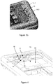
figure 4 présente une vue isométrique du logement d'insertion avec le connecteur coulissant en position d'attente ; - la
figure 5 est une vue de coupe partielle du dispositif de paiement ; - la
figure 6 est une vue de coupe partielle du dispositif de paiement, avec le connecteur également en coupe. - Comme indiqué précédemment, le problème d'insertion et de retrait du terminal de communication est résolu par l'adjonction, au sein du boitier, d'un connecteur mâle mobile en translation. Le principe général de l'invention est décrit en relation avec les
figures 2a et 2b . - La
figure 2a est une vue de coupe de principe de la mise en œuvre du connecteur male mobile en translation. Lafigure 2b représente une vue de dessus. Le connecteur (11) est monté sur un support (13). Le support (13) est mobile dans une direction donnée. Pour ce faire le principe général est de munir le support d'une rainure (15) complémentaire d'une languette (non représentée). Lorsqu'il est posé sur la languette, le support ne peut donc que coulisser dans une seule direction, qui est la direction d'insertion et de retrait du terminal de paiement. La rainure n'est pas obligatoire. Tout autre moyen de coulissement, tel qu'un coulisseau, peut également être utilisé, en lien par exemple avec un rail d'accueil. Lorsqu'il s'agit d'une rainure, la section de celle-ci n'est pas nécessairement parallélépipédique. Cette section peut être semi-circulaire ou encore triangulaire. - Le connecteur (11) pour sa part est relié à une carte mère ou à une carte d'alimentation du dispositif de paiement par l'intermédiaire d'un flex (12). Ce flex (12) permet d'assurer un déplacement du support et une connectivité permanente du connecteur.
- Le support de connecteur, de manière complémentaire est associé à des moyens de rappel (MR)(par exemple un ressort ou une lame ressort), permettant de mettre le support en butée contre une géométrie de butée (une dent de butée) lorsqu'aucun terminal n'est inséré dans le logement de réception. De manière plus précise, lorsqu'aucun terminal n'est dans le logement, le support est poussé en butée afin et est maintenu dans une première position, dite position d'attente. Lorsqu'un terminal est inséré, le terminal exerce une pression sur le support par l'intermédiaire du connecteur male. Le support coulisse donc lors de l'insertion jusqu'à une deuxième position, dite position de fonctionnement. L'action du moyen de rappel est annihilée par la fermeture de la trappe permettant d'insertion du terminal. Bien entendu, ceci est un exemple de mise en œuvre. Il est tout à fait possible de ne pas utiliser de moyens de rappels sans que cela nuise aux avantages procurés par la présente technique.
- L'adjonction du connecteur mâle mobile présente deux avantages : le premier avantage est lié au fait que le connecteur mâle du boitier est visible lorsqu'aucun terminal de communication n'est inséré. Il est ainsi aisé de vérifier l'état de ce connecteur mâle et de détecter ainsi d'une part une détérioration de celui-ci et d'autre part une éventuelle tentative de fraude. Il existe en effet des dispositifs de fraudes tels que des sur connecteurs qui sont posés ou enfichés sur le connecteur mâle existant et qui permettent d'intercepter et/ou de modifier des données transitant sur celui-ci par l'intermédiaire de ce connecteur.
- Le deuxième avantage est lié à l'insertion et au retrait du terminal de communication. En effet le connecteur mâle mobile en translation permet, lors de l'insertion du terminal de communication, d'une part de visualiser l'étape d'insertion et de constater (ou non) que le connecteur mâle s'insère correctement dans le connecteur femelle. Ainsi, on prévient les détériorations tant du connecteur mâle que du connecteur femelle (il se peut en effet que ce soit le connecteur femelle du terminal de communication qui soit détérioré, et cette détérioration peut ne pas être perçue immédiatement par l'utilisateur). En outre, le connecteur mâle mobile en translation permet également une insertion progressive du connecteur mâle dans le connecteur femelle. La mobilité en translation permet d'insérer le terminal de communication dans le même mouvement que le mouvement de recul du connecteur mâle mobile en translation au fur et à mesure de l'insertion. Par ailleurs cet effet progressif peut en outre être augmenté, selon un mode de réalisation, par l'adjonction, entre le connecteur mobile et le fond du boitier, d'une moyen de rappel (de type ressort, lame à ressort) qui permet d'assurer une certaine force de résistance à l'insertion.
- En outre, le connecteur mâle mobile en translation permet, lors de l'extraction du terminal de communication, de faciliter le mouvement de translation du terminal de communication. En effet, la séparation du connecteur femelle du terminal de communication et du connecteur mâle du boitier peut présenter une certaine difficulté (comme on l'a expliqué précédemment). La mobilité du connecteur est une réponse simple et efficace à cette problématique : cette mobilité permet d'effectuer un mouvement de translation simple ; le terminal de communication et le connecteur mobile glisse de concert, en étant emboité l'un dans l'autre jusqu'à un point de butée du connecteur mobile ; cette translation permet de créer un vide, au sein du boitier, autour de la base du terminal de communication. Ce vide peut être avantageusement exploité pour insérer un doigt ou un objet qui est alors utilisé pour pousser le terminal de communication en dehors du boitier. On a donc une extraction en deux temps : un premier temps durant lequel le connecteur accompagne le terminal de communication lors de la translation (lors du glissement) et un deuxième temps au cours duquel l'utilisateur extrait le terminal de communication en poussant la base de celui-ci, de chaque côté du connecteur, en utilisant pour ce faire l'espace laissé libre à l'issue de la glissement. Par ailleurs, en fonction de la longueur de la butée par rapport un fond du boitier, le terminal peut également être extrait en tirant sur le haut du terminal (en exerçant une pression à l'aide de deux doigts sur la tranche du terminal) et en tirant celui-ci.
- Par ailleurs cet effet de glissement préalable peut en outre être augmenté, selon un mode de réalisation, par l'adjonction, entre le connecteur mobile et le fond du boitier, d'une moyen de rappel (de type ressort, lame à ressort) qui permet d'assurer une certaine force de poussé à l'extraction du terminal de communication. Cette force peut ainsi être exercée dès l'ouverture de la trappe d'insertion/extraction du terminal de communication : lorsque la trappe est ouverte, le moyen de rappel peut alors exercer sa force de poussée sans obstacle, pour que le connecteur mâle reprenne une position de départ. Bien entendu, la force de rappel exercée est adaptée selon que l'on souhaite que le connecteur mobile en translation puisse extraire seul le terminal de communication ou bien qu'il ne constitue qu'une aide à l'aide à la poussée du terminal hors du logement.
- On décrit, en relation avec les
figures 3a ,3b ,4 ,5 et 6 un mode de réalisation de l'implantation du connecteur mâle mobile. Dans ce mode de réalisation, il s'agit de permettre l'insertion et le retrait de terminaux de communication de la marque Apple™ comprenant un connecteur de type Lightning™. Le mâle connecteur Lightning™ Apple™ peut coulisser afin de faciliter l'insertion et l'extraction du périphérique hors de son logement (élan et/ou création d'une zone de préhension). - Ce connecteur coulissant (10) comprend un connecteur mâle (11) connecté à une carte mère (non représentée) par l'intermédiaire d'un circuit imprimé flexible (12). Ce connecteur mâle (11) est métallique et est fixé sur une base (13) mobile en translation, en matière plastique. Le connecteur (11) est, dans ce mode de réalisation, fixé à la base (13) mobile par l'intermédiaire par exemple de deux vis trox (14-1, 14-2) située de part et d'autre de la base (13) et de part et d'autre du connecteur (11). Le type de fixation ou de vis utilisé n'a pas nécessairement une grande importance. Cependant, compte tenu des efforts de poussée et de traction exercés, l'utilisation de vis trox peut présenter un avantage pour leur adaptation aux matières plastiques. La base (13), mobile en translation, comprend un socle (14). Pour plus de clarté, il est base et socle sont confondus. Ce socle comprend, en son centre, une rainure (15) qui s'étend longitudinalement, dans l'axe de coulissement du connecteur (10). Cette rainure (15) permet de conformer l'axe de coulissement du connecteur mobile (10). En effet, la base est posée sur une surface plate (16), comprenant une languette (17) conformée pour s'insérer dans la rainure (15) du socle (14) et assurer une bonne stabilité et un mouvement uniquement dans le sens longitudinal. Bien entendu ceci est un mode de réalisation illustratif. D'autres formes, types et nombre de languettes et de rainures peuvent être utilisés. Le socle comprend également deux ailerons de rétention, s'étendant de part et d'autre du socle perpendiculairement à la rainure. Ces deux ailerons sont utilisés pour maintenir le connecteur mobile en place et éviter qu'il ne sorte de son logement de manière inopinée.
- La surface plate (16) du logement de réception se situe dans un plan (18) légèrement abaissé par rapport au plan général (19) d'accueil du terminal de communication au sein du logement. Ceci permet de protéger le plan de translation du connecteur mobile avec une plaque d'occultation (20) qui, par voie de conséquence se situe dans le plan général (19) d'accueil du terminal de communication.
- La surface plate du logement de réception comprend également une dent de butée (21), servant à stopper le mouvement translatif du connecteur mobile (10). Par ailleurs, en bout de course, au niveau de la dent de butée, deux orifices latéraux (22-1, 22-2) sont également aménagés afin de permettre l'extraction du connecteur mobile en cas de besoin (comme une maintenance par exemple, lorsque le connecteur est abimé). Ces deux orifices permettent d'extraire le connecteur à un endroit souhaité, là ou un emplacement est aménagé pour les ailerons de rétention.
Claims (6)
- Dispositif de connexion (10) d'un terminal de communication, dispositif comprenant :- une surface plate (16) ;- un connecteur mâle (11) destiné à se connecter à un connecteur femelle dudit terminal de communication ;- une base (13) mobile, sur laquelle ledit connecteur mâle (11) est fixé, ladite base mobile étant placée sur la surface plate (16) et- une rainure ménagée dans la base (13) mobile et une languette correspondante sur la surface plate (16), qui s'étend longitudinalement le long d'un axe de coulissement, dans lequel ladite base mobile pouvant coulisser sur la surface plate le long de l'axe de coulissement, correspondant à une direction d'insertion et de retrait dudit terminal de communication au sein dudit dispositif.
- Dispositif selon la revendication 1, caractérisé en ce que ladite base comprend en outre au moins un moyen de rappel.
- Dispositif selon la revendication 1, caractérisé en ce que ledit connecteur mâle est un connecteur micro USB.
- Dispositif selon la revendication 1, caractérisé en ce que ledit connecteur mâle est un connecteur Lightning.
- Dispositif selon la revendication 1, caractérisé en ce que ledit connecteur mâle est un connecteur USB de type-C.
- Dispositif de paiement comprenant :- un terminal de paiement ;- un logement d'insertion d'un terminal de communication au sein du terminal de paiement ;- caractérisé en ce qu'il comprend, au sein dudit logement d'insertion, un dispositif de connexion selon l'une quelconque des revendications précédentes.
Applications Claiming Priority (1)
| Application Number | Priority Date | Filing Date | Title |
|---|---|---|---|
| FR1459998A FR3027465B1 (fr) | 2014-10-17 | 2014-10-17 | Dispositif d'insertion de terminal |
Publications (2)
| Publication Number | Publication Date |
|---|---|
| EP3010211A1 EP3010211A1 (fr) | 2016-04-20 |
| EP3010211B1 true EP3010211B1 (fr) | 2019-11-27 |
Family
ID=52273273
Family Applications (1)
| Application Number | Title | Priority Date | Filing Date |
|---|---|---|---|
| EP15190288.9A Active EP3010211B1 (fr) | 2014-10-17 | 2015-10-16 | Dispositif d'insertion de terminal |
Country Status (7)
| Country | Link |
|---|---|
| US (1) | US9648156B2 (fr) |
| EP (1) | EP3010211B1 (fr) |
| BR (1) | BR102015026400A2 (fr) |
| CA (1) | CA2908727C (fr) |
| ES (1) | ES2773582T3 (fr) |
| FR (1) | FR3027465B1 (fr) |
| RU (1) | RU2015144594A (fr) |
Families Citing this family (3)
| Publication number | Priority date | Publication date | Assignee | Title |
|---|---|---|---|---|
| CN107251535A (zh) * | 2014-08-15 | 2017-10-13 | Peri有限公司 | 移动设备保护壳 |
| CN210838302U (zh) * | 2016-10-07 | 2020-06-23 | 菲力尔系统公司 | 电子模块 |
| FR3057382B1 (fr) * | 2016-10-07 | 2018-11-09 | Ingenico Group | Systeme de conversion d'un terminal de paiement electronique mobile en terminal de paiement electronique fixe |
Citations (1)
| Publication number | Priority date | Publication date | Assignee | Title |
|---|---|---|---|---|
| US20130050934A1 (en) * | 2011-08-24 | 2013-02-28 | Hon Hai Precision Industry Co., Ltd. | Docking station |
Family Cites Families (8)
| Publication number | Priority date | Publication date | Assignee | Title |
|---|---|---|---|---|
| US20070263348A1 (en) * | 2005-11-02 | 2007-11-15 | Dei Headquarters Inc. | Versatile portable electronic device docking station with slidable connector |
| ATE483278T1 (de) * | 2006-11-13 | 2010-10-15 | Peiker Acustic Gmbh & Co Kg | Haltevorrichtung für ein elektronisches gerät |
| DE102007037944B4 (de) | 2007-08-11 | 2010-04-08 | Paragon Ag | Cradle für Mobiltelefone |
| EP2396756A4 (fr) * | 2009-02-10 | 2012-07-25 | 4361423 Canada Inc | Appareil et procédé pour transactions commerciales utilisant un dispositif de communication |
| FR2968433B1 (fr) | 2010-12-07 | 2016-06-24 | Cie Ind Et Financiere D'ingenierie Ingenico | Dispositif de paiement electronique apte a recevoir et maintenir un telephone portable. |
| US8848361B2 (en) * | 2011-09-02 | 2014-09-30 | Sdi Technologies | Adjustable docking apparatus |
| US9093849B2 (en) * | 2013-01-07 | 2015-07-28 | Superior Communications, Inc. | Universal charging dock with a wall mount |
| US9665125B2 (en) * | 2014-03-28 | 2017-05-30 | Intel Corporation | Magnetic attachment mechanism for an electronic device |
-
2014
- 2014-10-17 FR FR1459998A patent/FR3027465B1/fr active Active
-
2015
- 2015-10-14 CA CA2908727A patent/CA2908727C/fr active Active
- 2015-10-16 BR BR102015026400A patent/BR102015026400A2/pt not_active Application Discontinuation
- 2015-10-16 RU RU2015144594A patent/RU2015144594A/ru not_active Application Discontinuation
- 2015-10-16 EP EP15190288.9A patent/EP3010211B1/fr active Active
- 2015-10-16 ES ES15190288T patent/ES2773582T3/es active Active
- 2015-10-19 US US14/886,803 patent/US9648156B2/en active Active
Patent Citations (1)
| Publication number | Priority date | Publication date | Assignee | Title |
|---|---|---|---|---|
| US20130050934A1 (en) * | 2011-08-24 | 2013-02-28 | Hon Hai Precision Industry Co., Ltd. | Docking station |
Also Published As
| Publication number | Publication date |
|---|---|
| US20160112558A1 (en) | 2016-04-21 |
| CA2908727C (fr) | 2023-03-14 |
| ES2773582T3 (es) | 2020-07-13 |
| EP3010211A1 (fr) | 2016-04-20 |
| RU2015144594A (ru) | 2017-04-24 |
| CA2908727A1 (fr) | 2016-04-17 |
| US9648156B2 (en) | 2017-05-09 |
| FR3027465B1 (fr) | 2018-04-06 |
| BR102015026400A2 (pt) | 2016-04-19 |
| FR3027465A1 (fr) | 2016-04-22 |
Similar Documents
| Publication | Publication Date | Title |
|---|---|---|
| EP3207596B1 (fr) | Dispositif de solidarisation de câbles de rechargement électrique | |
| EP3010211B1 (fr) | Dispositif d'insertion de terminal | |
| US9313909B1 (en) | Alignment device of a hard disk drive bay | |
| US9246249B2 (en) | Card connector for different specifications of electronic cards | |
| WO2009055062A3 (fr) | Connecteur de carte pour recevoir de multiples cartes | |
| FR2903515A3 (fr) | Ensemble carte memoire | |
| US20180219312A1 (en) | Withdrawable-card-tray position-fixing structure for electronic device | |
| FR2630267A1 (fr) | Dispositif de mise en contact electrique de conducteurs repartis sur deux elements et notamment entre ceux d'une carte a memoire et ceux de son lecteur | |
| FR2714989A1 (fr) | Dispositif de connexion de carte à mémoire. | |
| EP3326108B1 (fr) | Lecteur de carte compact | |
| US7988472B2 (en) | Electronic device | |
| EP0263746A2 (fr) | Système à lecture de cartes d'identification à contacts électriques | |
| EP2525501A1 (fr) | Method and apparatus pertaining to movement of a sim-card tray | |
| EP3513386B1 (fr) | Terminal de paiement électronique avec élément monobloc de lecture de carte magnétique comprenant une lame métallique de glissement, procédé de montage correspondant | |
| EP2661790B1 (fr) | Dispositif électronique avec maintien magnétique d'un composant électronique | |
| FR2966317A1 (fr) | Appareil electronique a accessoire amovible. | |
| BE1024236B9 (fr) | Dispositif d'affichage comprenant au moins un ecran mobile pour utilisation avec ordinateur portable | |
| FR2795194A1 (fr) | Extension pour module electronique de type pcmcia | |
| WO2012168382A1 (fr) | Ensemble usb comportant une clé usb améliorée | |
| FR3059513A1 (fr) | Dispositif d'extraction de carte electronique par effet levier | |
| FR2576156A1 (fr) | Systeme de connexion electrique | |
| FR2976375A1 (fr) | Cle usb amelioree | |
| FR3063561A1 (fr) | Dispositif de support pour terminal de paiement | |
| CN106159496A (zh) | 卡用连接器 | |
| CN104601746A (zh) | 具有卡固持装置的移动终端 |
Legal Events
| Date | Code | Title | Description |
|---|---|---|---|
| PUAI | Public reference made under article 153(3) epc to a published international application that has entered the european phase |
Free format text: ORIGINAL CODE: 0009012 |
|
| AK | Designated contracting states |
Kind code of ref document: A1 Designated state(s): AL AT BE BG CH CY CZ DE DK EE ES FI FR GB GR HR HU IE IS IT LI LT LU LV MC MK MT NL NO PL PT RO RS SE SI SK SM TR |
|
| AX | Request for extension of the european patent |
Extension state: BA ME |
|
| 17P | Request for examination filed |
Effective date: 20161020 |
|
| RBV | Designated contracting states (corrected) |
Designated state(s): AL AT BE BG CH CY CZ DE DK EE ES FI FR GB GR HR HU IE IS IT LI LT LU LV MC MK MT NL NO PL PT RO RS SE SI SK SM TR |
|
| STAA | Information on the status of an ep patent application or granted ep patent |
Free format text: STATUS: EXAMINATION IS IN PROGRESS |
|
| 17Q | First examination report despatched |
Effective date: 20181122 |
|
| RIC1 | Information provided on ipc code assigned before grant |
Ipc: G06F 13/42 20060101ALI20190521BHEP Ipc: H04M 1/04 20060101AFI20190521BHEP Ipc: H04M 1/725 20060101ALI20190521BHEP Ipc: G06Q 20/32 20120101ALI20190521BHEP Ipc: G07F 7/08 20060101ALI20190521BHEP Ipc: G06F 13/40 20060101ALI20190521BHEP Ipc: H01R 24/60 20110101ALI20190521BHEP Ipc: H01R 107/00 20060101ALI20190521BHEP Ipc: G06F 1/16 20060101ALI20190521BHEP |
|
| GRAP | Despatch of communication of intention to grant a patent |
Free format text: ORIGINAL CODE: EPIDOSNIGR1 |
|
| STAA | Information on the status of an ep patent application or granted ep patent |
Free format text: STATUS: GRANT OF PATENT IS INTENDED |
|
| INTG | Intention to grant announced |
Effective date: 20190628 |
|
| GRAS | Grant fee paid |
Free format text: ORIGINAL CODE: EPIDOSNIGR3 |
|
| GRAA | (expected) grant |
Free format text: ORIGINAL CODE: 0009210 |
|
| STAA | Information on the status of an ep patent application or granted ep patent |
Free format text: STATUS: THE PATENT HAS BEEN GRANTED |
|
| AK | Designated contracting states |
Kind code of ref document: B1 Designated state(s): AL AT BE BG CH CY CZ DE DK EE ES FI FR GB GR HR HU IE IS IT LI LT LU LV MC MK MT NL NO PL PT RO RS SE SI SK SM TR |
|
| REG | Reference to a national code |
Ref country code: GB Ref legal event code: FG4D Free format text: NOT ENGLISH |
|
| REG | Reference to a national code |
Ref country code: CH Ref legal event code: EP |
|
| REG | Reference to a national code |
Ref country code: AT Ref legal event code: REF Ref document number: 1208023 Country of ref document: AT Kind code of ref document: T Effective date: 20191215 |
|
| REG | Reference to a national code |
Ref country code: DE Ref legal event code: R096 Ref document number: 602015042416 Country of ref document: DE |
|
| REG | Reference to a national code |
Ref country code: IE Ref legal event code: FG4D Free format text: LANGUAGE OF EP DOCUMENT: FRENCH |
|
| REG | Reference to a national code |
Ref country code: NL Ref legal event code: MP Effective date: 20191127 |
|
| REG | Reference to a national code |
Ref country code: LT Ref legal event code: MG4D |
|
| PG25 | Lapsed in a contracting state [announced via postgrant information from national office to epo] |
Ref country code: NL Free format text: LAPSE BECAUSE OF FAILURE TO SUBMIT A TRANSLATION OF THE DESCRIPTION OR TO PAY THE FEE WITHIN THE PRESCRIBED TIME-LIMIT Effective date: 20191127 Ref country code: SE Free format text: LAPSE BECAUSE OF FAILURE TO SUBMIT A TRANSLATION OF THE DESCRIPTION OR TO PAY THE FEE WITHIN THE PRESCRIBED TIME-LIMIT Effective date: 20191127 Ref country code: LV Free format text: LAPSE BECAUSE OF FAILURE TO SUBMIT A TRANSLATION OF THE DESCRIPTION OR TO PAY THE FEE WITHIN THE PRESCRIBED TIME-LIMIT Effective date: 20191127 Ref country code: BG Free format text: LAPSE BECAUSE OF FAILURE TO SUBMIT A TRANSLATION OF THE DESCRIPTION OR TO PAY THE FEE WITHIN THE PRESCRIBED TIME-LIMIT Effective date: 20200227 Ref country code: FI Free format text: LAPSE BECAUSE OF FAILURE TO SUBMIT A TRANSLATION OF THE DESCRIPTION OR TO PAY THE FEE WITHIN THE PRESCRIBED TIME-LIMIT Effective date: 20191127 Ref country code: NO Free format text: LAPSE BECAUSE OF FAILURE TO SUBMIT A TRANSLATION OF THE DESCRIPTION OR TO PAY THE FEE WITHIN THE PRESCRIBED TIME-LIMIT Effective date: 20200227 Ref country code: GR Free format text: LAPSE BECAUSE OF FAILURE TO SUBMIT A TRANSLATION OF THE DESCRIPTION OR TO PAY THE FEE WITHIN THE PRESCRIBED TIME-LIMIT Effective date: 20200228 Ref country code: LT Free format text: LAPSE BECAUSE OF FAILURE TO SUBMIT A TRANSLATION OF THE DESCRIPTION OR TO PAY THE FEE WITHIN THE PRESCRIBED TIME-LIMIT Effective date: 20191127 |
|
| PG25 | Lapsed in a contracting state [announced via postgrant information from national office to epo] |
Ref country code: RS Free format text: LAPSE BECAUSE OF FAILURE TO SUBMIT A TRANSLATION OF THE DESCRIPTION OR TO PAY THE FEE WITHIN THE PRESCRIBED TIME-LIMIT Effective date: 20191127 Ref country code: IS Free format text: LAPSE BECAUSE OF FAILURE TO SUBMIT A TRANSLATION OF THE DESCRIPTION OR TO PAY THE FEE WITHIN THE PRESCRIBED TIME-LIMIT Effective date: 20200327 Ref country code: HR Free format text: LAPSE BECAUSE OF FAILURE TO SUBMIT A TRANSLATION OF THE DESCRIPTION OR TO PAY THE FEE WITHIN THE PRESCRIBED TIME-LIMIT Effective date: 20191127 |
|
| PG25 | Lapsed in a contracting state [announced via postgrant information from national office to epo] |
Ref country code: AL Free format text: LAPSE BECAUSE OF FAILURE TO SUBMIT A TRANSLATION OF THE DESCRIPTION OR TO PAY THE FEE WITHIN THE PRESCRIBED TIME-LIMIT Effective date: 20191127 |
|
| REG | Reference to a national code |
Ref country code: ES Ref legal event code: FG2A Ref document number: 2773582 Country of ref document: ES Kind code of ref document: T3 Effective date: 20200713 |
|
| PG25 | Lapsed in a contracting state [announced via postgrant information from national office to epo] |
Ref country code: CZ Free format text: LAPSE BECAUSE OF FAILURE TO SUBMIT A TRANSLATION OF THE DESCRIPTION OR TO PAY THE FEE WITHIN THE PRESCRIBED TIME-LIMIT Effective date: 20191127 Ref country code: RO Free format text: LAPSE BECAUSE OF FAILURE TO SUBMIT A TRANSLATION OF THE DESCRIPTION OR TO PAY THE FEE WITHIN THE PRESCRIBED TIME-LIMIT Effective date: 20191127 Ref country code: DK Free format text: LAPSE BECAUSE OF FAILURE TO SUBMIT A TRANSLATION OF THE DESCRIPTION OR TO PAY THE FEE WITHIN THE PRESCRIBED TIME-LIMIT Effective date: 20191127 Ref country code: PT Free format text: LAPSE BECAUSE OF FAILURE TO SUBMIT A TRANSLATION OF THE DESCRIPTION OR TO PAY THE FEE WITHIN THE PRESCRIBED TIME-LIMIT Effective date: 20200419 Ref country code: EE Free format text: LAPSE BECAUSE OF FAILURE TO SUBMIT A TRANSLATION OF THE DESCRIPTION OR TO PAY THE FEE WITHIN THE PRESCRIBED TIME-LIMIT Effective date: 20191127 |
|
| REG | Reference to a national code |
Ref country code: DE Ref legal event code: R097 Ref document number: 602015042416 Country of ref document: DE |
|
| PG25 | Lapsed in a contracting state [announced via postgrant information from national office to epo] |
Ref country code: SM Free format text: LAPSE BECAUSE OF FAILURE TO SUBMIT A TRANSLATION OF THE DESCRIPTION OR TO PAY THE FEE WITHIN THE PRESCRIBED TIME-LIMIT Effective date: 20191127 Ref country code: SK Free format text: LAPSE BECAUSE OF FAILURE TO SUBMIT A TRANSLATION OF THE DESCRIPTION OR TO PAY THE FEE WITHIN THE PRESCRIBED TIME-LIMIT Effective date: 20191127 |
|
| REG | Reference to a national code |
Ref country code: AT Ref legal event code: MK05 Ref document number: 1208023 Country of ref document: AT Kind code of ref document: T Effective date: 20191127 |
|
| PLBE | No opposition filed within time limit |
Free format text: ORIGINAL CODE: 0009261 |
|
| STAA | Information on the status of an ep patent application or granted ep patent |
Free format text: STATUS: NO OPPOSITION FILED WITHIN TIME LIMIT |
|
| 26N | No opposition filed |
Effective date: 20200828 |
|
| PG25 | Lapsed in a contracting state [announced via postgrant information from national office to epo] |
Ref country code: AT Free format text: LAPSE BECAUSE OF FAILURE TO SUBMIT A TRANSLATION OF THE DESCRIPTION OR TO PAY THE FEE WITHIN THE PRESCRIBED TIME-LIMIT Effective date: 20191127 Ref country code: SI Free format text: LAPSE BECAUSE OF FAILURE TO SUBMIT A TRANSLATION OF THE DESCRIPTION OR TO PAY THE FEE WITHIN THE PRESCRIBED TIME-LIMIT Effective date: 20191127 Ref country code: PL Free format text: LAPSE BECAUSE OF FAILURE TO SUBMIT A TRANSLATION OF THE DESCRIPTION OR TO PAY THE FEE WITHIN THE PRESCRIBED TIME-LIMIT Effective date: 20191127 |
|
| PG25 | Lapsed in a contracting state [announced via postgrant information from national office to epo] |
Ref country code: IT Free format text: LAPSE BECAUSE OF FAILURE TO SUBMIT A TRANSLATION OF THE DESCRIPTION OR TO PAY THE FEE WITHIN THE PRESCRIBED TIME-LIMIT Effective date: 20191127 |
|
| REG | Reference to a national code |
Ref country code: CH Ref legal event code: PL |
|
| PG25 | Lapsed in a contracting state [announced via postgrant information from national office to epo] |
Ref country code: LU Free format text: LAPSE BECAUSE OF NON-PAYMENT OF DUE FEES Effective date: 20201016 Ref country code: MC Free format text: LAPSE BECAUSE OF FAILURE TO SUBMIT A TRANSLATION OF THE DESCRIPTION OR TO PAY THE FEE WITHIN THE PRESCRIBED TIME-LIMIT Effective date: 20191127 |
|
| REG | Reference to a national code |
Ref country code: BE Ref legal event code: MM Effective date: 20201031 |
|
| PG25 | Lapsed in a contracting state [announced via postgrant information from national office to epo] |
Ref country code: CH Free format text: LAPSE BECAUSE OF NON-PAYMENT OF DUE FEES Effective date: 20201031 Ref country code: BE Free format text: LAPSE BECAUSE OF NON-PAYMENT OF DUE FEES Effective date: 20201031 Ref country code: LI Free format text: LAPSE BECAUSE OF NON-PAYMENT OF DUE FEES Effective date: 20201031 |
|
| PG25 | Lapsed in a contracting state [announced via postgrant information from national office to epo] |
Ref country code: IE Free format text: LAPSE BECAUSE OF NON-PAYMENT OF DUE FEES Effective date: 20201016 |
|
| REG | Reference to a national code |
Ref country code: GB Ref legal event code: 732E Free format text: REGISTERED BETWEEN 20220127 AND 20220202 |
|
| PG25 | Lapsed in a contracting state [announced via postgrant information from national office to epo] |
Ref country code: TR Free format text: LAPSE BECAUSE OF FAILURE TO SUBMIT A TRANSLATION OF THE DESCRIPTION OR TO PAY THE FEE WITHIN THE PRESCRIBED TIME-LIMIT Effective date: 20191127 Ref country code: MT Free format text: LAPSE BECAUSE OF FAILURE TO SUBMIT A TRANSLATION OF THE DESCRIPTION OR TO PAY THE FEE WITHIN THE PRESCRIBED TIME-LIMIT Effective date: 20191127 Ref country code: CY Free format text: LAPSE BECAUSE OF FAILURE TO SUBMIT A TRANSLATION OF THE DESCRIPTION OR TO PAY THE FEE WITHIN THE PRESCRIBED TIME-LIMIT Effective date: 20191127 |
|
| PG25 | Lapsed in a contracting state [announced via postgrant information from national office to epo] |
Ref country code: MK Free format text: LAPSE BECAUSE OF FAILURE TO SUBMIT A TRANSLATION OF THE DESCRIPTION OR TO PAY THE FEE WITHIN THE PRESCRIBED TIME-LIMIT Effective date: 20191127 |
|
| REG | Reference to a national code |
Ref country code: DE Ref legal event code: R081 Ref document number: 602015042416 Country of ref document: DE Owner name: BANKS AND ACQUIRES INTERNATIONAL HOLDING, FR Free format text: FORMER OWNER: INGENICO GROUP, PARIS, FR Ref country code: DE Ref legal event code: R082 Ref document number: 602015042416 Country of ref document: DE Representative=s name: STUMPF PATENTANWAELTE PARTGMBB, DE |
|
| PGFP | Annual fee paid to national office [announced via postgrant information from national office to epo] |
Ref country code: GB Payment date: 20231020 Year of fee payment: 9 |
|
| PGFP | Annual fee paid to national office [announced via postgrant information from national office to epo] |
Ref country code: ES Payment date: 20231227 Year of fee payment: 9 |
|
| PGFP | Annual fee paid to national office [announced via postgrant information from national office to epo] |
Ref country code: FR Payment date: 20231030 Year of fee payment: 9 Ref country code: DE Payment date: 20231020 Year of fee payment: 9 |