EP3010031B1 - Microscope à particules chargées avec plaque d'ouverture spéciale - Google Patents
Microscope à particules chargées avec plaque d'ouverture spéciale Download PDFInfo
- Publication number
- EP3010031B1 EP3010031B1 EP14189135.8A EP14189135A EP3010031B1 EP 3010031 B1 EP3010031 B1 EP 3010031B1 EP 14189135 A EP14189135 A EP 14189135A EP 3010031 B1 EP3010031 B1 EP 3010031B1
- Authority
- EP
- European Patent Office
- Prior art keywords
- specimen
- aperture
- aperture plate
- image
- microscope
- Prior art date
- Legal status (The legal status is an assumption and is not a legal conclusion. Google has not performed a legal analysis and makes no representation as to the accuracy of the status listed.)
- Active
Links
- 239000002245 particle Substances 0.000 title claims description 28
- 238000009826 distribution Methods 0.000 claims description 32
- 238000000034 method Methods 0.000 claims description 25
- 238000003384 imaging method Methods 0.000 claims description 24
- 230000005855 radiation Effects 0.000 claims description 18
- 230000004907 flux Effects 0.000 claims description 16
- 230000007246 mechanism Effects 0.000 claims description 12
- 230000033001 locomotion Effects 0.000 claims description 11
- 230000004044 response Effects 0.000 claims description 7
- 230000006870 function Effects 0.000 description 35
- 230000004075 alteration Effects 0.000 description 14
- 230000000694 effects Effects 0.000 description 11
- 238000010894 electron beam technology Methods 0.000 description 9
- 150000002500 ions Chemical class 0.000 description 9
- 239000000523 sample Substances 0.000 description 9
- 230000008569 process Effects 0.000 description 8
- 238000004458 analytical method Methods 0.000 description 7
- 238000001228 spectrum Methods 0.000 description 7
- 238000012546 transfer Methods 0.000 description 7
- 238000013459 approach Methods 0.000 description 6
- 230000005540 biological transmission Effects 0.000 description 5
- 238000013016 damping Methods 0.000 description 5
- 238000005286 illumination Methods 0.000 description 5
- 230000001976 improved effect Effects 0.000 description 5
- 238000012545 processing Methods 0.000 description 5
- 238000012360 testing method Methods 0.000 description 5
- 101100228469 Caenorhabditis elegans exp-1 gene Proteins 0.000 description 4
- 240000007509 Phytolacca dioica Species 0.000 description 4
- 238000001514 detection method Methods 0.000 description 4
- 238000000386 microscopy Methods 0.000 description 4
- 230000003287 optical effect Effects 0.000 description 4
- 230000015572 biosynthetic process Effects 0.000 description 3
- 230000001419 dependent effect Effects 0.000 description 3
- 238000013461 design Methods 0.000 description 3
- 238000005430 electron energy loss spectroscopy Methods 0.000 description 3
- 239000007789 gas Substances 0.000 description 3
- 238000010884 ion-beam technique Methods 0.000 description 3
- 230000001788 irregular Effects 0.000 description 3
- 239000011159 matrix material Substances 0.000 description 3
- 238000005259 measurement Methods 0.000 description 3
- 241000252073 Anguilliformes Species 0.000 description 2
- -1 Ga or He ions) Chemical class 0.000 description 2
- 230000008901 benefit Effects 0.000 description 2
- 238000004422 calculation algorithm Methods 0.000 description 2
- 238000005136 cathodoluminescence Methods 0.000 description 2
- 238000001493 electron microscopy Methods 0.000 description 2
- 238000002149 energy-dispersive X-ray emission spectroscopy Methods 0.000 description 2
- 230000007613 environmental effect Effects 0.000 description 2
- 238000005530 etching Methods 0.000 description 2
- 238000000605 extraction Methods 0.000 description 2
- 229910052734 helium Inorganic materials 0.000 description 2
- 230000006872 improvement Effects 0.000 description 2
- 230000010354 integration Effects 0.000 description 2
- 238000011835 investigation Methods 0.000 description 2
- 238000001888 ion beam-induced deposition Methods 0.000 description 2
- 230000001678 irradiating effect Effects 0.000 description 2
- 238000003754 machining Methods 0.000 description 2
- 229910052751 metal Inorganic materials 0.000 description 2
- 239000002184 metal Substances 0.000 description 2
- 238000003801 milling Methods 0.000 description 2
- 230000000116 mitigating effect Effects 0.000 description 2
- 230000004048 modification Effects 0.000 description 2
- 238000012986 modification Methods 0.000 description 2
- 238000000059 patterning Methods 0.000 description 2
- 230000010363 phase shift Effects 0.000 description 2
- BASFCYQUMIYNBI-UHFFFAOYSA-N platinum Chemical compound [Pt] BASFCYQUMIYNBI-UHFFFAOYSA-N 0.000 description 2
- 238000005070 sampling Methods 0.000 description 2
- 238000004088 simulation Methods 0.000 description 2
- 241000894007 species Species 0.000 description 2
- 230000003595 spectral effect Effects 0.000 description 2
- 238000004611 spectroscopical analysis Methods 0.000 description 2
- 230000003068 static effect Effects 0.000 description 2
- ZOKXTWBITQBERF-UHFFFAOYSA-N Molybdenum Chemical compound [Mo] ZOKXTWBITQBERF-UHFFFAOYSA-N 0.000 description 1
- 238000003917 TEM image Methods 0.000 description 1
- 238000010521 absorption reaction Methods 0.000 description 1
- 238000009825 accumulation Methods 0.000 description 1
- 230000009471 action Effects 0.000 description 1
- 230000003416 augmentation Effects 0.000 description 1
- 230000003190 augmentative effect Effects 0.000 description 1
- 230000009286 beneficial effect Effects 0.000 description 1
- 230000000903 blocking effect Effects 0.000 description 1
- 238000004364 calculation method Methods 0.000 description 1
- 230000008859 change Effects 0.000 description 1
- 238000004040 coloring Methods 0.000 description 1
- 239000002131 composite material Substances 0.000 description 1
- 150000001875 compounds Chemical class 0.000 description 1
- 238000012885 constant function Methods 0.000 description 1
- 239000002826 coolant Substances 0.000 description 1
- 238000001816 cooling Methods 0.000 description 1
- 238000012937 correction Methods 0.000 description 1
- 230000001186 cumulative effect Effects 0.000 description 1
- 230000007423 decrease Effects 0.000 description 1
- 230000003247 decreasing effect Effects 0.000 description 1
- 238000000151 deposition Methods 0.000 description 1
- 230000008021 deposition Effects 0.000 description 1
- 238000009795 derivation Methods 0.000 description 1
- 230000001627 detrimental effect Effects 0.000 description 1
- 230000009977 dual effect Effects 0.000 description 1
- 230000002708 enhancing effect Effects 0.000 description 1
- 238000001914 filtration Methods 0.000 description 1
- 229910052733 gallium Inorganic materials 0.000 description 1
- 239000001307 helium Substances 0.000 description 1
- 238000011065 in-situ storage Methods 0.000 description 1
- 238000013507 mapping Methods 0.000 description 1
- 239000000463 material Substances 0.000 description 1
- 230000008078 mathematical effect Effects 0.000 description 1
- 238000007620 mathematical function Methods 0.000 description 1
- 229910052750 molybdenum Inorganic materials 0.000 description 1
- 239000011733 molybdenum Substances 0.000 description 1
- 238000005457 optimization Methods 0.000 description 1
- 230000000737 periodic effect Effects 0.000 description 1
- 230000002093 peripheral effect Effects 0.000 description 1
- 238000005424 photoluminescence Methods 0.000 description 1
- 230000000704 physical effect Effects 0.000 description 1
- 229910052697 platinum Inorganic materials 0.000 description 1
- 239000002244 precipitate Substances 0.000 description 1
- 239000002243 precursor Substances 0.000 description 1
- 230000001902 propagating effect Effects 0.000 description 1
- 238000001878 scanning electron micrograph Methods 0.000 description 1
- 238000000851 scanning transmission electron micrograph Methods 0.000 description 1
- 238000001350 scanning transmission electron microscopy Methods 0.000 description 1
- 239000004065 semiconductor Substances 0.000 description 1
- 239000007787 solid Substances 0.000 description 1
- 238000003860 storage Methods 0.000 description 1
- 230000003319 supportive effect Effects 0.000 description 1
- 230000002123 temporal effect Effects 0.000 description 1
- 238000012876 topography Methods 0.000 description 1
- 238000004627 transmission electron microscopy Methods 0.000 description 1
Images

Classifications
-
- H—ELECTRICITY
- H01—ELECTRIC ELEMENTS
- H01J—ELECTRIC DISCHARGE TUBES OR DISCHARGE LAMPS
- H01J37/00—Discharge tubes with provision for introducing objects or material to be exposed to the discharge, e.g. for the purpose of examination or processing thereof
- H01J37/02—Details
- H01J37/21—Means for adjusting the focus
-
- H—ELECTRICITY
- H01—ELECTRIC ELEMENTS
- H01J—ELECTRIC DISCHARGE TUBES OR DISCHARGE LAMPS
- H01J37/00—Discharge tubes with provision for introducing objects or material to be exposed to the discharge, e.g. for the purpose of examination or processing thereof
- H01J37/26—Electron or ion microscopes; Electron or ion diffraction tubes
- H01J37/261—Details
- H01J37/263—Contrast, resolution or power of penetration
-
- H—ELECTRICITY
- H01—ELECTRIC ELEMENTS
- H01J—ELECTRIC DISCHARGE TUBES OR DISCHARGE LAMPS
- H01J37/00—Discharge tubes with provision for introducing objects or material to be exposed to the discharge, e.g. for the purpose of examination or processing thereof
- H01J37/26—Electron or ion microscopes; Electron or ion diffraction tubes
- H01J37/28—Electron or ion microscopes; Electron or ion diffraction tubes with scanning beams
-
- H—ELECTRICITY
- H01—ELECTRIC ELEMENTS
- H01J—ELECTRIC DISCHARGE TUBES OR DISCHARGE LAMPS
- H01J2237/00—Discharge tubes exposing object to beam, e.g. for analysis treatment, etching, imaging
- H01J2237/04—Means for controlling the discharge
- H01J2237/045—Diaphragms
- H01J2237/0451—Diaphragms with fixed aperture
- H01J2237/0453—Diaphragms with fixed aperture multiple apertures
-
- H—ELECTRICITY
- H01—ELECTRIC ELEMENTS
- H01J—ELECTRIC DISCHARGE TUBES OR DISCHARGE LAMPS
- H01J2237/00—Discharge tubes exposing object to beam, e.g. for analysis treatment, etching, imaging
- H01J2237/21—Focus adjustment
- H01J2237/216—Automatic focusing methods
-
- H—ELECTRICITY
- H01—ELECTRIC ELEMENTS
- H01J—ELECTRIC DISCHARGE TUBES OR DISCHARGE LAMPS
- H01J2237/00—Discharge tubes exposing object to beam, e.g. for analysis treatment, etching, imaging
- H01J2237/26—Electron or ion microscopes
- H01J2237/28—Scanning microscopes
- H01J2237/2802—Transmission microscopes
Definitions
- the invention relates to a Charged Particle Microscope, comprising:
- the invention also relates to various innovative methods of using such a microscope.
- Charged particle microscopy is a well-known and increasingly important technique for imaging microscopic objects, particularly in the form of electron microscopy.
- the basic genus of electron microscope has undergone evolution into a number of well-known apparatus species, such as the Transmission Electron Microscope (TEM), Scanning Electron Microscope (SEM), and Scanning Transmission Electron Microscope (STEM), and also into various sub-species, such as so-called “dual-beam” tools (e.g . a FIB-SEM), which additionally employ a "machining" Focused Ion Beam (FIB), allowing supportive activities such as ion-beam milling or Ion-Beam-Induced Deposition (IBID), for example. More specifically:
- charged particle microscopy can also be performed using other species of charged particle.
- the phrase "charged particle” should be broadly interpreted as encompassing electrons, positive ions (e.g . Ga or He ions), negative ions, protons and positrons, for instance.
- positive ions e.g . Ga or He ions
- negative ions e.g . Ga or He ions
- protons e.g .
- positrons e.g.
- some further information can, for example, be gleaned from sources such as the following:
- a charged particle microscope may also have other functionalities, such as performing spectroscopy, examining diffractograms, performing (localized) surface modification (e.g . milling, etching, deposition), etc.
- a Charged Particle Microscope will comprise at least the following components:
- such an apparatus will typically further comprise:
- the invention may - by way of example - sometimes be set forth in the specific context of electron microscopy. However, such simplification is intended solely for clarity/illustrative purposes, and should not be interpreted as limiting.
- the abovementioned aperture plate is often referred to as a "condenser aperture” or "aberration control aperture", for example, and it conventionally has the function of limiting the extent/diameter/size of the beam cross-section; this is generally beneficial for image resolution, because charged particles that are more off-axis tend to be less well-focused on the specimen due to lens aberrations (such as spherical and chromatic aberration, for example) in the (probe-forming lens(es)) of the illuminator.
- lens aberrations such as spherical and chromatic aberration, for example
- the aperture region will basically consist of a relatively large round hole that is centered on the (particle-)optical axis.
- a plate is positioned so as to lie proximal to the final probe-forming lens (objective lens) of the illuminator.
- the in-plane (Cartesian XY) position of the aperture region can be fine-tuned to exactly align it with the center of the probe-forming lens.
- the microscope user can switch mechanically between a set of apertures of different sizes, in order to switch between different resolutions and probe currents.
- the improved microscope design should be more versatile than prior-art apparatus, and that it should allow more accurate microscopy results to be obtained.
- said aperture region comprises a distribution of a plurality of holes, each of which is smaller than a diameter of the beam incident on the aperture plate, characterized in that said aperture plate is held by an exchanger mechanism that can be selectively invoked to place a variety of different aperture plates in said beam path.
- a multi-holed aperture region as referred to above serves to convert a singular incident beam into a plurality of emergent sub-beams, the cross-sectional shape of a given sub-beam being dependent upon the shape of the hole (in said distribution) from which it emerges.
- the effect of such an aperture region can be set forth in terms of mathematical considerations, and also in terms of physical considerations. As regards a general mathematical analysis, the following can be noted:
- the form and size of the collective non-overlapped penumbrae can be similarly manipulated, so that the first-order information also becomes potentially richer. Extraction of information from such higher-order overlap effects can be somewhat likened to extraction of information from interference fringes or wave beats, for example.
- the employed aperture plate is used to perform an autofocus operation for the beam on the specimen.
- automatic focusing is enacted by performing a so-called "focus series", whereby a test series (train) of images of a test object (such as a particular feature of a specimen) is made through best focus, e.g . from slight over-focus, through best focus, to slight under-focus; analysis of this series then reveals the axial position of best focus as being the focal position of smallest image diameter of the employed test object.
- approaches (i) and/or (ii) can be used in conjunction with an associated (once-off or periodic) pre-calibration routine, which allows an observed degree of image defocus to be efficiently translated into a corresponding correction in axial focal position.
- the innovative aperture plate is used during a scanning motion of the beam across at least a portion of the specimen to perform an operation selected from the group comprising:
- a significant advantage of the autofocus embodiment set forth in the previous paragraph is that it basically allows on-the-fly point-by-point focusing during a beam scan (since a time-consuming focus series is obviated). As a result, focus information per point (pixel/sector) of a scan path can be obtained in (substantially) real time, and this allows the following:
- the employed aperture plate is used to improve resolution of an image of the specimen.
- an effect of using such an aperture plate is to modify a source function for the illuminator by superimposing thereupon a block function (filter function) that has a first value (e.g . 1) at locations corresponding to the holes in the aperture plate, and a second value (e.g . 0) at blocking locations of the aperture plate.
- CTF Contrast Transfer Function
- the CTF can be manipulated so as to be augmented at higher spatial frequencies - where it would otherwise tend toward zero in the case of an unmodified source function.
- Such augmentation leads to improved spatial resolution. See Embodiment 4 below, for example.
- an equivalent effect occurs in a mathematical function describing the probe profile/behavior at the specimen. Such a function may generically be referred to as an "imaging function".
- Sparse scanning is a technique whereby, instead of visiting all possible pixel positions along a specimen-filling scan path, one instead only visits a relatively sparse set of such positions.
- Such a scanning technique is advantageous in that it is necessarily (much) faster than a full scan, and entails much less radiation exposure of the specimen; however, it is, in principle, disadvantageous in that it produces a (much) smaller data set from which to construct an image, and this typically translates to lower image resolution.
- This embodiment exploits the fact that the illuminating beam in a transmission-type microscope is not exactly collimated/parallel, but generally contains a (relatively narrow) distribution of illumination angles.
- a multi-holed aperture plate - which, for the current embodiment, is advantageously disposed in/proximal a beam cross-over, for example - this continuous distribution of illumination angles can be discretized into a collection of distinct illumination angle ranges - each of which is relatively narrow by virtue of the fact that it is formed as a result of passage through a relatively small hole. Consequently, a specimen illuminated in this way will be concurrently illuminated by plural distinct sub-beams, each with its own associated (median) beam tilt.
- each of these sub-beams will produce its own laterally-shifted sub-image, with a lateral shift whose magnitude and sign depends on the magnitude and sign of the progenitor sub-beam's tilt; on the other hand, for a focused image, all such lateral shifts will essentially be zero.
- Concurrent illumination of the specimen by a plurality of such sub-beams will thus produce an associated plurality of individually laterally shifted sub-images, which combine to form a convoluted resultant image. Mathematical deconvolution of this image will then yield the magnitude and sign of the associated defocus.
- focus information can be gleaned from a single imaging session (using concurrent plural sub-beam tilts) rather than having to be determined using multiple imaging sessions (using a temporal sequence of individually adjusted beam tilts) - thus saving time, improving throughput, and reducing the cumulative radiation dose to the specimen.
- the invention offers considerable flexibility/freedom as regards the form given to the innovative aperture region.
- geometrical parameters of the distribution such as the form of the "grid” on which nodes of the distribution are located (e.g . hexagonal, orthogonal, polar, irregular, etc .), the size of the "cells" in the grid, the filling factor of said cells, etc . - one can also (freely) choose parameters of the holes - such as hole size, hole shape, hole orientation, etc.
- the present invention provides manifold extra degrees of freedom that are not available with a conventional set-up, and that can be tuned so as to finely manipulate the aforementioned PSF / Fourier spectrum / CTF / imaging function.
- the distribution comprises at least two holes that are mutually different as regards at least one of hole size, hole shape, and hole orientation.
- Such an example allows maximal flexibility in tailoring the (block/filter function of the) employed aperture plate to the needs of a given situation.
- Said variety of apertures plate may, if desired, contain conventional-type aperture plates in addition to various versions of the innovative type of aperture plate of the present invention.
- Having a variety of aperture plates in situ within the vacuum environment of the CPM is advantageous, since such plates do not have to be moved through airlocks before/after each use.
- the CPM user can easily switch between different aperture plates as his needs change, e.g. if he starts to examine a different type of specimen, or conduct a different type of analysis (imaging, diffractogram capture, spectroscopy), or perform a calibration routine, etc.
- said exchanger mechanism is selected from the group comprising:
- this may, for example, be a rotatable carrousel or a slidable sled, which can be driven/positioned by a motor (such as a stepper motor, for instance).
- a motor such as a stepper motor, for instance.
- said gripper this may, for example, be a SCARA robot or other type of mechanical arm/hand mechanism that cooperates with a rack/stack having slot positions in which various aperture plates are stored. If desired, such mechanisms can be fully automated, e.g.
- an electronic lookup table the storage positions of various types of aperture plate, and connecting the relevant actuator of the exchanger mechanism (carrousel/sled driver, robot arm, rack/stack elevator, etc .) to a computer controller that can consult said lookup table in response to an input on a user interface (such as selection of an icon on a (touch)screen, for example) and send appropriate control commands to said actuator so as to position a selected aperture plate in the beam path.
- a user interface such as selection of an icon on a (touch)screen, for example
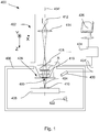
- FIG. 1 is a highly schematic depiction of an embodiment of a CPM according to the present invention; more specifically, it shows an embodiment of a scanning-type microscope 400, which, in this case, is a SEM (though, in the context of the current invention, it could just as validly be an ion-based microscope, for example).
- the microscope 400 comprises a particle-optical column 402, which produces a beam 404 of input charged particles (in this case, an electron beam) that propagates along a particle-optical axis 404'.
- the particle-optical column 402 is mounted on a vacuum chamber 406, which comprises a specimen holder / stage 408 for holding a specimen 410.
- the vacuum chamber 406 is evacuated using vacuum pumps (not depicted). With the aid of voltage source 422, the specimen holder 408, or at least the specimen 410, may, if desired, be biased (floated) to an electrical potential with respect to ground.
- the particle-optical column 402 comprises an electron source 412 (such as a Schottky gun), lenses 414, 416 to focus the electron beam 404 onto the specimen 410, and a deflection unit 418 (to perform beam steering / scanning of the beam 404).
- the apparatus 400 further comprises a controller / computer processing apparatus 424 for controlling inter alia the deflection unit 418, lenses 414, 416 and detectors 420, 428 and displaying information gathered from the detectors 420, 428 on a display unit 426.
- items 414, 416 and 418 may be regarded as being comprised in the illuminator referred to above.
- the detectors 420, 428 are chosen from a variety of possible detector types that can be used to examine different types of output radiation flux emanating from the specimen 410 in response to irradiation by the input beam 404. In the apparatus depicted here, the following detector choices have been made:
- both detectors 420 and 428 are used to examine electrons; however, this is purely a design/implementation choice and, if desired, one could also elect to detect other types of output radiation flux emanating from the specimen 410 (e.g . X-rays, cathodoluminescence) in addition, or as an alternative, to electrons.
- output radiation - comprising, for example, a flux of X-rays, infrared/visible/ultraviolet light, secondary electrons and or backscattered (BS) electrons - emanates from the specimen 410. Since such output radiation is position-sensitive (due to said scanning motion), the information obtained from the detectors 420, 428 will also be position-dependent. This fact allows the output of detector 420 to be used to produce (for example) a backscattered electron image of (part of) the specimen 410, which image is basically a map of an output of detector 420 as a function of scan-path position on the specimen 410.
- BS backscattered
- processing may include operations such as combining, integrating, subtracting, false colouring, edge enhancing, and other processing known to the skilled artisan.
- automated recognition processes e.g . as used for particle analysis may be included in such processing.
- an aperture plate A of a type as hereabove set forth (e.g . as elucidated in Embodiment 2) is (removably/adjustably) mounted in the illuminator of the CPM 400; in this case, the aperture plate A is disposed proximal to the final lens element 416.
- the aperture plate A will be mounted on a holder (not depicted), of an exchanger type as referred to above.
- the beam 404 When the beam 404 is on, it will pass through the multiple holes of the aperture region of the plate A (see respective items 54, 52 in Figures 2A , 2B , for example), and will be sub-divided into a plurality of sub-beams - thereby becoming "patterned" according to the particular distribution/properties of said holes. As set forth above/below, such patterning allows various useful mathematical/physical effects to be achieved.
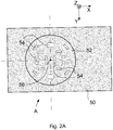
- FIG. 2A renders a plan view of a particular example of an aperture plate A suitable for use in the current invention.
- the plate A is, for example, comprised of a metal sheet 50 (e.g . platinum or molybdenum), with a thickness of the order of about 0.1 mm and lateral dimensions (diameter) of the order of about 3 mm x 3 mm, for instance.
- a metal sheet 50 e.g . platinum or molybdenum
- lateral dimensions (diameter) of the order of about 3 mm x 3 mm for instance.
- Within the area of the sheet 50 is an aperture region 52, corresponding to an intended footprint of the charged-particle beam that will impinge upon the plate A when it is in use; as here depicted, the aperture region 52 is circular, with a diameter of the order of about 0.1 mm, for example.
- a distribution of a plurality of (relatively small) holes 54 which, in this case, are of various shapes, sizes and orientations; although the depicted holes 54 are rectangular, they could also have other forms, such as circular, triangular, hexagonal, etc. Note that, in the current instance, the distribution of holes 54 demonstrates non-isometry relative to the barycenter 56 of the distribution (also the center of the aperture region 52, as here depicted).
- the holes 54 will typically have a width of the order of about a few (tens of) microns.
- aperture plate A When the aperture plate A is in use in a CPM, it is nominally positioned such that the point 56 (approximately) lies upon the particle-optical axis of the CPM's illuminator ( e.g . axis 404' of Figure 1 , or axis 8 of Figure 3 ). An incident particle beam propagating along said particle-optical axis will be selectively eclipsed by the plate A, with beam transmission only occurring through holes 54. In this way, aperture plate A acts as a "patterning plate” or spatial filter, and serves to subdivide an incident beam into a plurality of emergent sub-beams.
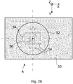
- Figure 2B shows a variation of the subject of Figure 2A that is also an admissible embodiment of the present invention.
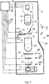
- Figure 3 is a highly schematic depiction of an embodiment of another CPM according to the current invention; more specifically, it shows an embodiment of a transmission-type microscope M, which, in this case, is a TEM/STEM (though, in the context of the current invention, it could just as validly be an ion-based microscope, for example).
- an electron source 4 such as a Schottky gun, for example
- This illuminator 6 has an electron-optical axis 8, and will generally comprise a variety of electrostatic / magnetic lenses, (scan) deflectors, correctors (such as stigmators), etc .; typically, it can also comprise a condenser system (the whole of item 6 is sometimes referred to as "a condenser system").
- the specimen P is held on a specimen holder 10 that can be positioned in multiple degrees of freedom by a positioning device (stage) 12; for example, the specimen holder 10 may comprise a finger that can be moved ( inter alia ) in the XY plane (see the depicted Cartesian coordinate system; typically, motion parallel to Z and tilt about X/Y will also be possible). Such movement allows different parts of the specimen P to be irradiated / imaged / inspected by the electron beam traveling along axis 8 (in the Z direction) (and/or allows scanning motion to be performed, as an alternative to beam scanning).
- An optional cooling device 14 is in intimate thermal contact with the specimen holder 10, and is capable of maintaining the latter at cryogenic temperatures, e.g . using a circulating cryogenic coolant to achieve and maintain a desired low temperature.
- the (focused) electron beam traveling along axis 8 will interact with the specimen P in such a manner as to cause various types of "stimulated” radiation to emanate from the specimen P, including (for example) secondary electrons, backscattered electrons, X-rays and optical radiation (cathodoluminescence).
- various types of "stimulated” radiation including (for example) secondary electrons, backscattered electrons, X-rays and optical radiation (cathodoluminescence).
- one or more of these radiation types can be detected with the aid of analysis device 22, which might be a combined scintillator/photomultiplier or EDX (Energy-Dispersive X-Ray Spectroscopy) module, for instance; in such a case, an image could be constructed using basically the same principle as in a SEM.
- an imaging system combined objective/projection lens 24 which will generally comprise a variety of electrostatic / magnetic lenses, deflectors, correctors (such as stigmators), etc.
- this imaging system 24 can focus the transmitted electron flux onto a fluorescent screen 26, which, if desired, can be retracted/withdrawn (as schematically indicated by arrows 28) so as to get it out of the way of axis 8.
- An image (or diffractogram) of (part of) the specimen P will be formed by imaging system 24 on screen 26, and this may be viewed through viewing port 30 located in a suitable part of the wall 2.
- the retraction mechanism for screen 26 may, for example, be mechanical and/or electrical in nature, and is not depicted here.
- spectroscopic apparatus C can also be integrated into the imaging system 24.
- controller 50 is connected to various illustrated components via control lines (buses) 50'.
- This controller 50 can provide a variety of functions, such as synchronizing actions, providing setpoints, processing signals, performing calculations, and displaying messages/information on a display device (not depicted).
- the (schematically depicted) controller 50 may be (partially) inside or outside the enclosure 2, and may have a unitary or composite structure, as desired.
- the interior of the enclosure 2 does not have to be kept at a strict vacuum; for example, in a so-called "Environmental TEM/STEM", a background atmosphere of a given gas is deliberately introduced/maintained within the enclosure 2.
- the skilled artisan will also understand that, in practice, it may be advantageous to confine the volume of enclosure 2 so that, where possible, it essentially hugs the axis 8, taking the form of a small tube (e.g. of the order of 1 cm in diameter) through which the employed electron beam passes, but widening out to accommodate structures such as the source 4, specimen holder 10, screen 26, camera C, detection device C', spectroscopic apparatus C", etc .
- a small tube e.g. of the order of 1 cm in diameter
- an aperture plate A of a type as hereabove set forth is (removably/adjustably) mounted in the illuminator 6 of the CPM M; in this case, the aperture plate A is disposed at/proximal a beam cross-over (not depicted) in the illuminator 6.
- the aperture plate A is mounted on an exchanger-type holder (not depicted).
- G the transverse position of the electron wave at the lens (which corresponds to the transverse momentum after the lens). If one neglects the (irrelevant) dependence on time and axial coordinate z (or axial momentum G z ), ⁇ 0 (G) is a constant function inside the beam diameter.
- the diameter of the incident wave is taken into account by an aperture function A(G).
- ⁇ 0 G A G
- A(G) will be modified such that A(G) also equals 0 at the spatial frequencies blocked by the inventive aperture.
- an appropriate choice is made for the distribution of holes in the inventive aperture (i.e. when a proper choice is used for the sub-regions where A(G) is zero) it is possible to create a ⁇ (x) which has sharper edges/features than a ⁇ (x) obtained with a conventional aperture (that is, with an A(G) that is only non-zero in one single area).
- Such sharper edges/features lead to better image resolution when the probe profile ⁇ (x) is properly deconvoluted from the SEM/STEM image.
- the recorded intensity at an image detector is proportional to the convolution (*) of ⁇ with its complex conjugate:
- the triple dots ( ⁇ ) represent terms quadratic in ⁇ and ⁇ , which can be neglected.
- the factor cos [2 ⁇ [G)] is called the Amplitude Contrast Transfer Function
- the factor sin [2 ⁇ (G)] is called the Phase Contrast Transfer Function.
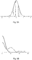
- the RMS (Root Mean Square) width is q 0 .
- P(G) A G ⁇ exp ⁇ 1 ⁇ 2 G / q 0 2 q 0 2 2 ⁇ ⁇ 1 / 2
- E S (G) with the inventive aperture will give less damping at higher frequencies than the conventional E S (G). This improves the spatial resolution.
- R( x ) is a user-defined function that maximizes the prior probability for a desired intensity distribution.
- h is dependent on the distance from the imaged object to the inventive patterned aperture (working distance). Measuring the kernel h d for a given working distance d and then applying the reconstruction algorithm that solves for (5) leads to an image with sharper features for the regions that are located at distance d .
- the local sharpness itself can be determined from the strength of image edge responses, among other approaches, and the corresponding distance/depth value assigned to it.
- the kernel h is characterized with high-resolution - e.g. using measurements, theoretical knowledge or simulation - one can recover a super-resolved image from the observed image using compressive sensing techniques.
Claims (11)
- Microscope à particules chargées comprenant :- un support de spécimen (408) pour supporter un spécimen (410) ;- une source (412) pour produire un faisceau de particules chargées ;- un illuminateur pour diriger ledit faisceau de manière à irradier le spécimen ;- un détecteur (420, 428) pour détecter un flux de radiation émanant du spécimen en réponse à ladite irradiation,lequel illuminateur comprend :- une plaque d'ouverture (A ; 50) comprenant une zone d'ouverture dans un trajet dudit faisceau, pour définir une géométrie du faisceau avant son affectation audit spécimen, ladite zone d'ouverture comprenant une distribution d'une pluralité de trous (54), dont chacun est plus petit qu'un diamètre du faisceau arrivant sur la plaque d'ouverture,caractérisé en ce que ladite plaque d'ouverture est maintenue par un mécanisme échangeur qui peut être appelé de manière sélective à placer une variété de plaques d'ouverture différentes dans ledit trajet de faisceau.
- Microscope, selon la revendication 1, dans lequel, dans ladite pluralité de trous, il y a au moins deux trous qui sont mutuellement différents si l'on considère une propriété sélectionnée dans le groupe comprenant la taille des trous, la forme des trous, l'orientation des trous et des combinaisons de ceux-ci.
- Microscope, selon la revendication 1 ou 2, dans lequel ladite distribution prouve une non-isométrie par rapport à un barycentre associé.
- Microscope, selon la revendication 1, dans lequel ledit mécanisme échangeur est choisi dans le groupe comprenant :- un bac comprenant un certain nombre de positions de support, dont chacune peut être équipée d'une plaque d'ouverture, le bac pouvant être déplacé de manière à placer différentes positions de support dans ledit trajet de faisceau ;- une pince fonctionnant en collaboration avec une collection de plaques d'ouverture, la pince étant capable d'extraire une plaque d'ouverture donnée de ladite collection et de la positionner dans ledit trajet de faisceau.
- Microscope, selon la revendication 1 ou 4, dans lequel ledit mécanisme échangeur est équipé d'une collection de plaques d'ouverture dont chacune comprend un mode de réalisation différent de ladite distribution.
- Procédé d'utilisation d'un microscope à particules chargées comprenant les étapes suivantes :- mise en place d'un spécimen sur un support de spécimen ;- direction d'un faisceau de particules chargées à partir d'une source à travers un illuminateur afin d'irradier le spécimen ;- utilisation d'un détecteur pour détecter un flux de radiation émanant du spécimen en réponse à ladite irradiation, comprenant en particulier l'étape suivante :- mise en place d'une plaque d'ouverture comprenant une zone d'ouverture dans un trajet du faisceau pour définir une géométrie du faisceau avant son affectation au spécimen, ladite zone d'ouverture comprenant une distribution d'une pluralité de trous, dont chacun est plus petit qu'un diamètre du faisceau arrivant sur la plaque d'ouverture,caractérisé en ce que ladite plaque d'ouverture est maintenue par un mécanisme échangeur qui peut être appelé de manière sélective à placer une variété de plaques d'ouverture différentes dans ledit trajet de faisceau.
- Procédé, selon la revendication 6, dans lequel ladite plaque d'ouverture est utilisée pour réaliser une opération de mise au point automatique pour le faisceau sur le spécimen.
- Procédé, selon la revendication 7, dans lequel ladite plaque d'ouverture est utilisée pendant un mouvement de balayage du faisceau à travers au moins une portion du spécimen pour réaliser une opération choisie dans le groupe comprenant :- l'estimation d'un profil topographique pour une surface de ladite portion sollicitée par le faisceau ;- la production d'une image de ladite portion possédant un état de mise au point essentiellement uniforme pour tous points qu'elle contient.
- Procédé, selon la revendication 6, dans lequel ladite plaque d'ouverture est utilisée pour améliorer la résolution d'une image du spécimen.
- Procédé, selon la revendication 9, dans lequel :- le mouvement de balayage du faisceau est utilisé pour effectuer un balayage épars du spécimen ;- ladite image est construite à partir des données de détecteur collectées au cours dudit balayage épars.
- Procédé, selon la revendication 6, dans lequel :- ledit microscope est un microscope de type transmission comprenant un système d'imagerie pour diriger un flux de particules chargées transmises via le spécimen sur un détecteur ;- ladite plaque d'ouverture est utilisée pour mesurer la mise au point de l'image.
Priority Applications (5)
| Application Number | Priority Date | Filing Date | Title |
|---|---|---|---|
| EP14189135.8A EP3010031B1 (fr) | 2014-10-16 | 2014-10-16 | Microscope à particules chargées avec plaque d'ouverture spéciale |
| US14/884,520 US9934936B2 (en) | 2014-10-16 | 2015-10-15 | Charged particle microscope with special aperture plate |
| JP2015203388A JP6294280B2 (ja) | 2014-10-16 | 2015-10-15 | 特殊な絞り板を備える荷電粒子顕微鏡 |
| CN201510677465.5A CN105529235B (zh) | 2014-10-16 | 2015-10-16 | 具有特殊孔隙板的带电粒子显微镜 |
| JP2017222942A JP2018026369A (ja) | 2014-10-16 | 2017-11-20 | 特殊な絞り板を備える荷電粒子顕微鏡 |
Applications Claiming Priority (1)
| Application Number | Priority Date | Filing Date | Title |
|---|---|---|---|
| EP14189135.8A EP3010031B1 (fr) | 2014-10-16 | 2014-10-16 | Microscope à particules chargées avec plaque d'ouverture spéciale |
Publications (2)
| Publication Number | Publication Date |
|---|---|
| EP3010031A1 EP3010031A1 (fr) | 2016-04-20 |
| EP3010031B1 true EP3010031B1 (fr) | 2017-03-22 |
Family
ID=51703072
Family Applications (1)
| Application Number | Title | Priority Date | Filing Date |
|---|---|---|---|
| EP14189135.8A Active EP3010031B1 (fr) | 2014-10-16 | 2014-10-16 | Microscope à particules chargées avec plaque d'ouverture spéciale |
Country Status (4)
| Country | Link |
|---|---|
| US (1) | US9934936B2 (fr) |
| EP (1) | EP3010031B1 (fr) |
| JP (2) | JP6294280B2 (fr) |
| CN (1) | CN105529235B (fr) |
Families Citing this family (19)
| Publication number | Priority date | Publication date | Assignee | Title |
|---|---|---|---|---|
| EP3010031B1 (fr) * | 2014-10-16 | 2017-03-22 | Fei Company | Microscope à particules chargées avec plaque d'ouverture spéciale |
| US10224175B2 (en) * | 2015-03-18 | 2019-03-05 | Battelle Memorial Institute | Compressive transmission microscopy |
| US10170274B2 (en) | 2015-03-18 | 2019-01-01 | Battelle Memorial Institute | TEM phase contrast imaging with image plane phase grating |
| EP3171163B1 (fr) | 2015-11-18 | 2022-05-04 | FEI Company | Technique d'imagerie par rayons x |
| KR101815850B1 (ko) * | 2016-03-23 | 2018-01-30 | 한국표준과학연구원 | 모노크로미터 및 이를 구비한 하전입자선 장치 |
| WO2017189212A1 (fr) | 2016-04-29 | 2017-11-02 | Battelle Memorial Institute | Spectroscopie à balayage comprimé |
| US10614991B2 (en) * | 2016-05-20 | 2020-04-07 | Korea Research Institute Of Standards And Science | Electron beam apparatus comprising monochromator |
| KR101787379B1 (ko) * | 2016-05-25 | 2017-10-18 | 한국표준과학연구원 | 모노크로미터의 제조방법 |
| US10541109B2 (en) * | 2016-07-27 | 2020-01-21 | Battelle Memorial Institute | Sensing analytical instrument parameters, specimen characteristics, or both from sparse datasets |
| US10217190B2 (en) | 2016-12-27 | 2019-02-26 | Kla-Tencor Corporation | System and method for reconstructing high-resolution point spread functions from low-resolution inspection images |
| CN106910665B (zh) * | 2017-03-01 | 2019-07-12 | 聚束科技(北京)有限公司 | 一种全自动化的扫描电子显微镜及其探测方法 |
| US10295677B2 (en) | 2017-05-08 | 2019-05-21 | Battelle Memorial Institute | Systems and methods for data storage and retrieval |
| EP3652510A1 (fr) * | 2017-07-14 | 2020-05-20 | Thermo Electron Scientific Instruments LLC | Dispositif permettant de fournir une ouverture de taille variable pour un échantillon dans un spectromètre |
| JP6858722B2 (ja) * | 2018-03-14 | 2021-04-14 | 株式会社日立製作所 | 電子ビーム装置及び試料検査方法 |
| EP3550585B1 (fr) * | 2018-04-05 | 2021-06-23 | FEI Company | Étude de spécimens dynamiques dans un microscope à particules chargées de transmission |
| US10522323B2 (en) * | 2018-04-05 | 2019-12-31 | Fei Company | Electron energy loss spectroscopy with adjustable energy resolution |
| RU2682272C1 (ru) * | 2018-04-28 | 2019-03-18 | Ир Бон Сон | Защитный экран |
| US11698336B2 (en) * | 2019-09-30 | 2023-07-11 | Jeol Ltd. | Analysis method and analysis apparatus |
| JP7354037B2 (ja) * | 2020-03-23 | 2023-10-02 | 株式会社日立ハイテクサイエンス | 集束イオンビーム加工装置 |
Family Cites Families (23)
| Publication number | Priority date | Publication date | Assignee | Title |
|---|---|---|---|---|
| US3847689A (en) * | 1972-01-28 | 1974-11-12 | Nasa | Method of forming aperture plate for electron microscope |
| JPH07320674A (ja) * | 1994-05-20 | 1995-12-08 | Topcon Corp | 電子線装置の絞り装置 |
| JP4069545B2 (ja) * | 1999-05-19 | 2008-04-02 | 株式会社日立製作所 | 電子顕微方法及びそれを用いた電子顕微鏡並び生体試料検査方法及び生体検査装置 |
| US20040075051A1 (en) * | 2002-10-17 | 2004-04-22 | Schlumberger Technologies, Inc. | Apparatus and method for image optimization of samples in a scanning electron microscope |
| EP1432008B1 (fr) * | 2002-12-17 | 2010-05-05 | ICT, Integrated Circuit Testing Gesellschaft für Halbleiterprüftechnik Mbh | Lentille composite à axes multiples, dispositif de faisceau et procédé utilisant ladite lentille composite |
| US6980281B2 (en) * | 2004-01-23 | 2005-12-27 | Asml Netherlands B.V. | Lithographic apparatus and device manufacturing method |
| US7075077B2 (en) * | 2004-03-03 | 2006-07-11 | Hitachi High-Technologies Corporation | Method of observing a specimen using a scanning electron microscope |
| EP1577926A1 (fr) * | 2004-03-19 | 2005-09-21 | ICT, Integrated Circuit Testing Gesellschaft für Halbleiterprüftechnik Mbh | Système à faisceau de particules à haute densité de courant |
| JP4445893B2 (ja) * | 2005-04-06 | 2010-04-07 | 株式会社日立ハイテクノロジーズ | 走査形電子顕微鏡 |
| JP4708854B2 (ja) * | 2005-05-13 | 2011-06-22 | 株式会社日立ハイテクノロジーズ | 荷電粒子線装置 |
| EP2270834B9 (fr) * | 2005-09-06 | 2013-07-10 | Carl Zeiss SMT GmbH | Composant optique corpusculaire |
| JP5199756B2 (ja) * | 2008-07-03 | 2013-05-15 | 株式会社ニューフレアテクノロジー | 成形ビームのオフセット偏向量取得方法及び描画装置 |
| WO2010035386A1 (fr) * | 2008-09-25 | 2010-04-01 | 株式会社日立ハイテクノロジーズ | Appareil à faisceau de particules chargées et procédé de mesure d'aberration géométrique employé dans celui-ci |
| US8222600B2 (en) * | 2009-05-24 | 2012-07-17 | El-Mul Technologies Ltd. | Charged particle detection system and method |
| US8294125B2 (en) * | 2009-11-18 | 2012-10-23 | Kla-Tencor Corporation | High-sensitivity and high-throughput electron beam inspection column enabled by adjustable beam-limiting aperture |
| CN103238202B (zh) * | 2010-09-28 | 2016-11-09 | 以色列实用材料有限公司 | 粒子光学系统及布置,以及用于这种系统及布置的粒子光学组件 |
| US8227752B1 (en) * | 2011-02-17 | 2012-07-24 | Carl Zeiss Nts Gmbh | Method of operating a scanning electron microscope |
| EP2676285B1 (fr) * | 2011-02-18 | 2015-05-20 | Applied Materials Israel Ltd. | Focalisation d'un système d'imagerie à particules chargées |
| KR101977801B1 (ko) * | 2011-08-25 | 2019-08-28 | 삼성전자주식회사 | 레티클 형성용 노광 장치 및 이를 이용한 레티클 제조 방법 |
| JP2013101929A (ja) * | 2011-11-07 | 2013-05-23 | Fei Co | 荷電粒子ビーム・システムの絞り |
| US8907280B1 (en) * | 2012-09-19 | 2014-12-09 | Sandia Corporation | Fast electron microscopy via compressive sensing |
| NL2010760C2 (en) * | 2013-05-03 | 2014-11-04 | Mapper Lithography Ip Bv | Beam grid layout. |
| EP3010031B1 (fr) * | 2014-10-16 | 2017-03-22 | Fei Company | Microscope à particules chargées avec plaque d'ouverture spéciale |
-
2014
- 2014-10-16 EP EP14189135.8A patent/EP3010031B1/fr active Active
-
2015
- 2015-10-15 US US14/884,520 patent/US9934936B2/en active Active
- 2015-10-15 JP JP2015203388A patent/JP6294280B2/ja active Active
- 2015-10-16 CN CN201510677465.5A patent/CN105529235B/zh active Active
-
2017
- 2017-11-20 JP JP2017222942A patent/JP2018026369A/ja active Pending
Non-Patent Citations (1)
| Title |
|---|
| None * |
Also Published As
| Publication number | Publication date |
|---|---|
| CN105529235A (zh) | 2016-04-27 |
| US9934936B2 (en) | 2018-04-03 |
| JP2018026369A (ja) | 2018-02-15 |
| US20160111247A1 (en) | 2016-04-21 |
| EP3010031A1 (fr) | 2016-04-20 |
| JP2016081929A (ja) | 2016-05-16 |
| JP6294280B2 (ja) | 2018-03-14 |
| CN105529235B (zh) | 2018-11-02 |
Similar Documents
| Publication | Publication Date | Title |
|---|---|---|
| EP3010031B1 (fr) | Microscope à particules chargées avec plaque d'ouverture spéciale | |
| US9312098B2 (en) | Method of examining a sample in a charged-particle microscope | |
| EP2738787B1 (fr) | Procédé permettant de réaliser une imagerie tomographique d'un échantillon dans un microscope à faisceau de particules chargées | |
| EP2993683B1 (fr) | Procédé permettant de réaliser une spectroscopie dans un microscope à particules chargées de transmission | |
| US9991087B2 (en) | Spectroscopy in a transmission charged-particle microscope | |
| US10446366B1 (en) | Imaging technique in scanning transmission charged particle microscopy | |
| US9396907B2 (en) | Method of calibrating a scanning transmission charged-particle microscope | |
| KR102365001B1 (ko) | 프티코그래피를 이용한 시료 이미징 방법 | |
| EP3534391B1 (fr) | Technique d'imagerie caracterisant dans un microscope à particules chargées de transmission a balayage | |
| US10699875B2 (en) | Confocal imaging technique in a charged particle microscope | |
| CN116973396A (zh) | 方法和扫描透射带电粒子显微镜 |
Legal Events
| Date | Code | Title | Description |
|---|---|---|---|
| PUAI | Public reference made under article 153(3) epc to a published international application that has entered the european phase |
Free format text: ORIGINAL CODE: 0009012 |
|
| AK | Designated contracting states |
Kind code of ref document: A1 Designated state(s): AL AT BE BG CH CY CZ DE DK EE ES FI FR GB GR HR HU IE IS IT LI LT LU LV MC MK MT NL NO PL PT RO RS SE SI SK SM TR |
|
| AX | Request for extension of the european patent |
Extension state: BA ME |
|
| 17P | Request for examination filed |
Effective date: 20160721 |
|
| RBV | Designated contracting states (corrected) |
Designated state(s): AL AT BE BG CH CY CZ DE DK EE ES FI FR GB GR HR HU IE IS IT LI LT LU LV MC MK MT NL NO PL PT RO RS SE SI SK SM TR |
|
| REG | Reference to a national code |
Ref country code: DE Ref legal event code: R079 Ref document number: 602014007787 Country of ref document: DE Free format text: PREVIOUS MAIN CLASS: H01J0037090000 Ipc: H01J0037210000 |
|
| GRAP | Despatch of communication of intention to grant a patent |
Free format text: ORIGINAL CODE: EPIDOSNIGR1 |
|
| RIC1 | Information provided on ipc code assigned before grant |
Ipc: H01J 37/28 20060101ALI20161128BHEP Ipc: H01J 37/21 20060101AFI20161128BHEP Ipc: H01J 37/09 20060101ALI20161128BHEP Ipc: H01J 37/26 20060101ALI20161128BHEP |
|
| INTG | Intention to grant announced |
Effective date: 20161214 |
|
| GRAS | Grant fee paid |
Free format text: ORIGINAL CODE: EPIDOSNIGR3 |
|
| GRAA | (expected) grant |
Free format text: ORIGINAL CODE: 0009210 |
|
| AK | Designated contracting states |
Kind code of ref document: B1 Designated state(s): AL AT BE BG CH CY CZ DE DK EE ES FI FR GB GR HR HU IE IS IT LI LT LU LV MC MK MT NL NO PL PT RO RS SE SI SK SM TR |
|
| REG | Reference to a national code |
Ref country code: GB Ref legal event code: FG4D |
|
| REG | Reference to a national code |
Ref country code: CH Ref legal event code: EP |
|
| REG | Reference to a national code |
Ref country code: AT Ref legal event code: REF Ref document number: 878517 Country of ref document: AT Kind code of ref document: T Effective date: 20170415 |
|
| REG | Reference to a national code |
Ref country code: IE Ref legal event code: FG4D |
|
| REG | Reference to a national code |
Ref country code: DE Ref legal event code: R096 Ref document number: 602014007787 Country of ref document: DE |
|
| REG | Reference to a national code |
Ref country code: NL Ref legal event code: MP Effective date: 20170322 |
|
| PG25 | Lapsed in a contracting state [announced via postgrant information from national office to epo] |
Ref country code: FI Free format text: LAPSE BECAUSE OF FAILURE TO SUBMIT A TRANSLATION OF THE DESCRIPTION OR TO PAY THE FEE WITHIN THE PRESCRIBED TIME-LIMIT Effective date: 20170322 Ref country code: NO Free format text: LAPSE BECAUSE OF FAILURE TO SUBMIT A TRANSLATION OF THE DESCRIPTION OR TO PAY THE FEE WITHIN THE PRESCRIBED TIME-LIMIT Effective date: 20170622 Ref country code: HR Free format text: LAPSE BECAUSE OF FAILURE TO SUBMIT A TRANSLATION OF THE DESCRIPTION OR TO PAY THE FEE WITHIN THE PRESCRIBED TIME-LIMIT Effective date: 20170322 Ref country code: LT Free format text: LAPSE BECAUSE OF FAILURE TO SUBMIT A TRANSLATION OF THE DESCRIPTION OR TO PAY THE FEE WITHIN THE PRESCRIBED TIME-LIMIT Effective date: 20170322 Ref country code: GR Free format text: LAPSE BECAUSE OF FAILURE TO SUBMIT A TRANSLATION OF THE DESCRIPTION OR TO PAY THE FEE WITHIN THE PRESCRIBED TIME-LIMIT Effective date: 20170623 |
|
| REG | Reference to a national code |
Ref country code: LT Ref legal event code: MG4D |
|
| REG | Reference to a national code |
Ref country code: AT Ref legal event code: MK05 Ref document number: 878517 Country of ref document: AT Kind code of ref document: T Effective date: 20170322 |
|
| PG25 | Lapsed in a contracting state [announced via postgrant information from national office to epo] |
Ref country code: SE Free format text: LAPSE BECAUSE OF FAILURE TO SUBMIT A TRANSLATION OF THE DESCRIPTION OR TO PAY THE FEE WITHIN THE PRESCRIBED TIME-LIMIT Effective date: 20170322 Ref country code: BG Free format text: LAPSE BECAUSE OF FAILURE TO SUBMIT A TRANSLATION OF THE DESCRIPTION OR TO PAY THE FEE WITHIN THE PRESCRIBED TIME-LIMIT Effective date: 20170622 Ref country code: RS Free format text: LAPSE BECAUSE OF FAILURE TO SUBMIT A TRANSLATION OF THE DESCRIPTION OR TO PAY THE FEE WITHIN THE PRESCRIBED TIME-LIMIT Effective date: 20170322 Ref country code: LV Free format text: LAPSE BECAUSE OF FAILURE TO SUBMIT A TRANSLATION OF THE DESCRIPTION OR TO PAY THE FEE WITHIN THE PRESCRIBED TIME-LIMIT Effective date: 20170322 |
|
| PG25 | Lapsed in a contracting state [announced via postgrant information from national office to epo] |
Ref country code: NL Free format text: LAPSE BECAUSE OF FAILURE TO SUBMIT A TRANSLATION OF THE DESCRIPTION OR TO PAY THE FEE WITHIN THE PRESCRIBED TIME-LIMIT Effective date: 20170322 |
|
| PG25 | Lapsed in a contracting state [announced via postgrant information from national office to epo] |
Ref country code: SK Free format text: LAPSE BECAUSE OF FAILURE TO SUBMIT A TRANSLATION OF THE DESCRIPTION OR TO PAY THE FEE WITHIN THE PRESCRIBED TIME-LIMIT Effective date: 20170322 Ref country code: RO Free format text: LAPSE BECAUSE OF FAILURE TO SUBMIT A TRANSLATION OF THE DESCRIPTION OR TO PAY THE FEE WITHIN THE PRESCRIBED TIME-LIMIT Effective date: 20170322 Ref country code: AT Free format text: LAPSE BECAUSE OF FAILURE TO SUBMIT A TRANSLATION OF THE DESCRIPTION OR TO PAY THE FEE WITHIN THE PRESCRIBED TIME-LIMIT Effective date: 20170322 Ref country code: CZ Free format text: LAPSE BECAUSE OF FAILURE TO SUBMIT A TRANSLATION OF THE DESCRIPTION OR TO PAY THE FEE WITHIN THE PRESCRIBED TIME-LIMIT Effective date: 20170322 Ref country code: EE Free format text: LAPSE BECAUSE OF FAILURE TO SUBMIT A TRANSLATION OF THE DESCRIPTION OR TO PAY THE FEE WITHIN THE PRESCRIBED TIME-LIMIT Effective date: 20170322 Ref country code: ES Free format text: LAPSE BECAUSE OF FAILURE TO SUBMIT A TRANSLATION OF THE DESCRIPTION OR TO PAY THE FEE WITHIN THE PRESCRIBED TIME-LIMIT Effective date: 20170322 Ref country code: IT Free format text: LAPSE BECAUSE OF FAILURE TO SUBMIT A TRANSLATION OF THE DESCRIPTION OR TO PAY THE FEE WITHIN THE PRESCRIBED TIME-LIMIT Effective date: 20170322 |
|
| PG25 | Lapsed in a contracting state [announced via postgrant information from national office to epo] |
Ref country code: PL Free format text: LAPSE BECAUSE OF FAILURE TO SUBMIT A TRANSLATION OF THE DESCRIPTION OR TO PAY THE FEE WITHIN THE PRESCRIBED TIME-LIMIT Effective date: 20170322 Ref country code: PT Free format text: LAPSE BECAUSE OF FAILURE TO SUBMIT A TRANSLATION OF THE DESCRIPTION OR TO PAY THE FEE WITHIN THE PRESCRIBED TIME-LIMIT Effective date: 20170724 Ref country code: SM Free format text: LAPSE BECAUSE OF FAILURE TO SUBMIT A TRANSLATION OF THE DESCRIPTION OR TO PAY THE FEE WITHIN THE PRESCRIBED TIME-LIMIT Effective date: 20170322 Ref country code: IS Free format text: LAPSE BECAUSE OF FAILURE TO SUBMIT A TRANSLATION OF THE DESCRIPTION OR TO PAY THE FEE WITHIN THE PRESCRIBED TIME-LIMIT Effective date: 20170722 |
|
| REG | Reference to a national code |
Ref country code: DE Ref legal event code: R097 Ref document number: 602014007787 Country of ref document: DE |
|
| PLBE | No opposition filed within time limit |
Free format text: ORIGINAL CODE: 0009261 |
|
| STAA | Information on the status of an ep patent application or granted ep patent |
Free format text: STATUS: NO OPPOSITION FILED WITHIN TIME LIMIT |
|
| PG25 | Lapsed in a contracting state [announced via postgrant information from national office to epo] |
Ref country code: DK Free format text: LAPSE BECAUSE OF FAILURE TO SUBMIT A TRANSLATION OF THE DESCRIPTION OR TO PAY THE FEE WITHIN THE PRESCRIBED TIME-LIMIT Effective date: 20170322 |
|
| 26N | No opposition filed |
Effective date: 20180102 |
|
| PG25 | Lapsed in a contracting state [announced via postgrant information from national office to epo] |
Ref country code: SI Free format text: LAPSE BECAUSE OF FAILURE TO SUBMIT A TRANSLATION OF THE DESCRIPTION OR TO PAY THE FEE WITHIN THE PRESCRIBED TIME-LIMIT Effective date: 20170322 |
|
| PG25 | Lapsed in a contracting state [announced via postgrant information from national office to epo] |
Ref country code: MC Free format text: LAPSE BECAUSE OF FAILURE TO SUBMIT A TRANSLATION OF THE DESCRIPTION OR TO PAY THE FEE WITHIN THE PRESCRIBED TIME-LIMIT Effective date: 20170322 |
|
| REG | Reference to a national code |
Ref country code: CH Ref legal event code: PL |
|
| REG | Reference to a national code |
Ref country code: IE Ref legal event code: MM4A |
|
| REG | Reference to a national code |
Ref country code: FR Ref legal event code: ST Effective date: 20180629 |
|
| PG25 | Lapsed in a contracting state [announced via postgrant information from national office to epo] |
Ref country code: CH Free format text: LAPSE BECAUSE OF NON-PAYMENT OF DUE FEES Effective date: 20171031 Ref country code: LU Free format text: LAPSE BECAUSE OF NON-PAYMENT OF DUE FEES Effective date: 20171016 Ref country code: LI Free format text: LAPSE BECAUSE OF NON-PAYMENT OF DUE FEES Effective date: 20171031 |
|
| REG | Reference to a national code |
Ref country code: BE Ref legal event code: MM Effective date: 20171031 |
|
| PG25 | Lapsed in a contracting state [announced via postgrant information from national office to epo] |
Ref country code: FR Free format text: LAPSE BECAUSE OF NON-PAYMENT OF DUE FEES Effective date: 20171031 Ref country code: BE Free format text: LAPSE BECAUSE OF NON-PAYMENT OF DUE FEES Effective date: 20171031 |
|
| PG25 | Lapsed in a contracting state [announced via postgrant information from national office to epo] |
Ref country code: MT Free format text: LAPSE BECAUSE OF NON-PAYMENT OF DUE FEES Effective date: 20171016 |
|
| PG25 | Lapsed in a contracting state [announced via postgrant information from national office to epo] |
Ref country code: IE Free format text: LAPSE BECAUSE OF NON-PAYMENT OF DUE FEES Effective date: 20171016 |
|
| GBPC | Gb: european patent ceased through non-payment of renewal fee |
Effective date: 20181016 |
|
| PG25 | Lapsed in a contracting state [announced via postgrant information from national office to epo] |
Ref country code: HU Free format text: LAPSE BECAUSE OF FAILURE TO SUBMIT A TRANSLATION OF THE DESCRIPTION OR TO PAY THE FEE WITHIN THE PRESCRIBED TIME-LIMIT; INVALID AB INITIO Effective date: 20141016 |
|
| PG25 | Lapsed in a contracting state [announced via postgrant information from national office to epo] |
Ref country code: GB Free format text: LAPSE BECAUSE OF NON-PAYMENT OF DUE FEES Effective date: 20181016 Ref country code: CY Free format text: LAPSE BECAUSE OF FAILURE TO SUBMIT A TRANSLATION OF THE DESCRIPTION OR TO PAY THE FEE WITHIN THE PRESCRIBED TIME-LIMIT Effective date: 20170322 |
|
| PG25 | Lapsed in a contracting state [announced via postgrant information from national office to epo] |
Ref country code: MK Free format text: LAPSE BECAUSE OF FAILURE TO SUBMIT A TRANSLATION OF THE DESCRIPTION OR TO PAY THE FEE WITHIN THE PRESCRIBED TIME-LIMIT Effective date: 20170322 |
|
| PG25 | Lapsed in a contracting state [announced via postgrant information from national office to epo] |
Ref country code: TR Free format text: LAPSE BECAUSE OF FAILURE TO SUBMIT A TRANSLATION OF THE DESCRIPTION OR TO PAY THE FEE WITHIN THE PRESCRIBED TIME-LIMIT Effective date: 20170322 |
|
| PG25 | Lapsed in a contracting state [announced via postgrant information from national office to epo] |
Ref country code: AL Free format text: LAPSE BECAUSE OF FAILURE TO SUBMIT A TRANSLATION OF THE DESCRIPTION OR TO PAY THE FEE WITHIN THE PRESCRIBED TIME-LIMIT Effective date: 20170322 |
|
| PGFP | Annual fee paid to national office [announced via postgrant information from national office to epo] |
Ref country code: DE Payment date: 20231019 Year of fee payment: 10 |