EP3009766A1 - Solar tracking bearing and solar tracking system employing same - Google Patents
Solar tracking bearing and solar tracking system employing same Download PDFInfo
- Publication number
- EP3009766A1 EP3009766A1 EP15192024.6A EP15192024A EP3009766A1 EP 3009766 A1 EP3009766 A1 EP 3009766A1 EP 15192024 A EP15192024 A EP 15192024A EP 3009766 A1 EP3009766 A1 EP 3009766A1
- Authority
- EP
- European Patent Office
- Prior art keywords
- bearing
- solar tracking
- torque tube
- tracking system
- tube beam
- Prior art date
- Legal status (The legal status is an assumption and is not a legal conclusion. Google has not performed a legal analysis and makes no representation as to the accuracy of the status listed.)
- Granted
Links
Images



Classifications
-
- F—MECHANICAL ENGINEERING; LIGHTING; HEATING; WEAPONS; BLASTING
- F24—HEATING; RANGES; VENTILATING
- F24S—SOLAR HEAT COLLECTORS; SOLAR HEAT SYSTEMS
- F24S30/00—Arrangements for moving or orienting solar heat collector modules
- F24S30/40—Arrangements for moving or orienting solar heat collector modules for rotary movement
- F24S30/42—Arrangements for moving or orienting solar heat collector modules for rotary movement with only one rotation axis
- F24S30/425—Horizontal axis
-
- F—MECHANICAL ENGINEERING; LIGHTING; HEATING; WEAPONS; BLASTING
- F16—ENGINEERING ELEMENTS AND UNITS; GENERAL MEASURES FOR PRODUCING AND MAINTAINING EFFECTIVE FUNCTIONING OF MACHINES OR INSTALLATIONS; THERMAL INSULATION IN GENERAL
- F16C—SHAFTS; FLEXIBLE SHAFTS; ELEMENTS OR CRANKSHAFT MECHANISMS; ROTARY BODIES OTHER THAN GEARING ELEMENTS; BEARINGS
- F16C17/00—Sliding-contact bearings for exclusively rotary movement
- F16C17/02—Sliding-contact bearings for exclusively rotary movement for radial load only
-
- F—MECHANICAL ENGINEERING; LIGHTING; HEATING; WEAPONS; BLASTING
- F16—ENGINEERING ELEMENTS AND UNITS; GENERAL MEASURES FOR PRODUCING AND MAINTAINING EFFECTIVE FUNCTIONING OF MACHINES OR INSTALLATIONS; THERMAL INSULATION IN GENERAL
- F16C—SHAFTS; FLEXIBLE SHAFTS; ELEMENTS OR CRANKSHAFT MECHANISMS; ROTARY BODIES OTHER THAN GEARING ELEMENTS; BEARINGS
- F16C17/00—Sliding-contact bearings for exclusively rotary movement
- F16C17/12—Sliding-contact bearings for exclusively rotary movement characterised by features not related to the direction of the load
-
- F—MECHANICAL ENGINEERING; LIGHTING; HEATING; WEAPONS; BLASTING
- F16—ENGINEERING ELEMENTS AND UNITS; GENERAL MEASURES FOR PRODUCING AND MAINTAINING EFFECTIVE FUNCTIONING OF MACHINES OR INSTALLATIONS; THERMAL INSULATION IN GENERAL
- F16M—FRAMES, CASINGS OR BEDS OF ENGINES, MACHINES OR APPARATUS, NOT SPECIFIC TO ENGINES, MACHINES OR APPARATUS PROVIDED FOR ELSEWHERE; STANDS; SUPPORTS
- F16M11/00—Stands or trestles as supports for apparatus or articles placed thereon ; Stands for scientific apparatus such as gravitational force meters
- F16M11/02—Heads
- F16M11/18—Heads with mechanism for moving the apparatus relatively to the stand
-
- F—MECHANICAL ENGINEERING; LIGHTING; HEATING; WEAPONS; BLASTING
- F24—HEATING; RANGES; VENTILATING
- F24S—SOLAR HEAT COLLECTORS; SOLAR HEAT SYSTEMS
- F24S25/00—Arrangement of stationary mountings or supports for solar heat collector modules
- F24S25/10—Arrangement of stationary mountings or supports for solar heat collector modules extending in directions away from a supporting surface
- F24S25/12—Arrangement of stationary mountings or supports for solar heat collector modules extending in directions away from a supporting surface using posts in combination with upper profiles
-
- F—MECHANICAL ENGINEERING; LIGHTING; HEATING; WEAPONS; BLASTING
- F24—HEATING; RANGES; VENTILATING
- F24S—SOLAR HEAT COLLECTORS; SOLAR HEAT SYSTEMS
- F24S25/00—Arrangement of stationary mountings or supports for solar heat collector modules
- F24S25/60—Fixation means, e.g. fasteners, specially adapted for supporting solar heat collector modules
- F24S25/65—Fixation means, e.g. fasteners, specially adapted for supporting solar heat collector modules for coupling adjacent supporting elements, e.g. for connecting profiles together
-
- F—MECHANICAL ENGINEERING; LIGHTING; HEATING; WEAPONS; BLASTING
- F24—HEATING; RANGES; VENTILATING
- F24S—SOLAR HEAT COLLECTORS; SOLAR HEAT SYSTEMS
- F24S25/00—Arrangement of stationary mountings or supports for solar heat collector modules
- F24S25/70—Arrangement of stationary mountings or supports for solar heat collector modules with means for adjusting the final position or orientation of supporting elements in relation to each other or to a mounting surface; with means for compensating mounting tolerances
-
- F—MECHANICAL ENGINEERING; LIGHTING; HEATING; WEAPONS; BLASTING
- F24—HEATING; RANGES; VENTILATING
- F24S—SOLAR HEAT COLLECTORS; SOLAR HEAT SYSTEMS
- F24S30/00—Arrangements for moving or orienting solar heat collector modules
- F24S2030/10—Special components
- F24S2030/13—Transmissions
- F24S2030/131—Transmissions in the form of articulated bars
-
- F—MECHANICAL ENGINEERING; LIGHTING; HEATING; WEAPONS; BLASTING
- F24—HEATING; RANGES; VENTILATING
- F24S—SOLAR HEAT COLLECTORS; SOLAR HEAT SYSTEMS
- F24S30/00—Arrangements for moving or orienting solar heat collector modules
- F24S2030/10—Special components
- F24S2030/13—Transmissions
- F24S2030/136—Transmissions for moving several solar collectors by common transmission elements
-
- F—MECHANICAL ENGINEERING; LIGHTING; HEATING; WEAPONS; BLASTING
- F24—HEATING; RANGES; VENTILATING
- F24S—SOLAR HEAT COLLECTORS; SOLAR HEAT SYSTEMS
- F24S30/00—Arrangements for moving or orienting solar heat collector modules
- F24S2030/10—Special components
- F24S2030/15—Bearings
-
- Y—GENERAL TAGGING OF NEW TECHNOLOGICAL DEVELOPMENTS; GENERAL TAGGING OF CROSS-SECTIONAL TECHNOLOGIES SPANNING OVER SEVERAL SECTIONS OF THE IPC; TECHNICAL SUBJECTS COVERED BY FORMER USPC CROSS-REFERENCE ART COLLECTIONS [XRACs] AND DIGESTS
- Y02—TECHNOLOGIES OR APPLICATIONS FOR MITIGATION OR ADAPTATION AGAINST CLIMATE CHANGE
- Y02E—REDUCTION OF GREENHOUSE GAS [GHG] EMISSIONS, RELATED TO ENERGY GENERATION, TRANSMISSION OR DISTRIBUTION
- Y02E10/00—Energy generation through renewable energy sources
- Y02E10/40—Solar thermal energy, e.g. solar towers
- Y02E10/47—Mountings or tracking
Definitions
- Embodiments of the invention relate generally to photovoltaic systems, and more specifically to solar tracking systems.
- Photovoltaic power generation systems convert solar radiation to electrical current using photovoltaic modules.
- power generation systems can employ solar trackers that change the inclination of the photovoltaic modules to maintain a fixed angle of incidence between the Sun and the photovoltaic modules.
- solar trackers require very high mechanical system reliability and low part and installation costs to enable deployment in utility scale photovoltaic power generation systems.
- bearing designs have traditionally been particularly high in cost due to material usage, required part counts, and complexity of manufacturing.
- assembly of such bearings generally requires field welding or beam-to-beam bolting. This requires the presence of skilled workers in remote locations, causes safety concerns, and creates bottlenecks around construction equipment.
- FIGS 1A and 1B illustrate a solar tracking system 100, which can be used to support a plurality of photovoltaic modules 50.
- the system 100 comprises a frame 10 of transversely arranged elongated members 11 mounted atop a pair of longitudinally arranged elongated members 14.
- One or more photovoltaic panels 50 can be mounted on the transversely arranged elongated members 11 and secured thereto by clips.
- the longitudinally arranged elongated members 14 are mounted on respective ends of one or more saddle brackets 15, which are secured atop a torque tube beam 13 at the center of the rotating frame 10.
- Torque tube beam 13 which can be square, round, or other shape, is seated in one or more solar tracker bearings 20A that are mounted atop respective support posts 12.
- electromechanical actuator 40 Attached to one of the support posts 12 is an electromechanical actuator 40 that is controlled by a controller 18 and used to adjust the inclination angle of frame 10.
- electromechanical actuator 40 comprises a drive screw 41 secured to support post 12 through an attachment bracket 42 and to frame 10 by a lever arm 43, which is secured to torque tube beam 13. Extension or retraction of the drive screw 41 causes lever arm 43 to rotate torque tube beam 13 in the bearings 20A, changing the inclination angle of frame 10.
- the drive screw 41 may be moveable by an electric motor 19, hydraulics, or other motorized power source under control of controller 18.
- FIG. 2A and 2B show a first embodiment of a solar tracker bearing, 20A.
- Bearing 20A comprises a bearing securing element 21 which mounts bearing 20A to a support post 12 (as better shown in FIG. 1B ).
- Bearing securing element 21 comprises a pair of Z-axis (height) adjustable mounting slots 22a and 22b, through which bolts, screws, or other attachment means 33 may pass to mount bearing securing element 21 to support post 12. In this manner, the Z-axis position (height) of the entire bearing 20A can be easily adjusted along the direction of arrow A.
- Atop bearing securing element 21 is a rigid U-shaped bearing support element 23 to which a pair of stationary U-shaped outer bearing races 24a and 24b are mounted, one on either side, through one or more mounting holes 32a-d extending through outer bearing races 24a and 24b and bearing support element 23, by bolts, screws or other attachment means 37.
- the mounting holes may be arranged so that the mounting of each outer bearing race 24a and 24b employs separate mounting holes 32a-d and can be mounted to bearing securing element 21 individually (and thus, uninstalled individually).
- the arrangement of the outer bearing races 24a and 24b is such that a bearing surface 38 is raised above a topmost portion of bearing support element 23, forming a groove 36 between the outer bearing races 24a and 24b.
- Bearing securing element 21 and bearing support element 23 are preferably galvanized steel, but can be any suitable material with similar properties.
- Outer bearing races 24a and 24b are generally formed of a low friction material, e.g ., a metal, polymer or bi-material metal-polymer hybrid, some examples being polyether ether ketone (PEEK), high-modulus polyethylene (HMPE), and polyoxymethylene (POM), and provide a primary rotation point for bearing 20A.
- PEEK polyether ether ketone
- HMPE high-modulus polyethylene
- POM polyoxymethylene
- bearing securing element 21 and bearing support element 23 are integrated as a single structural element, in this case a single piece of galvanized steel.
- Bearing securing element 21 and bearing support element 23 may be separate structures, or, in another embodiment, completely integrated with support post 12.
- U-shaped outer bearing races 24a and 24b may be integrated as a single structural element (such as 24C shown in FIG. 6 ), that is, a single outer bearing race may be used. Such a single outer bearing race could be formed to fit over bearing support element 23 with, or without a groove 36.
- a rotatable inner bearing race 25 is positioned atop bearing surface 38 over the outer bearing races 24a and 24b.
- Inner bearing race 25 is held in place laterally by tongue 26, which is positioned in groove 36, thus preventing inner bearing race 25 from being displaced laterally from the bearing 20A.
- Inner bearing race 25 is also prevented from being lifted out of bearing 20A because the arcs of outer bearing races 24a and 24b extend beyond 180 degrees, thus securely holding inner bearing race 25 between them without additional parts.
- the inner bearing race 25 provides an open beam slot 27 in which a torque tube beam 13 can be seated.
- Inner bearing race 25 is shown by itself in FIG. 4 for clarity, while an outer bearing race 24b is shown by itself in FIG. 5 .
- Beam slot 27, shown having a square shape, can be configured in any shape, which matches a cross-section of torque tube beam 13.
- the open beam slot 27 provides for lateral movement tolerances by holding the torque tube beam 13 for rotation without being connected to it, and permits torque tube beam 13 to be simply lowered into the inner bearing race 25 of bearing 20A, e.g., by a forklift or other lifting and lowering method.
- Inner bearing race 25 is preferably stainless steel, but can be any other material that is suitable for holding the torque tube beam 13.
- capture straps 28a and 28b can also be used to open and close the top of the bearing 20A after the torque tube beam 13 is installed to help hold torque tube beam 13 in place on the bearing 20A.
- Two capture straps 28a and 28b are shown, however, it is understood that a single capture strap 28a may be employed.
- the capture straps 28a and 28b are preferably galvanized steel, but can be any suitable material with similar properties.
- capture straps 28a and 28b can have holes which align with the mounting holes 32a and 32d on outer bearing races 24a and 24b, to permit securing them with either the same or separate bolts, screw or other attachment means that secure outer bearing races 24a and 24b to the bearing support element 23.
- the inner bearing race 25a,b may be formed from multiple components as shown in FIGs. 4A and 4B .
- the inner bearing race 25a is formed of an inner bearing race housing 44 and tube supports 45a,b as shown in FIG. 4A .
- the inner bearing race housing 44 may be stainless steel, aluminum, a high-strength polymer, or a similar material.
- the tube supports 45a,b (shown in detail in FIGs. 4D and 4E ) are fastened to the inner bearing race housing 44 (shown in detail in FIG. 4C ).
- the tube supports 45a,b may be formed from a molded polymer with molded clips 46 that fasten to attachment points 47 (shown in FIG. 4C ) on the inner bearing race housing 44.
- the tube supports 45a,b are formed from a glass-reinforced polymer.
- the tube supports 45a,b are formed with an arcuate surface 48. The arcuate surface 48 enables the torque tube assembly 13 to be placed in the inner bearing race 25a,b with a rotational tolerance such that the torque tube assembly 13 may be rotated even if the sides of the torque tube assembly 13 are not completely square to the arcuate surface 48 of the tube supports 45a,b.
- the tube support 45a is provided with tabs 49 as shown in FIGs. 4A and 4E .
- the tabs 49 aid in preventing the lever arm 43 (shown in FIG. 1B ) from sliding relative to the inner bearing race 25a in the event of a seismic event such as an earthquake.
- the inner bearing race 25a provided with the tabs 49 could be provided in the lever arm 43 (shown in FIG. 1B ).
- the tabs 49 would then extend from one inner surface of the lever arm 43 to the opposing inner surface, acting as spacers.
- the tabs 49 also serve to provide additional support to the torque tube beam 13 such that adjacent support posts 12 can be spaced a greater distance apart.
- only tube supports 45b may be used in the inner bearing race 25b instead of tube support 45a.
- FIGS 3A and 3B show a second embodiment of a solar tracker bearing, 20B, which separates the bearing securing element 21 from U-shaped bearing support element 23.
- bearing support element 23 is mountable to bearing securing element 21 at a pair of transversely adjustable mounting slots 30a and 30b on an upper flange 29 of bearing securing element 21.
- Bolts, screws, or other attachment means 34 may pass through the slots 30a, 30b and into or through holes in bearing support element 23 to secure bearing support element 23 to bearing securing element 21.
- This embodiment permits the transverse position of bearing 20B to be adjusted relative to support post 12 in the direction of arrow B.
- FIG. 6 shows a third embodiment of a solar tracker bearing, 20C, which omits inner bearing race 25 and mounts a round torque tube 13C directly on surface 38 in a single outer bearing race 24C.
- the bearing designs 20A, 20B and 20C shown in FIGs. 2A-2B , 3A-3B and 6 are all suitable for mass production and easy installation, as they have relatively few parts and allow a simple design for rotation of torque tube beams 13. This lowers the total cost of a solar tracker system 100 using bearings 20A, 20B or 20C, and reduces installation crew size.
Landscapes
- Engineering & Computer Science (AREA)
- General Engineering & Computer Science (AREA)
- Mechanical Engineering (AREA)
- Sustainable Development (AREA)
- Sustainable Energy (AREA)
- Thermal Sciences (AREA)
- Chemical & Material Sciences (AREA)
- Combustion & Propulsion (AREA)
- Physics & Mathematics (AREA)
- Life Sciences & Earth Sciences (AREA)
- Mounting Of Bearings Or Others (AREA)
- Photovoltaic Devices (AREA)
- Support Of The Bearing (AREA)
Abstract
Description
- This application claims priority to Provisional
U.S. Patent Application No. 61/522,734, filed on August 12, 2011 - Embodiments of the invention relate generally to photovoltaic systems, and more specifically to solar tracking systems.
- Photovoltaic power generation systems convert solar radiation to electrical current using photovoltaic modules. To provide increased (and more consistent) energy generation over the course of a day, power generation systems can employ solar trackers that change the inclination of the photovoltaic modules to maintain a fixed angle of incidence between the Sun and the photovoltaic modules.
- Generally, solar trackers require very high mechanical system reliability and low part and installation costs to enable deployment in utility scale photovoltaic power generation systems. Within solar trackers, bearing designs have traditionally been particularly high in cost due to material usage, required part counts, and complexity of manufacturing. In addition, assembly of such bearings generally requires field welding or beam-to-beam bolting. This requires the presence of skilled workers in remote locations, causes safety concerns, and creates bottlenecks around construction equipment.
- An improved solar tracking bearing and solar tracker employing it, which is more easily deployed in the field, would be desirable.
-
-
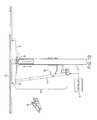
FIGs. 1A-1B are respective perspective and side views of a photovoltaic array equipped with an electromechanical solar tracker, according to an exemplary embodiment. -
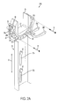
FIGs. 2A and2B are perspective side of a solar tracker bearing, according to an exemplary embodiment, showing open and closed states. -
FIGs. 3A and3B are perspective views of a solar tracker bearing, according to another exemplary embodiment, showing open and closed states. -
FIG. 4 is a perspective view of an inner bearing race usable in theFIGs. 2A-2B and3A-3B embodiments. -
FIG. 4A is a perspective view of an inner bearing race according to a second exemplary embodiment. -
FIG. 4B is a perspective view of an inner bearing race according to a third exemplary embodiment. -
FIG. 4C is a perspective view of an inner bearing race housing according to a disclosed embodiment. -
FIG. 4D is a bottom perspective view of a tube support according to a disclosed embodiment. -
FIG. 4E is a bottom perspective view of a tube support according to a second disclosed embodiment. -
FIG. 5 is a perspective view of an outer bearing race usable in theFIGs. 2A-2B and3A-3B embodiments. -
FIG. 6 is a side view of another exemplary embodiment of a solar tracker bearing. - In the following detailed description, reference is made to the accompanying drawings which form a part hereof, and which illustrate specific embodiments of the invention. These embodiments are described in sufficient detail to enable those of ordinary skill in the art to make and use them. It is also understood that structural, logical, or procedural changes may be made to the specific embodiments disclosed herein without departing from the spirit or scope of the invention.
-
Figures 1A and1B illustrate asolar tracking system 100, which can be used to support a plurality ofphotovoltaic modules 50. Thesystem 100 comprises aframe 10 of transversely arrangedelongated members 11 mounted atop a pair of longitudinally arrangedelongated members 14. One or morephotovoltaic panels 50 can be mounted on the transversely arrangedelongated members 11 and secured thereto by clips. The longitudinally arrangedelongated members 14 are mounted on respective ends of one ormore saddle brackets 15, which are secured atop atorque tube beam 13 at the center of the rotatingframe 10.Torque tube beam 13, which can be square, round, or other shape, is seated in one or moresolar tracker bearings 20A that are mounted atoprespective support posts 12. Attached to one of thesupport posts 12 is anelectromechanical actuator 40 that is controlled by acontroller 18 and used to adjust the inclination angle offrame 10. As can be seen in more detail inFigure 1B ,electromechanical actuator 40 comprises adrive screw 41 secured to supportpost 12 through anattachment bracket 42 and to frame 10 by alever arm 43, which is secured totorque tube beam 13. Extension or retraction of thedrive screw 41 causeslever arm 43 to rotatetorque tube beam 13 in thebearings 20A, changing the inclination angle offrame 10. Thedrive screw 41 may be moveable by anelectric motor 19, hydraulics, or other motorized power source under control ofcontroller 18. -
Figures 2A and2B show a first embodiment of a solar tracker bearing, 20A.Bearing 20A comprises abearing securing element 21 which mounts bearing 20A to a support post 12 (as better shown inFIG. 1B ). Bearing securingelement 21 comprises a pair of Z-axis (height)adjustable mounting slots bearing securing element 21 to supportpost 12. In this manner, the Z-axis position (height) of theentire bearing 20A can be easily adjusted along the direction of arrow A. - Atop bearing securing
element 21 is a rigid U-shapedbearing support element 23 to which a pair of stationary U-shaped outer bearingraces more mounting holes 32a-d extending throughouter bearing races support element 23, by bolts, screws or other attachment means 37. The mounting holes may be arranged so that the mounting of eachouter bearing race separate mounting holes 32a-d and can be mounted to bearing securingelement 21 individually (and thus, uninstalled individually). The arrangement of the outer bearingraces bearing surface 38 is raised above a topmost portion ofbearing support element 23, forming agroove 36 between the outer bearingraces - Bearing securing
element 21 and bearingsupport element 23 are preferably galvanized steel, but can be any suitable material with similar properties.Outer bearing races bearing 20A. - In this first embodiment, bearing securing
element 21 and bearingsupport element 23 are integrated as a single structural element, in this case a single piece of galvanized steel. Bearing securingelement 21 andbearing support element 23 may be separate structures, or, in another embodiment, completely integrated withsupport post 12. It is also understood that U-shapedouter bearing races FIG. 6 ), that is, a single outer bearing race may be used. Such a single outer bearing race could be formed to fit overbearing support element 23 with, or without agroove 36. - A rotatable inner bearing
race 25 is positionedatop bearing surface 38 over the outer bearingraces race 25 is held in place laterally bytongue 26, which is positioned ingroove 36, thus preventing inner bearingrace 25 from being displaced laterally from thebearing 20A. Inner bearingrace 25 is also prevented from being lifted out of bearing 20A because the arcs of outer bearingraces race 25 between them without additional parts. - The inner bearing
race 25 provides anopen beam slot 27 in which atorque tube beam 13 can be seated.Inner bearing race 25 is shown by itself inFIG. 4 for clarity, while anouter bearing race 24b is shown by itself inFIG. 5 .Beam slot 27, shown having a square shape, can be configured in any shape, which matches a cross-section oftorque tube beam 13. Theopen beam slot 27 provides for lateral movement tolerances by holding thetorque tube beam 13 for rotation without being connected to it, and permitstorque tube beam 13 to be simply lowered into theinner bearing race 25 of bearing 20A, e.g., by a forklift or other lifting and lowering method.Inner bearing race 25 is preferably stainless steel, but can be any other material that is suitable for holding thetorque tube beam 13. - The
torque tube beam 13 is held in place oninner bearing race 25 by gravity. In addition, optional capture straps 28a and 28b can also be used to open and close the top of thebearing 20A after thetorque tube beam 13 is installed to help holdtorque tube beam 13 in place on thebearing 20A. Twocapture straps single capture strap 28a may be employed. The capture straps 28a and 28b are preferably galvanized steel, but can be any suitable material with similar properties. It can be appreciated that the end ofcapture straps holes outer bearing races outer bearing races bearing support element 23. - In other embodiments, the
inner bearing race 25a,b may be formed from multiple components as shown inFIGs. 4A and4B . To reduce cost compared to theinner bearing race 25 and simplify assembly, theinner bearing race 25a is formed of an innerbearing race housing 44 and tube supports 45a,b as shown inFIG. 4A . In one embodiment, the innerbearing race housing 44 may be stainless steel, aluminum, a high-strength polymer, or a similar material. The tube supports 45a,b (shown in detail inFIGs. 4D and 4E ) are fastened to the inner bearing race housing 44 (shown in detail inFIG. 4C ). In one embodiment, the tube supports 45a,b may be formed from a molded polymer with moldedclips 46 that fasten to attachment points 47 (shown inFIG. 4C ) on the innerbearing race housing 44. In one embodiment, the tube supports 45a,b are formed from a glass-reinforced polymer. In another embodiment, the tube supports 45a,b are formed with anarcuate surface 48. Thearcuate surface 48 enables thetorque tube assembly 13 to be placed in theinner bearing race 25a,b with a rotational tolerance such that thetorque tube assembly 13 may be rotated even if the sides of thetorque tube assembly 13 are not completely square to thearcuate surface 48 of the tube supports 45a,b. - In one embodiment, the
tube support 45a is provided withtabs 49 as shown inFIGs. 4A and4E . Thetabs 49 aid in preventing the lever arm 43 (shown inFIG. 1B ) from sliding relative to theinner bearing race 25a in the event of a seismic event such as an earthquake. Theinner bearing race 25a provided with thetabs 49 could be provided in the lever arm 43 (shown inFIG. 1B ). Thetabs 49 would then extend from one inner surface of thelever arm 43 to the opposing inner surface, acting as spacers. In addition, thetabs 49 also serve to provide additional support to thetorque tube beam 13 such that adjacent support posts 12 can be spaced a greater distance apart. In another embodiment, shown inFIG. 4B , only tube supports 45b may be used in theinner bearing race 25b instead oftube support 45a. -
Figures 3A and3B show a second embodiment of a solar tracker bearing, 20B, which separates thebearing securing element 21 from U-shapedbearing support element 23. In bearing 20B, bearingsupport element 23 is mountable to bearing securingelement 21 at a pair of transverselyadjustable mounting slots upper flange 29 of bearing securingelement 21. Bolts, screws, or other attachment means 34 may pass through theslots support element 23 to securebearing support element 23 to bearing securingelement 21. This embodiment permits the transverse position of bearing 20B to be adjusted relative to supportpost 12 in the direction of arrow B. -
FIG. 6 shows a third embodiment of a solar tracker bearing, 20C, which omitsinner bearing race 25 and mounts around torque tube 13C directly onsurface 38 in a singleouter bearing race 24C. - The bearing designs 20A, 20B and 20C shown in
FIGs. 2A-2B ,3A-3B and6 are all suitable for mass production and easy installation, as they have relatively few parts and allow a simple design for rotation of torque tube beams 13. This lowers the total cost of asolar tracker system 100 usingbearings - While several embodiments have been described in detail, it should be readily understood that the invention is not limited to the disclosed embodiments. Rather the embodiments can be modified to incorporate any number of variations, alterations, substitutions or equivalent arrangements not heretofore described. Although certain features have been described with some embodiments of the carrier, such features can be employed in other embodiments of the carrier. While several embodiments have been described in detail, it should be readily understood that the invention is not limited to the disclosed embodiments. Rather the embodiments can be modified to incorporate any number of variations, alterations, substitutions or equivalent arrangements not heretofore described. Although certain features have been described with some embodiments of the carrier, such features can be employed in other embodiments of the carrier as well. Accordingly, the invention is not limited by the foregoing description, but is only limited by the scope of the appended claims.
Claims (15)
- A solar tracking system comprising:at least one solar tracking bearing atop a support post, the solar tracking bearing comprising a pair of stationary outer bearing races attached on either side of a bearing support element, and a rotatable inner bearing race held by the pair of outer bearing races, the rotatable inner bearing race having an beam slot for seating a torque tube beam therein;a torque tube beam seated in the beam slot;a frame on which one or more photovoltaic modules can be mounted, the frame being secured to the torque tube beam; andan electromechanical actuator operable to control the inclination angle of the frame by causing the torque tube beam to rotate in the at least one solar tracking bearing.
- The solar tracking system of claim 1, wherein the frame is secured to the torque tube beam by one or more brackets.
- The solar tracking system of claim 1, wherein the tracker comprises an actuator attached to the torque tube beam by a lever arm adapted to rotate the torque tube beam by extension or retraction of the actuator.
- The solar tracking system of claim 1, further including a bearing securing element for mounting the solar tracking bearing to the support post, the bearing securing element comprising at least one mounting slot through which an attachment means may be passed to mount the bearing securing element to the support post, the slot permitting adjustment of the height of the bearing securing element relative to the support post.
- The solar tracking system of claim 1, wherein the bearing securing element is integrated with the bearing support element.
- The solar tracking system of claim 1, wherein the bearing support element is mounted to the bearing securing element.
- The solar tracking system of claim 6, wherein the bearing securing element has an upper flange with at least one mounting slot through which an attachment means may be passed to mount the bearing support element to the bearing securing element, the mounting slot permitting adjustment of the position of the bearing support element relative to the bearing securing element.
- The solar tracking system of claim 1, wherein the pair of outer bearing races are arranged to form a groove between them above a topmost part of the bearing support element, and the rotatable inner bearing race has a tongue to engage the groove; or wherein the beam slot is configured to accept a torque tube beam having a square cross-sectional shape; or wherein each of the pair of outer bearing races has at least one mounting slot through which an attachment means may be passed to mount each outer bearing race to the bearing support element.
- The solar tracking system of claim 1, wherein each of the pair of outer bearing races is individually detachable from the bearing support element.
- The solar tracking system of claim 9, wherein the pair of outer bearing races are U-shaped and have arcs that extend beyond 180 degrees to prevent the inner bearing race from being lifted out of the solar tracking bearing.
- The solar tracking system of claim 1, wherein the outer bearing races are formed of a low friction metal, polymer or bi-material metal-polymer hybrid.
- The solar tracking system of claim 11, wherein the outer bearing races are formed of polyether ether ketone (PEEK), high-modulus polyethylene (HMPE), or polyoxymethylene (POM).
- The solar tracking system of claim 1, wherein the inner bearing race is formed of stainless steel; or further including at least one capture strap attached to one of the outer bearing races adapted to open or close the top of the solar tracking bearing; or further including a pair of capture straps, one on each outer bearing race.
- A solar tracker bearing comprising:a bearing support element; a stationary outer bearing race on a bearing securing element mounted to the bearing support element and providing a bearing surface for seating a torque tube beam therein.
- The solar tracking bearing of claim 14, wherein a round torque tube beam operable to be seated directly on the bearing surface; or wherein a square torque tube beam operable to be seated in a rotatable inner bearing race held by the outer bearing race on the bearing surface; or further comprising a second stationary outer bearing race attached on the bearing securing element and providing a second bearing surface for seating a torque tube beam therein, wherein one of the outer bearing races is arranged on one side of the bearing securing element and the other of the outer bearing races is arranged on the other side of the bearing securing element.
Applications Claiming Priority (2)
| Application Number | Priority Date | Filing Date | Title |
|---|---|---|---|
| US201161522734P | 2011-08-12 | 2011-08-12 | |
| EP12758683.2A EP2742297B1 (en) | 2011-08-12 | 2012-08-10 | Solar tracking bearing and solar tracking system employing same |
Related Parent Applications (1)
| Application Number | Title | Priority Date | Filing Date |
|---|---|---|---|
| EP12758683.2A Division EP2742297B1 (en) | 2011-08-12 | 2012-08-10 | Solar tracking bearing and solar tracking system employing same |
Publications (2)
| Publication Number | Publication Date |
|---|---|
| EP3009766A1 true EP3009766A1 (en) | 2016-04-20 |
| EP3009766B1 EP3009766B1 (en) | 2017-10-04 |
Family
ID=46832590
Family Applications (2)
| Application Number | Title | Priority Date | Filing Date |
|---|---|---|---|
| EP15192024.6A Active EP3009766B1 (en) | 2011-08-12 | 2012-08-10 | Solar tracking system |
| EP12758683.2A Not-in-force EP2742297B1 (en) | 2011-08-12 | 2012-08-10 | Solar tracking bearing and solar tracking system employing same |
Family Applications After (1)
| Application Number | Title | Priority Date | Filing Date |
|---|---|---|---|
| EP12758683.2A Not-in-force EP2742297B1 (en) | 2011-08-12 | 2012-08-10 | Solar tracking bearing and solar tracking system employing same |
Country Status (3)
| Country | Link |
|---|---|
| US (2) | US8939648B2 (en) |
| EP (2) | EP3009766B1 (en) |
| WO (1) | WO2013025492A1 (en) |
Families Citing this family (70)
| Publication number | Priority date | Publication date | Assignee | Title |
|---|---|---|---|---|
| WO2013138444A1 (en) * | 2012-03-15 | 2013-09-19 | Magna International Inc. | Solar panel mounting structure |
| WO2014018560A1 (en) * | 2012-07-23 | 2014-01-30 | Magna International Inc. | Single axis solar tracker |
| US8881415B2 (en) * | 2012-09-28 | 2014-11-11 | Sunpower Corporation | Solar system alignment tool and method |
| US9466749B1 (en) * | 2012-12-10 | 2016-10-11 | Nextracker Inc. | Balanced solar tracker clamp |
| JP2016504901A (en) | 2012-12-10 | 2016-02-12 | ネクストラッカー インコーポレイテッドNEXTracker Inc. | Horizontal balance solar tracking device |
| US9766319B2 (en) | 2012-12-10 | 2017-09-19 | Nextracker Inc. | Off-set drive assembly for solar tracker |
| US10008975B2 (en) | 2012-12-10 | 2018-06-26 | Nextracker Inc. | Clamp assembly for solar tracker |
| JP2016519556A (en) * | 2013-03-15 | 2016-06-30 | サンパワー コーポレイション | Support for solar energy collection |
| US9206999B2 (en) | 2013-08-29 | 2015-12-08 | JSI Equipment Solutions LLC | Bearing for solar panel tracking system |
| US9182030B2 (en) * | 2013-09-26 | 2015-11-10 | Brent Morgan | Slew drive gearbox with spherical adjusting mount |
| US9184324B2 (en) | 2013-12-30 | 2015-11-10 | Sunpower Corporation | Sun tracking solar power system hardware and method of assembly |
| ES2450341A1 (en) * | 2014-01-29 | 2014-03-24 | Universidad Politécnica de Madrid | Horizontal longitudinal mirror support system with free rolling supports |
| USD743881S1 (en) * | 2014-09-17 | 2015-11-24 | Nextracker Inc. | Solar tracker frame |
| CN204597865U (en) | 2014-09-17 | 2015-08-26 | 耐克斯特拉克尔有限公司 | solar tracking device |
| CN105634391A (en) * | 2014-10-31 | 2016-06-01 | 比亚迪股份有限公司 | Solar cell support and solar cell array |
| WO2016073343A1 (en) * | 2014-11-03 | 2016-05-12 | First Solar, Inc. | Mounting device for a photovoltaic module |
| FR3028113B1 (en) * | 2014-11-05 | 2016-12-30 | Optimum Tracker | MONO-AX FOLLOWER SUPPORT SYSTEM FOR SOLAR SENSOR |
| AT516607B1 (en) * | 2015-06-01 | 2016-07-15 | Hilber Gmbh | Tracking device for a PV system |
| US11035591B2 (en) * | 2015-10-13 | 2021-06-15 | Corosolar Llc | Bearing assembly for solar trackers |
| US10097134B2 (en) * | 2016-02-05 | 2018-10-09 | Solarcity Corporation | Pile cap with integrated bearing housing |
| US10605489B2 (en) * | 2016-02-16 | 2020-03-31 | Gamechange Solar Corp | Apparatuses and assemblies for a solar panel installation |
| ITUB20161244A1 (en) * | 2016-03-02 | 2017-09-02 | Andrea Bauletti | SUPPORT SYSTEM FOR PHOTOVOLTAIC PANELS |
| US10256768B2 (en) | 2016-04-25 | 2019-04-09 | Cmco Solar, Llc | Photovoltaic array mounting structure |
| US10330345B1 (en) * | 2016-04-28 | 2019-06-25 | The Regents of the Univarsity of Colorado, a Body Corporate | Mechanical solar tracking and solar concentrator |
| US10931224B2 (en) | 2016-06-03 | 2021-02-23 | RBI Solar, Inc. | Single axis in-line gearbox modular tracker system |
| KR102341671B1 (en) | 2016-06-12 | 2021-12-20 | 어레이 테크놀로지 인코퍼레이티드 | How to mount clip-on mounting rails, mounting brackets and solar modules |
| US10320326B2 (en) * | 2016-09-01 | 2019-06-11 | Sunpower Corporation | Photovoltaic system bearing assembly |
| CN106766286A (en) * | 2016-11-15 | 2017-05-31 | 天津滨海光热技术研究院有限公司 | The reflector mount of adjustable support |
| CN106642761A (en) * | 2016-11-15 | 2017-05-10 | 天津滨海光热技术研究院有限公司 | Adjusting bracket of trough collector |
| CN106595096A (en) * | 2016-11-15 | 2017-04-26 | 天津滨海光热技术研究院有限公司 | Torque tube structure capable of adjusting supports |
| CN106705455A (en) * | 2016-11-15 | 2017-05-24 | 天津滨海光热技术研究院有限公司 | Trough type heat collector capable of adjusting brackets |
| GR20170100074A (en) * | 2017-02-20 | 2018-10-31 | Ευαγγελια Νικολαου Μαυριδου | Solar tracker |
| PT3589899T (en) * | 2017-03-02 | 2023-03-29 | Array Tech Inc | Spring counter-balance assemblies and solar trackers incorporating spring counter-balance assemblies |
| ES2776736T3 (en) | 2017-05-31 | 2020-07-31 | Soltec Energias Renovables Sl | Support device for a rotating axis of a solar tracker |
| US11855581B2 (en) * | 2017-07-18 | 2023-12-26 | Polar Racking Inc. | Solar panel support and drive system |
| US11283395B2 (en) | 2018-03-23 | 2022-03-22 | Nextracker Inc. | Multiple actuator system for solar tracker |
| US11230866B2 (en) * | 2018-03-25 | 2022-01-25 | Sun And Steel Solar Llc | Bearing and coupler-journal devices for panels |
| US11387771B2 (en) | 2018-06-07 | 2022-07-12 | Nextracker Llc | Helical actuator system for solar tracker |
| US10944354B2 (en) | 2018-08-08 | 2021-03-09 | OMCO Solar, LLC | Solar tracker bearing apparatus |
| US12301163B2 (en) | 2018-08-08 | 2025-05-13 | OMCO Solar, LLC | Solar tracker bearing apparatus |
| WO2020041825A1 (en) * | 2018-08-29 | 2020-03-05 | C I Corporation Pty Ltd | Single axis solar tracker assembly |
| US11271518B2 (en) | 2018-11-08 | 2022-03-08 | OMCO Solar, LLC | Mounting bracket for mounting photovoltaic modules to torque tube beam |
| US11050383B2 (en) | 2019-05-21 | 2021-06-29 | Nextracker Inc | Radial cam helix with 0 degree stow for solar tracker |
| USD905626S1 (en) | 2019-07-25 | 2020-12-22 | Nextracker Inc. | Panel rail saddle for solar module |
| US11300979B2 (en) * | 2019-09-13 | 2022-04-12 | OMCO Solar, LLC | Solar tracking system and method of operation |
| CA3165741A1 (en) * | 2020-01-24 | 2021-07-29 | Andrew Barron WORDEN | Dual motor single axis solar tracker |
| US11569780B2 (en) * | 2020-03-17 | 2023-01-31 | Sun And Steel Solar Llc | Purlin system for solar module attachment |
| WO2022056022A1 (en) | 2020-09-08 | 2022-03-17 | Nextracker Inc. | Distributed locking tracker |
| AU2021358752B2 (en) * | 2020-10-05 | 2024-08-29 | Nextpower Llc | D-shaped torque tube and bearing assemblies |
| US20220149773A1 (en) * | 2020-11-10 | 2022-05-12 | A Raymond Et Cie | Solar tracker bushing assembly |
| CN112901664B (en) * | 2021-01-19 | 2023-01-03 | 江苏中信博新能源科技股份有限公司 | Bearing and bearing seat assembly and mounting structure thereof |
| JP2024510454A (en) * | 2021-04-16 | 2024-03-07 | サン-ゴバン パフォーマンス プラスティックス コーポレイション | Bearing assembly for tracker assembly and its manufacturing and use method |
| US11817814B2 (en) * | 2021-04-28 | 2023-11-14 | James E. Straeter | Ground mounted solar power assembly |
| US11525604B1 (en) | 2021-10-21 | 2022-12-13 | Nextracker Llc | Articulation joints for terrain following solar tracker |
| CA3236259A1 (en) | 2021-10-27 | 2023-05-04 | Nextracker Llc | Fastening assembly for solar power systems and tools thereof |
| US20230141013A1 (en) * | 2021-11-09 | 2023-05-11 | Saint-Gobain Performance Plastics Pampus Gmbh | Bearing assembly for tracker assembly and methods of making and using the same |
| US12556130B2 (en) * | 2021-11-16 | 2026-02-17 | Benjamin Quintana | Single-axis photovoltaic tracking system |
| WO2023114981A2 (en) * | 2021-12-16 | 2023-06-22 | FTC Solar, Inc. | Solar tracker system including a frame assembly |
| US12218624B2 (en) | 2021-12-23 | 2025-02-04 | OMCO Solar, LLC | Solar tracker assembly with concentric drive journals |
| US11955925B2 (en) | 2022-05-17 | 2024-04-09 | OMCO Solar, LLC | Large-scale solar tracker installation control system |
| US12025349B2 (en) | 2022-05-17 | 2024-07-02 | OMCO Solar, LLC | Method of determining and responding to an overcast sky condition in a solar tracker installation |
| US12455579B2 (en) | 2022-05-17 | 2025-10-28 | OMCO Solar, LLC | Large-scale solar tracker installation control system |
| ES1293486Y (en) * | 2022-06-21 | 2022-10-24 | Trina Solar S L U | BEARING FOR FASTENING OF ROTATING SHAFTS ON SUPPORTING PILLARS |
| US11955926B2 (en) | 2022-07-26 | 2024-04-09 | Array Technologies, Inc. | Torque tube interface with bifurcated bearing housing |
| CN115199643B (en) * | 2022-08-17 | 2026-01-27 | 天合光能股份有限公司 | Torsional damping bearing, photovoltaic tracking support and photovoltaic system |
| US12393208B2 (en) | 2022-10-20 | 2025-08-19 | Omco Solor, Llc | Backtracking method for solar tracker installation |
| US12123627B2 (en) * | 2023-01-17 | 2024-10-22 | Array Tech, Inc. | Solar tracking system support devices |
| US20240429852A1 (en) * | 2023-06-20 | 2024-12-26 | Ojjo, Inc. | Truss adapters and truss bearing adapters for terrain following single-axis trackers |
| CN117134699B (en) * | 2023-09-07 | 2024-04-12 | 上海摩昆新能源科技有限公司 | A support structure and photovoltaic tracking bracket |
| EP4597833A1 (en) * | 2024-01-30 | 2025-08-06 | Jing-Xin Solar Ltd. | A solar racking system |
Citations (3)
| Publication number | Priority date | Publication date | Assignee | Title |
|---|---|---|---|---|
| CA2761089A1 (en) * | 2009-05-07 | 2010-11-11 | Osolar Limited | Synthetic resin bearing for a photovoltaic tracking system |
| KR100997883B1 (en) * | 2010-04-19 | 2010-12-02 | 주식회사 유일엔시스 | Torque tube support and solar tracker using the same |
| EP2317247A2 (en) * | 2009-10-27 | 2011-05-04 | Hierros y Aplanaciones, S.A. (HIASA) | Photovoltaic solar tracker |
Family Cites Families (16)
| Publication number | Priority date | Publication date | Assignee | Title |
|---|---|---|---|---|
| US2115579A (en) * | 1933-12-20 | 1938-04-26 | Hoe & Co R | Ink roller socket for printing machines |
| US3820860A (en) * | 1972-08-03 | 1974-06-28 | Stone Conveyor Inc | Variable bore clearance bearing |
| US4384643A (en) * | 1979-12-19 | 1983-05-24 | Cone Joseph R | Screw conveyor hanger including disassembly means |
| US4603982A (en) * | 1985-02-21 | 1986-08-05 | Auscilla Plastics, Inc. | Molded bearing |
| US4815585A (en) * | 1988-02-23 | 1989-03-28 | Custom Metalcraft, Inc. | Sanitary hanger bearing assembly |
| US6058930A (en) | 1999-04-21 | 2000-05-09 | Shingleton; Jefferson | Solar collector and tracker arrangement |
| US7531741B1 (en) | 2003-03-07 | 2009-05-12 | Sacred Power Corporation | Tracking solar shelter |
| WO2006020597A1 (en) | 2004-08-10 | 2006-02-23 | Shell Solar Industries Lp | Tracker drive system and solar energy collection system |
| CN102176473B (en) | 2007-03-23 | 2013-11-06 | 尚能有限公司 | Tilt assembly and solar collector assembly |
| KR100924300B1 (en) | 2008-04-11 | 2009-11-02 | 주식회사 솔라파크엔지니어링 | Solar position tracking device of solar collector or solar collector |
| KR100864215B1 (en) | 2008-04-23 | 2008-10-22 | 주식회사 원광엔이씨 | Photovoltaic device using multiple crankshafts |
| TWI346762B (en) | 2008-07-18 | 2011-08-11 | Univ Nat Taiwan | Rail-type solar tracking system with focusing function |
| KR101403129B1 (en) * | 2009-05-07 | 2014-06-05 | 오쏠라 유한회사 | Solar generating apparatus with solar tracker |
| TWI424136B (en) | 2009-08-24 | 2014-01-21 | Herng Jiunn Liao | Two-axes solar tracker system and apparatus for solar panel and likes |
| TWI414736B (en) | 2010-02-02 | 2013-11-11 | Herng Jiunn Liao | One-axis solar tracker system and apparatus with wind lock devices |
| US20110240006A1 (en) | 2010-04-01 | 2011-10-06 | Linke Edward J | Solar Tracking System and Method |
-
2012
- 2012-08-10 EP EP15192024.6A patent/EP3009766B1/en active Active
- 2012-08-10 WO PCT/US2012/050312 patent/WO2013025492A1/en not_active Ceased
- 2012-08-10 EP EP12758683.2A patent/EP2742297B1/en not_active Not-in-force
- 2012-08-10 US US13/572,138 patent/US8939648B2/en active Active
-
2014
- 2014-12-30 US US14/586,069 patent/US20150144751A1/en not_active Abandoned
Patent Citations (3)
| Publication number | Priority date | Publication date | Assignee | Title |
|---|---|---|---|---|
| CA2761089A1 (en) * | 2009-05-07 | 2010-11-11 | Osolar Limited | Synthetic resin bearing for a photovoltaic tracking system |
| EP2317247A2 (en) * | 2009-10-27 | 2011-05-04 | Hierros y Aplanaciones, S.A. (HIASA) | Photovoltaic solar tracker |
| KR100997883B1 (en) * | 2010-04-19 | 2010-12-02 | 주식회사 유일엔시스 | Torque tube support and solar tracker using the same |
Also Published As
| Publication number | Publication date |
|---|---|
| EP3009766B1 (en) | 2017-10-04 |
| US8939648B2 (en) | 2015-01-27 |
| WO2013025492A1 (en) | 2013-02-21 |
| EP2742297A1 (en) | 2014-06-18 |
| EP2742297B1 (en) | 2015-11-25 |
| US20130039610A1 (en) | 2013-02-14 |
| US20150144751A1 (en) | 2015-05-28 |
Similar Documents
| Publication | Publication Date | Title |
|---|---|---|
| EP2742297B1 (en) | Solar tracking bearing and solar tracking system employing same | |
| US12228662B2 (en) | Off-set drive assembly for solar tracker | |
| US20250063852A1 (en) | Horizontal balanced solar tracker | |
| JP6052913B2 (en) | Support for solar energy concentrator | |
| JP6413128B2 (en) | Solar-tracking photovoltaic solar concentrator array including a support for solar energy collection | |
| US20090014054A1 (en) | Photovoltaic solar installation | |
| US20160218663A1 (en) | Solar Photovoltaic Single Axis Tracker | |
| EP2090848A1 (en) | Biaxial solar tracker | |
| KR100941459B1 (en) | Rotating devices for dual axis solar tracking system and driving method | |
| US20200076357A1 (en) | Pivoting members for a solar array | |
| KR101264846B1 (en) | Solar tracker and solar generating apparatus having the solar tracker | |
| EP2837899A1 (en) | Tracking device for solar power generation | |
| TWI762493B (en) | Plant for producing solar energy able to be installed on farmland | |
| JP2006278738A (en) | Solar power plant | |
| US20160195303A1 (en) | Solar tracker drive mount | |
| CN112204876A (en) | Solar energy installation with pivotable and lockable module table | |
| KR101725677B1 (en) | Photovoltaic power generation system | |
| KR102142064B1 (en) | Photovoltaic panel support structure | |
| KR100941458B1 (en) | Safety devices for dual axis solar tracking system and driving method | |
| KR101482183B1 (en) | Apparatus for Condensing Light by Tracking Sun | |
| KR101616974B1 (en) | Apparatus for condensing sunlight | |
| KR20140005878U (en) | Solar tracker | |
| CN112930461A (en) | Single-shaft solar tracker assembly | |
| CN116648587A (en) | Device for producing solar energy capable of being installed on agricultural land | |
| EP4597833A1 (en) | A solar racking system |
Legal Events
| Date | Code | Title | Description |
|---|---|---|---|
| PUAI | Public reference made under article 153(3) epc to a published international application that has entered the european phase |
Free format text: ORIGINAL CODE: 0009012 |
|
| AC | Divisional application: reference to earlier application |
Ref document number: 2742297 Country of ref document: EP Kind code of ref document: P |
|
| AK | Designated contracting states |
Kind code of ref document: A1 Designated state(s): AL AT BE BG CH CY CZ DE DK EE ES FI FR GB GR HR HU IE IS IT LI LT LU LV MC MK MT NL NO PL PT RO RS SE SI SK SM TR |
|
| 17P | Request for examination filed |
Effective date: 20161020 |
|
| RBV | Designated contracting states (corrected) |
Designated state(s): AL AT BE BG CH CY CZ DE DK EE ES FI FR GB GR HR HU IE IS IT LI LT LU LV MC MK MT NL NO PL PT RO RS SE SI SK SM TR |
|
| GRAP | Despatch of communication of intention to grant a patent |
Free format text: ORIGINAL CODE: EPIDOSNIGR1 |
|
| STAA | Information on the status of an ep patent application or granted ep patent |
Free format text: STATUS: GRANT OF PATENT IS INTENDED |
|
| INTG | Intention to grant announced |
Effective date: 20170330 |
|
| GRAS | Grant fee paid |
Free format text: ORIGINAL CODE: EPIDOSNIGR3 |
|
| GRAA | (expected) grant |
Free format text: ORIGINAL CODE: 0009210 |
|
| STAA | Information on the status of an ep patent application or granted ep patent |
Free format text: STATUS: THE PATENT HAS BEEN GRANTED |
|
| AC | Divisional application: reference to earlier application |
Ref document number: 2742297 Country of ref document: EP Kind code of ref document: P |
|
| AK | Designated contracting states |
Kind code of ref document: B1 Designated state(s): AL AT BE BG CH CY CZ DE DK EE ES FI FR GB GR HR HU IE IS IT LI LT LU LV MC MK MT NL NO PL PT RO RS SE SI SK SM TR |
|
| REG | Reference to a national code |
Ref country code: GB Ref legal event code: FG4D |
|
| REG | Reference to a national code |
Ref country code: CH Ref legal event code: EP |
|
| REG | Reference to a national code |
Ref country code: AT Ref legal event code: REF Ref document number: 934435 Country of ref document: AT Kind code of ref document: T Effective date: 20171015 |
|
| REG | Reference to a national code |
Ref country code: IE Ref legal event code: FG4D |
|
| REG | Reference to a national code |
Ref country code: DE Ref legal event code: R096 Ref document number: 602012038288 Country of ref document: DE |
|
| REG | Reference to a national code |
Ref country code: DE Ref legal event code: R079 Ref document number: 602012038288 Country of ref document: DE Free format text: PREVIOUS MAIN CLASS: F24J0002540000 Ipc: F24S0030400000 |
|
| REG | Reference to a national code |
Ref country code: NL Ref legal event code: MP Effective date: 20171004 |
|
| REG | Reference to a national code |
Ref country code: LT Ref legal event code: MG4D |
|
| REG | Reference to a national code |
Ref country code: AT Ref legal event code: MK05 Ref document number: 934435 Country of ref document: AT Kind code of ref document: T Effective date: 20171004 |
|
| PG25 | Lapsed in a contracting state [announced via postgrant information from national office to epo] |
Ref country code: NL Free format text: LAPSE BECAUSE OF FAILURE TO SUBMIT A TRANSLATION OF THE DESCRIPTION OR TO PAY THE FEE WITHIN THE PRESCRIBED TIME-LIMIT Effective date: 20171004 |
|
| PG25 | Lapsed in a contracting state [announced via postgrant information from national office to epo] |
Ref country code: NO Free format text: LAPSE BECAUSE OF FAILURE TO SUBMIT A TRANSLATION OF THE DESCRIPTION OR TO PAY THE FEE WITHIN THE PRESCRIBED TIME-LIMIT Effective date: 20180104 Ref country code: FI Free format text: LAPSE BECAUSE OF FAILURE TO SUBMIT A TRANSLATION OF THE DESCRIPTION OR TO PAY THE FEE WITHIN THE PRESCRIBED TIME-LIMIT Effective date: 20171004 Ref country code: LT Free format text: LAPSE BECAUSE OF FAILURE TO SUBMIT A TRANSLATION OF THE DESCRIPTION OR TO PAY THE FEE WITHIN THE PRESCRIBED TIME-LIMIT Effective date: 20171004 Ref country code: SE Free format text: LAPSE BECAUSE OF FAILURE TO SUBMIT A TRANSLATION OF THE DESCRIPTION OR TO PAY THE FEE WITHIN THE PRESCRIBED TIME-LIMIT Effective date: 20171004 Ref country code: ES Free format text: LAPSE BECAUSE OF FAILURE TO SUBMIT A TRANSLATION OF THE DESCRIPTION OR TO PAY THE FEE WITHIN THE PRESCRIBED TIME-LIMIT Effective date: 20171004 |
|
| PG25 | Lapsed in a contracting state [announced via postgrant information from national office to epo] |
Ref country code: HR Free format text: LAPSE BECAUSE OF FAILURE TO SUBMIT A TRANSLATION OF THE DESCRIPTION OR TO PAY THE FEE WITHIN THE PRESCRIBED TIME-LIMIT Effective date: 20171004 Ref country code: IS Free format text: LAPSE BECAUSE OF FAILURE TO SUBMIT A TRANSLATION OF THE DESCRIPTION OR TO PAY THE FEE WITHIN THE PRESCRIBED TIME-LIMIT Effective date: 20180204 Ref country code: BG Free format text: LAPSE BECAUSE OF FAILURE TO SUBMIT A TRANSLATION OF THE DESCRIPTION OR TO PAY THE FEE WITHIN THE PRESCRIBED TIME-LIMIT Effective date: 20180104 Ref country code: AT Free format text: LAPSE BECAUSE OF FAILURE TO SUBMIT A TRANSLATION OF THE DESCRIPTION OR TO PAY THE FEE WITHIN THE PRESCRIBED TIME-LIMIT Effective date: 20171004 Ref country code: GR Free format text: LAPSE BECAUSE OF FAILURE TO SUBMIT A TRANSLATION OF THE DESCRIPTION OR TO PAY THE FEE WITHIN THE PRESCRIBED TIME-LIMIT Effective date: 20180105 Ref country code: LV Free format text: LAPSE BECAUSE OF FAILURE TO SUBMIT A TRANSLATION OF THE DESCRIPTION OR TO PAY THE FEE WITHIN THE PRESCRIBED TIME-LIMIT Effective date: 20171004 Ref country code: RS Free format text: LAPSE BECAUSE OF FAILURE TO SUBMIT A TRANSLATION OF THE DESCRIPTION OR TO PAY THE FEE WITHIN THE PRESCRIBED TIME-LIMIT Effective date: 20171004 |
|
| REG | Reference to a national code |
Ref country code: DE Ref legal event code: R097 Ref document number: 602012038288 Country of ref document: DE |
|
| PG25 | Lapsed in a contracting state [announced via postgrant information from national office to epo] |
Ref country code: DK Free format text: LAPSE BECAUSE OF FAILURE TO SUBMIT A TRANSLATION OF THE DESCRIPTION OR TO PAY THE FEE WITHIN THE PRESCRIBED TIME-LIMIT Effective date: 20171004 Ref country code: EE Free format text: LAPSE BECAUSE OF FAILURE TO SUBMIT A TRANSLATION OF THE DESCRIPTION OR TO PAY THE FEE WITHIN THE PRESCRIBED TIME-LIMIT Effective date: 20171004 Ref country code: CZ Free format text: LAPSE BECAUSE OF FAILURE TO SUBMIT A TRANSLATION OF THE DESCRIPTION OR TO PAY THE FEE WITHIN THE PRESCRIBED TIME-LIMIT Effective date: 20171004 Ref country code: SK Free format text: LAPSE BECAUSE OF FAILURE TO SUBMIT A TRANSLATION OF THE DESCRIPTION OR TO PAY THE FEE WITHIN THE PRESCRIBED TIME-LIMIT Effective date: 20171004 |
|
| PLBE | No opposition filed within time limit |
Free format text: ORIGINAL CODE: 0009261 |
|
| STAA | Information on the status of an ep patent application or granted ep patent |
Free format text: STATUS: NO OPPOSITION FILED WITHIN TIME LIMIT |
|
| REG | Reference to a national code |
Ref country code: FR Ref legal event code: PLFP Year of fee payment: 7 |
|
| PG25 | Lapsed in a contracting state [announced via postgrant information from national office to epo] |
Ref country code: SM Free format text: LAPSE BECAUSE OF FAILURE TO SUBMIT A TRANSLATION OF THE DESCRIPTION OR TO PAY THE FEE WITHIN THE PRESCRIBED TIME-LIMIT Effective date: 20171004 Ref country code: RO Free format text: LAPSE BECAUSE OF FAILURE TO SUBMIT A TRANSLATION OF THE DESCRIPTION OR TO PAY THE FEE WITHIN THE PRESCRIBED TIME-LIMIT Effective date: 20171004 Ref country code: IT Free format text: LAPSE BECAUSE OF FAILURE TO SUBMIT A TRANSLATION OF THE DESCRIPTION OR TO PAY THE FEE WITHIN THE PRESCRIBED TIME-LIMIT Effective date: 20171004 Ref country code: PL Free format text: LAPSE BECAUSE OF FAILURE TO SUBMIT A TRANSLATION OF THE DESCRIPTION OR TO PAY THE FEE WITHIN THE PRESCRIBED TIME-LIMIT Effective date: 20171004 |
|
| 26N | No opposition filed |
Effective date: 20180705 |
|
| PG25 | Lapsed in a contracting state [announced via postgrant information from national office to epo] |
Ref country code: SI Free format text: LAPSE BECAUSE OF FAILURE TO SUBMIT A TRANSLATION OF THE DESCRIPTION OR TO PAY THE FEE WITHIN THE PRESCRIBED TIME-LIMIT Effective date: 20171004 |
|
| PG25 | Lapsed in a contracting state [announced via postgrant information from national office to epo] |
Ref country code: MC Free format text: LAPSE BECAUSE OF FAILURE TO SUBMIT A TRANSLATION OF THE DESCRIPTION OR TO PAY THE FEE WITHIN THE PRESCRIBED TIME-LIMIT Effective date: 20171004 |
|
| REG | Reference to a national code |
Ref country code: CH Ref legal event code: PL |
|
| GBPC | Gb: european patent ceased through non-payment of renewal fee |
Effective date: 20180810 |
|
| PG25 | Lapsed in a contracting state [announced via postgrant information from national office to epo] |
Ref country code: CH Free format text: LAPSE BECAUSE OF NON-PAYMENT OF DUE FEES Effective date: 20180831 Ref country code: LI Free format text: LAPSE BECAUSE OF NON-PAYMENT OF DUE FEES Effective date: 20180831 Ref country code: LU Free format text: LAPSE BECAUSE OF NON-PAYMENT OF DUE FEES Effective date: 20180810 |
|
| REG | Reference to a national code |
Ref country code: BE Ref legal event code: MM Effective date: 20180831 |
|
| REG | Reference to a national code |
Ref country code: IE Ref legal event code: MM4A |
|
| PG25 | Lapsed in a contracting state [announced via postgrant information from national office to epo] |
Ref country code: IE Free format text: LAPSE BECAUSE OF NON-PAYMENT OF DUE FEES Effective date: 20180810 |
|
| PG25 | Lapsed in a contracting state [announced via postgrant information from national office to epo] |
Ref country code: BE Free format text: LAPSE BECAUSE OF NON-PAYMENT OF DUE FEES Effective date: 20180831 |
|
| PG25 | Lapsed in a contracting state [announced via postgrant information from national office to epo] |
Ref country code: GB Free format text: LAPSE BECAUSE OF NON-PAYMENT OF DUE FEES Effective date: 20180810 |
|
| PG25 | Lapsed in a contracting state [announced via postgrant information from national office to epo] |
Ref country code: MT Free format text: LAPSE BECAUSE OF NON-PAYMENT OF DUE FEES Effective date: 20180810 |
|
| PG25 | Lapsed in a contracting state [announced via postgrant information from national office to epo] |
Ref country code: TR Free format text: LAPSE BECAUSE OF FAILURE TO SUBMIT A TRANSLATION OF THE DESCRIPTION OR TO PAY THE FEE WITHIN THE PRESCRIBED TIME-LIMIT Effective date: 20171004 |
|
| PG25 | Lapsed in a contracting state [announced via postgrant information from national office to epo] |
Ref country code: PT Free format text: LAPSE BECAUSE OF FAILURE TO SUBMIT A TRANSLATION OF THE DESCRIPTION OR TO PAY THE FEE WITHIN THE PRESCRIBED TIME-LIMIT Effective date: 20171004 |
|
| PG25 | Lapsed in a contracting state [announced via postgrant information from national office to epo] |
Ref country code: MK Free format text: LAPSE BECAUSE OF NON-PAYMENT OF DUE FEES Effective date: 20171004 Ref country code: HU Free format text: LAPSE BECAUSE OF FAILURE TO SUBMIT A TRANSLATION OF THE DESCRIPTION OR TO PAY THE FEE WITHIN THE PRESCRIBED TIME-LIMIT; INVALID AB INITIO Effective date: 20120810 Ref country code: CY Free format text: LAPSE BECAUSE OF FAILURE TO SUBMIT A TRANSLATION OF THE DESCRIPTION OR TO PAY THE FEE WITHIN THE PRESCRIBED TIME-LIMIT Effective date: 20171004 |
|
| PG25 | Lapsed in a contracting state [announced via postgrant information from national office to epo] |
Ref country code: AL Free format text: LAPSE BECAUSE OF FAILURE TO SUBMIT A TRANSLATION OF THE DESCRIPTION OR TO PAY THE FEE WITHIN THE PRESCRIBED TIME-LIMIT Effective date: 20171004 |
|
| P01 | Opt-out of the competence of the unified patent court (upc) registered |
Effective date: 20230518 |
|
| PGFP | Annual fee paid to national office [announced via postgrant information from national office to epo] |
Ref country code: DE Payment date: 20240828 Year of fee payment: 13 |
|
| PGFP | Annual fee paid to national office [announced via postgrant information from national office to epo] |
Ref country code: FR Payment date: 20240826 Year of fee payment: 13 |
|
| REG | Reference to a national code |
Ref country code: DE Ref legal event code: R081 Ref document number: 602012038288 Country of ref document: DE Owner name: NOVASOURCE POWER HOLDINGS, INC., CHANDLER, US Free format text: FORMER OWNER: FIRST SOLAR, INC., PERRYSBURG, OHIO, US |
|
| REG | Reference to a national code |
Ref country code: DE Ref legal event code: R119 Ref document number: 602012038288 Country of ref document: DE |